

Page 1
Version 1.0
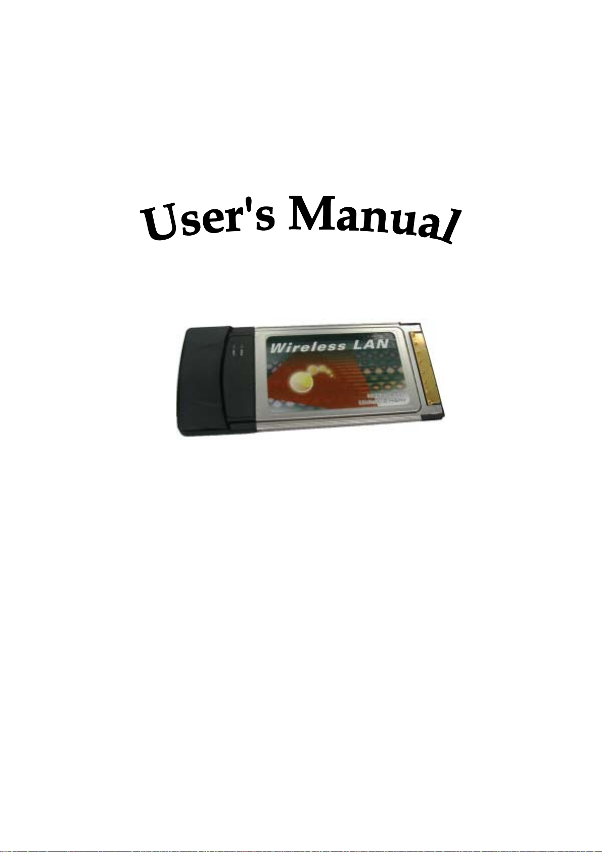
FW-C502 Wireless LAN CardBus Adapter
Copyright statement
No part of this publication may be reproduced, stored in a retrieval system, or transmitted in any
form or by any means, whether electronic, mechanical, photocopying, recording, or otherwise
without the prior writing of the publisher.
Note
Information in this manual is subject to change without notice.
Page 2
End users must follow the specific operating instructions for satisfying RF exposure compliance.
Federal Communications Commission Compliance Notice
To ensure continued compliance, use only shielded interface cables when connecting to the computer or
peripheral devices. Any changes or modifications not expressly approved by the party responsible for
compliance could void the user’s authority to operate this equipment.
This device complies with Part 15 of the FCC Rules. Operation is subject to the following two cond itions: (1)
This device may not cause harmful interference, and (2) This device must accept any interference received,
including interference that may cause undesired operation.
Federal Communication Commission (FCC) Statement:
This equipment has been tested and found to comply with the limits for a Class B digital device pursu ant to
Part 15 of the FCC Rules. These limits are designed to provide reasonable protection against harmful
interference in a residential installation. This equipment generates, uses, and can radiate radio frequency
energy and, if not installed and used in accordance with the instructions, may cause harmful interference to
radio communications. However, there is no guarantee that interference will not occur in a particular
installation. If this equipment does cause harmful interference to radio or television reception, which can be
determined by turning the equipment off and on, the user is encouraged to try to correct the interference by
one or more of the following measures:
Reorient or relocate the receiving antenna.
Increase the separation between the equipment and receiver.
Connect the equipment into an outlet on a circuit different from that to which the receiver is connected.
Consult the dealer or an experienced radio/TV technician for help.
FCC Radiation Exposure Statement
This equipment complies with FCC radiation exposure limits set forth for an uncontrolled en vironment.
This equipment should be installed and operated with a minimum distance of 2.5 cm between the
radiator and your body.
This transmitter must not be co-located or operated in conjunction with any other antenna or transmitter.
- 1 -
Page 3

Contents
1 Introduction.................................................................................................................... 4
1.1 About 802.11b Wireless LAN CardBus Adapter .................................................. 4
1.2 Features and Benefits ............................................................................................4
1.3 Product View .........................................................................................................5
2 Getting Started.............................................................................................................. 6
2.1 Package Contents ..................................................................................................6
2.2 System Requirements............................................................................................6
2.3 LED Indicators...................................................................................................... 7
2.4 Safety Precautions.................................................................................................7
2.5 Site Selection......................................................................................................... 8
3 Install & Uninstall the 802.11b Wireless LAN CardBus Adapter for Windows .......... 10
3.1 Windows XP Installation & Uninstallation......................................................... 10
3.2 Windows 2000 Installation & Uninstallation...................................................... 14
3.3 Windows 98SE/ME Installation & Uninstallation..............................................20
4 Verifying the 802.11b Wireless LAN CardBus Adapter for Windows......................... 26
4.1 Inserting the 802.11b Wireless LAN CardBus Adapter...................................... 26
4.2 Verifying Driver Installation ...............................................................................26
Verifying Driver Installation under Windows XP ................................................ 26
Verifying Driver Installation under Windows 2000 .............................................27
Verifying Driver Installation under Windows 98SE/Me ...................................... 27
4.3 Verifying Utility Installation ...............................................................................27
4.4 Removing the WLAN Card................................................................................. 28
5 Using the Configuration & Monitor Utility .................................................................30
5.1 Configure 802.11b Wireless LAN CardBus Adapter Under Windows XP.........30
5.2 Usage of the Configuration & Monitor Utility.................................................... 32
Status.................................................................................................................... 33
Statistics................................................................................................................ 35
Site Survey ........................................................................................................... 36
Encryption............................................................................................................ 37
Advanced.............................................................................................................. 38
- 2 -
Page 4

About....................................................................................................................39
5.3 Usage of the Change Region Tool....................................................................... 40
6 Troubleshooting............................................................................................................ 41
Appendix A WLAN CardBus Adapter Specification........................................................44
- 3 -
Page 5

1 Introduction
This chapter introduces the features and functions of the product.
1.1 About 802.11b Wireless LAN CardBus Adapter
Congratulations on purchasing this Wireless Local Area Network (WLAN) Card.
Your 802.11b Wireless LAN CardBus Adapter ’s 11 Mbps data rate provides an
equivalent Ethernet speed to access corporate networks or the Internet in a
wireless environment. When installed, the WLAN Card is able to communicate
with any 802.11b-compliant product, allowing you to work anywhere in the
coverage area, enjoying its convenience and mobility.
1.2 Features and Benefits
IEEE 802.11b and Wi-Fi-compliant 11 Mbps WLAN access solution
Direct Sequence Spread Spectrum (DSSS) standard
Built-in antenna
Wired Equivalent Privacy (WEP) 128-bit data encryption
Frequency range at 2.4 GHz ISM band
Automatic data rate selection at 11 Mbps, 5.5 Mbps, 2 Mbps, and 1 Mbps
(automatic data rate fallback under noisy environment)
- 4 -
Page 6
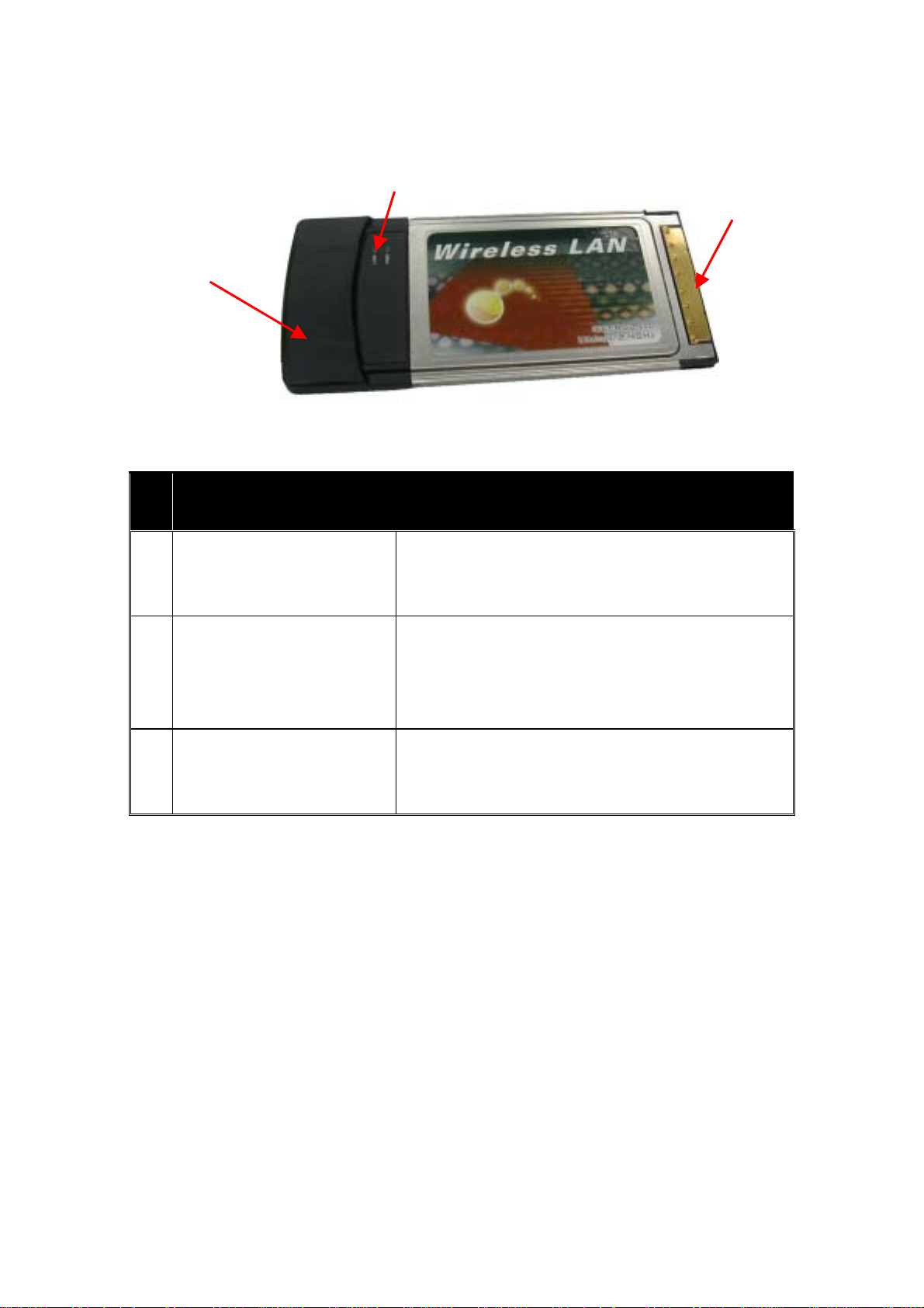
1.3 Product View
802.11b Wireless LAN CardBus Adapter
Component Description
802.11b Wireless LAN CardBus
Adapter Connector
Wireless Connection Indicator
(LINK)
Integrated Antenna
Connects to your computing device. The interface is
PCMCIA slot.
Glows green when the WLAN Card has successfully linked
with an Access Point (Infrastructure mode) or with another
wireless station (Ad-Hoc mode).
Allows the WLAN Card to receive and transmit wireless
data.
- 5 -
Page 7
2 Getting Started
This chapter provides the information that you need before you start to install the
802.11b Wireless LAN CardBus Adapter.
2.1 Package Contents
If any of the listed items are damaged or missing, please notify your local dealer.
FW - C502 802.11b Wireless LAN CardBus Adapter
CD-ROM (containing Drivers and Manual)
Quick Installation Guide
2.2 System Requirements
Before installing the FW-C502 802.11b Wireless LAN CardBus Adapter, the
following equipments may be required in order to install the adapter properly:
Operating system: Windows 98SE, Windows Me, Windows 2000, or
Windows XP
Desktop or laptop computer with CD-ROM drive
ISA to CardBus or PCI to CardBus controller in case of desktop
PCMCIA type II or type III card slot in case of laptop
NOTE: CardBus controller must support 3.3V PC card.
Caution!
Do not insert your WLAN Card into the PCMCIA slot at this stage until you have
finished installation.
- 6 -
Page 8

2.3 LED Indicators
The 802.11b Wireless LAN CardBus Adapter has two LED indicators, which will
glow or blink to reflect operation status. The described as below:
Power LED (PWR) – The LED lights up when the 802.11b Wireless
LAN CardBus Adapter is receiving power.
Link Activity LED (LINK)– The LED blinks fast when the 802.11b
Wireless LAN CardBus Adapter is linking with the network and LED
blinks slowly when the 802.11b Wireless LAN CardBus Adapter is
receiving or transmitting data.
2.4 Safety Precautions
Be sure to read and follow all warning notices and instructions.
In order to extend the life of the device it is advised to store it in a protective
casing whenever carrying the computing device on travel and not operating
the device.
Never use abrasive materials or rinse the device with liquids.
At all times, it will be the responsibility of the end-user to ensure that an
outdoor antenna installation complies with local radio regulations.
Do not service the product by yourself. Refer all servicing to qualified service
personnel.
In order to limit Radio Frequency (RF) exposure, the following rules should
be applied:
1. Install the antenna in a location where a distance of 20 cm from the
antenna may be maintained.
2. While installing the antenna in the location, please do not turn on power
of the device.
3. While the device is working (transmitting or receiving), please do not
touch or move the antenna.
4. Do not operate a portable transmitter near unshielded blasting caps or in
an explosive environment unless it is a type especially qualified for such
use.
- 7 -
Page 9

For Laptop (laptop) computer users, in order to comply with the FCC RF
exposure limits, it is recommended when using a laptop with a wireless device
that the device’s integrated antenna should not be positioned closer than 5 cm
(2 inches) from your body or nearby persons for extended periods of time
while it is transmitting (or operating). If the antenna is positioned less than 5
cm (2 inches) from the user, it is recommended that the user limit exposure
time.
2.5 Site Selection
Typical outdoor operating range:
11 Mbps
(High speed)
5.5 Mbps
(Medium
speed)
2 Mbps
(Standard
speed)
1 Mbps
(Low speed)
Range 250 M 280 M 350 M 420 M
The range of the wireless signal is related to the Transmit Rate of the wireless
communication (Tx Rate on the Status utility of the Configuration & Monitor
Application utility). Communications at lower transmit range may travel larger
distances.
If you intend to use the WLAN Card as part of an outdoor antenna installation, the
range of the outdoor antenna installation will be related to clearance of the radio
signal path.
The typical conditions when used indoors in “office environments” can be
described as follows:
In Open Office environments, there should be no physical obstructions
between two antennas. This is an ideal indoor antenna installation.
In Semi-open Office environments, workspace is divided by shoulder-height,
hollow wall elements; antenna are at desktop level. This describes the typical
indoor antenna installation.
In Closed Office environments, workspace is separated by floor-to-floor
ceiling and walls are made of out brick or concrete. This type of indoor
antenna installation is not applicable to your WLAN card.
- 8 -
Page 10

NOTE 1: The range values listed above are typical distances measured. These values
may provide a rule of thumb and may vary according to the actual radio conditions at the
location where the WLAN card will be installed.
NOTE 2: The range of your wireless devices can be affected when the antennas are
placed near metal surfaces and solid high-density materials.
NOTE 3: Obstacles in the signal path of the radio that may either absorb or reflect the
radio signal also affect the range.
- 9 -
Page 11
3 Install & Uninstall the 802.11b Wireless
LAN CardBus Adapter for Windows
This chapter provides the instructions that guide you through the driver installation
or uninstallation of your 802.11b Wireless LAN CardBus Adapter for the
Windows XP\2000\98SE\ME operating systems. The installation processes for
Windows XP, please refer to 3.1 Windows XP Installation; for Windows 2000
refer to 3.2 Windows 2000 Installation; for Windows98SE/ME, please see 3.3
Windows 98SE/ME Installation.
3.1 Windows XP Installation & Uninstallation
Follow the instructions below to install the driver and utility on a computer
running Windows XP.
1. Turn on the computer and insert the driver CD into the appropriate drive.
Do not insert your WLAN Card into the PCMCIA Slot until you have
finished the software installation.
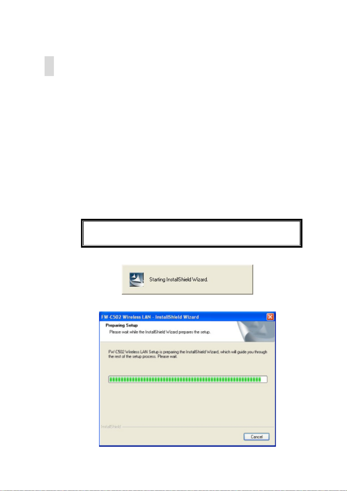
2. The install will automatically appear.
3. The installation will start.
- 10 -
Page 12
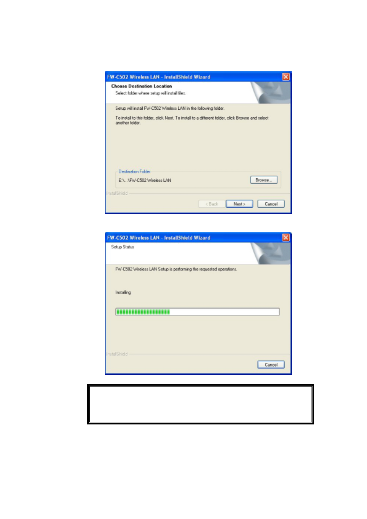
S
4. Click “Next” button to continue installation.
5. Finish the installation.
If the AutoRun function on your computer does not automatically
start, then select your CD-ROM driver and double-click the file,
ETUP.EXE under the Windows directory.
- 11 -
Page 13
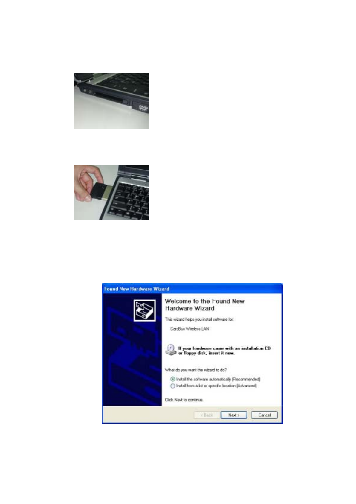
6. Find the location of the PCMCIA slot on your laptop.
7. Insert the Wireless CardBus Adapter into the PCMCIA slot on your laptop.
(as shown)
8. After inserting the WLAN Card into your computer, Windows will
automatically detect that new hardware has been installed. Depending on
which operating system you are using, the steps and screens may differ
slightly. Click “Next” to continue installing.
- 12 -
Page 14
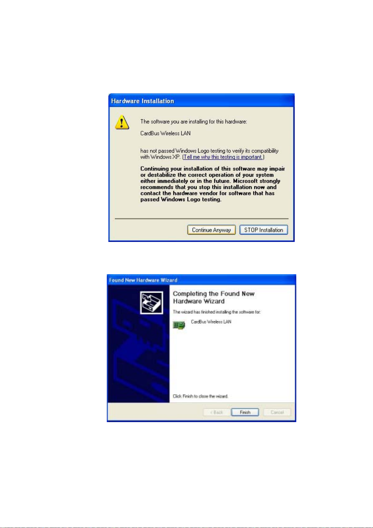
9. For Windows XP, the following screen may appear. Click “Continue
Anyway”.
10. Click “Finish” to finalize the installation.
Follow the instructions below to uninstall the driver and utility on a computer
running Windows XP.
- 13 -
Page 15
y
1. Exit the Configuration & Monitor Utility icon. If it is currently active, this icon is
loaded on the system tray of Windows task bar, right click to exit then eject the WLAN
Adapter.
2.
Select the “Uninstall Cardbus Wireless LAN Adapter” option by clicking on Start, then
Programs → Wireless LAN Adapter and the uninstall wizard will guide you through the
uninstall process.
3.
The other way to uninstall is to access the Windows Control Panel and select the
“Add/Remove Programs” option and follow the instructions to uninstall.
If during the uninstall process you receive an error message, insert the driver CD
and try to uninstall again.
3.2 Windows 2000 Installation & Uninstallation
Follow the instructions below to install the driver and utility on a computer
running Windows 2000.
1. Turn on the computer and insert the driver CD into the appropriate driver.
Do not insert your WLAN Card into the PCMCIA slot at this stage until
ou have finished installation.
2. The install screen will automatically appear.
3. The installation will start.
- 14 -
Page 16
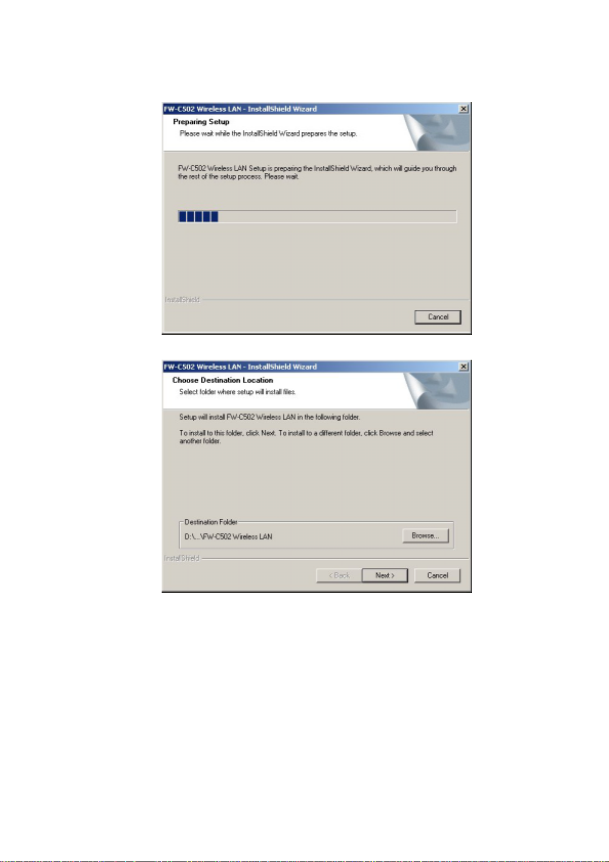
4. Click “Next” button to continue installation.
- 15 -
Page 17
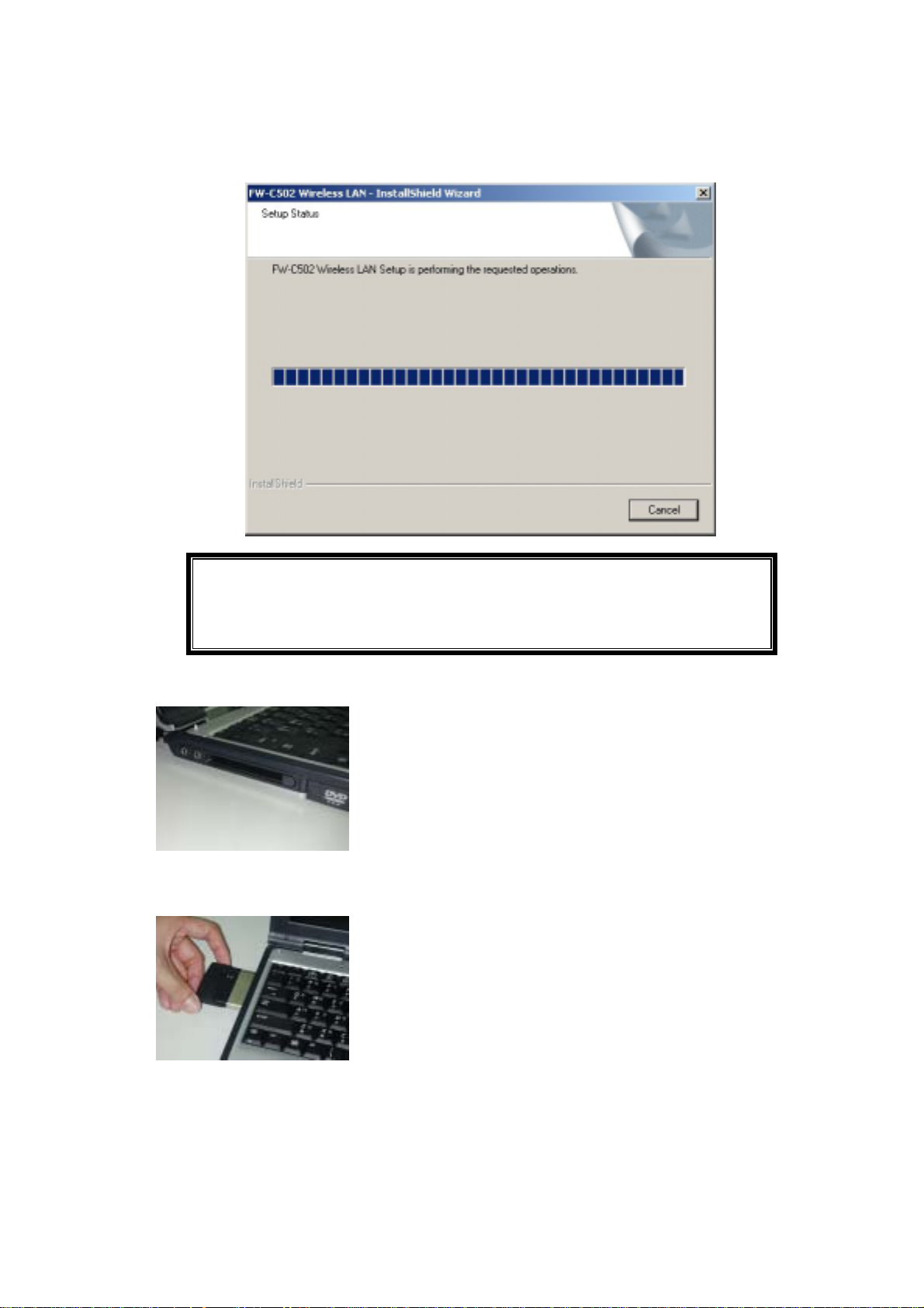
5. Finish the installation.
If the AutoRun function on your computer does not automatically
start, then select your CD-ROM driver and double-click the file,
SETUP.EXE under the Windows directory.
6. Find the location of the PCMCIA slot on your laptop.
7. Insert the Wireless CardBus Adapter into the PCMCIA slot on your laptop.
8. After inserting the WLAN Card into your computer, Windows will automatically
detect that new hardware had been installed. Depending on which operating
system you are using, the steps and screens may differ slightly. Click “Next” to
continue installing.
- 16 -
Page 18
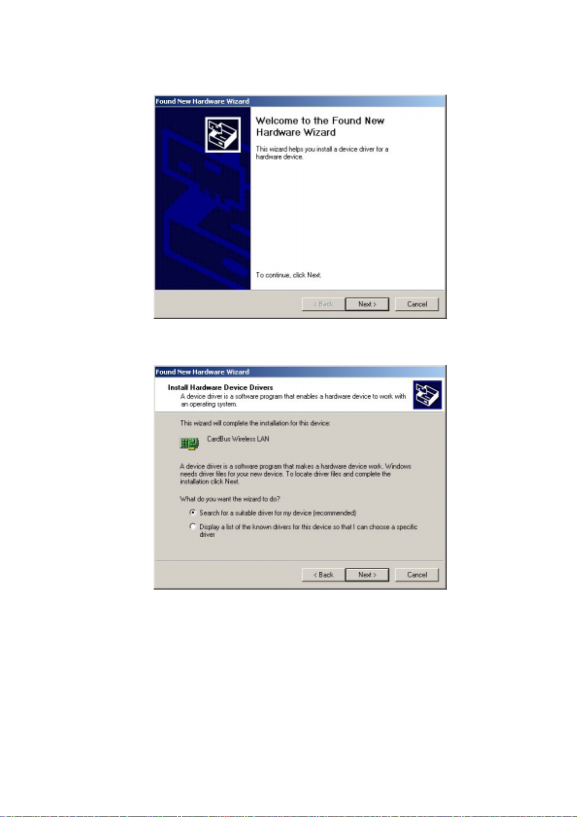
9. Select “Search for a suitable driver for my device (recommended)” and click
Next to proceed.
10. Un-check all check box and click on Next to install the driver.
- 17 -
Page 19
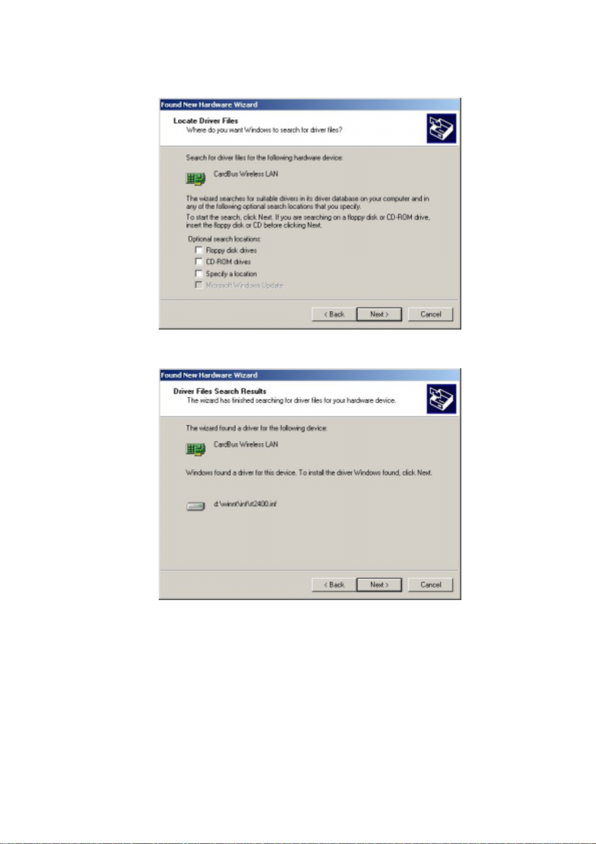
11. The Windows will find “CardBus Wireless LAN”. Click Next to continue.
12. For Windows 2000, a Digital Signature Not Found message will appear. Click
“Yes” to continue setup.
- 18 -
Page 20
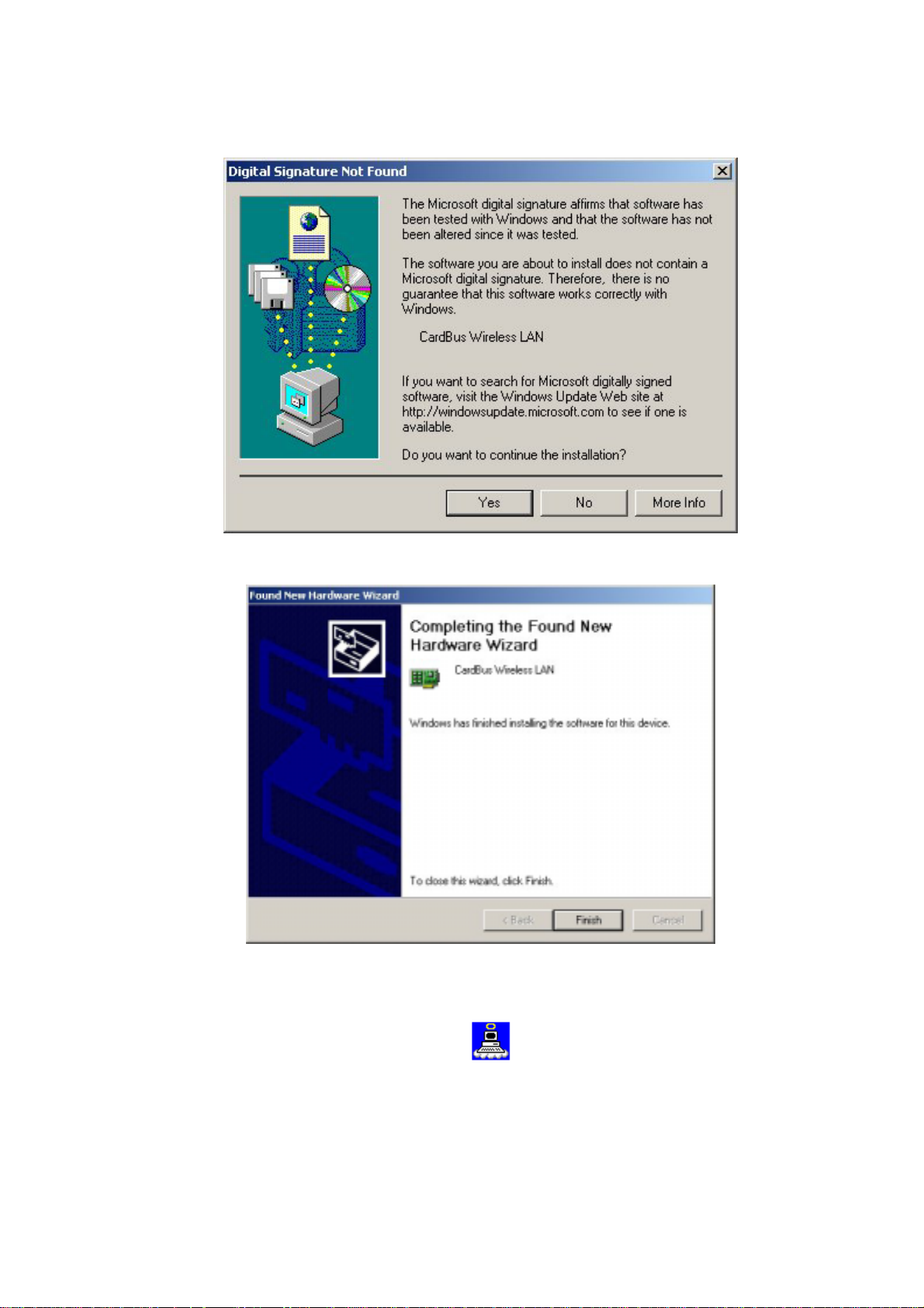
13. Complete the installation.
Follow the instructions below to uninstall the driver and utility on a computer running
Windows 2000.
1. Exit the Configuration & Monitor Utility icon. If it is currently active, this icon is
loaded on the system tray of Windows task bar, right click to exit then eject the WLAN
Adapter.
- 19 -
Page 21
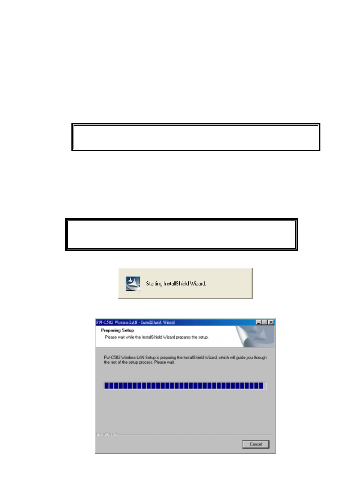
2. Select the “Uninstall Cardbus Wireless LAN Adapter” option by clicking on Start, then
Programs → Wireless LAN Adapter and the uninstall wizard will guide you through the
uninstall process.
3. The other way to uninstall is to access the Windows Control Panel and select the
“Add/Remove Programs” option and follow the instructions to uninstall.
If during the uninstall process you receive an error message, insert the driver CD
and try to uninstall again.
3.3 Windows 98SE/ME Installation & Uninstallation
Follow the instructions below to install the driver and utility on a computer
running Windows 98SE/ME.
1. Turn on the computer and insert the driver CD into the appropriate drive.
Do not insert your WLAN Card into the PCMCIA slot at this stage until you
have finished installation.
2. The install screen will automatically appear.
3. The screen will start.
- 20 -
Page 22
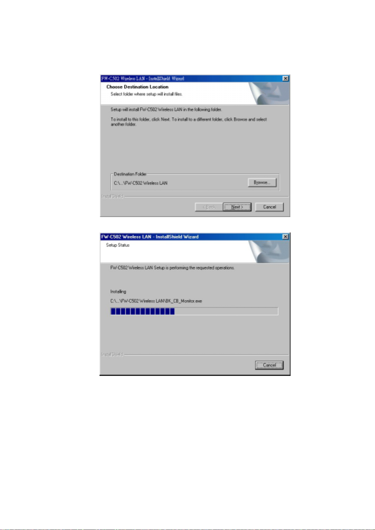
4. Click “Next” to continue installation.
5. Finish the installation.
6. Restart the computer.
- 21 -
Page 23
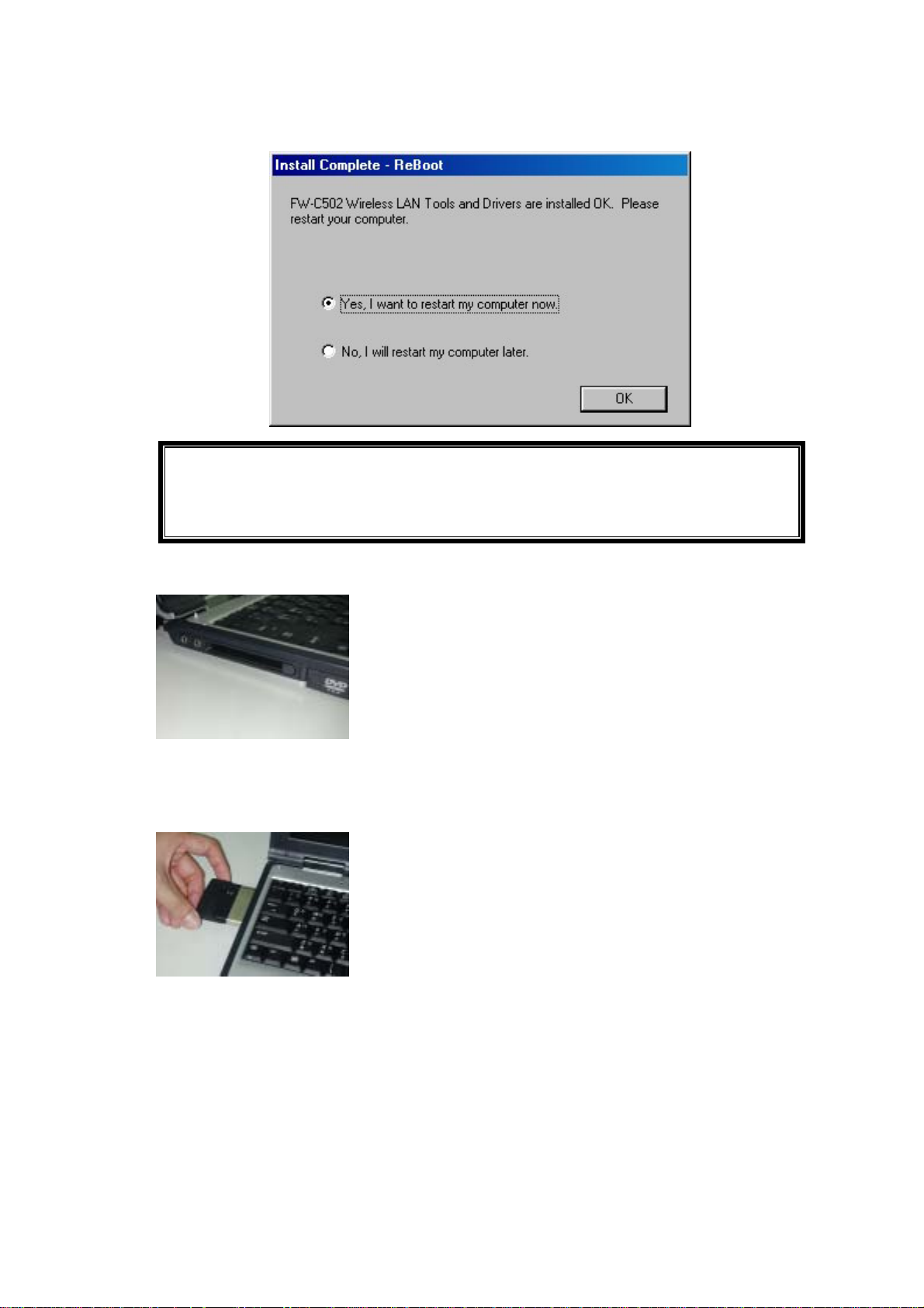
If the AutoRun function on your computer does not automatically start, then
select your CD-ROM drive and double-click the file, SETUP.EXE under the
Windows directory.
7. Find the location of the PCMCIA slot on your laptop.
8. Insert the Wireless CardBus Adapter into the PCMCIA slot on your laptop (as
shown)
9. After inserting the WLAN Card into your computer, Windows will automatically
detect that new hardware has been installed. Depending on which operating system
you are using, the steps and screens may differ slightly. Click “Next” to continue
installing.
- 22 -
Page 24
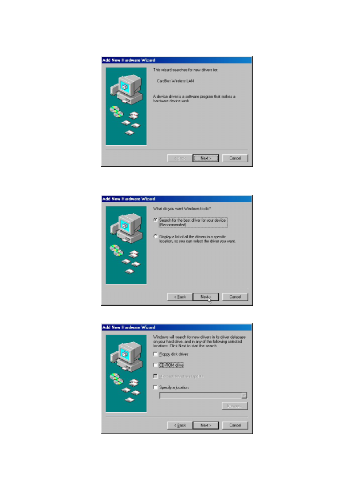
10. Select “Search for the best driver for your device (Recommended)” and click
“Next” to proceed.
11. Un-check all check box and click on “Next” to install the driver.
- 23 -
Page 25
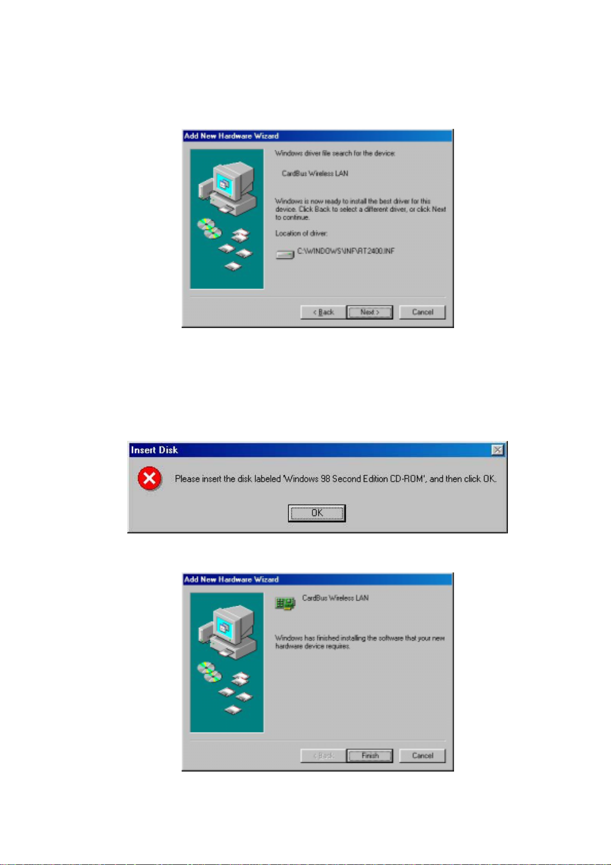
12. The Windows will find “CardBus Wireless LAN”. Click “Next” to continue.
13. Follow the instructions to install driver. For Windows 98SE, [Please insert the disk
labeled “Windows 98 Second Edition CD-ROM CD-ROM”, and then click OK]
window appears, insert and enter the path corresponding to the appropriate drives
and click OK. Usually these files could be found at C:\\ Windows or
C:\\Windows\system.
14. Click “Finish” to complete the software installation.
- 24 -
Page 26
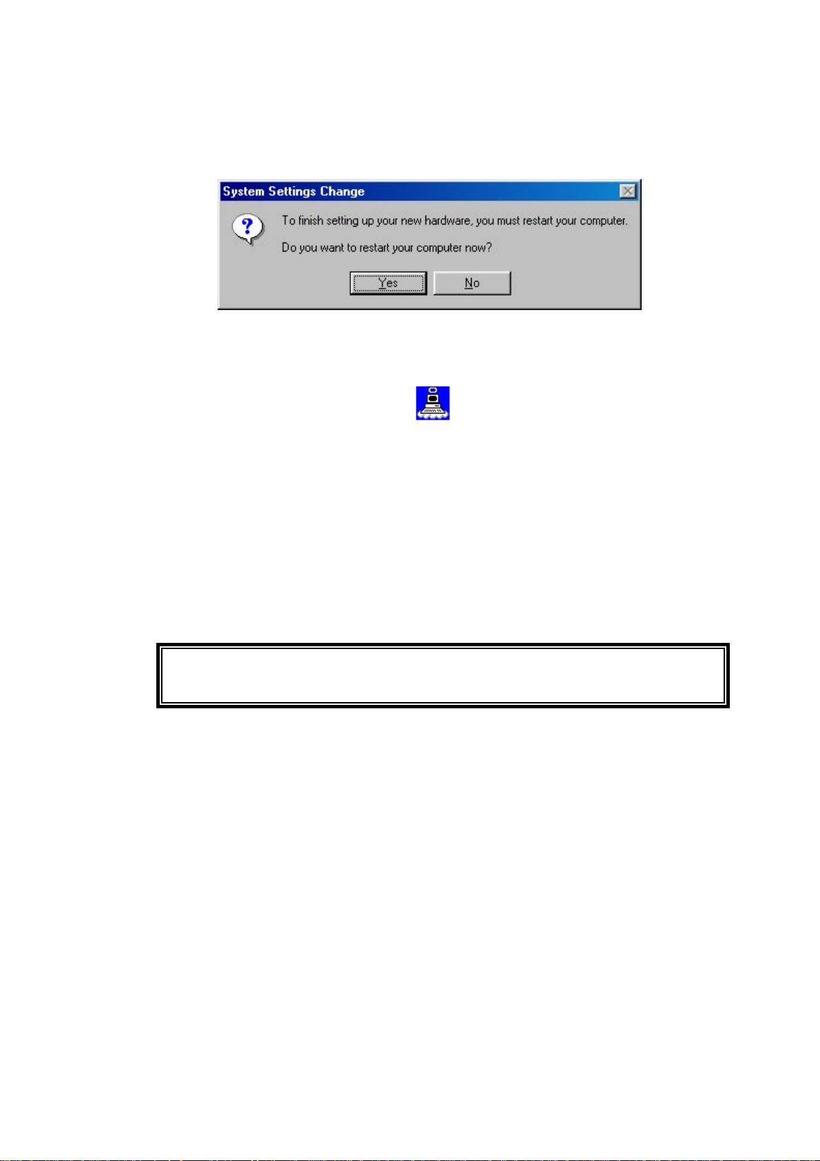
15. Restart the computer.
Follow the instructions below to uninstall the driver and utility on a computer
running Windows 98SE/ME.
1. Exit the Configuration & Monitor Utility icon. If it is currently active, this icon is
loaded on the system tray of Windows task bar, right click to exit then eject the WLAN
Adapter.
2. Select the “Uninstall Cardbus Wireless LAN Adapter” option by clicking on Start, then
Programs → Wireless LAN Adapter and the uninstall wizard will guide you through the
uninstall process.
3. The other way to uninstall is to access the Windows Control Panel and select the
“Add/Remove Programs” option and follow the instructions to uninstall.
If during the uninstall process you receive an error message, insert the driver CD
and try to uninstall again.
- 25 -
Page 27
4 Verifying the 802.11b Wireless LAN
CardBus Adapter for Windows
This section provides the instructions that guide you to verify proper operation of
the driver and utility of your 802.11b Wireless LAN CardBus Adapter for the
Windows XP\2000\98SE\ME operating systems.
4.1 Inserting the 802.11b Wireless LAN CardBus Adapter
To insert the 802.11b W ireless LAN CardBus Adapter, please follow the
guidelines below:
1. Find an available PCMCIA type II or type III card slot in your computing
device.
2. With the WLAN Card adapter’s connector facing the PCMCIA slot, slide the
card completely into the slot (refer to your system manual for the correct
orientation).
3. Your WLAN card should start searching for wireless signals from an AP
(Infrastructure mode) or another wireless station (Ad-Hoc mode).
NOTE: Make sure that the 802.11b Wireless LAN CardBus Adapter’s driver as
well as the Configuration & Monitor Application utility has been properly
installed (see previous section).
4.2 Verifying Driver Installation
To verify that you have properly installed the driver of the 802.11b Wireless LAN
CardBus Adapter, check the 802.11b Wireless LAN CardBus Adapter’s LED or
verify driver installation under Windows XP/2000/98SE/ME operating systems.
Verifying Driver Installation under Windows XP
1. Start → Select “Settings” → click “Control Panel” and double-click the
“System” icon.
2. Click on “My Computer” → select “Properties” from the Windows XP
desktop.
3. Click on the “Hardware” folder tab and click the “Device Manager” button.
4. Click the “Network adapters”.
- 26 -
Page 28

5. There should be no yellow exclamation or red cross-sign in the front of the
802.11b Wireless LAN CardBus Adapter.
6. Double-click the 802.11b Wireless LAN CardBus Adapter and the Device Status
windows should indicate that the 802.11b Wireless LAN CardBus Adapter is
working properly.
Verifying Driver Installation under Windows 2000
1. Start → Select “Settings” → click “Control Panel” and double-click the
“System” icon.
2. Click on “My Computer” → select “Properties” from the Windows 2000
desktop.
3. Click on the “Hardware” folder tab and click the “Device Manager” button.
4. Click the “Network adapters”.
5. There should be no yellow exclamation or red cross-sign in the front of the
802.11b Wireless LAN CardBus Adapter.
6. Double-click the 802.11b Wireless LAN CardBus Adapter and the Device Status
windows should indicate that the 802.11b Wireless LAN CardBus Adapter is
working properly.
Verifying Driver Installation under Windows 98SE/Me
1. Start → Select “Settings” → click “Control Panel” and double-click the
“System” icon.
2. Click on “My Computer” → select “Properties” from the Windows 98/ME
desktop.
3. Click on the “Hardware” folder tab and click the “Device Manager” button.
4. Click the “Network adapters”.
5. There should be no yellow exclamation or red cross-sign in the front of the
802.11b Wireless LAN CardBus Adapter.
6. Double-click the 802.11b Wireless LAN CardBus Adapter and the Device Status
windows should indicate that the 802.11b Wireless LAN CardBus Adapter is
working properly.
4.3 Verifying Utility Installation
To verify the utility of the 802.11b Wireless LAN CardBus Adapter for properly
installation, be sure the Configuration & Monitor Utility icon is loaded on
the system tray of Windows task bar every time the card is running. You can open
- 27 -
Page 29
it by double-clicking on this icon. While the station is in infrastructure mode and
not associated to an Access Point, the color of the icon is red. As soon as the
station associates itself to an Access Point (see 5-2 page 34 “Site Survey”), the
icon color automatically turns to blue. In Ad-Hoc mode the color is always blue,
except when the card is resetting and initializing where it turns to red during the
reset and initialization procedure.
4.4 Removing the WLAN Card
This section provides instructions for removing the WLAN Card. The PCMCIA slot
permits “hot swapping” of PC cards, allowing you to insert or remove the 802.11b
Wireless LAN CardBus Adapter from the slot whenever you like, even when the
power to your computer is on. However, you are advised to always disable the
802.11b Wireless LAN CardBus Adapter prior to removing it from the PCMCIA
slot. This allows the Windows operating system to:
Log off from the network server.
Disable the driver properly through the Control Panel.
Disconnect power to the PCMCIA slot.
Follow the steps below to stop using the WLAN Card:
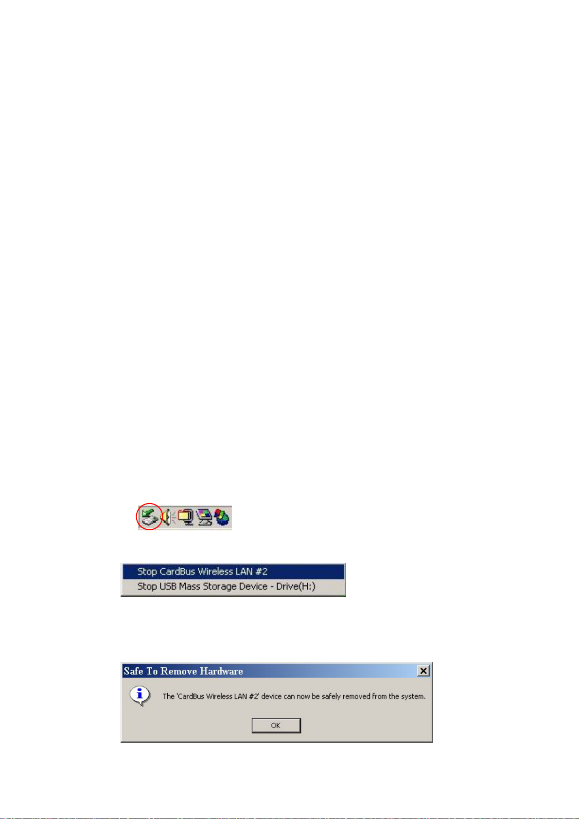
1. Click on Unplug or Eject Hardware icon on the system tray of Windows task
bar.
2.
Select the “Stop CardBus Wireless LAN #2 ”
3.
Wait a few seconds until the system pop-up a message to indicate that you
can safely remove the WLAN Card from the system. Click “OK” and then
you may eject WLAN Card.
- 28 -
Page 30

Normally, you would use the eject button to remove the WLAN Card. However,
you are advised to refer to your system’s manual on properly ejecting your 802.11b
Wireless LAN CardBus Adapter from the slot.
- 29 -
Page 31
5 Using the Configuration & Monitor
Utility
In special circumstances, you may need to change configuration settings
depending on how you would like to manage your wireless network. The
Configuration & Monitor Application utility enables you to make configuration
changes and perform user-level diagnostics on your WLAN Card as well as
monitor the status of communication.
5.1 Configure 802.11b Wireless LAN CardBus Adapter Under
Windows XP
Windows XP is the only operating system right now that enables you to configuration
the WLAN Card without using the Configuration & Monitor Application utility.
Therefore, if your laptop is running on Windows XP, you need to decide whether to
configure your WLAN Card through Windows XP or Configuration & Monitor utility.
After you install complete, the Configuration & Monitor utility will start to run it
automatically. If you choose to configure your WLAN Card through Windows XP
instead of Configuration & Monitor utility, follow the steps below:
1. Exit the Configuration & Monitor Utility icon. If it is currently
active, this icon is loaded on the system tray of Windows task bar, right click
to exit Configuration & Monitor Utility.
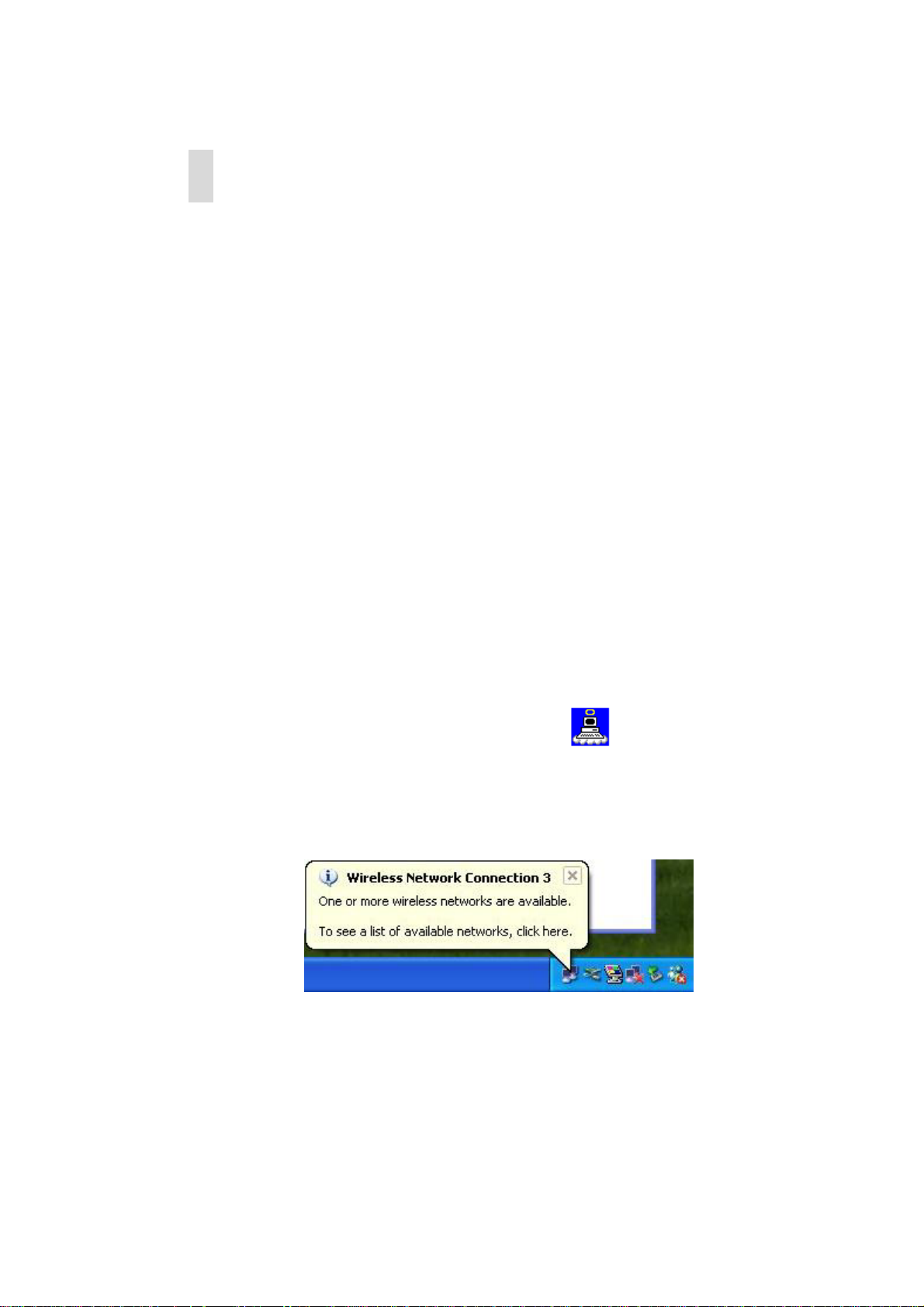
2. Windows XP will appear a “Wireless Network Connection # ” message.
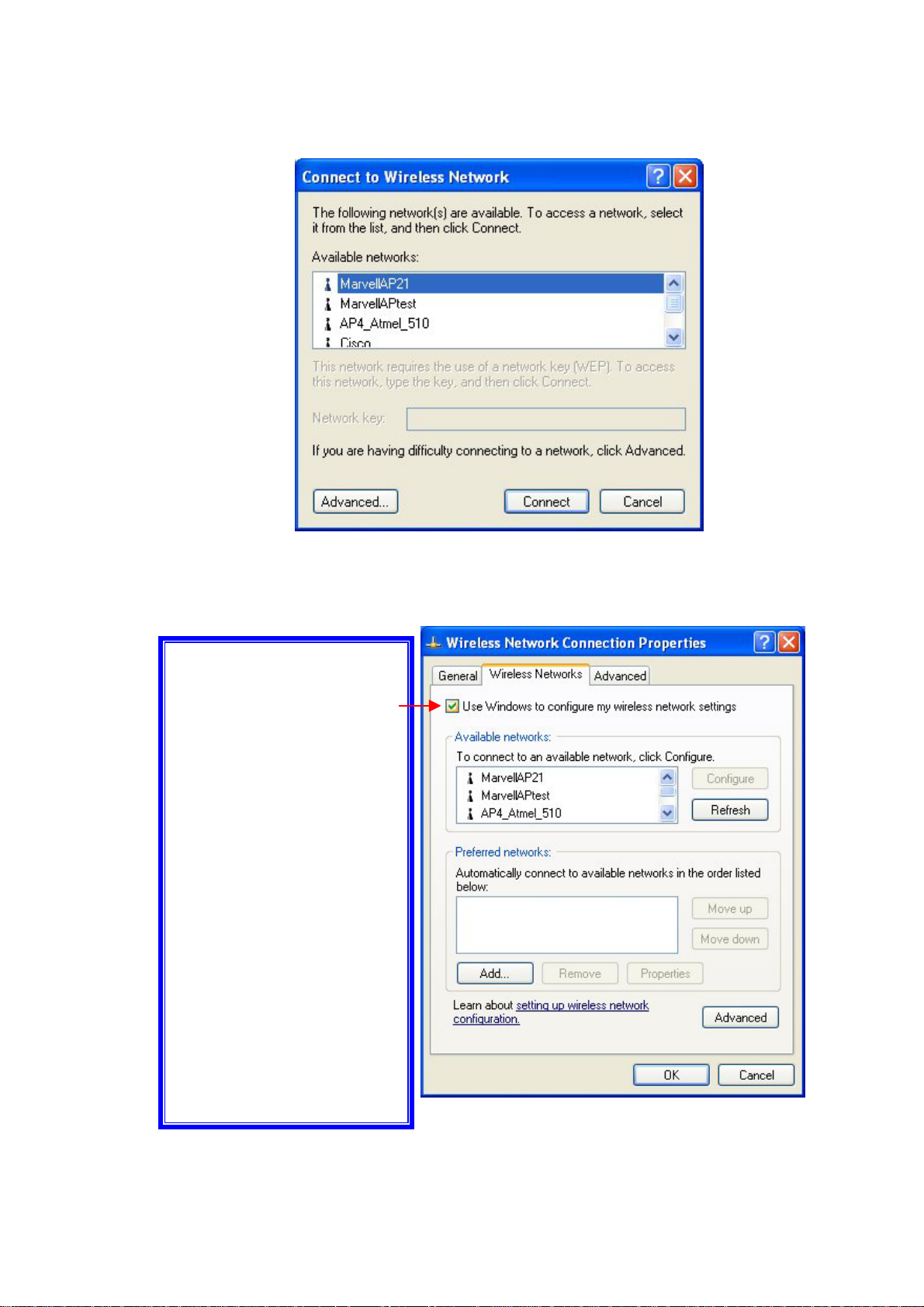
3. Click on the message and the “Automatic Wireless Network Configuration”
will display automatically. You may click “Connect” button to connect with
an available Access Point.
- 30 -
Page 32
A
y
4. You also may click “Advanced” button to make advanced configuration for
the 802.11b Wireless LAN CardBus Adapter, Select the Wireless Networks
tab shown as below.
Note: You must select
one way to configure
802.11b Wireless LAN
CardBus Adapter either
of using the
Configuration and
Monitor Utility by
un-checking this check
box or using Windows XP
utomatic Wireless
Network Configuration
first by checking this
check box. When using
the Configuration and
Monitor Utility, the check
box will be un-checked
automaticall
- 31 -
.
Page 33
For more information on how to use the automatic wireless network configuration, please
refer to Windows XP Help file.
However, the Configuration & Monitor utility provides you more settings to configure the
802.11b Wireless LAN CardBus Adapter and monitor the wireless network connection.
Please refer to the following section “Usage of the Configuration & Monitor utility”.
5.2 Usage of the Configuration & Monitor Utility
1. Insert the 802.11b Wireless LAN CardBus Adapter into the PCMCIA slot on
the laptop. The Configuration & Monitor Application utility will appear as an
icon on the system tray of Windows task bar. Double-click on this
icon or go to Program File and run the CardBus Wireless LAN.
When the station is in Infrastructure mode and not associated with an AP,
color of the icon is red.
When the station is in Infrastructure mode and associated with an AP, color of
icon is blue.
When the station is in Ad-Hoc mode, color of icon is always blue.
When the station is in Ad-Hoc mode and the WLAN Card is resetting and
initializing, color of icon is red.
2. The next window appears on screen (the following pages describe the
Configuration & Monitor Application utility in sequence).
- 32 -
Page 34
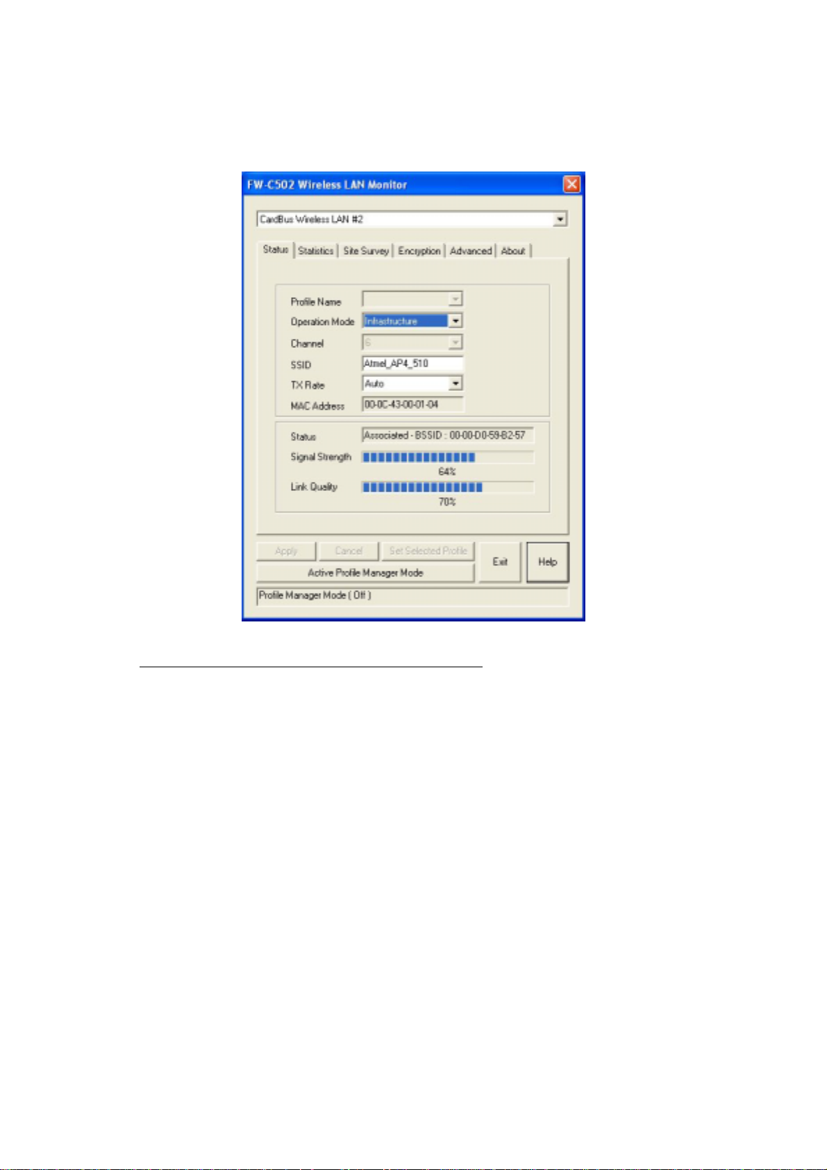
Status
The following configuration parameters are shown:
Profile Name
The Profile field allows you to set values for all parameters by selecting a
previously defined profile or allows you to create a new profile for 802.11b
Wireless LAN CardBus Adapter. To create a new profile, enter a Profile
Name in Profile field and set the corresponding parameters. After complete
the setting, click “Set Selected Profile” and click “Apply” button to take
effect. If you don’t want to use the profile, click the “Cancel Profile
Manager Mode”. You could have multiple profiles and modify a profile at
any time.
Operating Mode
Allows you to choose between Ad-Hoc or Infrastructure mode. In Ad-Hoc
mode the wireless stations can communicate directly with each other. In
Infrastructure mode the use of an Access Point (AP) is necessary for
wireless stations to communicate with each other.
- 33 -
Page 35

Channel
This item is available only if Ad-Hoc mode was selected in the previous field.
Select the 14 channels available for use.
SSID
When using the wireless station in an Ad-Hoc mode then all participating
stations should have the same SSID. When using the wireless station in an
Infrastructure mode the SSID must be the same as the SSID of the AP it is
associated with.
Tx Rate
Your WLAN Card provides various transmission (data) rate options for you to
select. In most networking scenarios, the option Auto will prove the most
efficient. This setting allows your WLAN Card to operate at the maximum
transmission rate. When the communication quality drops below a certain
level, the WLAN Card will automatically switch to a lower transmission rate.
Transmission at lower data speeds is usually more reliable. However, when
the communication quality improves again, the WLAN Card will gradually
increase the transmission rate again until it reaches the highest available
transmission rate. If you wish to balance speed versus reliability, you can
select any of the available options.
MAC Address
Indicates the MAC address of the 802.11b Wireless LAN CardBus Adapter.
MAC address could be used as the unique ID of the WLAN Card.
The communication status is also shown:
Status
Indicates the status of connection and MAC address of the associated Access
Point when the FW-C502 802.11b Wireless LAN CardBus Adapter is
configured in Infrastructure mode.
Signal Strength
Signal level when receiving the last responding packet. Signal strength is
calculated as the percentage of its signal level measurement relative to the full
signal level.
- 34 -
Page 36
Link Quality
The transmission quality between your WLAN Card and the AP it is associated with
(Infrastructure mode). Based on the quality of the received signal of the Access Point
beacon.
After changing parameters, click the Apply button to take effect.
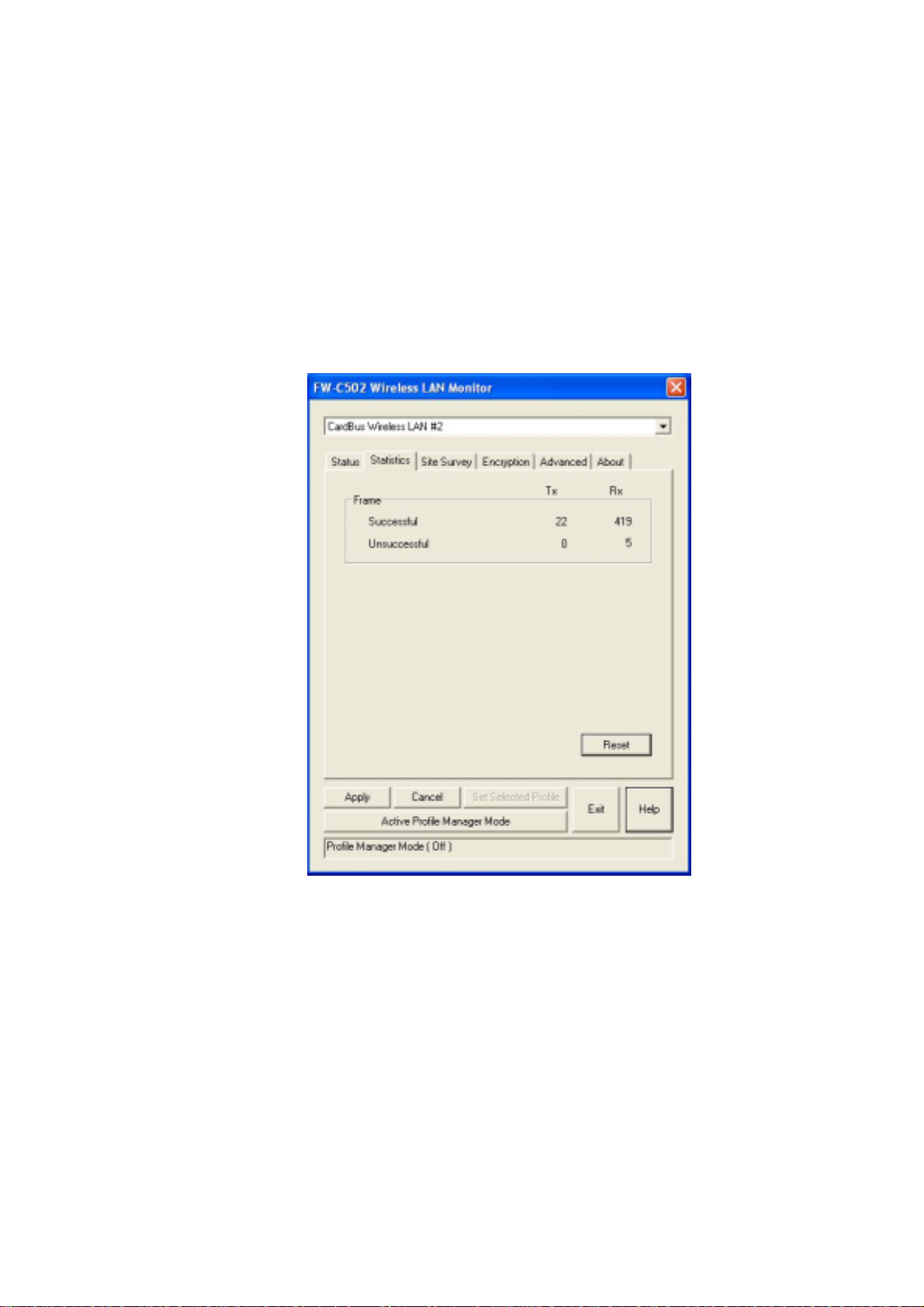
Statistics
The Statistics utility allows you to view the statistic (Packets) information (Data
Packets, Mgmt Packets, and Rejected Packets). To renew or update the list of
statistics, press “Reset”.
- 35 -
Page 37
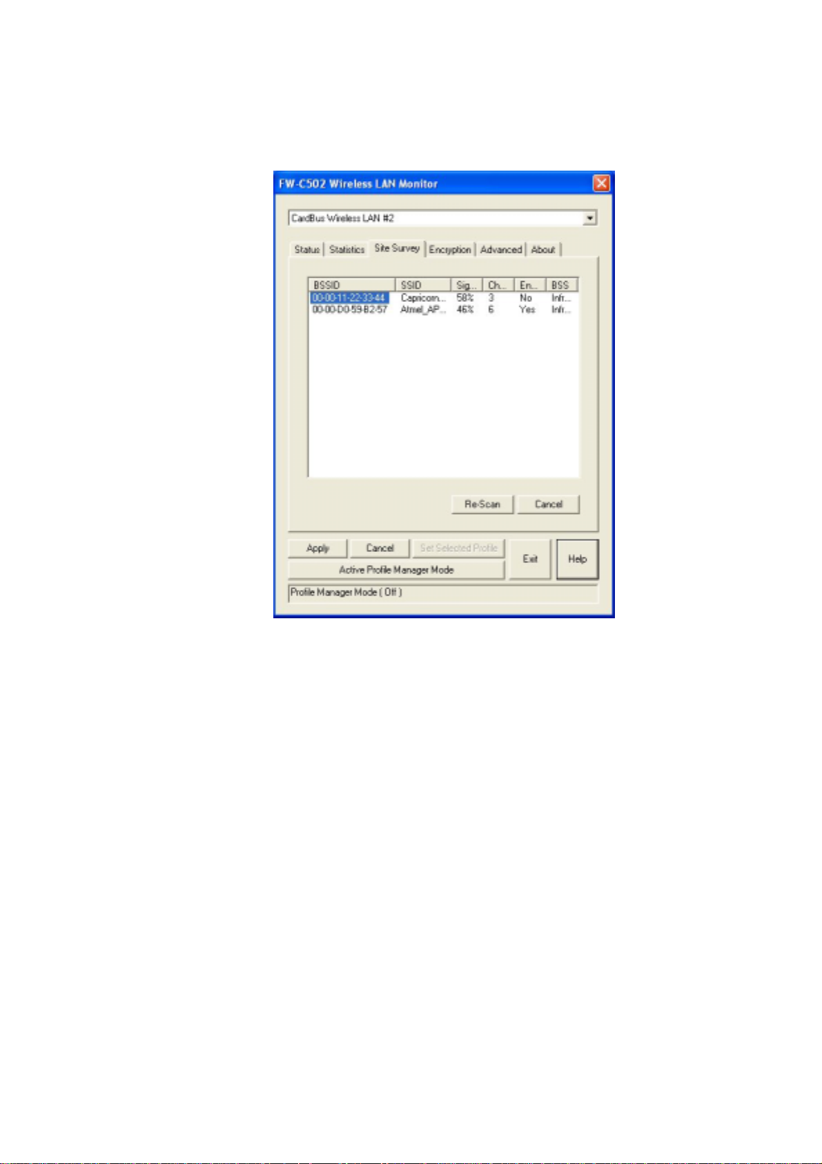
Site Survey
The Site Survey utility allows you to scan all the channels to locate all the APs
(Access Points) within the range of your WLAN Card. When an/various AP(s)
are located, information regarding the BSSID and SSID, signal strength and
channel where the AP operates, whether or not WEP encryption is used, and the
operating mode is shown. Click “Re-Scan” to update the list. You may stop
rescanning by press the “Cancel” button.
To associate with any of the APs listed, double-click on your choice (on the
BSSID field) and the utility will take you back to the Status utility showing you
the parameters of the newly established connection.
- 36 -
Page 38
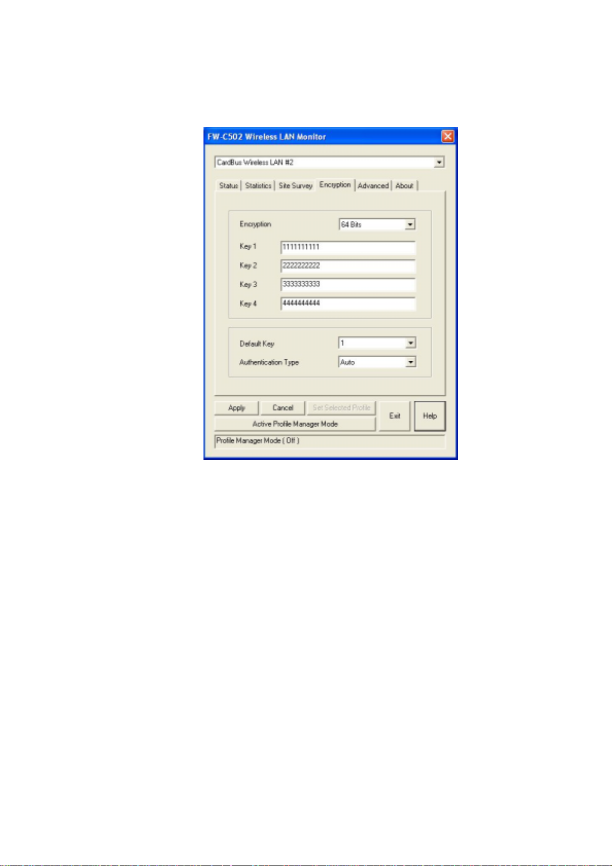
Encryption
To prevent unauthorized wireless stations from accessing data transmitted over
the network, the Encryption utility offers highly secure data encryption by
allowing you to set four different WEP keys (must be the same for the
participating wireless stations) and specify which one to use. To set encryption:
1. Choose Enabled on the Encryption window and select either 64 Bits or 128 Bits
Encryption.
2. Select any of the available WEP keys (Key #1 to #4) on the Default Key field.
The WEP keys must be in HEX (hexadecimal) format in the range of a to f, A to
F, and 0 to 9.
3. Select the Authentication Type (Open System or Shared Key or Auto).
4. Press “Apply” for any changes to take effect.
- 37 -
Page 39
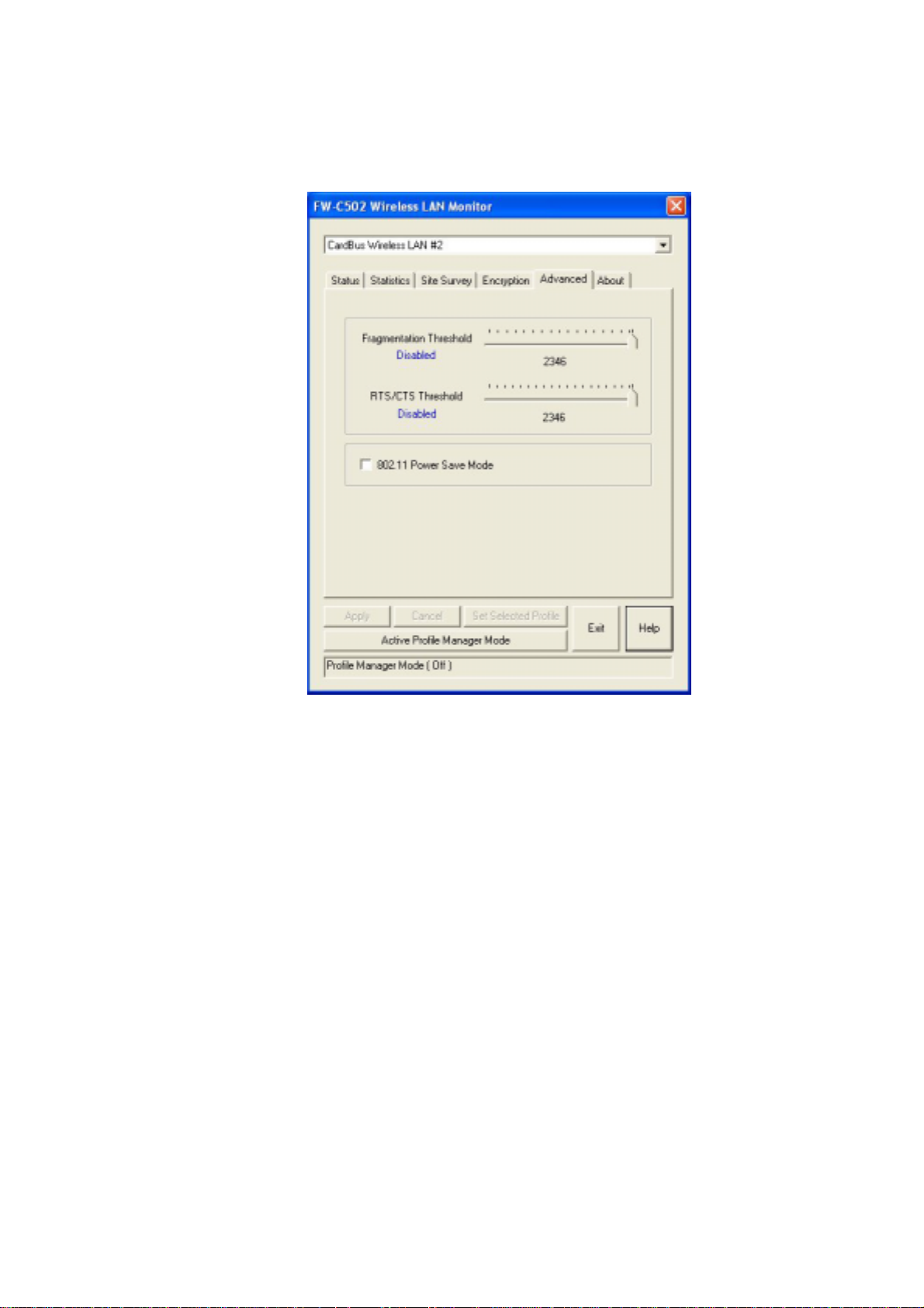
Advanced
The Advanced utility allows you to change the following advanced
configuration settings:
Fragmentation Threshold
Allows you to set the Fragmentation Threshold (threshold for the activation
of the fragmentation mechanism). The Fragmentation function is used for
improving the efficiency when high traffic flows along in the wireless
network. If you often transmit large files in the wireless network, move the
slide bar with your mouse and then use the right and left arrow keyboard
keys to select an exact number. The figure shows the recommended
configuration setting.
RTS/CTS Threshold
Allows you to set the RTS Threshold (threshold for the activation of the
RTS/CTS mechanism). Transmitter contending for the medium may not hear
- 38 -
Page 40
each other. RTS/CTS (Request-To-Send/Clear-To-Send) mechanism can
solve this “Hidden Node Problem.” If the packet size is smaller than the preset
RTS Threshold size, the RTS/CTS mechanism will not be enabled. To enable
RTS/CTS Threshold, move the slide bar with your mouse and then use the
right and left arrow keyboard keys to select an exact number. The figure
shows the recommended configuration setting.
802.11 Power Save
Allows you to minimize power consumption and conserve the battery life of
your computer.
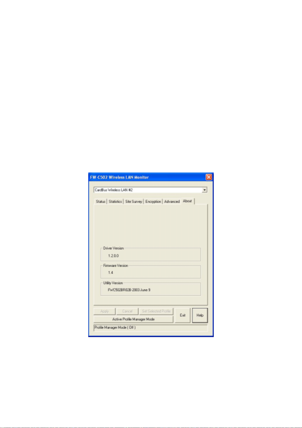
About
By choosing this option, you can get the information on the version of the
driver, firmware and application. Use the “Exit” button in order to exit the
application.
On a Local Area Network (LAN) or other network, the MAC (Media Access
Control) address is your computer’s unique hardware number. On an Ethernet
- 39 -
Page 41
LAN, it is the same as your Ethernet address.
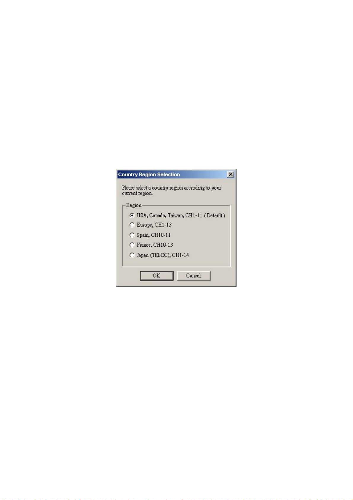
5.3 Usage of the Change Region Tool
This option is used for changing the Channel of the Region for the WLAN Adapter
according to your current region. The default Channel will be Channel 1 to Channel 11 for
USA, Canada and Taiwan. If you don’t locate in the default countries, please go to the
FW-C502 Change Region Tool and select the Channel Region that you locate. If you don’t
select the right Channel Region, it may occur your WLAN Adapter cannot work properly.
After selecting the correctly Region, click “OK” button to make the Change Region take
effect.
- 40 -
Page 42

6 Troubleshooting
This chapter covers potential problems you may run into and the possible
remedies. After each problem description, some instructions are provided to
help you to diagnose and solve the problem.
Q: When you encounter problems, there are some preliminary
checklists that can help you to dig out the problems before you take
further actions?
A: - Try to isolate which part of the computer’s network connection is causing
the problem.
- Absence of, or conflict of the WLAN Card driver. Make sure that all device
drivers are correctly installed (refer to chapter 3).
- Determine if the location of your WLAN Card is not conducive for
wireless transmission (refer to chapter 2 “Site Selection”).
If a problem persists after you follow the instructions in this chapter, contact
an authorized dealer for help.
Q: When you encounter problems during Installation?
A: Don’t insert your WLAN Card into the PCMCIA slot until you have
finished the installation. If in case you should mistakenly insert your
WLAN Card into your computer before installing the driver and utility,
then perform the following to correct it:
– Remove the WLAN Card from the PCMCIA slot.
– Insert the driver CD into the CD-ROM drive and double-click the file
SETUP.EXE under the Windows directory. It would locate the already
installed driver and utility and uninstall it.
– Re-boot your system after uninstalling.
– Refer to chapter 3 and follow the instructions to properly install the
driver and utility before inserting the WLAN Card.
Re-insert the WLAN Card to the computer again.
Check if the I/O and IRQ for the WLAN Card have conflict problems with
other devices connected to your computer.
- 41 -
Page 43

For Windows 98SE / 2000 / Me operating system, make sure that the
PCMCIA device driver is installed on your computer.
Q: During using Configuration & Monitor Utility, when you encountered
the problem to connect?
A: - Use the Monitor utility of your Configuration & Monitor Utility to
check the Link Quality of your WLAN Card with the AP it is associated
with (Infrastructure mode) or with other wireless station(s) (Ad-Hoc mode).
- Use the Site Survey utility of your Configuration & Monitor Utility to
check if there is high interference around the environment.
Q: When you cannot connect with Access Point?
A: - Make sure that the Access Point that your WLAN Card is
associated with is powered on and all the LEDs are working
properly.
- Reconfigure and reset the Access Point.
- Use the Web Manager / Telnet of the Access Point to check whether it
is connected to the network.
Q: When Infrastructure mode is configured, the WLAN card cannot
communicate with the computer in the Ethernet?
A: - Make sure that the Access Point your WLAN Card is associated with is
powered on.
- Use the Site Survey utility of the Configuration & Monitor Utility to
verify if the operating radio channel is in good quality. Or, change the
Access Point and all the wireless station(s) within the BSSID to another
radio channel.
- Out-of-range situation, which prevents the WLAN Card from establishi ng
a wireless connection with the network. Move the WLAN Card closer to the
Access Point it is associated with.
- Make sure that your WLAN Card is configured with the same security
option (encryption) to the Access Point.
- 42 -
Page 44

- Make sure that the BSSID is the same as the Access Point for a
roaming-disabled wireless station, or the ESSID is the same as the Access
Point for a roaming-enabled wireless station.
Q: What should I do when I cannot access the network?
A: - Make sure that the necessary driver(s) was correctly installed.
- Make sure that the network configuration is appropriate.
- Make sure that the user name or password is correct.
- You have moved out of range of the network.
- Turn off power management.
Q: When the Configuration & Monitor Utility does not work correctly.
A: - Make sure that the Configuration & Monitor Utility is correctly installed
(refer to chapter 5).
- If you are sure the operation has stop, reset the computer.
- 43 -
Page 45
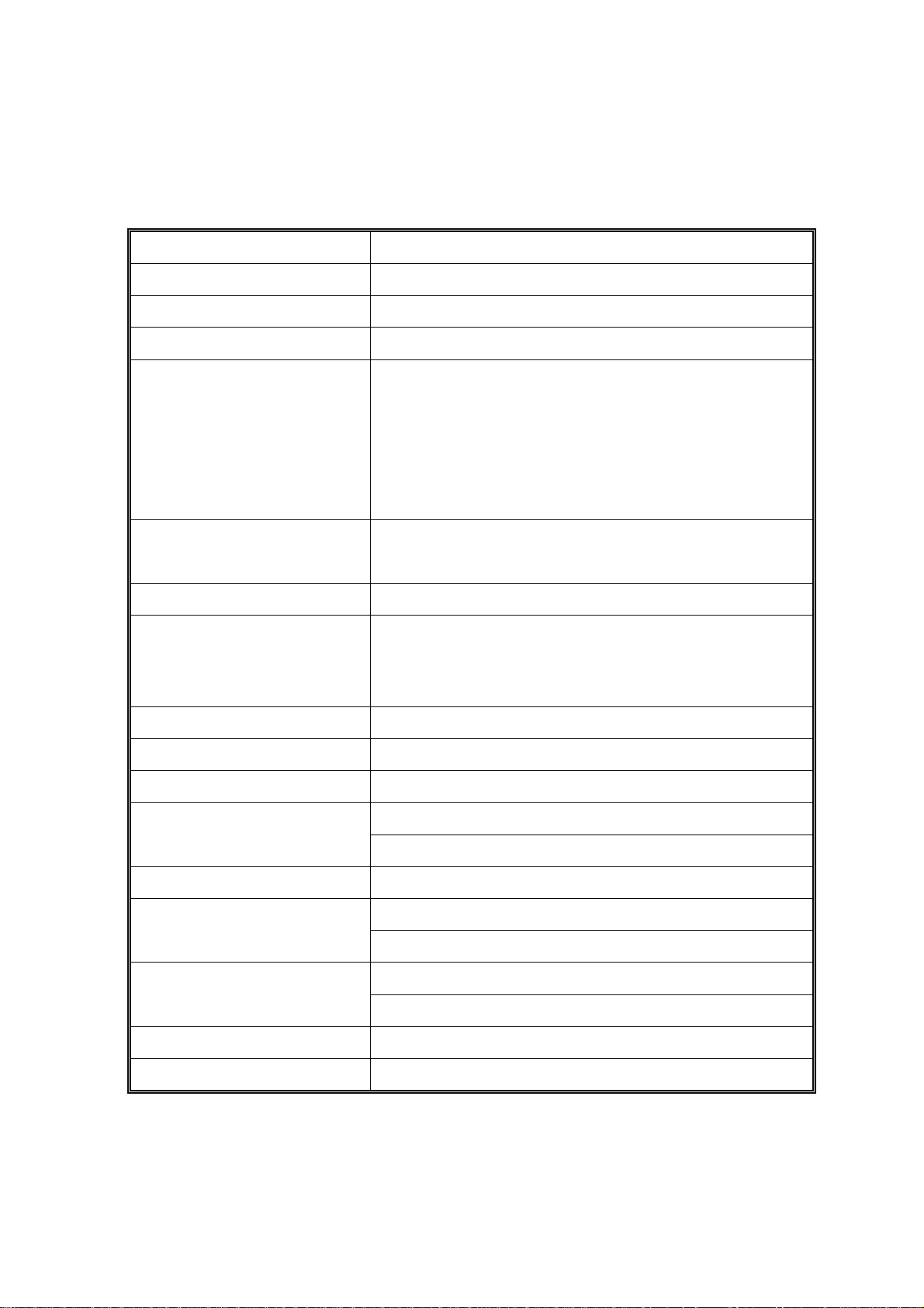
Appendix A WLAN CardBus Adapter
Specification
Product 802.11b Wireless LAN CardBus Adapter
Model FW – C502
Attach Interface/ bus PCMCIA Type II
LED Indicators LINK and PWR
2.412 ~ 2.462 GHz (FCC, Canada), 11 Channels
2.412 ~ 2.4835 GHz (Japan, TELEC), 14 channels
Operating Frequency/Channel
RF Modulation
RF Output Power 11 dBm typical
Sensitivity
Data Rate 11, 5.5, 2, 1 Mbps with automatic fall back
Media Access Protocol CSMA/CA + ACK, IEEE 802.11b compliant
Working Mode Ad-Hoc, Infrastructure
Power Consumption
Physical Dimension 119(mm) x 54.0(mm) x 5.0(mm)
2.412 ~ 2.472 GHz (Euro ETSI), 13 channels
2.457 ~ 2.462 GHz (Spain), 2 channels
2.457 ~ 2.472 GHz (France), 4 channels
Direct Sequence Spread Spectrum (DSSS) Technology
CCK, DQPSK, DBPSK
-80 dBm at 11Mbps
-82 dBm at 5.5Mbps
-87 dBm at 2Mbps
-88 dBm at 1Mbps
TX: 3.3 V, 420 mA
RX: 3.3 V, 350 mA
20% to 70% in operating
Humidity
20% to 90% Non-condensing in storage
0 ~ 55 degree C in operation
Temperature
-20 ~ 70 degree C in storage
Driver Support Windows 98SE/ ME/2000/XP
Electromagnetic Compatibility FCC, CE
- 44 -
 Loading...