


USER’S MANUAL AND INSTRUCTIONS


Index
1. Introduction
2. Drivetrain Parts
3. Tools and Supplies
4. Frame Preparation
4.1.RD Cable Routing
4.2.FD Cable Routing
4.3.Bottom Bracket Mounting
5. Drivetrain Installation
5.1.FD Installation
5.2.RD Installation
5.3.Shifter Installation
5.4.Battery Installation
5.5.Chain Installation
6. Pairing
7. Usage and Adjustments
7.1.Power ON
7.2.Power OFF
7.3.Rear Derailleur Alignment
7.4.Front Derailleur Alignment
7.5.Limit Screw Adjustment
7.6.B-tension Screw Adjustment
8. Battery Diagnostic
8.1.Main Battery
8.2.Shifter Battery
9. Battery Charging
9.1.Shifter Battery Replacement
10. Diagnostics
11. Battery Warning
12. Important Information

1. Introduction
Congratulations on your Full Speed Ahead product. Please read these instructions and follow them for correct
use. Failure to follow the warnings and instructions could result in damage to product not covered under
warranty, damage to bicycle; or cause an accident resulting in injury or death. Since specific tools and
experience are necessary for proper installation, it is recommended that the product be installed by a qualied
bicycle technician. FSA assumes no responsibility for damages or injury related to improperly installed
components.
2. Drivetrain Parts
FSA K-Force WE is an electronic hybrid drivetrain. It is dened as hybrid because is not completely wireless.
Indeed, there are no wires from shifters to derailleurs but the communication between the two derailleurs is
still effectuated using wires.
The different parts of the drivetrain will be explained in this section.
•Main Battery
The main battery is placed into
the seatpost and provides power
to the two derailleurs through
two wires.
•Shifters
Shifters wirelessly communicate
with derailleurs. They have their
own coin cell batteries, located
inside the housing.
•Front and Rear Derailleur
•Wires
Two internally routed wires,
one longer and one shorter,
connect front and rear
derailleurs to the battery.

3. Tools and Supplies
FSA recommends installation of WE Drivetrain to be performed by a highly experienced bicycle mechanic.
The following tools and supplies are needed for correct installation
of FSA WE Drivetrain. See tool list below:
• Hex wrench sizes (1.5 mm, 2 mm, 5 mm)
• Torque wrench (2-14 Nm range)
• Phillips screwdriver size PH2
• FSA cable guide tool
• 11sp compatible chain rivet tool
• Light grease
FSA recommends using the following protective equipment for
your own safety:
• Protective glasses
• Latex or Nitrile gloves
4. Frame Preparation
Before to start assembling the drivetrain you will have to insert the wires for Front Derailleur FD and Rear
Derailleur RD inside your frame. Any frame compatible with DI2 internal wire specication will be compatible
also for WE wire routing.
RD Wire Routing
Insert the wire guide tool in the rear chainstay to the BB shell as per picture below
Connect the RD wire to the female plug
of the wire guide tool.
Unplug the wire guide and slide it inside
the seat tube from the BB shell as per
picture below.
Pull the wire guide to thread the RD wire
inside the rear chainstay
Connect the wire to the wire guide tool
and pull up through the seat tube.

FD Wire Routing
Slide the wire guide tool through the FD
routing hole into the seat tube.
Connect the FD wire and pull up through
the seat tube.
Bottom Bracket and Crankset mounting
For BB and crankset mounting, check the dedicated FSA instructions.
5. Drivetrain Installation
Before assembling the drivetrain, install Front Derailleur (FD) and Rear Derailleur (RD) wires. WE wires are
compatible with industry standard internal wire routing.
FD Installation
1 2 3
Install the front derailleur on frame
braze-on using supplied.
End of sentence in point 1. Snug
the bolt enough to hold derailleur
in position.
Adjust the derailleur height so the
gap between outer cage and large
chainring is 1 to 3 mm. See image
3
4 5
When gap is set, rotate the
derailleur so the cage position is
parallel with the chainrings. See
image 4
When derailleur position is correct,
tighten the derailleur bolt to 5-7
Nm.

RD Installation
Rear derailleur must not be forced out of position during installation. Install RD in it set position.
Avoid interference between pulleys or B-tension screw and the dropout during installation.
1
Apply a small amount of grease on
the derailleur hanger threads
Shifters Installation
Install the shifter on the handlebar as shown
in image 1. Position the shifter according to
preference.
Install the brake cable and housing.
2
Using a 5 mm hex wrench, screw
the derailleur in to the hanger.
Tighten the derailleur bolt to 5-7
Nm.
Roll the shifter hood forward to expose the shifter
clamp bolt. Tighten the bolt with a 5 mm hex
wrench to 6-8 Nm.
Adjust the lever reach using a 2mm hex wrench,
as shown in image.

Battery Installation
1 2 3
Insert battery in the battery
adaptor.
Fully insert the battery and adaptor
in the seatpost and check that it is
secure.
Chain Installation
Follow below instruction depending on which cage you use on rear derailleur.
Using short cage
To adjust chain length, use the following procedure if your rear derailleur is mounted with short cage.
1. Install the chain around the big chainring and smallest cog. Route it through rear derailleur cage.
2. In this position, bring the two ends of the chain together until the derailleur cage is vertical.
This is the correct chain length.
3. Use a chain tool to cut the chain to the correct length
Using long cage
To adjust chain length, use the following procedure if your rear derailleur is mounted with long cage.
1. Install the chain around the big chainring and the biggest cog.
2. Pull the chain tight over these two cogs and add one full link (one outer and one inner).
This is the correct chain length.
3. Use a chain tool to cut the chain to the correct length.
Chain lock
If it has not already be done, route the chain through rear derailleur cage.
Follow below operating list for install the Drive Link and lock the chain
1. Insert the plates of the Drive Link on opposing sides of each chain end. (Fig.1) Insert and hook Drive
Link pins into the opposite plate. (Fig.2)
2. To snap Drive Link in locked position, rotate crank until Drive Link is above the chainstay. Hold the rear
brake and rmly push the crank forward. (Fig.3)
Plug the derailleur wires in to the
battery terminal leads. Either lead
can work for either wire.
Make sure Drive Link snaps in to locked position before use.

To unlock the chain for replacement or other operation, follow below instructions:
1. To disconnect the Drive link, isolate the link. (Fig.4)
2. Firmly squeeze the link bushings together so that the pins and plates decouple. (Fig.5)
3. Pull the plates apart. (Fig.6)
Drive Link cannot be reused if removed. Use a new Drive Link to reassemble.
6. Pairing
Follow the procedure below for new shifter pairing:
1 2
With the drivetrain on, push the SET button until
both LEDs illuminate green –the system is now in
SET mode.
Roll the shifter hood forward to expose the
transmitter cover.
3 4
To put the shifter in pairing mode push and hold
the pairing switch and simultaneously push either
shifter button.
When the shifter enters pairing mode, the pairing
button will illuminate red.

6
When pairing is complete, the red LED on the
shifter will blink and turn off. The pairing is
complete.
5
With the shifter in SET mode, press the Power
button on the FD until both the LEDs illuminate
blue.
7. Usage and Adjustments
Power On
Push and hold the power button. The LED lights will blink
red-blue. When the LED lights ash blue, WE is on.
Release the power button. Push each shift button once to
activate them.
Power Off
Push and hold the power button. The LED lights will blink
blue-red. When the LED lights ash red, WE is off.
WE will also go in to Stand-By mode, and turn off
automatically after a period of inactivity. Those intervals
are customizable in the WE Dashboard Software.
Rear Derailleur Alignment
1. Shift the chain to the small chairing.
2. Shift the rear derailleur to the center (6th) cog.
3. Enter set mode by pushing and holding the SET button
for 2 seconds. Both LEDs will blink green.
4. Press rear shifter button to enter the rear derailleur
adjustment mode (by factory default is the right one but
you can change it in the WE Dashboard Software.)
In this mode, the rear derailleur will operate in micro-
steps.
5. Set the rear derailleur zero position:
a. Rotate the crank and micro-shift the rear derailleur
up until the chain begins to rub on the next cog.
b. Move the RD three micro-steps back.
c. Double check the alignment — The upper jockey
pulley on the rear derailleur should be in line with the
center cog.
6. Exit set mode---push and hold the SET button for 2
seconds. The green light will stop blinking and the rear
derailleur zero position will be saved.
7
Repeat the procedure for the other shifter.

Front Derailleur Alignment
1. Shift the rear derailleur to the center (6th) cog.
2. Enter set mode by pushing and holding the SET
button for 2 seconds. Both LEDs will blink green.
3. Press either front shifter button to enter the
front derailleur adjustment mode (by factory
default is the left one but you can change it in
the WE Dashboard Software).
4. The front derailleur will move in to the gear
selected.
5. Micro-adjust the front derailleur position using
the REAR shifter. Shift between chainrings using
the front shifter.
a. Big chainring adjustment: Using the REAR
shifter, adjust the derailleur cage plate position.
Ensure 1mm of clearance (not more) between the
outer derailleur cage plate and the chain.
b. Small chainring adjustment: Using the REAR
shifter, adjust the derailleur cage plate position.
Ensure approximately 1mm (not more) of clearance
between the inner derailleur cage plate and the chain.
6. When both inner and outer positions are adjusted
properly, exit set mode---push and hold the SET button
for 2 seconds. The green light will stop blinking and the
front derailleur zero position will be saved.
Limit Screws Adjustment
After both derailleurs alignment it is needed to proceed
with the limit screws adjustment. There are two screws for
upper and lower position, positioned in the back of the rear
derailleur.
Upper Position Adjustment
To adjust the upper position limit, shift the rear derailleur
to the largest cog. Then tighten the upper position screw
(outermost screw) until it touches the internal stop. Back
the limit screw off a half-turn.
Lower Position Adjustment
To adjust the lower position limit, shift the rear derailleur
to the smallest cog. Then tighten the lower position screw
(innermost screw) until it touches the internal stop. Back
the limit screw off a half-turn.
Do not tighten the limit screw against its stop. Tightening
may result in reduced performance or damage to RD
internals.

B-Tension Screw Adjustment
B-tension screw adjustment must be set after all derailleur
and limit screw adjustments. B-tension screw adjustment
optimizes the distance between the upper jockey pulley and
cassette cogs.
To adjust the B-tension, shift the rear derailleur to the largest
cog.
Use a phillips screwdriver to make the following adjustments:
• Turn the screw clockwise to increase repetition pulley and
the cog.
• Turn the screw counterclockwise to decrease the space
between pulley and the cog.
For optimal shifting, move the pulley as near as possible to
the cog without making contact.
When B-tension is set, double check RD functionality and
adjustment. If RD need adjustment, repeat the adjustment
process.
8. Battery Diagnostics
WE uses three batteries. The main battery powers the front and rear derailleurs. Each shifter is powered by a
CR2032 coin cell battery.
Main battery
When WE is on, the LED 1 on the main control unit will blink every 3 seconds (customizable by We Dashboard
App). Main battery level is indicated by the following LED color codes:
LED Color Battery Level Action
Blue 77-100% Battery level is high, no action necessary.
Green 23-77% Battery level is OK, charge when convenient.
Yellow 0-23% Charge as soon as possible.
Red 0%
Charge battery immediately. FD does not work anymore. You only have
1000 shift on RD.

Shifter battery
The shift batteries are CR2032 coin cell batteries and are
not rechargeable. When the battery level is low, they must be
replaced. It is not necessary to replace both batteries at the
same time if they are not both showing a low charge.
Each time a shift button is pressed a corresponding LED
will blink on the main controller. LED 1 blinks for the right
shifter, LED 2 blinks for the left shifter. The color of the LED
will be related to the level of the battery.
LED Color Battery Level Action
Blue 77-100% Battery level is high, no action necessary.
Green 23-77% Battery level is OK.
Yellow 0-23% Replace battery as soon as possible.
Red 0% Replace battery immediately. The Shifter will stop to work.
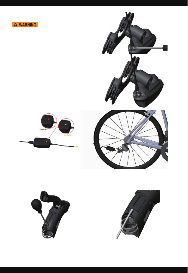
9. Battery Charging
Turn WE off before charging the battery.
1. Use 1.5mm hex wrench to unscrew the
rear derailleur wire clamp.
2. Unplug the wire from the rear derailleur.
3. Plug the wire in to the WE charger,
then plug the charger in to outlet.
The charger light will be red while charging and turn
to green at full charge.
Note: The CR2032 batteries used in each shifter are
not rechargeable. They will last for a long service
interval and must be replaced when spent. See
below battery diagnostics for details.
3
Shifter battery replacement
Follow the procedure below for shifter battery replacement:
1
2
Roll shifter hood forward and loosen the cover
screw.
Insert a small flat blade screwdriver in the slot
shown in the illustration and pry the cover up.

Once the cover is partially open insert the screw
driver from the side to completely remove the
cover.
Remove the coin cell battery from the holder and
install new battery.
Make sure to respect correct polarity.
Reinstall the cover and reposition the hood on the
housing.
If the other shifter battery is low, repeat the
procedure for replacement.
10. Diagnostics
LED Indication Issue Action Remedy
Both LEDs red steady on Front derailleur stall
Both LEDs yellow steady on Rear derailleur stall
LED 1 green and LED 2 red
steady on
LED 1 red and LED 2 green
steady on
Communication absence
between front and rear
derailleur
Failed reply from rear
derailleur to front derailleur
at end of movement.
Probable loss of rear
derailleur position
• Check that the derailleur
is mounted correctly
• Check the SET point
• Check that the derailleur
is mounted correctly
• Check the SET point
• Check connections of both
derailleurs.
• Check wires for damage
• Check the connection of
both derailleurs connector.
• Check the SET point

11. Battery Warning
Battery
1. Be sure to use only with FSA charger and follow charging instructions.
2. Do not crush and/or do not puncture the battery.
3. If the battery pack is stored for a long time, the battery pack’s storage should be 7.8V~8.0V.
4. Charging
Charging Current
The charging current should be less than the maximum charge current specied in the Product
Specication. Charging with a higher current than the recommended value may cause damage
to cell/battery pack’s electrical, mechanical and safety performance and could lead to heat
generation or leakage.
Charging Temperature
The cell should be charged within a 0°C~45°C (32°-113°F) range in the Product Specication.
Prohibition of Reverse Charging
Reverse charging is prohibited. The cell/battery pack should be connected correctly. The
polarity has to be conrmed before wiring. In case the cell/battery pack is connected improperly,
the cell/battery pack cannot be charged. Likewise, reverse charging may cause damage to the
cell/battery pack which may lead to degradation of the cell/battery pack performance, affect
the cell/battery pack safety and could cause heat generation or leakage.
5. Discharging
Discharging Current
The cell should be discharged at less than the maximum discharge current specied in
the Product Specication. A high discharging current may reduce the discharging capacity
signicantly or cause over-heating.
Discharging Temperature
The cell should be discharged within a -20°C~60°C (-4°-140°F) range specied in the Product
Specication.
Over-Discharging
It should be noted that the cell/battery pack would be in an over-discharged state by its self discharge characteristics if the cell/battery pack has not used for long time. In order to prevent
over-discharging, the (individual) cell should be charged periodically to maintain between 7.8V
and 8.0V
Over-discharging may cause loss of cell/battery pack performance, characteristics, or battery
functions.
6. Storage
The cell/battery pack should be stored within a -10°C~45°C (14°-113°F) range.
7. Long Time Storage
If the battery pack is stored for a long time, the battery pack’s storage should be 7.8V~8.0V.

Instructions for “long term storage”:
a. Long-term storage can accelerate battery self-discharge and lead to the deactivation
of the batteries. To minimize the deactivationt, store battery packs in a temperature range
of -10°C~45°C (14°-113°F).
b. When charging for the rst time after long-term storage, deactivation of the packs may have
led to decreased capacity. To recover the packs to original performance, repeat several
cycles of fully charging and discharging.
c. When storing the pack for more than 6 months, please charge at least once every 6 months
to prevent leakage and deterioration in performance due to self-discharging.
8. Others
Do not drop, hit or bend the battery body.
Battery electrolyte is harmful
The battery should not have any electrolyte liquid visibly owing. In case lectrolyte comes
into contact with the skin or eyes, ush/wash the electrolyte immediately ith fresh water and
immediately seek medical attention.
Prohibition of dumping of cells into re
Never incinerate nor dispose the cells in re. This may cause a dangerous explosion and is
prohibited.
Prohibition of cells immersion into liquid such as water
The cells should never be soaked with liquids such as fresh water, seawater or drinks such as
soft drinks, juices, coffee, etc.
Battery cells replacement
The battery replacement shall be done only by either the battery cell supplier or device supplier
and never be done by the user.
Prohibition of use of damaged cells
The cells might become damaged during shipping by shock. If any abnormal features of the
cells are found - such as damage to the plastic envelope of the cell, deformation of the cell
package, smelling of electrolyte, electrolyte leakage or other abnormal appearance, the cells
should not be used.
The cells with a smell of the electrolyte or a leakage shall be placed away from re to avoid
explosion.

12. Important Information
Risk of explosion if battery is replaced by an incorrect type. Dispose of used batteries according to the
instructions
If your device endures electrostatic discharge, it may automatically reboot and disconnect current wireless
transmission. You will need to manually reset the wireless connection when this happens.
Use your device in temperature between -5˚C ~ 40˚C. Exposing your device to extremely low or high
temperatures may result in damage, malfunction, or even explosion.
FCC Compliance Statement
This device complies with part 15 of the FCC Rules. Operation is subject to the following two conditions: (1)
This device may not cause harmful interference, and (2) this device must accept any interference received,
including interference that may cause undesired operation.
Changes or modications not expressly approved by the party responsible for compliance could void the user‘s
authority to operate the equipment.
This equipment has been tested and found to comply with the limits for a Class B digital device, pursuant
to part 15 of the FCC Rules. These limits are designed to provide reasonable protection against harmful
interference in a residential installation. This equipment generates, uses and can radiate radio frequency
energy and, if not installed and used in accordance with the instructions, may cause harmful interference
to radio communications. However, there is no guarantee that interference will not occur in a particular
installation. If this equipment does cause harmful interference to radio or television reception, which can be
determined by turning the equipment off and on, the user is encouraged to try to correct the interference by one
or more of the following measures:
—Reorient or relocate the receiving antenna.
—Increase the separation between the equipment and receiver.
—Connect the equipment into an outlet on a circuit different from that to which the receiver is connected.
—Consult the dealer or an experienced radio/TV technician for help.
FCC RF Exposure Information
This device is designed and manufactured not to exceed the emission limits for exposure to radio frequency (RF)
energy set by the Federal Communications Commission for an uncontrolled environment.
ISED Compliance Statement
This device complies with Industry Canada’s licence-exempt RSSs. Operation is subject to the following two
conditions:
(1) This device may not cause interference; and
(2) This device must accept any interference, including interference that may cause undesired operation of the
device.

Le présent appareil est conforme aux CNR d'Industrie Canada applicables aux appareils radio exempts de
licence. L'exploitation est autorisée aux deux conditions suivantes:
(1) l'appareil ne doit pas produire de brouillage, et
(2) l'utilisateur de l'appareil doit accepter tout brouillage radioélectrique subi, même si le brouillage est
susceptible d'en compromettre le fonctionnement."
CAN ICES-3(B)/NMB-3(B)
ISED RF Exposure Information
This equipment complies with Innovation, Science and Economic Development Canada RSS-102 RF exposure
limits set forth for an uncontrolled environment.
ISED Informations sur l'exposition RF
Cet équipement est conforme aux limites d'exposition RF RSS-102 d'Innovation, Sciences et Développement
économique Canada établies pour un environnement non contrôlé.
CE Compliance Statement
Maximum radio-frequency power transmitted in the frequency bands:
Model: FD-ED-8400
Bluetooth LE, 2402MHz~2480MHz: -5.8 dBm (e.i.r.p.)
ANT+, 2402MHz~2480MHz: -4.8 dBm (e.i.r.p.)
Model: SF-ED-8400
Bluetooth LE, 2402MHz~2480MHz: -4.1 dBm (e.i.r.p.)
ANT+, 2402MHz~2480MHz: -5.5 dBm (e.i.r.p.)
CE RF Exposure Information
This device meets the EU requirements and the International Commission on Non-Ionizing Radiation Protection
(ICNIRP) on the limitation of exposure of the general public to electromagnetic fields by way of health
protection.
Waste Electrical and Electronic Equipment (WEEE)
This symbol means that according to local laws and regulations your product and/or its battery
shall be disposed of separately from household waste. When this product reaches its end of
life, take it to a collection point designated by local authorities. Proper recycling of your product
will protect human health and the environment.
Hereby, [Tien Hsin industries Co., LTD] declares that the radio equipment type [FD-ED-8400 and SF-ED-8400] is
in compliance with Directive 2014/53/EU.
The full text of the EU declaration of conformity is available at the following internet address: www.address.
com/DoC.pdf
警語
NCC
本電池如果更換不正確會有爆炸的危險,請依製造商說明書處理用過之電池
廢電池請回收
經型式認證合格之低功率射頻電機,非經許可,公司、商號或使用者均不得擅自變更頻
率、加大功率或變更原設計之特性及功能。低功率射頻電機之使用不得影響飛航安全及
干擾合法通信;經發現有干擾現象時,應立即停用,並改善至無干擾時方得繼續使用。
前項合法通信,指依電信法規定作業之無線電通信。低功率射頻電機須忍受合法通信或
工業、科學及醫療用電波輻射性電機設備之干擾。

 Loading...