

Page 1

User Manual
V1.1.3
Page 2

Muse Table of Contents
Section I. Safety First
Safety First Icons 4
General Safety 5
Laser Safety 6
Fire Safety 8
Electrical Safety 10
4
Section II. Unboxing Your Muse 11
Unboxing Steps 11
Unpacking List 12
Additional Requirements 13
Section III. Installation & Assembly 14
Assembly Stage 14
Locate & Cut Yellow Zip Ties 15
Connect the Exhaust 16
Assemble the Water System 18
Assemble the Air Compressor 22
Connect the Electrical Power 24
Connect the Ethernet Cable 25
Connect to Software 26
Section IV. Tests & Adjustments 27
Alignment Test 28
Mirror Alignment Procedure 30
Focusing 39
Section V. Touch Screen Interface 40
Safety Override: Lid Failsafe 41
Safety Override: Waterow Failsafe 42
Job History Screen 43
Network Setting Screens 44
Lock/Unlock Screen Indicators 46
Job Progress Screen Options 47
Section VI. Software 48
Using Retina Engrave 3.0 48
Top Line Menus 49
Setting Options 52
Save Controls 55
Muse Controls 55
View/Snap Controls 56
Drawing Controls 56
Position Menu 57
Group Menu 57
Arrange Menu 57
Projects Menu 58
Page 3

Layers Menu 58
Active Window Info 59
Document WIndow 59
Vector Engraving Parameters WIndow 60
Raster Properties Window 61
Indicators (Bottom Row) 61
Section VII. Operations 62
General Functions 62
Using your Muse Laser Cutter 64
Project Workow Checklist 65
Engraving 68
Vector Cutting 70
Designing with RetinaEngrave 3.0 73
Adding Text 73
Text Path Options 76
Creating Objects in RetinaEngrave 3.0 77
Creating Shapes 77
Creating and Manipulating Shapes and Objects 80
Creating and Converting Vector Paths 81
Positioning the Laser Head (Jog) 82
Positioning Material 82
Stopping the Laser 83
Mouse Controls 84
Camera Operations: Capture Workspace 85
Camera Operations: Vector Trace 86
Camera: Maintaining Your Camera 87
Camera Operations: Height Calibration 87
Camera Operations: Position Calibration 88
Materials Testing 89
Section VIII. Hardware & Maintenance 90
Replacing Laser Tube 90
Replacing Laser Tube Steps 91
Belt Installation 93
Focus Lens Replacemen 94
General Maintenance 95
Appendix A: Coolbox 96
Appendix B: Rotary Installation 98
Appendix C: Using the Rotar 99
Appendix D: Warranty Information 100
Appendix E: Customer Support 101
Appendix F: Workow Checklist 102
Appendix G: Focus Lenses 103
Page 4
Muse Laser Cutter User Manual
Congratulations on your purchase of a Full Spectrum Laser Muse Laser System. With proper usage
and upkeep, your laser cutter should provide years of productive output. This user manual will
guide you through the safety guidelines and operation of your machine. It is recommended that you
familiarize yourself with this manual before using your laser cutter.
For more information and product selection, please visit www.fslaser.com.
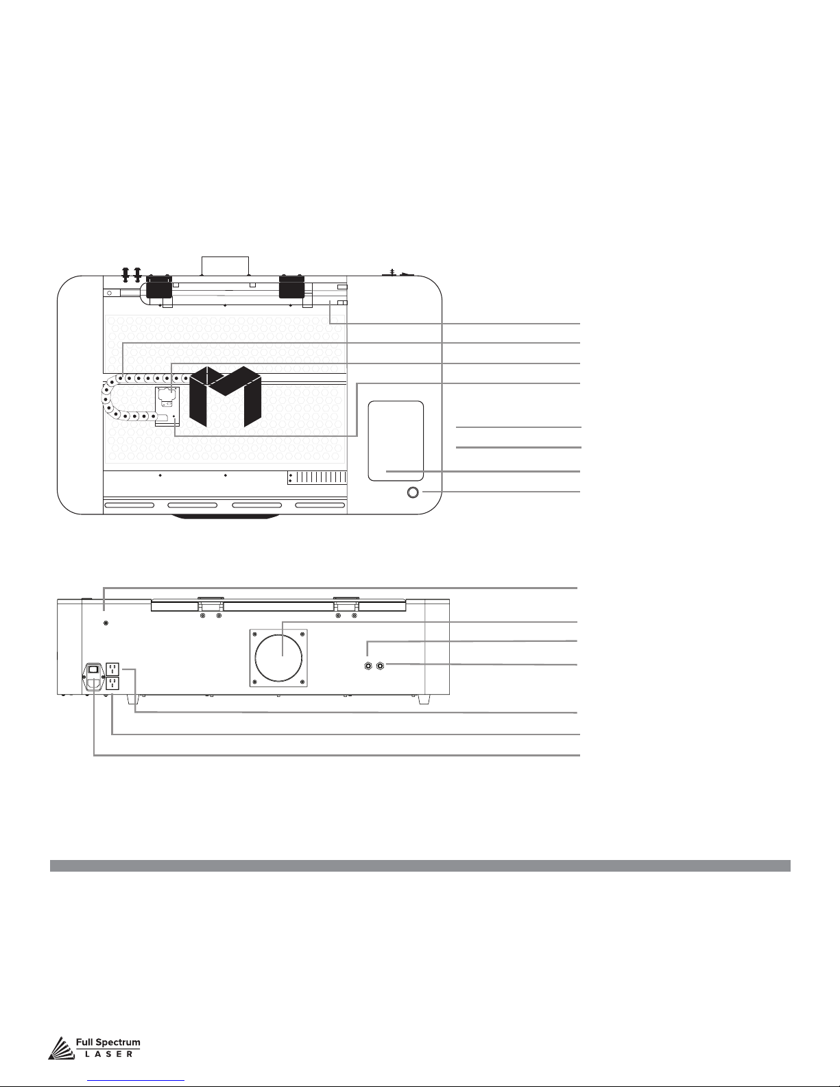
45 Watt Laser Tube
X-Gantry
Focus Head
Wide Angle Camera
Ethernet Port
USB Port
Touchscreen
Pause/ Stop Button
Air Inlet
Exhaust Flange
Water Inlet
Water Outlet
Air Compressor Power Outlet
Exhaust Fan Power Outlet
Power Switch
Compliance Statement The Full Spectrum Laser MUSE Laser System is a class 3R laser product, as dened in International Standard IEC 608251. The
Full Spectrum Muse complies with 21 CFR 1040.10 and 1040.11, the Federal Performance Standards for LightEmitting Products, except for deviations
pursuant to Laser Notice No. 50, dated July 16, 2001. The Center for Devices and Radiological Health of the US FDA issued Laser Notice No. 50 to
permit manufacturers to classify and manufacture their products in accordance with the International Standard. 21 CFR 1040 and IEC 608251 require that
certication, identication and warning labels be placed on laser products. Reproductions of the labels found on the Full Spectrum Hobby Advanced Laser
System follow, with locations specied:
Technical Support is available from 8am to 5pm (PST) M - F at [email protected].
3
Page 5

SECTION I. SAFETY FIRST
Familiarize yourself with these icons. They indicate areas that require special attention.
Pro Tips:
Watch for this icon to receive
valuable advice in getting the
most from your machine.
CO2 Gas Icon:
Warns of potential gas leaks
and associated hazards.
Shock Icon:
Warns of potential
electrical hazards.
Level Icon:
Indicates the need
for a level surface.
Fragile Icon:
Warns of fragile parts or
materials, such as glass.
Safe Disposal Icon:
Calls attention to proper
disposal of waste materials.
Laceration Icon:
Warns of potential sharp
edges that could cause
cuts or injury.
Temperature Icon:
Warns of potential temperature
issues with your machine.
Technical Support is available from 8am to 5pm (PST) M - F at [email protected].
Fire Icon:
Warns of potential
re hazards.
Caution Icon:
Warns of important area
of caution not covered by
other icons.
Laser Icon:
Warns of potential dangers
associated with laser usage.
Attention Icon:
Calls attention to an
important point.
4
Page 6

General Safety
Read and be familiar with all safety protocols and procedures before operating any machinery. It is the
responsibility of the operator to ensure all safety precautions are correctly followed and the machine is
properly assembled and in working order.
ALWAYS inspect the laser cutter for damage or breakage before each use. Do not
operate machinery that is damaged or defective in any way.
ALWAYS have a clean, level, and open work space to unbox and place your laser cutter
ALWAYS be aware that the laser tube is made of glass and is therefore extremely
fragile and can cause severe lacerations if broken.
ALWAYS be aware that the laser tube is lled with CO2 gas. While carbon dioxide is a
class 2.2 gas (nonammable and nontoxic), release of this gas from the laser tube will
render your laser inoperable.
NEVER modify, disassemble, or in any way alter the construction of the laser and never
start up a system that has been modied or disassembled.
NEVER leave the laser system unattended during operation.
KEEP YOUR LASER SYSTEM CLEAN – A build up of cutting and engraving
residue and debris is dangerous and can create a re hazard. Keep your laser system
clean and free of debris. Regularly remove the cutting grid to clean any small pieces
that have gotten stuck or fallen through.
DO NOT disassemble the machine or remove any of its protective covers.
NEVER place hands or ngers into moving parts such as cooling fans.
Technical Support is available from 8am to 5pm (PST) M - F at [email protected].
5
Page 7

Laser Safety
The output of the CO2 engraving laser is fully contained in a Class 1 enclosure during normal
operation. The laser cabinet has a safety interlock switch that deactivates the laser if the door is
opened during operation, and no special precautions are necessary to operate the high power
laser safely. However, the output beam of the Alignment Laser (visible red diode laser) is accessible
to the operator during normal operation, giving the total system an overall rating of Class 3R.
Class 3R lasers have minimal safety concerns when used properly and handled with care.
Follow these safety guideline at all times:
NEVER
portion of the cabinet will expose the laser system and greatly increase the risk of injury and/or
re. Personal injury and re risks are especially pronounced if the machine is operated with the
bottom panel removed. Remember that the CO2 laser beam is invisible!
operate the machine with any of the panels removed. Be aware that removal of any
NEVER engrave or cut any material containing PVC or vinyl. These materials (along with other
chlorine/ chloride containing materials) produce a corrosive vapor that is extremely harmful to
humans and will destroy your machine. Your warranty will be void if your machine is damaged
by corrosion from engraving or cutting PVC or vinyl.
NEVER engrave or cut any unknown material. The vaporization/melting of many materials,
including but not limited to PVC and polycarbonates, can give off hazardous fumes. Please refer
to the MSDS sheet from the material manufacturer to determine the response of any work
material to extreme heat (burning/re hazard).
ALWAYS use the air assist, especially while vector cutting. Vector cutting movements are
relatively slow and apply an extremely large amount of heat to the workplace. This buildup of
heat can create a signicant re risk.
NEVER run laser with lid open. Always be sure the lid is closed and never tamper with lid
safety mechanism.
NEVER operate the machine without a properly operating ventilation system. Most materials
produce an irritating smoke when engraved. Some materials, including but not limited to: paint,
varnish, composition board, and plastics, produce compounds that can be harmful if concentrated.
NEVER look into the beam of the Alignment Laser (visible red diode laser).
NEVER aim any laser towards an aircraft or vehicle that is in motion. The bright light can
ashblind,cause glare, or distract the pilot or driver.
Technical Support is available from 8am to 5pm (PST) M - F at [email protected].
6
Page 8

Laser Safety (Cont.)
The standard reference for laser safety is the American Standard for the Safe Use of Lasers,
Z136.12000, developed by the American National Standards Institute (ANSI). This reference is
the basis for many of the federal regulations for laser and laser system manufacturers, and for the
Occupational Safety and Health Administration (OSHA) laser safety guidelines. It contains detailed
information concerning proper installation and use of laser systems. While the ANSI standard itself
does not have the force of law, its recommendations, including warning signage, training, and the
designation of a laser safety ofcer, may be compulsory under local workplace regulations when
operating laser systems above Class I. It is the operator’s responsibility to ensure that the installation
and operation of the Full Spectrum Laser Hobby Laser System is performed in accordance with all
applicable laws. Copies of ANSI Standard Z136.12000 are available from: LASER INSTITUTE OF
AMERICA 12424 RESEARCH PARKWAY, SUITE 125 ORLANDO, FL 32826 (407) 3801553.
Technical Support is available from 8am to 5pm (PST) M - F at [email protected].
7
Page 9

Fire Safety
Laser cutting and engraving systems can present a signicant re hazard due to the extremely
high temperatures generated by the laser beam. While the objective of most cutting and engraving
operations is to vaporize material without burning, most materials capable of being cut or engraved
are inherently combustible and can ignite. Usually this is a small ame of burning material issuing
from the cut zone which self extinguishes due to the air assist or depowering of the beam. However,
it is possible for the ame to propagate and set re to the machine and its surroundings.
ALWAYS keep a properly maintained and inspected 5lb or larger re extinguisher on hand.
Full Spectrum Laser recommends a Halogen re extinguisher or a multipurpose dry chemical re
extinguisher. Halogen extinguishers are more expensive than a dry chemical, but offer certain
advantages should you ever need to use an extinguisher. The Halogen extinguisher discharges a
clean, easily removable substance that is not harmful to the mechanics or wiring of the laser system.
The dry chemical extinguisher discharges a sticky, corrosive powder that is very difcult to clean up.
BE AWARE that stacking materials (especially organic materials such as paper) can lead to
increased risk of ame propagation or work piece ignition.
NEVER operate your machine unattended. There is a signicant risk of re if the machine is set
improperly, or if the machine should experience a mechanical or electrical failure while operating.
ALWAYS keep the area around the machine clean and free of clutter, combustible materials,
explosives, or volatile solvents such as acetone, alcohol, or gasoline.
ALWAYS use air assist when vector cutting.
BE CAREFUL when vector cutting. Many materials have the potential to burst suddenly into
ames – even materials that may be very familiar to the user. Always monitor the machine when
it is operating.
PRO TIP! Experience shows that vector cutting with the laser
has the most potential to create an open ame. Acrylic in all
its different forms has been shown to be especially ammable
when vector cutting with a laser.
Technical Support is available from 8am to 5pm (PST) M - F at [email protected].
8
Page 10

Fire Safety (Cont.)
NEVER CUT PVC (polyvinyl chloride) under any circumstances: fumes are highly toxic
and potentially lethal.
NEVER store any ammable materials in the inside of the device or in the immediate vicinity of
the device. Debris and leftover produced materials within the machine must to be removed to prevent
re hazard.
ALWAYS have on hand a rst-aid kit designed for the initial treatment of burns and smoke
inhalation. Be sure to store this kit in an area that is outside risk areas.
Woodshop Dust Fire Safety Considerations*
Before processing materials the user must verify whether harmful materials can be generated
and whether the lter equipment of the exhaust system is suitable for the harmful materials. We
emphasize that it is the responsibility of the user to consider the national and regional threshold
values for dust, fogs and gases when selecting the lters and the exhaust system.
(The values for the maximum workplace concentration must not be exceeded.)
Be mindful of large quantities of fuel in the form of wood and wood products, sawdust, and
ammable materials such as paints, oil nishes, adhesives, solvents, and liquid propane for
internal combustion engines.
Preventing the buildup of dust is one of the key means for controlling re and explosion hazards.
The principal engineering control technology for control of dust is exhaust ventilation. The primary
work practice control is good housekeeping.
Dust collection is best accomplished at the source-at the point of operation of the equipment, if
feasible. For many pieces of equipment, well-designed ducts and vacuum hoods can collect most
of the dust generated before it even reaches the operator.
Very ne dust that manages to escape point-of-source collection can be captured from above by
general exhaust points located along the ceiling. These control technologies are effective for most
equipment, excepting machines that commonly produce the very nest dust or large quantities of dust.
*These guidelines come from the U.S. Department of Labor
Technical Support is available from 8am to 5pm (PST) M - F at [email protected].
9
Page 11

Electrical Safety
The power supply is capable of outputting DC 20,000V at up to 20mA. This power is also provided to
the discharge terminals on the laser tube itself. Your laser shipped with silicone terminal covers that
prevent access to bare wiring—notify Full Spectrum Laser support and immediately cease operations
if these covers ever slip and expose bare wire.
DO NOT open any of the machine’s access panels while the unit is plugged in. Opening a panel
may expose the operator to the unit’s AC input power. The AC input power is potentially lethal and is
located on the far right within the cabinet.
NEVER make or break any electrical connections to the system while the unit is turned on.
NEVER access the electronics area with hands or tools unless the unit is disconnected from power
for at least one hour.
NEVER replace the installed 10 amp fuse with a fuse of a higher rating. This will void your warranty
and the electronics will not be adequately protected from surges or short circuits.
POWER ON/OFF is controlled by the switch at the back of the machine. To power the machine on,
press the (-) side down. To turn power off, press the “o” side down.
IN CASE OF A BLOWN FUSE always contact Technical Support before replacing any fuses.
Technical Support is available from 8am to 5pm (PST) M - F at [email protected].
10
Page 12

SECTION II. UNBOXING YOUR MUSE
When your Muse arrives, it will require careful unboxing and examination of parts. Follow these
instructions for best results. Note that if you purchased a Coolbox with your muse, you will be directed
to Appendix A: Coolbox Assembly for unpacking instructions
FRAGILE PARTS! Be gentle in removing the foam packaging and
accessories. Never pull or force the packaging loose from the laser
cutter. Be particularly aware that the water inlet and outlet nodes
protrude from the tube and are extremely fragile when unboxing
your laser tube.
Unboxing Steps
Now that your Muse has arrived, it will require careful unboxing and examination of parts. You will
need two able-bodied adults to lift and place the machine.
Follow these instructions for best results:
1. Prepare Work Space:
solid table with adequate room for the machine is recommended (the machine’s dimensions are 32”
x 20” x 8.75”). Be sure the table is free of clutter and can support a minimum of 100 lbs (the machine
weighs 70 lbs on its own).
You will need an open, level work space to place your laser cutter. A
2. Place Box: Set the box on a at space near where you will place the machine (such as the
oor). Open the box carefully from the top. If you use a cutting tool to open the box, be careful not to
allow the cutting edge to cut past the cardboard box. Always use all tools with caution and only as
specied by the manufacturer.
3. Remove Packaging: Gently remove the following from the box: the honeycomb plate, the
Quick Start Guide and the top (4) foam pieces securing the machine.
4. Remove Accessories: Nestled in packing foam, inside the interior of the machine, are the
following parts and accessories: a plastic bag with cords and small accessories, the water pump
and the air compressor. Inspect these parts to insure they are accounted for and intact.
5. Place Muse: This will require two adults as the machine weighs approximately 70 lbs. Standing
on both ends, grip the machine from the bottom and gently lift the machine out of the box, leaving the
bottom foam still inside the box. Place on the clean, at table you plan on keeping it. Your Muse is
now unboxed.
6. Inspect your Muse: If have any questions, contact your sales representative or
customer support. Refer to your Muse Quick Start Guide or download the Muse User Manual for
assembly instructions.
Technical Support is available from 8am to 5pm (PST) M - F at [email protected].
11
Page 13
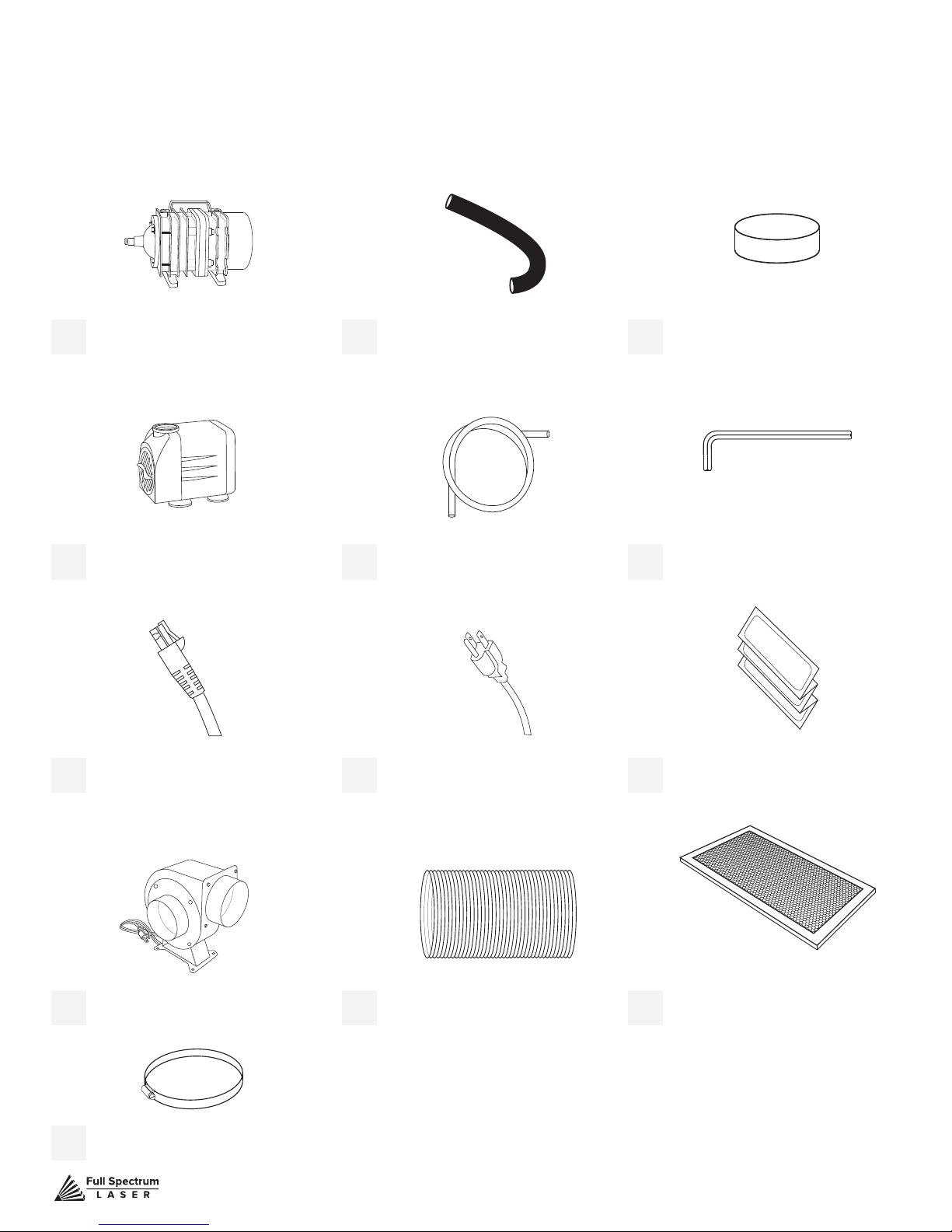
Unpacking List
Air Hose
Air Compressor
Air Compressor
Your laser shipped with the following included parts and accessories:
(1) Air Assist Tube(1) Air Compressor
(1) Water Pump (2) Water Tubes
(1) Power Cord(1) Ethernet Cable
(1) Focus Billet
(1) 2.5mm Hex Key
(1) Thermal Paper
(2) 4’ Ducting Clamps
Technical Support is available from 8am to 5pm (PST) M - F at [email protected].
(1) 10’ Ducting(1) Exhaust Fan
(1) Honeycomb Tray
12
Page 14
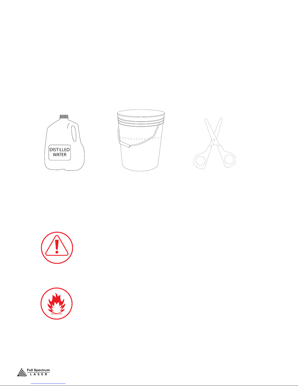
Additional Requirements
In addition, you will need the following tools and accessories
(not included with your machine purchase):
• 3-5 gallons of distilled water
• A ve gallon bucket
• Small Scissors
Water BucketDistilled Water Small Scissors
CAUTION!
working exhaust. Full Spectrum recommends exhaust systems
capable of 232 CFM. Keep in mind that exhaust systems with
high ow rates may require xtures for thin materials.
You should never operate your laser without a
FIRE WARNING! It is important that either rigid or exible metal
ducting be used in the exhaust system. Any type of “soft” ducting
is potentially ammable and should not be used under
any circumstance.
Technical Support is available from 8am to 5pm (PST) M - F at [email protected].
13
Page 15
SECTION III. INSTALLATION & ASSEMBLY
With your laser cutter unboxed and placed in its permanent work space we can now prepare it for
use. This is a simple process that should take less than half an hour to complete. Note that if you
purchased a Coolbox with your Muse, Step 2: Connect the Exhaust System; Step 3: Assemble the
Water System; and Step 3: Assemble the Air Compressor will be replaced with the instructions in
Appendix A: Coolbox Assembly.
Assembly Stages:
1. Locate & Remove Zip Ties
2. Connect the Exhaust System
3. Assemble the Water System
4. Assemble the Air Compressor
5. Connect Electrical Power
6. Connect the Ethernet Cable
7. Connect to RetinaEngrave 3.0 Software
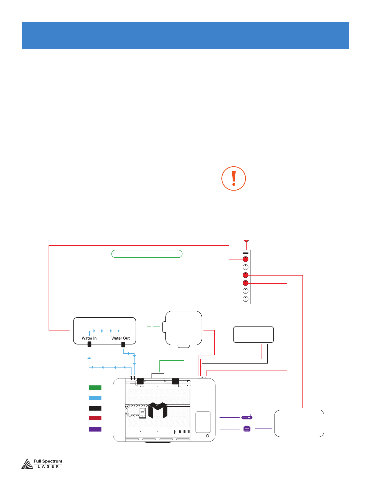
Window/ Exhaust Port
Cooling System
Exhaust
System
This conguration does not in-
clude Coolbox. If you are using
a Coolbox system with your
Muse, refer to Appendix A:
Coolbox Assembly.
Wall Outlet 110 V
Power Strip
Air
Compressor
Water Out
Ducting
Water Tubing
Air Tubing
Power Cords
Software Connection
Figure 3.1
Technical Support is available from 8am to 5pm (PST) M - F at [email protected].
Water In
Options
Computer
14
Page 16
Assembly Stage 1: Locate & Remove Zip Ties
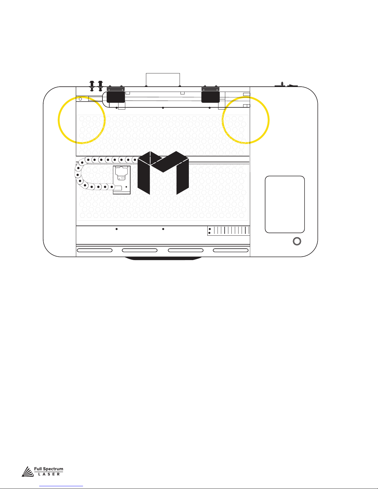
To secure the machine during shipping, yellow zip ties are used to hold the laser head assembly and the
x-gantry. These zip ties must be removed before operating your laser cutter for the rst time.
Figure 3.2
1. Locate Yellow Zip Ties: Yellow zip ties secures the laser head and x-gantry during shipping.
Open the lid and identify all yellow zip ties.
2. Cut and Remove Yellow Zip Ties: Using a small pair of scissors (nail cutters work remarkably
well), carefully cut and remove ALL yellow zip ties. DO NOT cut any other cord or wire. Be aware that the
glass laser tube is extremely fragile. Be careful NOT to damage any part of the machine during this process.
Technical Support is available from 8am to 5pm (PST) M - F at [email protected].
15
Page 17
Assembly Stage 2: Connect the Exhaust System
It is required that an exhaust fan is connected and operating whenever you run a job on your laser.
A properly installed exhaust fan removes smoke and fumes from the case and exhausts them to the
outside of the building or a fume extractor. For Coolbox users, skip this step and refer to Appendix A:
Coolbox Assembly.
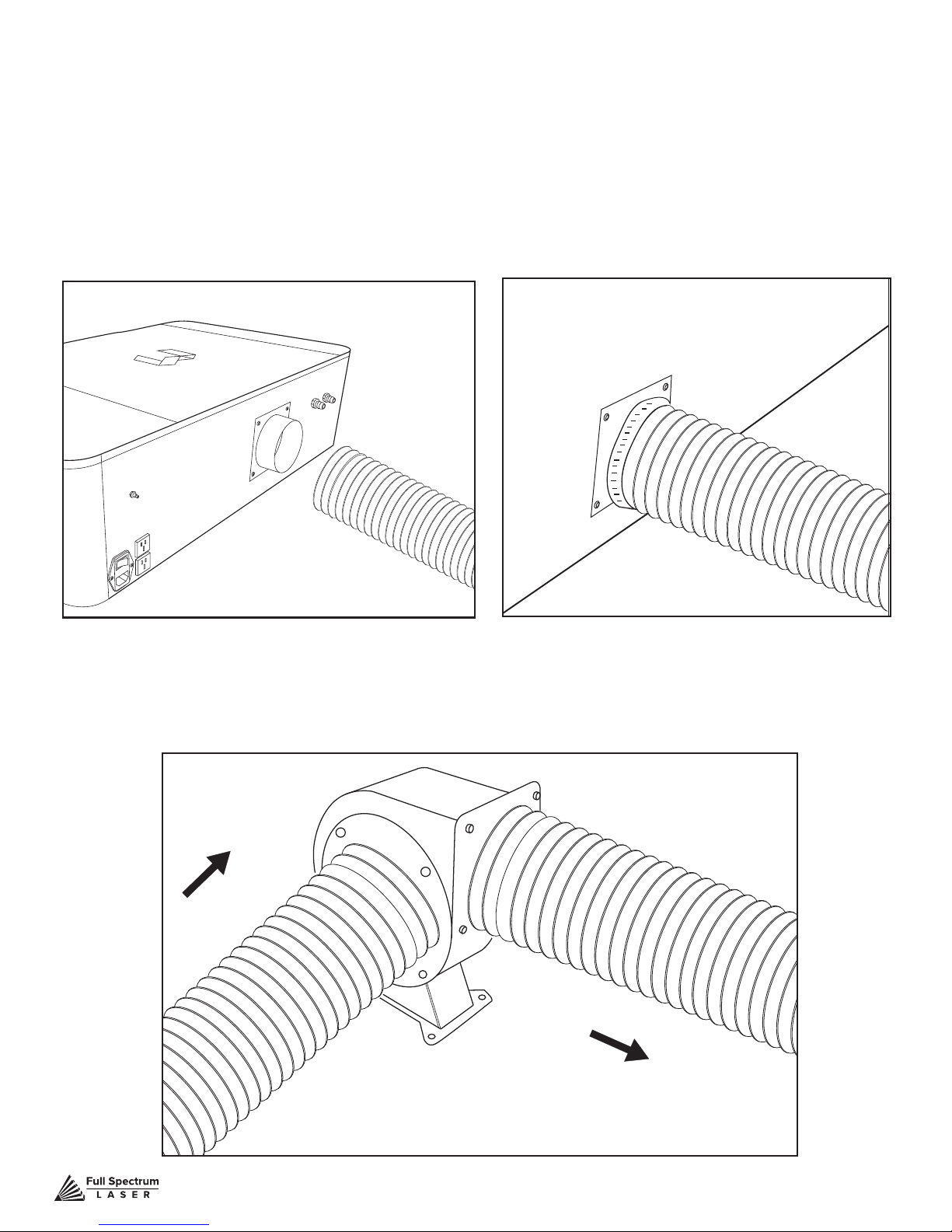
1. Position Ducting: Place your 4” ducting over the Exhaust Port located at the back of the
machine and hold. Secure with 4” ducting clamp.
2. Attach Exhaust Fan: Secure the other end of the ducting, connected to the machine, to the
exhaust fan. Now repeat the ducting and clamping process on the other side of the exhaust fan,
creating a sequence of machine to ducting to exhaust fan to second ducting. Now plug in the exhaust
fan into the bottom power plug marked “exhaust” on the back of your Muse machine.
FROM MUSE
TO OUTSIDE WINDOW
Figure 3.3 Figure 3.5Figure 3.4
Technical Support is available from 8am to 5pm (PST) M - F at [email protected].
16
Page 18
3. Ventilate Outside: Set the open end outside of a window or an installed ventilation outlet.
Check your system for leaks—most can be remedied with duct tape. Please be aware that the
protective housing is not designed to be airtight; the front grill is designed to allow an exhaust
system to draw fresh air through the work area.
4. Connect to Power: Plug the exhaust fan power cord into the lower power plug marked
“exhaust fan” on the back of your Muse. Note that accessories plugged into the back of your Muse will
only turn on when the laser is red (as intended to save power).
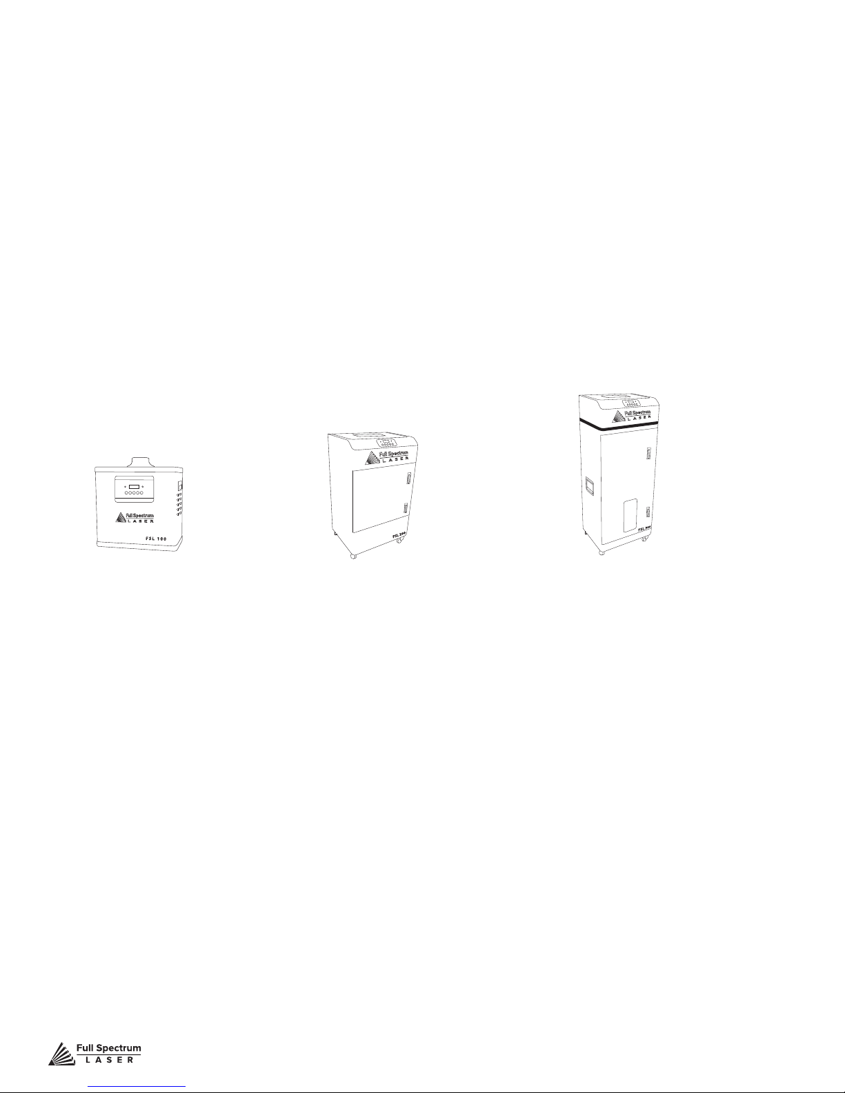
5. Fume Extractor Upgrade (optional): You can also upgrade to a fume extractor. Fume
extractors are air purifers that clean the air through HEPA Filters. Fume extractors do not require
outside ventilation. This is a great option for workshops that do not have the option to ventilate
outside. Both the extractors and the ters are available on the Full Spectrum Laser website at
https://www.fslaser.com/Products/LaserAccessories. Ask a customer support representative which
fume extractor is right for your needs.
Small Fume Extractor
Fume Extractor lters require routine cleaning and replacement, dependent on use and materials cut.
Generally, fume extractor suction will diminish and odors will be detected as lters clog.
Medium Fume Extractor
Large Fume Extractor
NEVER use a fume extractor without all lters in place.
Follow these maintenance guidelines:
Pre-Filters
Clean often. Use a shop vacuum to clean as debris builds. Check weekly, especially if cutting a lot of
wood. When accumulated debris remains over 70% after cleaning, replace Pre-Filter.
HEPA Filters
Clean immediately when suction is reduced. Use a shop vacuum to clean accumulated dust. When
cleaning does not return optimal suction power, replace HEPA Filter.
Activated Carbon Filters
Clean when odors are detected or suction is reduced. Gently shake excess dust and debris from
carbon lter and follow with a shop vacuum. When cleaning no longer eliminates detectable odors,
replace Activated Carbon Filters.
https://www.fslaser.com/Products/LaserAccessories.
Technical Support is available from 8am to 5pm (PST) M - F at [email protected].
17
Page 19
Assembly Stage 3: Assemble the Water System
Muse uses a water-cooled continuous beam CO2 laser tube. The tube requires a ow of room
temperature water to regulate the temperature of the laser tube. Your purchase includes
a water pump for cooling the laser tube. For Coolbox users, skip this step and refer to Appendix A:
Coolbox Assembly. Coolbox users will not need a bucket.
Never Fire the Laser: Without a correctly connected and
powered water pump. Firing the laser without turning the pump
on or, worse, with no water in the system,will severely degrade
or destroy your laser tube and void your warranty.
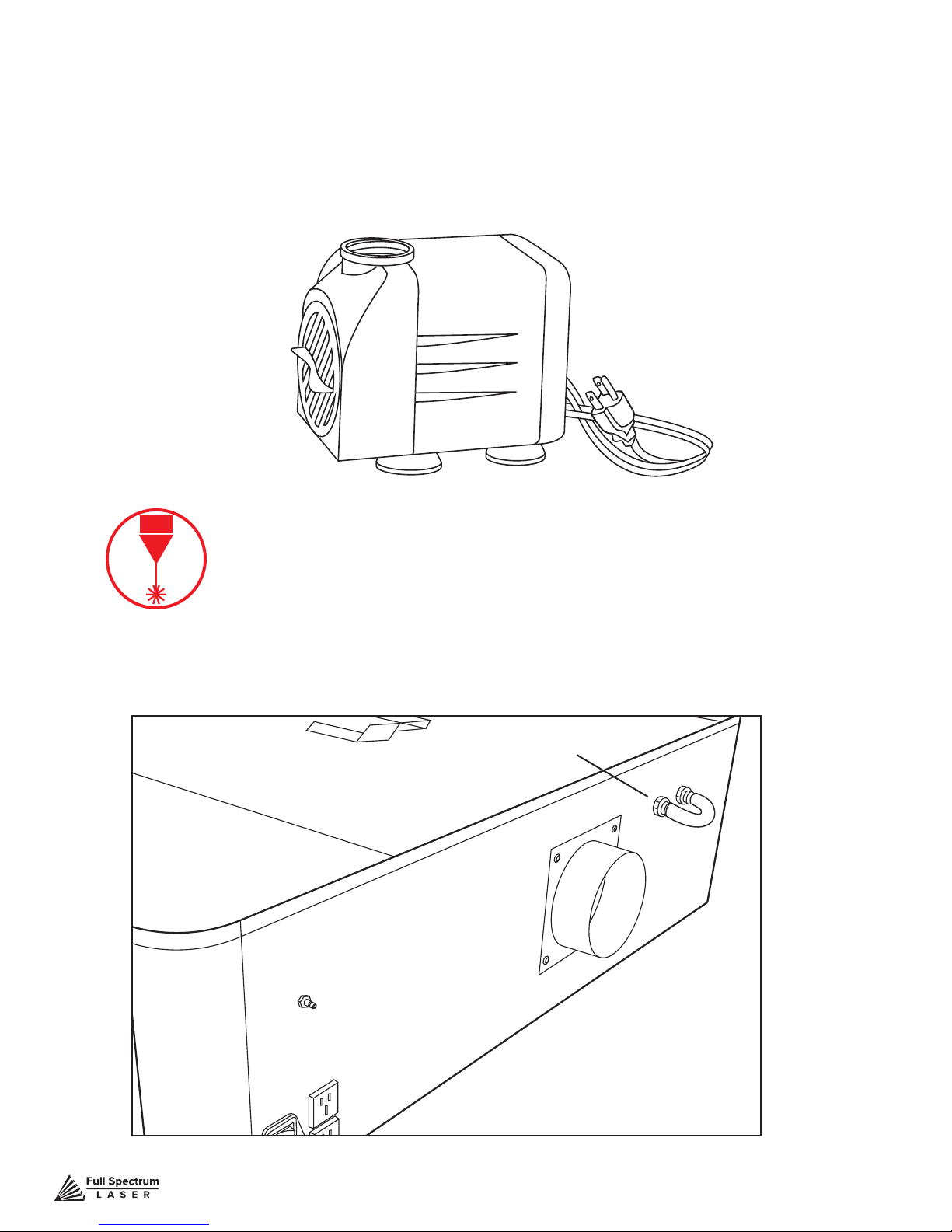
1. Remove Capping On Water Inlet /Outlet: Remove the short silicone tubing, capping
the water inlet and outlet on the back of the machine.
Tubing Capping
Technical Support is available from 8am to 5pm (PST) M - F at [email protected].
Figure 3.6
18
Page 20
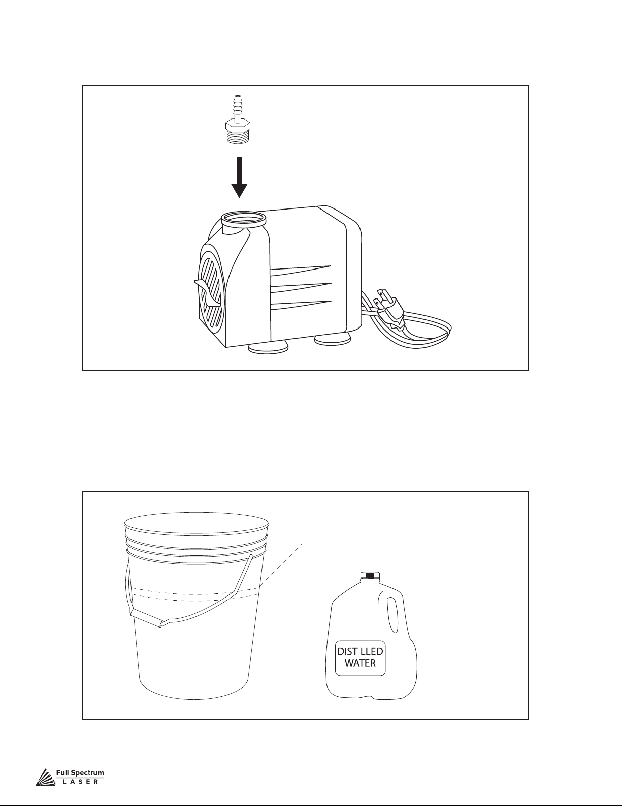
2. Attach Water Pump Fitting: Remove the water pump from its packaging. Attach the
plastic tting to the water pump by gently screwing it on.
Figure 3.7
3. Prep Water Bucket: Fill a clean 5 gallon bucket (not included) with 3 - 4 gallons of distilled
water (not included). ALWAYS use only distilled water and replace often. It is recommended that you
choose a bucket with a lid and cut holes to allow the tubes to t. This will prevent debris falling into
your water bucket.
Water Line
Figure 3.8
Technical Support is available from 8am to 5pm (PST) M - F at [email protected].
19
Page 21
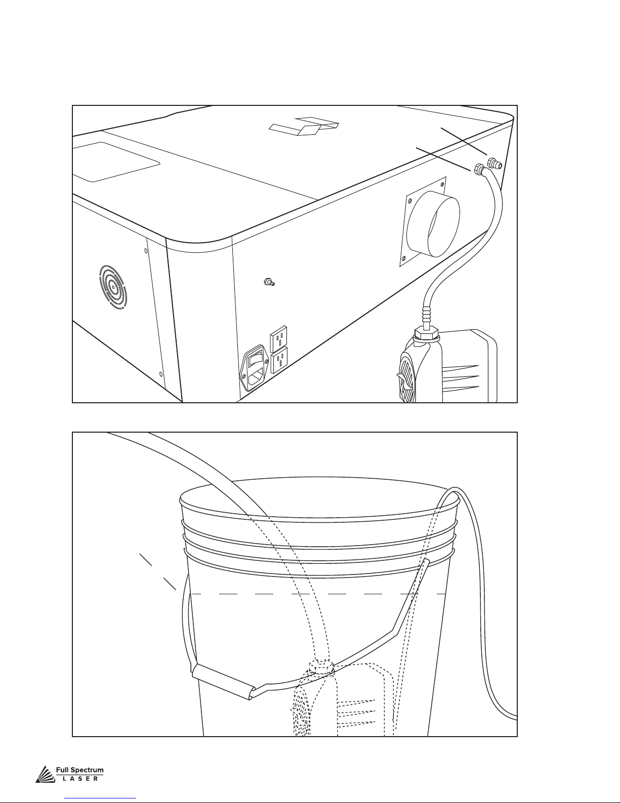
4. Attach Inlet Water Tubing: Push one end of one of the two (2) silicone water tubes onto the
water pump tting. Now attach the other end of that tubing to the “water inlet” located at the back of
machine. Completely submerge the assembled water pump in the bucket of distilled water.
Water Out
Water In
Figure 3.9
Water Line
Figure 3.10
Technical Support is available from 8am to 5pm (PST) M - F at [email protected].
20
Page 22
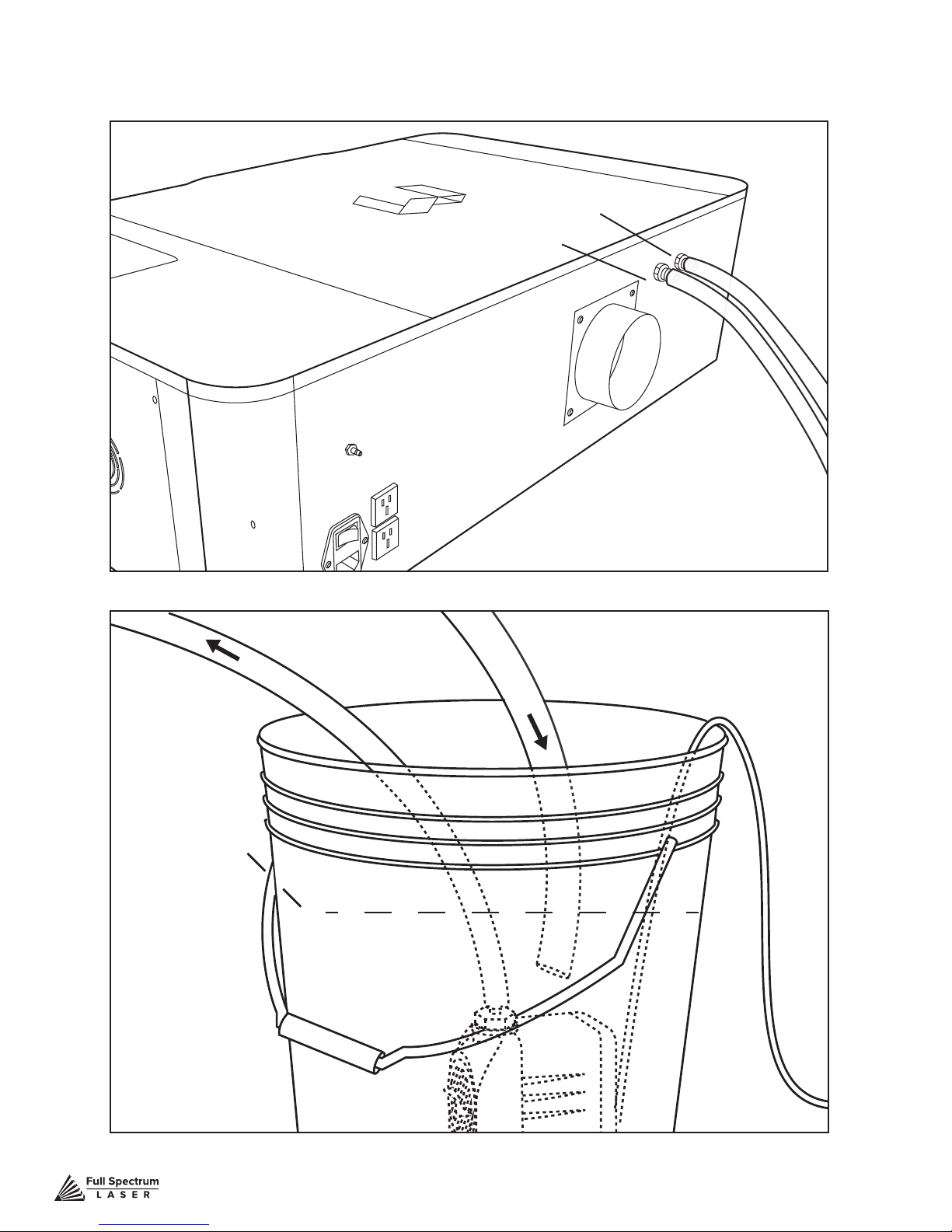
5. Attach Outlet Water Tubing: Push one end of the other silicone water tubing onto the
W
“water outlet”. Place the other end of the water tubing into bucket of distilled water.
Water Out
Water In
Figure 3.11
W
a
t
e
r
a
t
e
r
I
n
o
u
t
Figure 3.12
Technical Support is available from 8am to 5pm (PST) M - F at [email protected].
21
Page 23
Assembly Stage 4: Assemble the Air Compressor
Air is used as a pressurized gas to assist in cutting and engraving operations. This pressurized
air is critical to safe and efcient cutting operations as it not only helps cut through material more
quickly, but also helps prevent the formation of ames. For Coolbox users, skip this step and refer to
Appendix A: Coolbox Assembly.
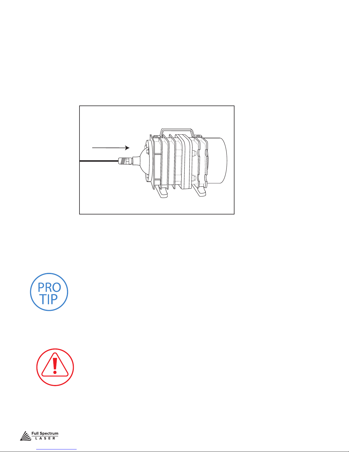
1. Attach Push Fitting: Remove the air compressor from its packaging. Gently attach the air hose
push tting to air compressor.
Figure 3.13
2. Attach Air Hose to Air Compressor: Push one end of the black air inlet hose into the air
compressor push tting until it is snug.
PRO TIP! We recommend that you attach the laser and water
pump to a power strip and use that to control the mains power
to the unit - this ensures that the water pump is always on when
the laser is powered.
CAUTION! Make sure that there are no air bubbles inside
of the water jacket of the laser tube. Air bubbles can create
local hot spots in the lasing chamber and reduce the lifetime
of your tube. If present, water bubbles typically migrate
to the electrodes on either end of the tube. You should
visually inspect the laser tube to make sure that bubbles are
not present; slightly tilting the laser while powering on the
circulation pump is usually sufcient to remove bubbles.
Technical Support is available from 8am to 5pm (PST) M - F at [email protected].
22
Page 24
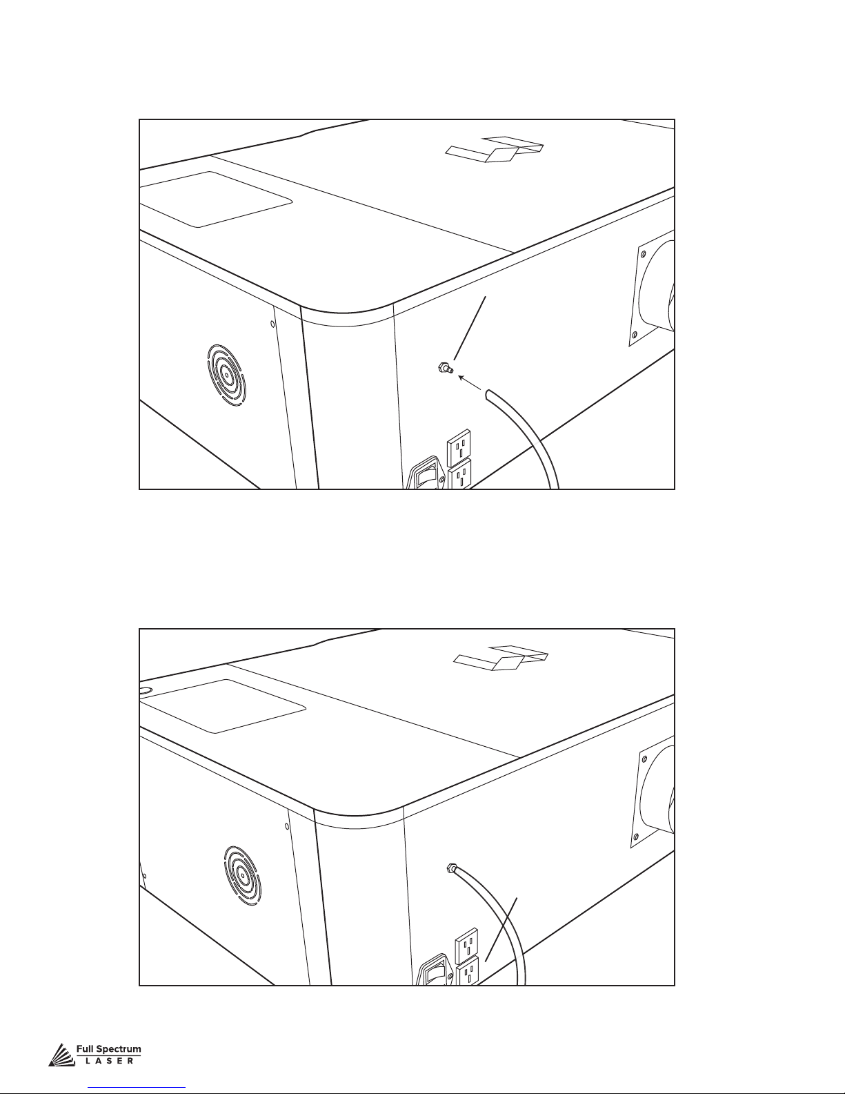
3. Attach Air Hose to Laser Cutter: Insert the other end of the black air inlet hose into the “air
inlet” nozzle in the back of laser cutter via the barbed air connect tting.
Air Inlet
Figure 3.14
4. Connect to Power: Plug the air compressor into the upper power plug marked
“air compressor” on the back of your Muse. Note that air compressor will only turn on when the
laser is ring.
Air Compressor
Power Outlet
Figure 3.15
Technical Support is available from 8am to 5pm (PST) M - F at [email protected].
23
Page 25
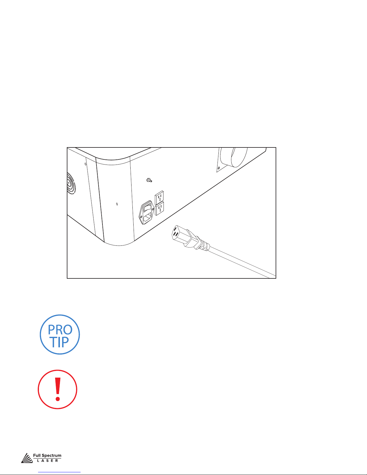
Assembly Stage 5: Connect Electrical Power
Muse’s Laser System, and available accessories, are congured to accept 110VAC at 60Hz. 220VAC
units connect to power through an included converter (single-phase 220VAC).
1. Prepare Power Cord: Remove the electrical cord from its packaging.
2. Plug in Power Cord To Laser Cutter: The power cord plugs into a “C14” power receptacle
located on the right side of the machine.
3. Plug in Power Cord to Outlet: Plug the power cord into any proper outlet socket
in your workspace.
Figure 3.16
PRO TIP! Please be aware that the accessories will increase the circuit
load; the most signicant power draw usually comes from the blower/
exhaust system. Consult the manufacturer’s information and manual for
the operating parameters of your exhaust system.
IN CASE OF A BLOWN FUSE: The laser system is equipped with
a fuse on the power inlet to protect the machine from surges or short
circuits. If this fuse ever needs replacement, please contact Full
Spectrum Laser technical support.
Technical Support is available from 8am to 5pm (PST) M - F at [email protected].
24
Page 26
Assembly Stage 6: Connect the Ethernet Cable
Muse software is browser-based, which means there is nothing to download. With any Mac or
PC, you only need an internet browser (such as Google Chrome) to access the latest version of
RetinaEngrave 2.0. The easiest method is to connect the Ethernet cable that came with your Muse.
1. Identify the Ethernet Cable: Locate and remove the included Ethernet cable
from its packaging.
2. Plug Ethernet Cable into Laser Cutter: Plug in the Ethernet cable into the Ethernet
slot on the Muse.
3. Plug Ethernet Cable into Computer: Plug the other end of the Ethernet cable into your
computer’s Ethernet slot.
4. Connect Via Router (Recommended): Router connectivity is more reliable than
directly connecting via Ethernet and should be the primary way of connecting. Direct connect from
laser to computer should be a secondary choice, if possible. If direct connecting to router is not
available (i.e. due to location of router) then we recommend using an Ethernet to Wi-Fi adapter
that is connected to the router. If both of those are not possible then direct connection to computer
can be utilized via the Ethernet cable.
PRO TIP! Muse can connect to your computer via either Ethernet
or USB (but not both simultaneously). Full Spectrum includes an
Ethernet cable in the laser accessories and recommends the use
of Ethernet cables as USB is more prone to electrical interference.
ATTENTION! Your laser must be connected to your computer
in order to download jobs. The laser can store jobs in its onboard
memory while powered, however loss of power will cause stored
jobs to be lost. If you purchase and install a USB device, you can
download jobs to your laser and run them without a computer
attached (however you will not be able to alter the job settings
from the laser control panel). Because a USB device is not volatile
memory, jobs are stored between power cycles.
PRO TIP! If your laser is located more than 6ft from your
computer, you will need to use the Ethernet connection.
Connecting via Ethernet while the power is on requires you to
power cycle your machine in order to obtain an IP address.
Technical Support is available from 8am to 5pm (PST) M - F at [email protected].
25
Page 27

Assembly Stage 7: Connect to Software
RetinaEngrave 3.0 is a combination of a print driver and control software that communicates with,
downloads jobs to, and controls the laser system. There is no download required for RetinaEngrave
3.0. With a local connection (achievable with Wi-Fi or an Ethernet cable) your Muse software will be
available for use within your web browser
1. Turn On Laser Cutter: Turning on your laser will automatically boot up the Touch Screen
interface. Allow 30 seconds or so for the machine and touch screen to boot up.
2. Access the Application: If your network supports “Bonjour” technology (DNSSD) simply navigate to the following address to access the application: “fsl.local/”.
-OR-
3. Note the Device Address: This will be visible on lower left corner of LCD and will vary
depending on connection type (ethernet/wi).
4. Type IP Into Browser: Type this IP number into your favorite browser (Google Chrome is
recommended) and press the enter key. This will link you to the RetinaEngrave 3.0 interface.
You now have full access to the software. There is no need to install or download anything.
You must, however,keep a local connection to the device while operating the software, either
through Wi-Fi or the Ethernet cable.
Connection Methods
1. Ethernet (Preferred): Connect your Muse unit to your local router or switch using an ethernet
cable. The device IP address may be assigned automatically in most cases as supported by
your local network. In cases where no DHCP server exists, you may statically assign an IP
address from the LCD or the web application options menu.
2. Wi: Connect you Muse to a local wireless network via the LCD or web application.
3. HotSpot: Connect your PC, laptop, or tablet directly to the wireless network hosted by the unit.
4. Direct (Link-Local) Ethernet Connection: Connect an ethernet cable directly from your PC or
laptop to the device.
RetinaEngrave 3.0 Print Drivers
RE3 users can download the RE3 print drivers from the Full Spectrum Laser website in order to send
device-specic print les to the laser cutter. Go to https://fslaser.com/RetinaEngrave and choose
either the Windows print driver or the MAC/OS print driver.
Occasionally, RetinaEngrave 3.0 software will run an update. This is an
automatic process that can happen when you rst boot up the machine.
Typically updates are quick, however, there may be some occasions
where updates can take longer. You will know the machine is updating
when the interior lights of the Muse turn off. When this happens, DO
NOT turn off your machine. Allow the update to complete and the
machine lights will turn back on.
Technical Support is available from 8am to 5pm (PST) M - F at [email protected].
26
Page 28
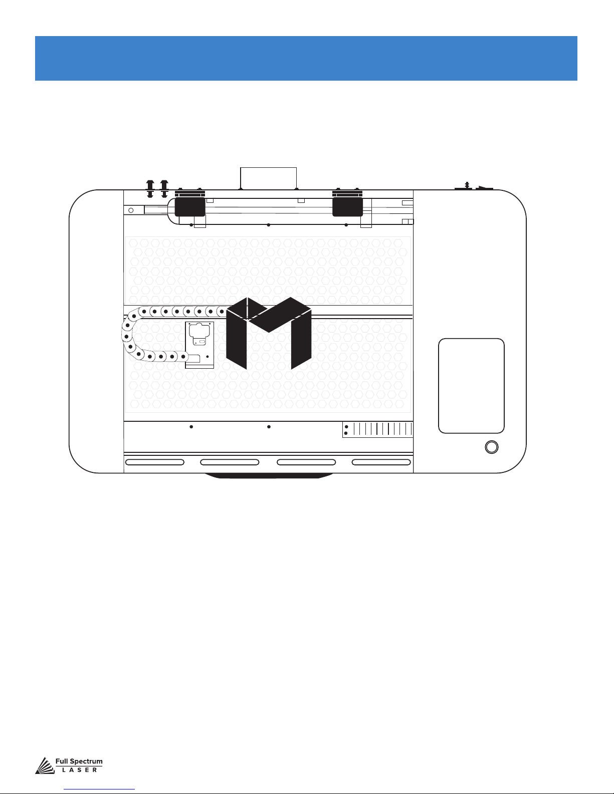
SECTION IV. TESTS & ADJUSTMENTS
It is important that your laser is tested and adjusted (if needed) for proper use before you start your
rst job. The following will be on our list of tests and adjustments:
1. Alignment Test
2. Mirror Alignment Procedure
3. Focusing
Technical Support is available from 8am to 5pm (PST) M - F at [email protected].
27
Page 29
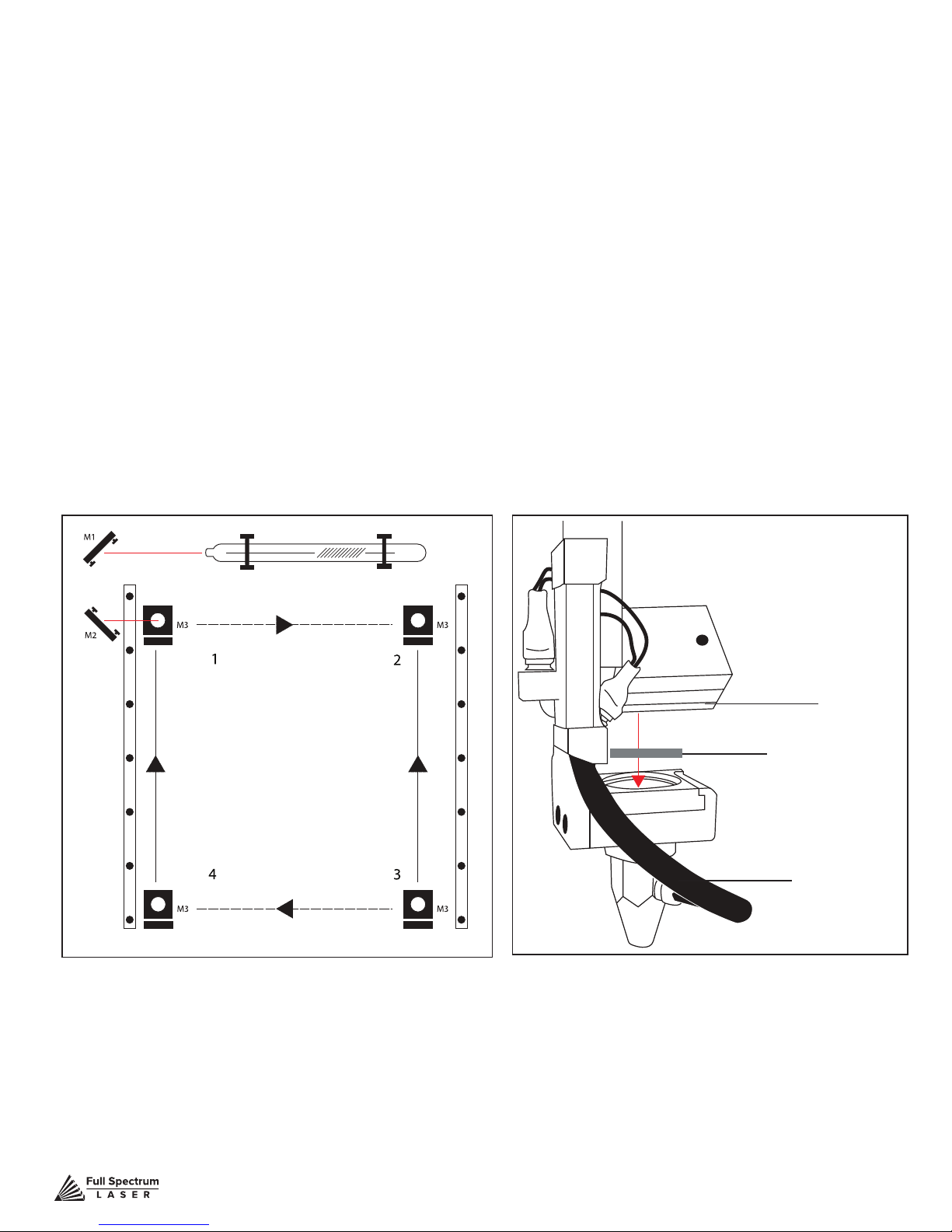
Alignment Test
The laser tube that came pre-installed in your Muse was carefully aligned in our facilities in Nevada.
When you rst turn on your machine, the mirror alignment should be perfect. It is possible, however,
that sometimes mirrors may come out alignment during shipping. Before running your rst job, you will
want to check and make sure the mirrors are properly aligned using this simple test. Once the mirror
alignment is conrmed, you are ready to use your laser cutter. If your mirrors are out of alignment, or
if you have installed a new laser tube, you must align the laser using the procedure provided. For this
alignment test we will test re the laser once in each corner of the machine to make sure the laser is
following the right path to the focus head, and ultimately to the cutting material.
1. Open the Safety Lid: You will need to access the interior of the machine.
2. Place Thermal Paper: Take a small piece of thermal paper (approx. 15 mm should be plenty)
and place it over the focus lens under Mirror #3.
3. Position Laser Head: Move the laser head into the upper left corner of the workspace.
Test Fire
Test Fire
Test Fire
Test Fire
Figure 4.1 Figure 4.2
Mirror #3
Thermal Paper
Focus Lens
Technical Support is available from 8am to 5pm (PST) M - F at [email protected].
28
Page 30
4. Close Safety Lid: Safety measures should make it impossible to re the laser with the safety
lid open. Regardless, never attempt to re the laser with safety lid open.
5. Test Fire the Laser: Press the Fire Laser Icon Button on the touch screen.
ATTENTION! Find and push this icon on your Muse touch
screen to test re the laser.
6. Repeat Test Fire in Other Three Corners: Without removing the thermal tape, repeat
ring the laser once in each of the other corners of the machine (Upper Right, Lower Right, and
Lower Left).
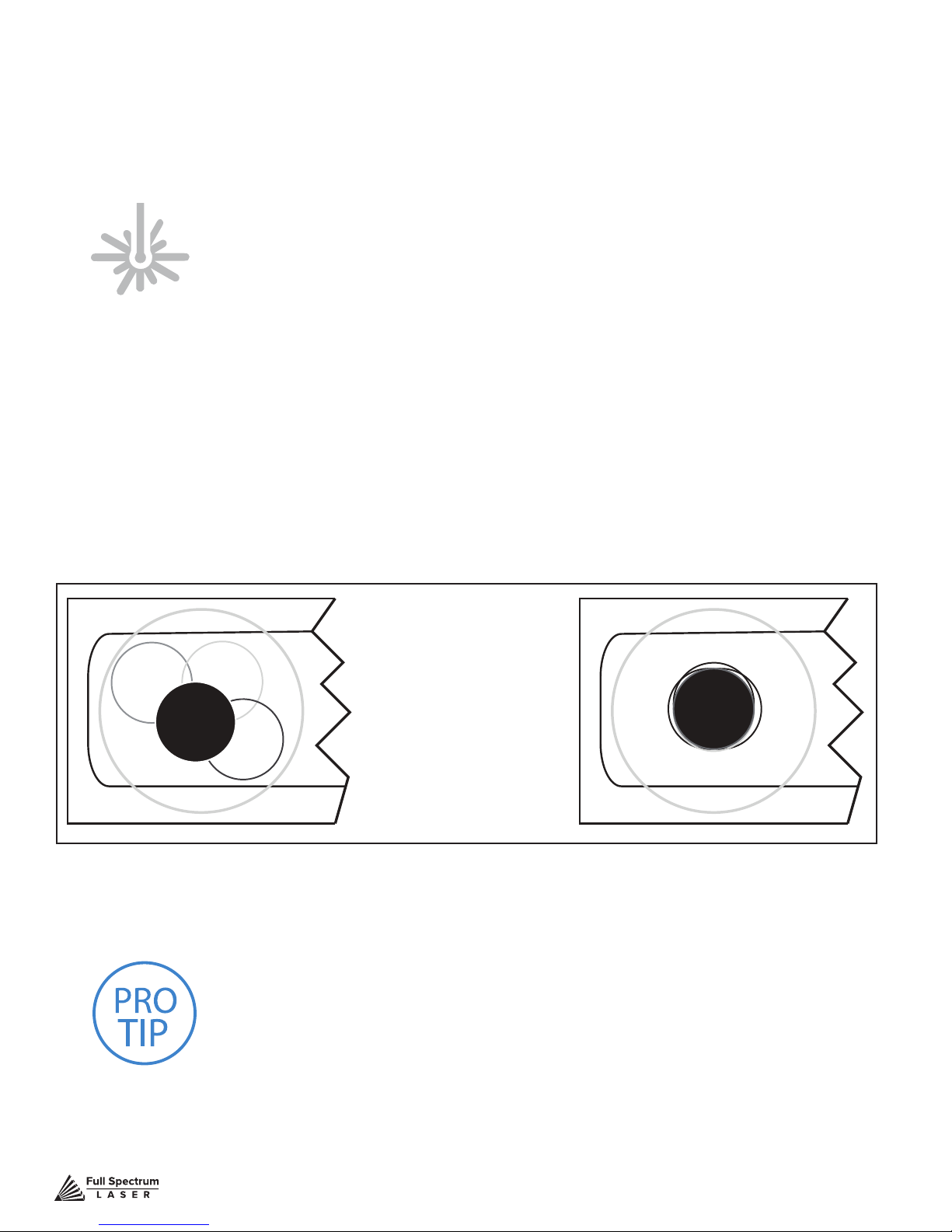
7. Check Results: With the forth corner test re complete, open the lid and remove the thermal
tape. The four burn marks should overlap each other perfectly (see illustration). If they do not overlap
perfectly, you will need to align the mirrors.
Figure 4.3
Not Aligned Aligned
PRO TIP!
will have two black dots from the test res in the top and bottom
positions. The red laser pointer is aligned with the invisible laser
pointer so gives you immediate feedback on the mirror adjustment.
By adjusting it into the middle of the two black dots, you are splitting
the error difference. Usually after 1 or 2 iterations, the black dots will
be exactly on top and this axis is aligned. The goal is to have the two
black dots overlap exactly.
The idea is that when the laser is not aligned, you
Technical Support is available from 8am to 5pm (PST) M - F at [email protected].
29
Page 31
Mirror Alignment Procedure
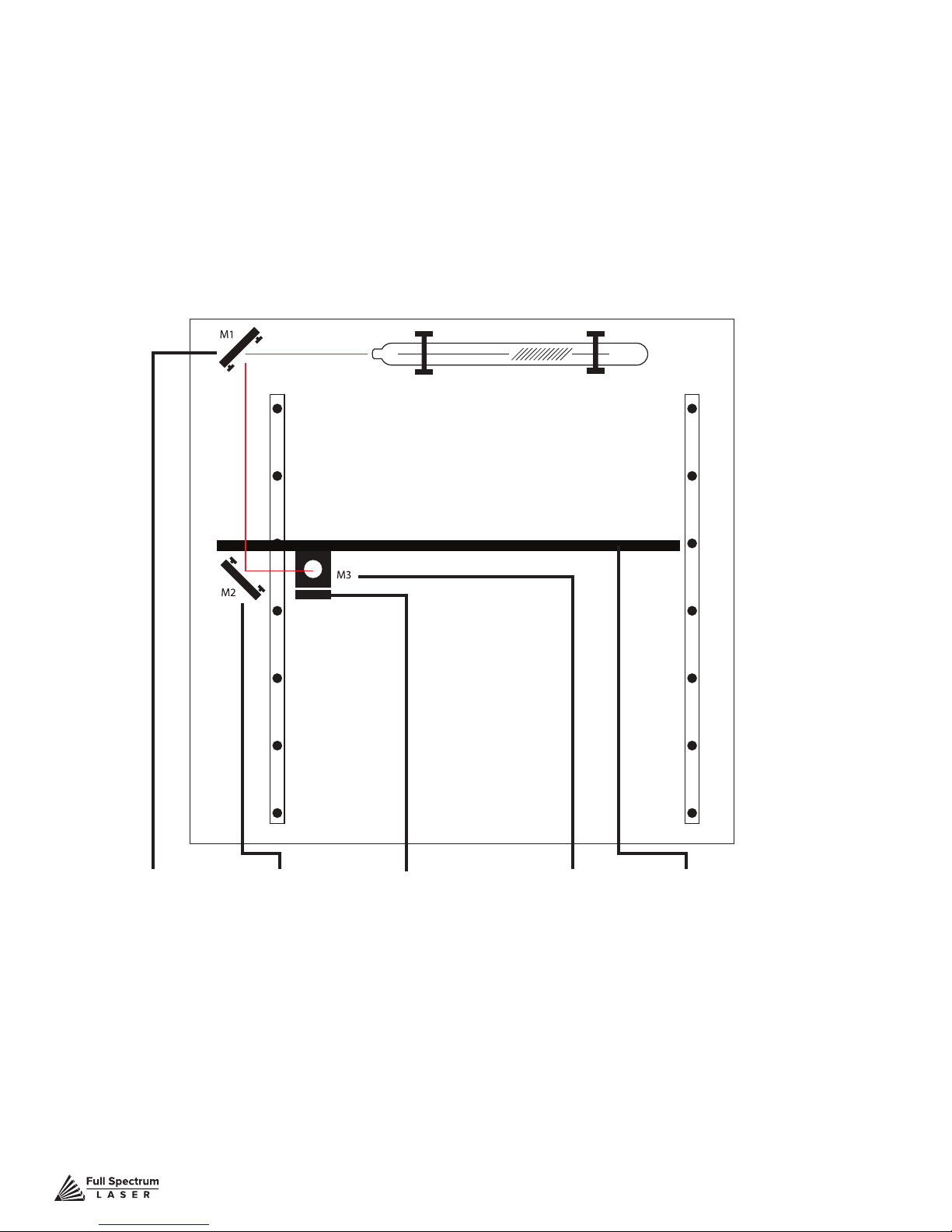
The mirror alignment procedure goal is to rst align the visible red beam with the invisible CO2 laser
beam then use the red beam as the primary indicator for alignment. The idea is that when the laser
is not aligned, you will have two black dots from the test res in the top and bottom positions. The
red laser pointer is aligned with the invisible laser pointer to give you immediate feedback on the
mirror, the black dots will be exactly on top and this axis is aligned. The goal is to have the two black
dots overlap exactly. It is not necessary that the dots be in the center of the mirror but they should be
somewhere on the mirror.
Figure 4.4
5 Stages:
1. PREP
2. ALIGN LASER OUTPUT TO MIRROR #1
3. ALIGN MIRROR #1 TO MIRROR #2
4. ALIGN MIRROR #2 TO MIRROR #3
5. FOCUS LENS ALIGNMENT
Technical Support is available from 8am to 5pm (PST) M - F at [email protected].
Focus Lens
Mirror #3Mirror #2Mirror #1
X-Gantry
Tools Needed:
THERMAL PAPER
2.5 MM. HEX WRENCH
30
Page 32
Stage 1 Prep
Prepare your tools and workspace.
1. Safety First: Be aware of all safety procedures and precautions before continuing.
2. Power On Laser Cutter: The machine must be powered on to continue this procedure. Turn
on the machine by hitting the power switch. Allow the machine time to boot up the touch screen
operating system.
3. Unlock Driver Motor: The driver motor needs to be Unlocked to allow manual “jog” control.
On the touch screen, press the “Locked” icon to switch to “Unlocked” position. The button will now
display the “Unlocked” icon.
4. Gather Tools: A 2.5 mm hex wrench and a supply of thermal paper are required to perform the
mirror alignment procedure (if required).
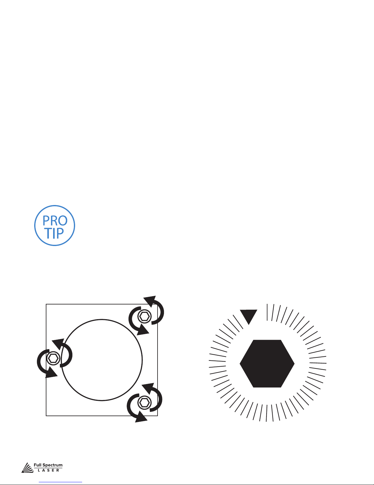
PRO TIP! DO NOT over-tighten or over-loosen adjustment screws.
Tightening or loosening any of the three adjustment screws on the
mirrors or the red dot diode will move the position in a particular
direction depending on the positioning of the other screws. Some
experimenting is required to understand the relationship of each screw
and how adjusting one affects the red dot’s positioning. When adjusting
the screws, use the absolute minimum turn of the hex wrench to move
the red dot or the mirror into position.
Figure 4.5
Technical Support is available from 8am to 5pm (PST) M - F at [email protected].
31
Page 33
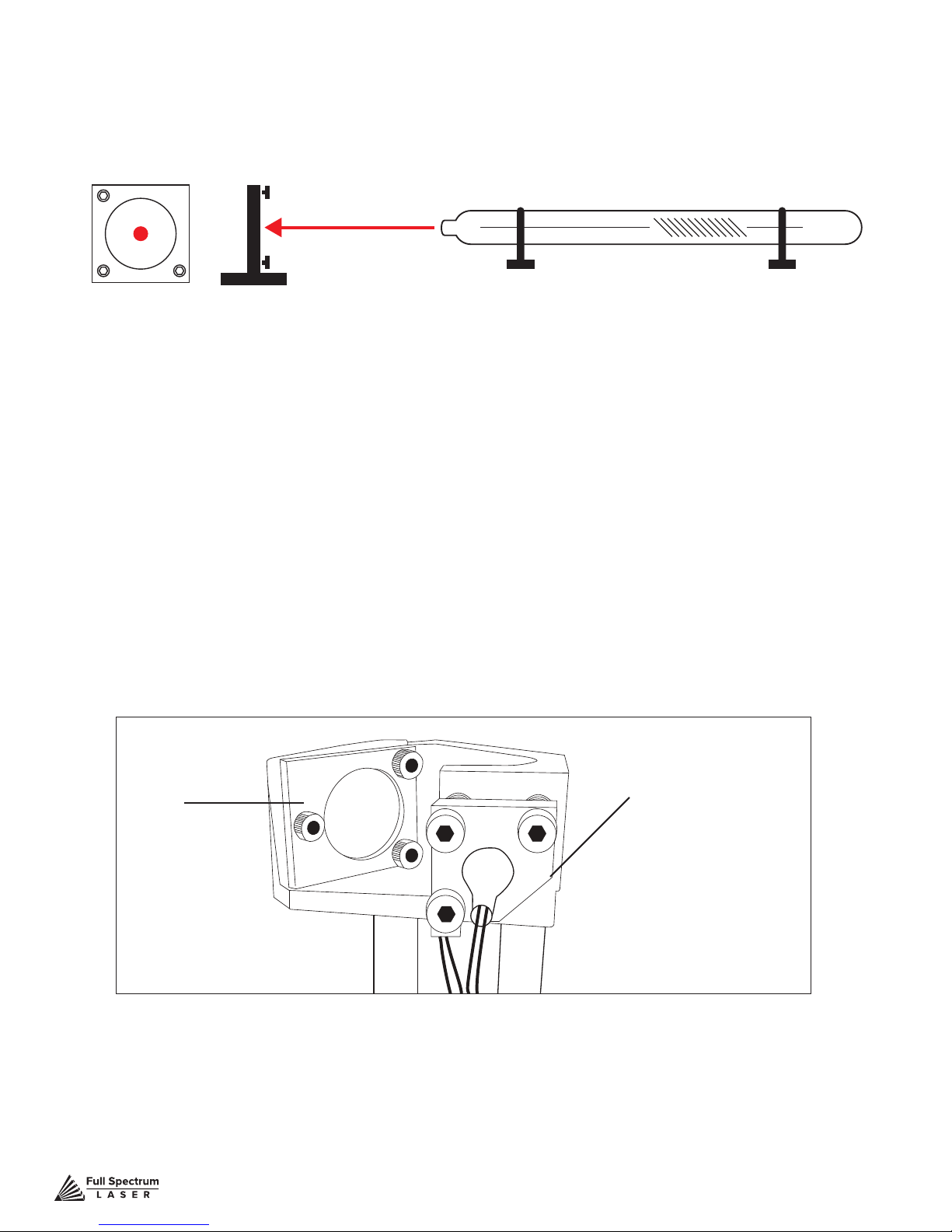
Stage 2 Align Laser Output To Mirror #1
Conceptually, you will be aligning the invisible cutting beam with the visible red beam diode and
making sure they hit each mirror precisely. Once again, remember to check your mirror alignment
BEFORE starting this procedure as it is likely unnecessary if the laser tube was pre-installed in your Muse.
Figure 4.6
1. Open the Safety Lid: You will need to access the interior of the machine.
2. Place Thermal Paper: Take a small piece of thermal paper (approx. 15 mm should be plenty)
and place it rmly over Mirror #1.
3. Close Safety Lid: Safety measures should make it impossible to re the laser with the safety
lid open. Regardless, never attempt to re the laser with safety lid open.
4. Test Fire the Laser: Press the Fire Laser Icon Button on the touch screen. You will see a burn
mark on the thermal paper. It should hit the mirror in the middle.
5. Adjust Red Beam: Using your 2.5m hex wrench, make micro adjustments to the three
adjustment screws of the red beam diode, and position the red dot exactly over the burn mark.
Mirror #1
Red Beam Diode
Figure 4.7
Technical Support is available from 8am to 5pm (PST) M - F at [email protected].
32
Page 34
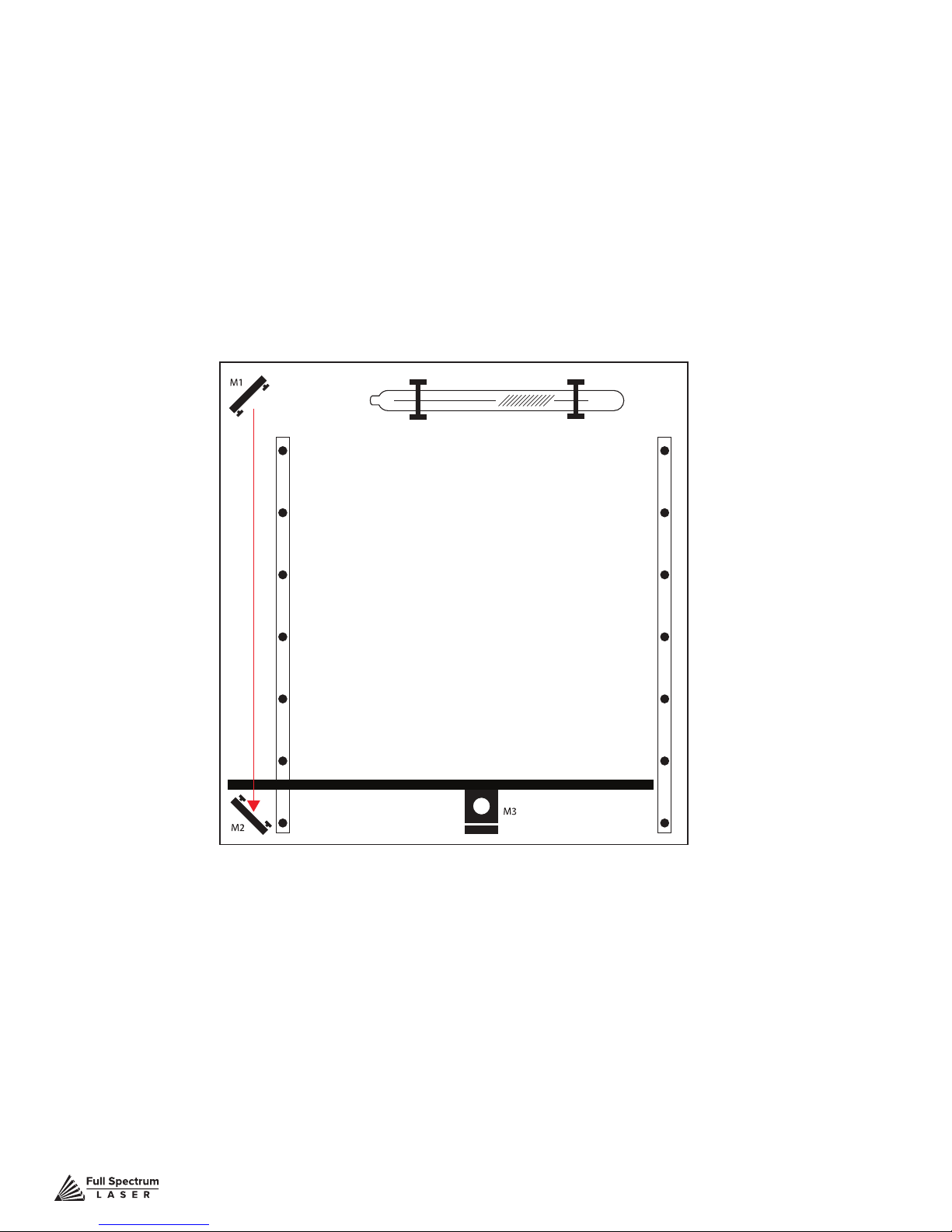
Stage 3 Align Mirror #1 To Mirror #2
Because the 2nd mirror moves along with the X-gantry alignment must be checked between
mirrors #1 and #2.
1. Open Safety Lid: You will need to access the interior of the machine.
2. Place Thermal Paper: Take a small piece of thermal paper (approx. 15 mm should be plenty)
and place it rmly over Mirror #2.
3. Position X-Gantry “Far”: Jog or manually position the X-Gantry to the lowest position
(as shown in Figure 4.7).
Figure 4.8
4. Close Safety Lid: Safety measures should make it impossible to re the laser with the safety
lid open. Regardless, never attempt to re the laser with safety lid open.
5. Test Fire the Laser: Press the Fire Laser Icon Button on the touch screen. You will see a burn
mark on the thermal paper.
6. Adjust Red Beam. Using your 2.5m hex wrench, make micro adjustments to the three
adjustment screws of the red beam diode, and position the red dot exactly over the burn mark. Do not
worry if this places the red dot away from the center of the mirror, we will adjust to center in the next step.
Technical Support is available from 8am to 5pm (PST) M - F at [email protected].
33
Page 35
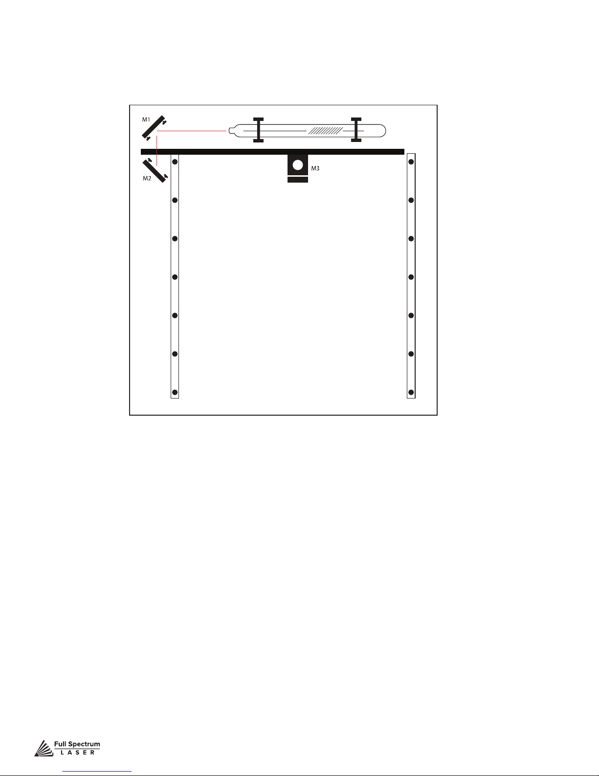
7. Reposition the X-Gantry to “Close” Position: Now that we have a burn mark on our
thermal paper from a “far” ring of the laser, we want to re the laser from the closest position. Move
the X-Gantry to the upper most position in the machine and test re again.
Figure 4.9
8. Re-Position X-Gantry back to “Far”: Jog or manually position the X-Gantry to the far
position where you did the rst test re. (as shown in Figure 4.7).
9. Check Results: There should be two observable burn marks on the thermal paper. If they overlap
perfectly you can move on to the next mirror. If they are apart, adjust the three 2.5mm hex screws on
Mirror #1 (not the red beam diode) to move the second burn mark over the red beam.
10. Repeat Until Aligned: Check your results by repeating this process until the two burn marks
are both center and perfectly overlapping each other. Once aligned, you will repeat this procedure on
the next mirror.
Technical Support is available from 8am to 5pm (PST) M - F at [email protected].
34
Page 36
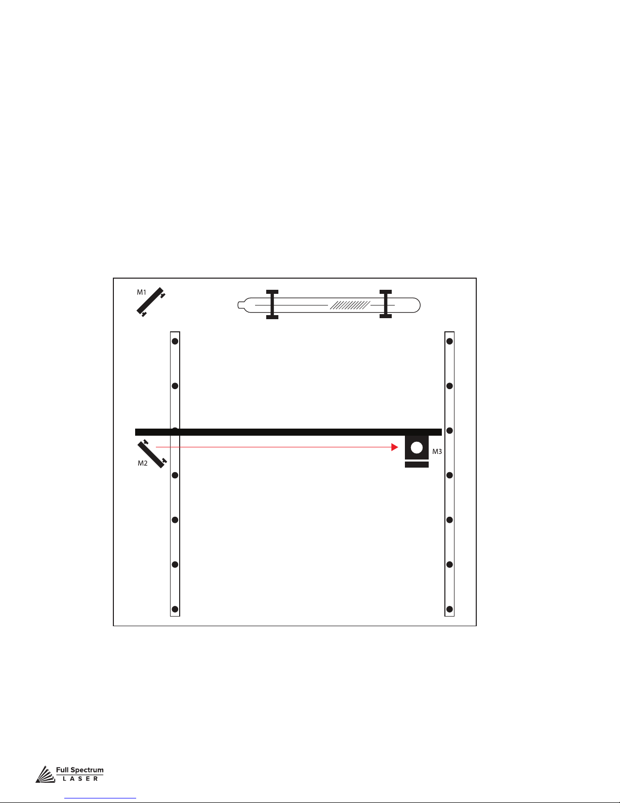
Stage 4 Align Mirror #2 To Mirror #3
The 3rd mirror is mounted on the laser head assembly and slides along the X-gantry rail.
1. Open Safety Lid: You will need to access the interior of the machine.
2. Place Thermal Paper: Take a small piece of thermal paper (approx. 15 mm should be plenty)
and place it rmly over Mirror #3.
3. Position the Gantry Bar: Place the gantry bar in the center of the work bed, as shown in the
diagram below.
4. Position Laser Head “Far”: Jog or manually position the laser head to the far right (as shown
in diagram). This is the farthest position of the Mirror #3 from Mirror #2.
Figure 4.10
5. Close Safety Lid: Safety measures should make it impossible to re the laser with the safety lid
open. Regardless, never attempt to re the laser with safety lid open.
6. Test Fire the Laser: Press the Fire Laser Icon button on the touch screen. You may need to
re the laser twice to see the burn mark on the thermal paper.
Technical Support is available from 8am to 5pm (PST) M - F at [email protected].
35
Page 37
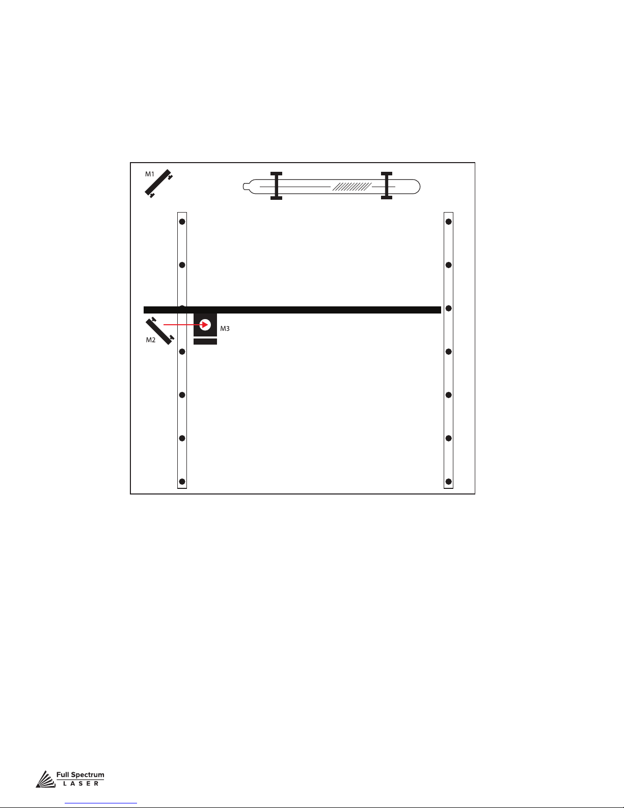
7. Adjust Red Beam: Using your 2.5m hex wrench, make micro adjustments to the three
adjustment screws of the red beam diode, and position the red dot exactly over the burn mark.
8. Reposition the Laser Head to “Close” Position: Now that we have a burn mark on our
thermal paper from a “far” ring of the laser, we want to re the laser from the closest position. Move
the laser head to the far left of the machine and test re again.
Figure 4.11
9. Re-Position X-Gantry back to “Far”: Jog or manually position the laser head to the far
right where you did the rst test re.
10. Check Results: There should be two observable burn marks on the thermal paper. If they
overlap perfectly you can move on to the next mirror. If they are apart, adjust the three 2.5mm hex
screws on Mirror #2 (not the red beam diode) to move the burn mark over the red beam.
11. Repeat Until Aligned: Check your results by repeating this process until the two burn marks
are both center and perfectly overlapping each other.
Technical Support is available from 8am to 5pm (PST) M - F at [email protected].
36
Page 38
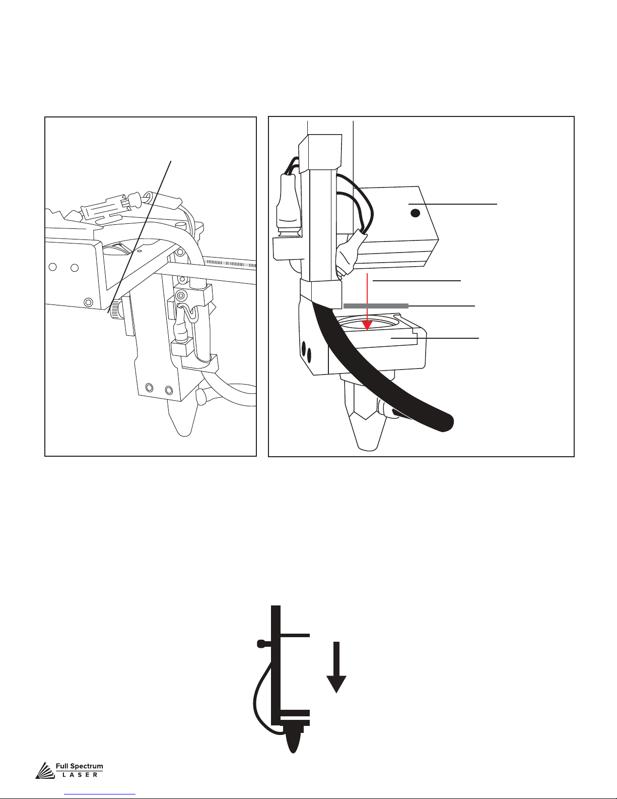
Stage 5 Focus Lens Alignment
The focal lens is located at the bottom of the laser head assembly. For proper alignment, the laser
beam should always be hitting the center of the focal lens, regardless of the position of the cutting
head in the machine.
Thumb Screw
Mirror #3
Laser Path
Thermal Paper
Focus Lens
Figure 4.12 Figure 4.13
1. Open Safety Lid: You will need to access the interior of the machine.
2. Place Thermal Paper: Put a piece of thermal paper on top of the focus lens. It is best to use a
slightly smaller piece of thermal tape to fully see the outline of the lens.
3. Position Focus Lens “Far”: Use the thumb screw to loosen and position the focus lens as
far down as it will go.
Figure 4.14
Technical Support is available from 8am to 5pm (PST) M - F at [email protected].
37
Page 39

4. Close Safety Lid: Safety: measures should make it impossible to re the laser with the safety
lid open. Regardless, never intentionally re the laser with safety lid open.
5. Test Fire the Laser: Press the Fire Laser Icon button on the touch screen. You will see a burn
mark on the thermal paper.
6. Adjust Red Beam: Using your 2.5m hex wrench, make micro adjustments to the three
adjustment screws of the red bean diode, and position the red dot exactly over the burn mark.
7. Reposition the Focus Lens to “Close” Position: Now that we have a burn mark on our
thermal paper from a “far” ring of the laser, we want to re the laser from the closest position. Move
the focus lens as far up as it will go. Test re the laser again, leaving a second burn mark.
Figure 4.15
8. Re-Position Focus Head back to “Far”: Use the thumb screw to loosen and position the
focus lens as far down as it will go.
9. Check Results: There should be two observable burn marks on the thermal paper. If they
overlap perfectly you can move on to the next mirror. If they are apart, adjust the three 2.5mm hex
screws on Mirror #3 (not the red beam diode) to move the burn mark over the red beam.
10. Repeat Alignment Test: To ensure your laser is aligned, repeat the alignment test by test
ring the laser in all four corners and checking that all the burn marks perfectly overlap each other.
Technical Support is available from 8am to 5pm (PST) M - F at [email protected].
38
Page 40
Focusing
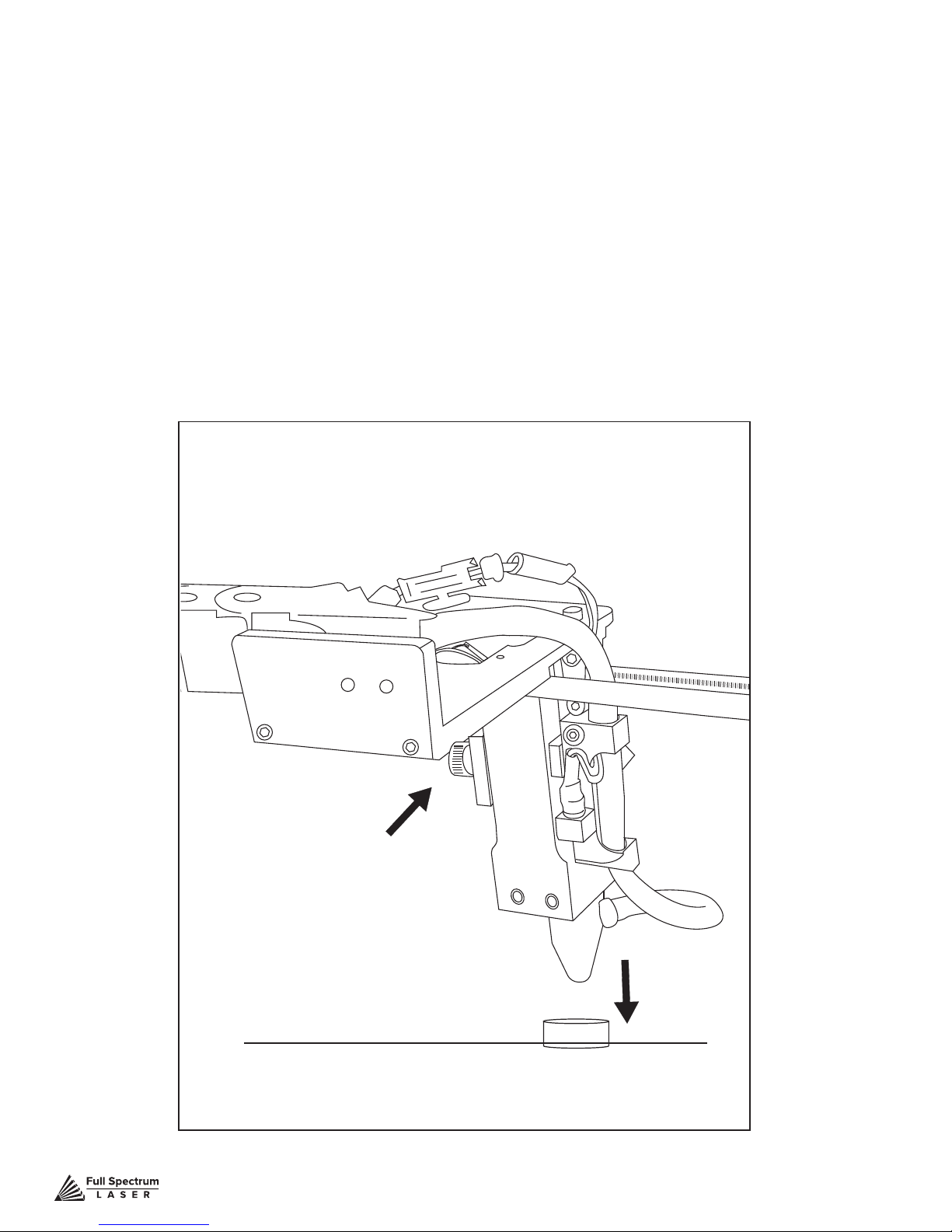
Focusing the Muse laser cutter is quick and easy. Your laser included a billet sized for the
included 2-inch focal length lens. Note that if your Muse has the autofocus feature, focusing is
automatic when the job is run.
1. Place Billet: After inserting your material into the workbed, place the billet on top of the material.
Note that if your material isn’t at, you may need to cut the material in stages, focusing each time to
each new material level.
2. Release Locking Mechanism: Release the locking mechanism on the focus head until the
air assist nozzle rests on top of the billet.
3. Retighten: Retighten the sliding head and remove the billet from the material.
Locking Mechanism
Figure 4.16
Technical Support is available from 8am to 5pm (PST) M - F at [email protected].
Focus Billet
Material
39
Page 41
A
A
B
A
B
C
A
B
C
D
A
B
C
D
E
A
B
C
D
E
F
A
B
C
D
E
F
G
A
B
C
D
E
F
G
I
A
B
C
D
E
F
G
I
H
A
B
C
D
E
F
G
I
H
J
A
B
C
D
E
F
G
I
H
J
K
A
B
C
D
E
F
G
I
H
J
K
L
A
B
C
D
E
F
G
I
H
J
K
L
M
SECTION V. TOUCH SCREEN INTERFACE
A
A
B
A
B
C
A
B
C
D
A
B
C
D
E
A
B
C
D
E
F
A
B
C
D
E
F
G
I
H
J
K
L
A
B
C
D
E
F
G
I
A
B
C
D
E
F
G
I
H
J
A
B
C
D
E
F
G
A
B
C
D
E
F
G
I
H
A
B
C
D
E
F
G
I
H
J
K
A
B
C
D
E
F
G
I
H
J
K
L
M
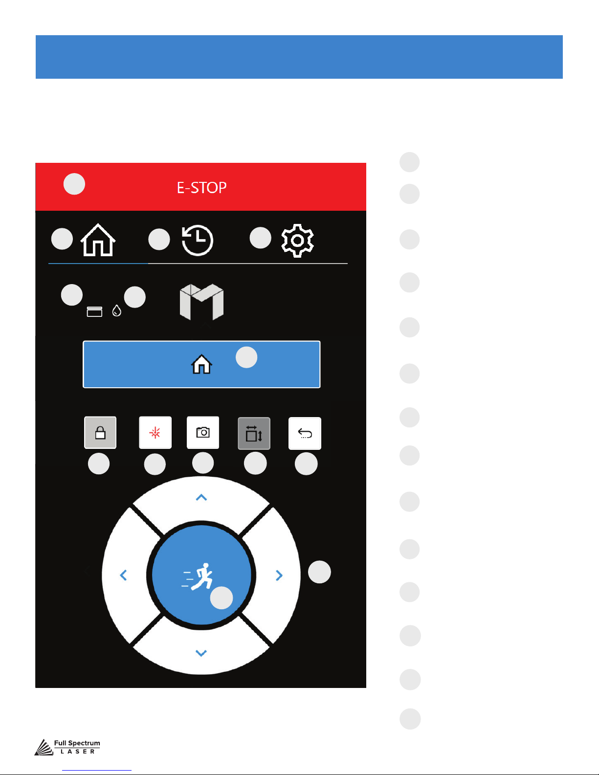
Muse’s touch panel allows you to control the basic functions of your laser without needing to connect
to a computer. This is very convenient during alignment and testing procedures. To actually run jobs,
you will need to access the RetinaEngrave 3.0 software (see Installations and Assembly Section.)
E-STOP
A
Instantly stop any action.
A
HOME MENU
B
Returns to the main Home
Screen from any sub-screen
B
E
Figure 5.1
C
D
F
JOB HISTORY
C
Accesses Job History
sub-screen.
SETTINGS
D
Accesses the Settings
sub-screens.
LID OPEN / CLOSE
E
Indicates lid is opened
or closed.
G
WATER INDICATOR
F
Indicates water system
is running properly.
HOME LASER
G
Instantly homes the laser
LOCKED/UNLOCKED
H
H
I
J
K
L
M
N
M
Technical Support is available from 8am to 5pm (PST) M - F at [email protected].
Lock or unlock the gantry
for auto or manual homing
TEST FIRE
I
Test re the laser. Used for
mirror alignments and testing.
CAMERA
J
Instructs camera to
image workbed
JOG PERIMETER
K
Laser automatically JOGs the
extent of the current project.
RETURN TO POSITION
L
Return gantry to a custom
assigned position
JOG CONTROLS
Jog gantry via control buttons or
manually.
JOG SPEED
N
Switch from slow jog to fast jog
40
Page 42
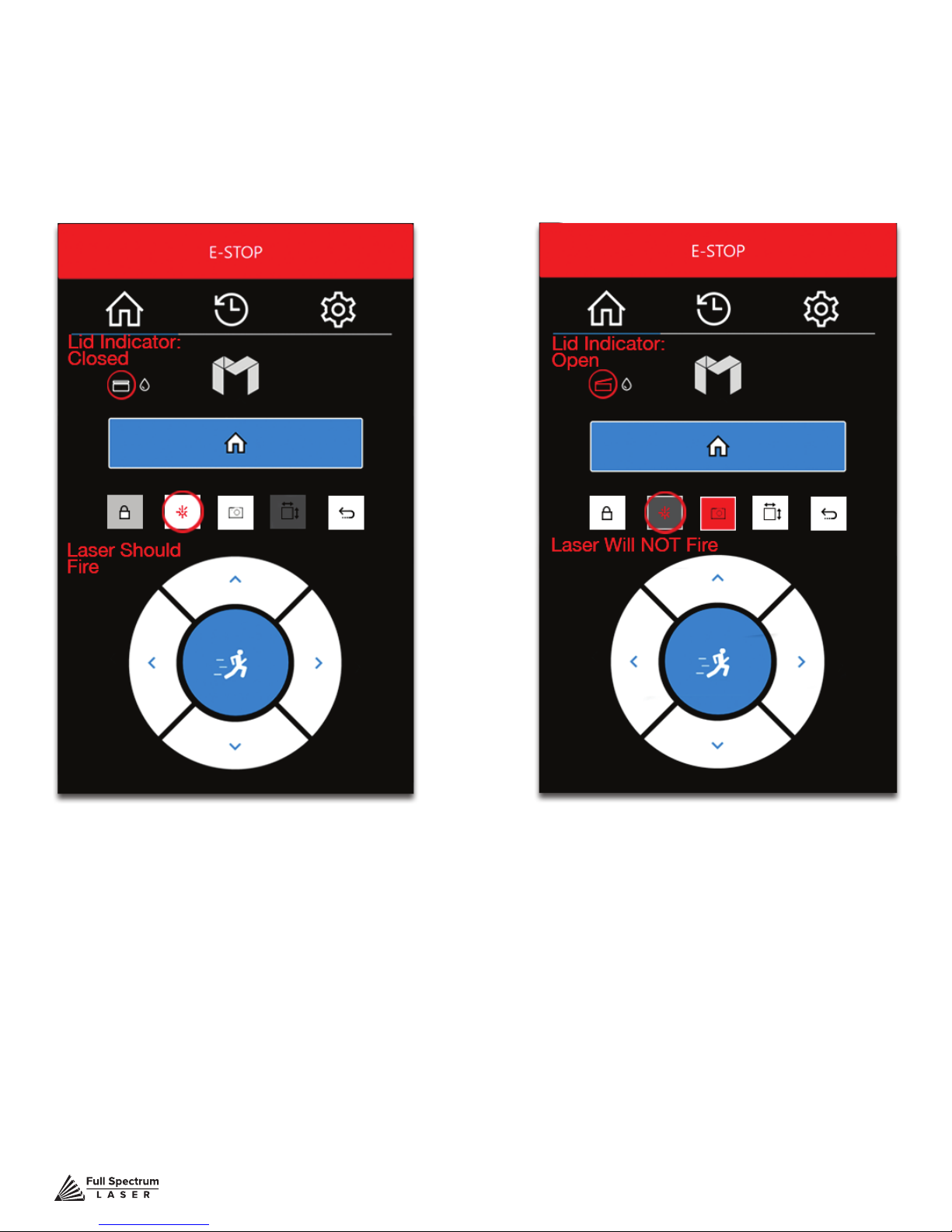
Safety Override Lid Failsafe
As a safety feature, the lid has a magnetic failsafe that disconnects the laser when the lid is open.
this will be indicated by your touch screen display like so.
Figure 5.2 Figure 5.3
Be sure your lid is closed when you try to re the laser. If the lid is closed and the laser still does not
re, check that the lid magnet is touching the proper base magnet and that wires are connected.
Technical Support is available from 8am to 5pm (PST) M - F at [email protected].
41
Page 43
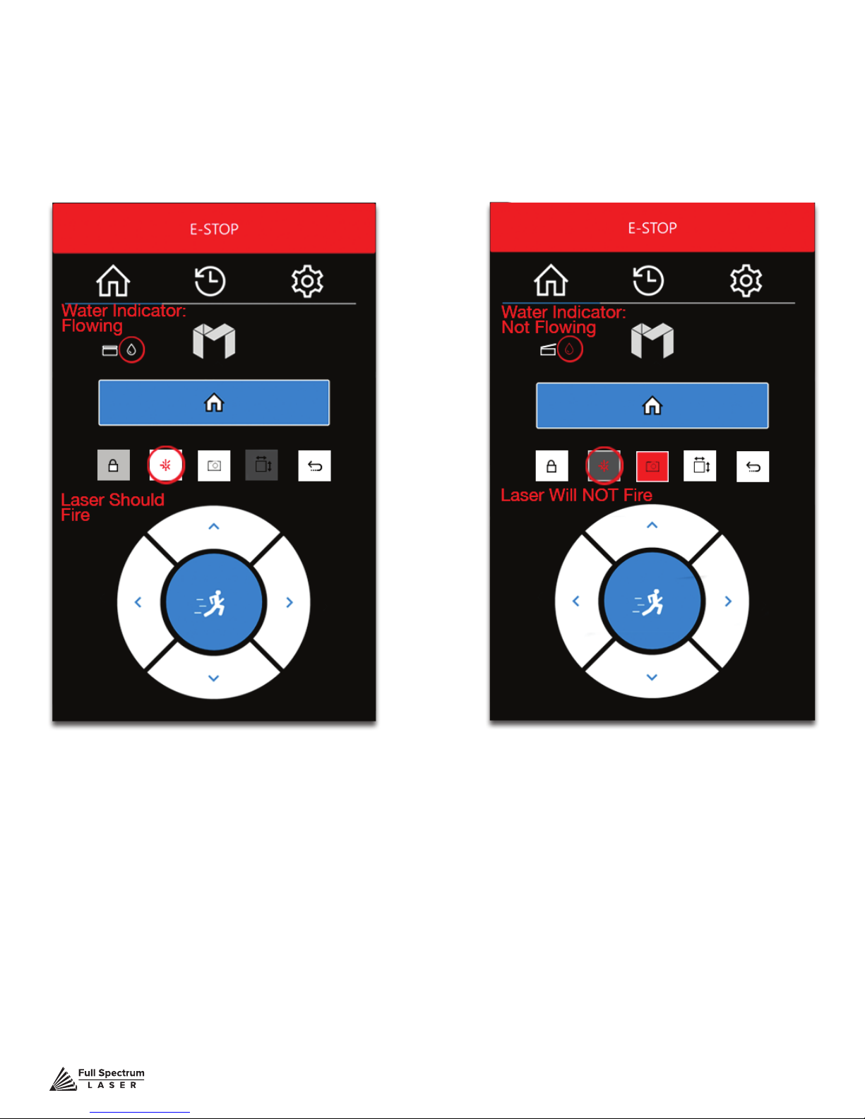
Safety Override Waterow Failsafe
The laser will not re unless water is owing through the laser tube. The following indicator informs
Muse operators if water is not owing.
Figure 5.4 Figure 5.5
If your touch screen indicates water is not owing through the laser tube, check your water tube
connections and make sure your tubes and water chiller are assembled correctly. More than likely,
you have the water tubes reversed.
Technical Support is available from 8am to 5pm (PST) M - F at [email protected].
42
Page 44
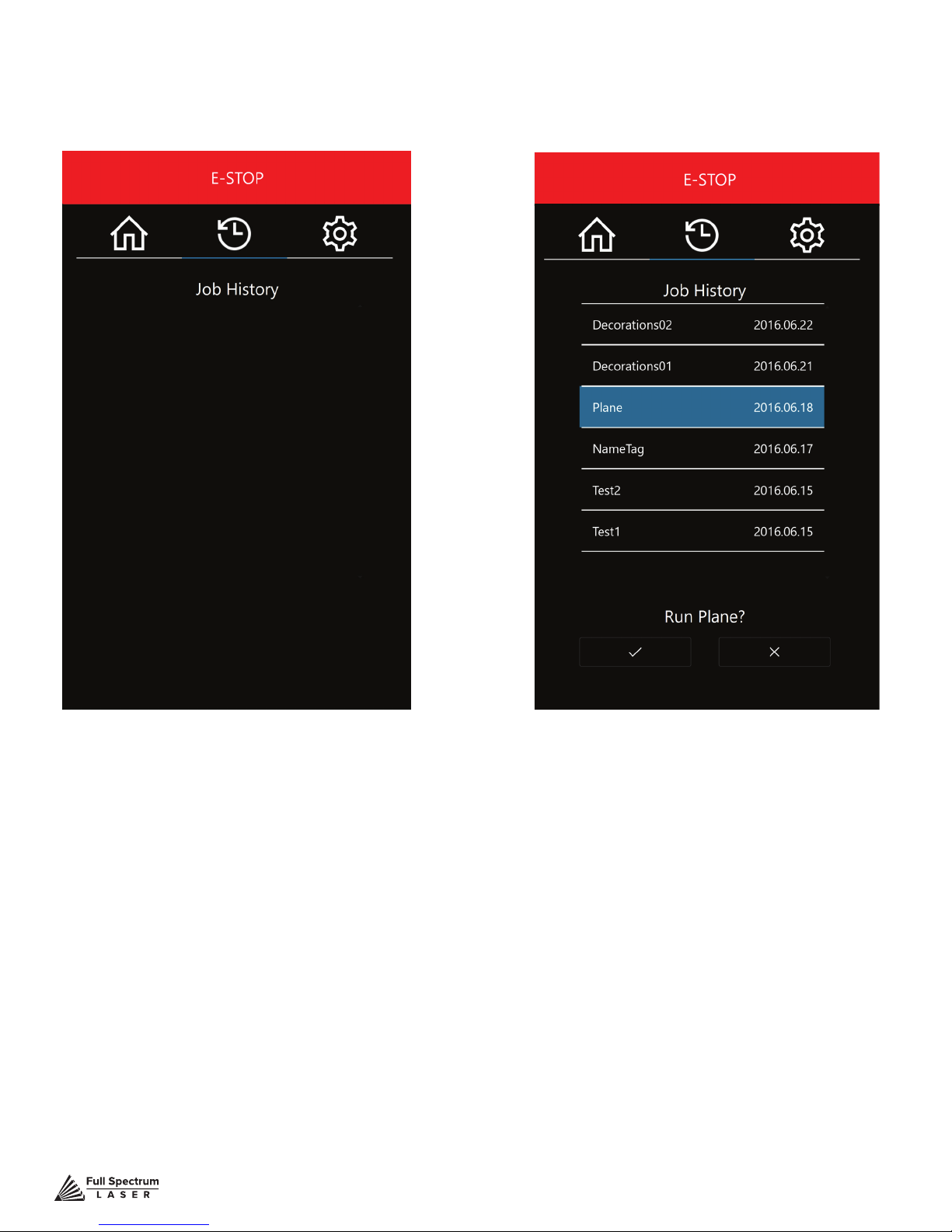
Job History Screen
There are many accessible sub-screens for Muse’s touch screen. Each is detailed separately below.
Figure 5.6 Figure 5.7
HISTORY
No jobs in history. This will change once you
start your rst project.
HISTORY SELECTION
Scroll through all previous job history. Jobs
can be selected and run by highlighting the
job and pressing the check.
Technical Support is available from 8am to 5pm (PST) M - F at [email protected].
43
Page 45
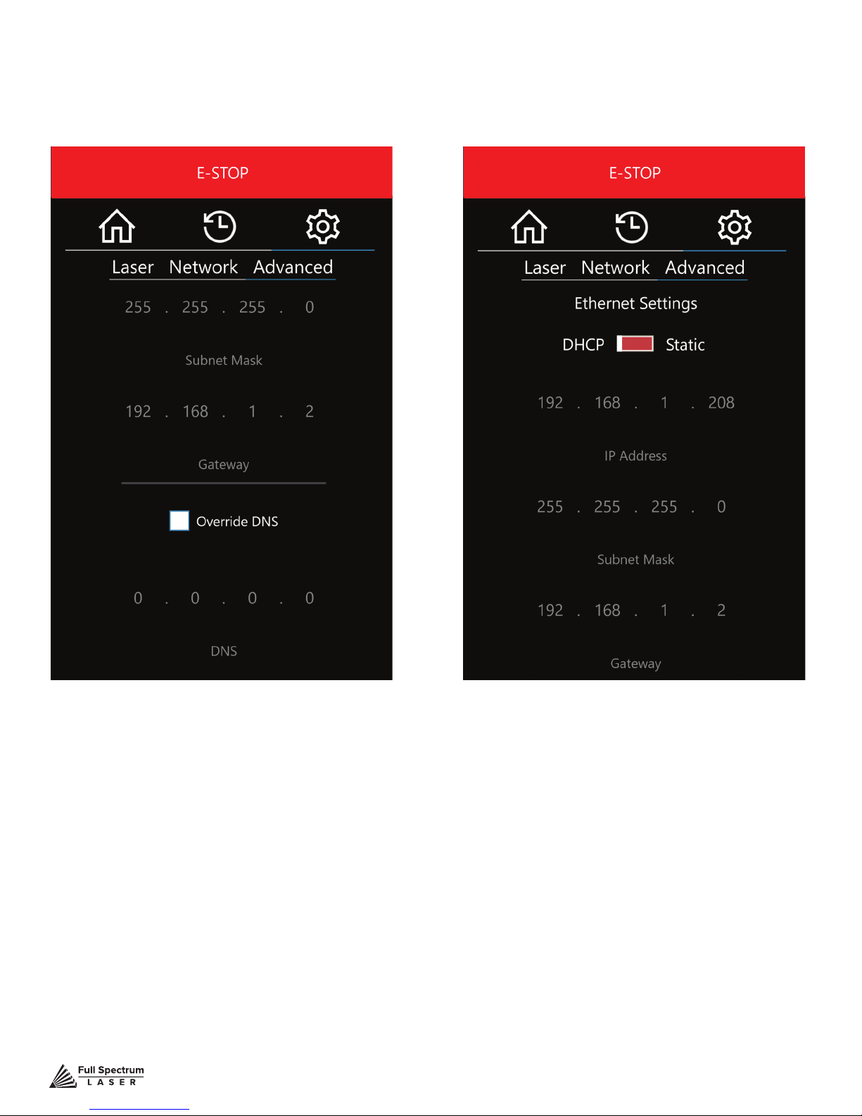
Network Settings Screen
Figure 5.8 Figure 5.9
DOMAIN NAME SERVER SETTINGS
Automatically scan and connect to local
network or input custom settings.
Technical Support is available from 8am to 5pm (PST) M - F at [email protected].
ETHERNET SETTINGS
Manually specify network settings or
change DHCP.
44
Page 46
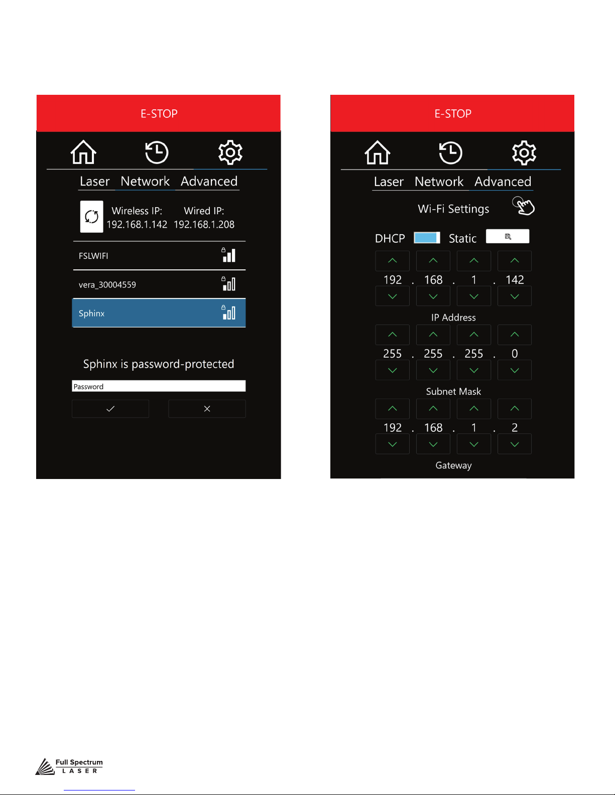
Network Settings (Cont.) Screen
Figure 5.10 Figure 5.11
Wi-Fi SELECTION
Scan and connect to a Wi-Fi network. If the
network is password protected, you will need
to enter that password.
Technical Support is available from 8am to 5pm (PST) M - F at [email protected].
Wi-Fi AUTO/STATIC
Change the conguration of Wi-Fi
settings or choose DHCP settings.
45
Page 47
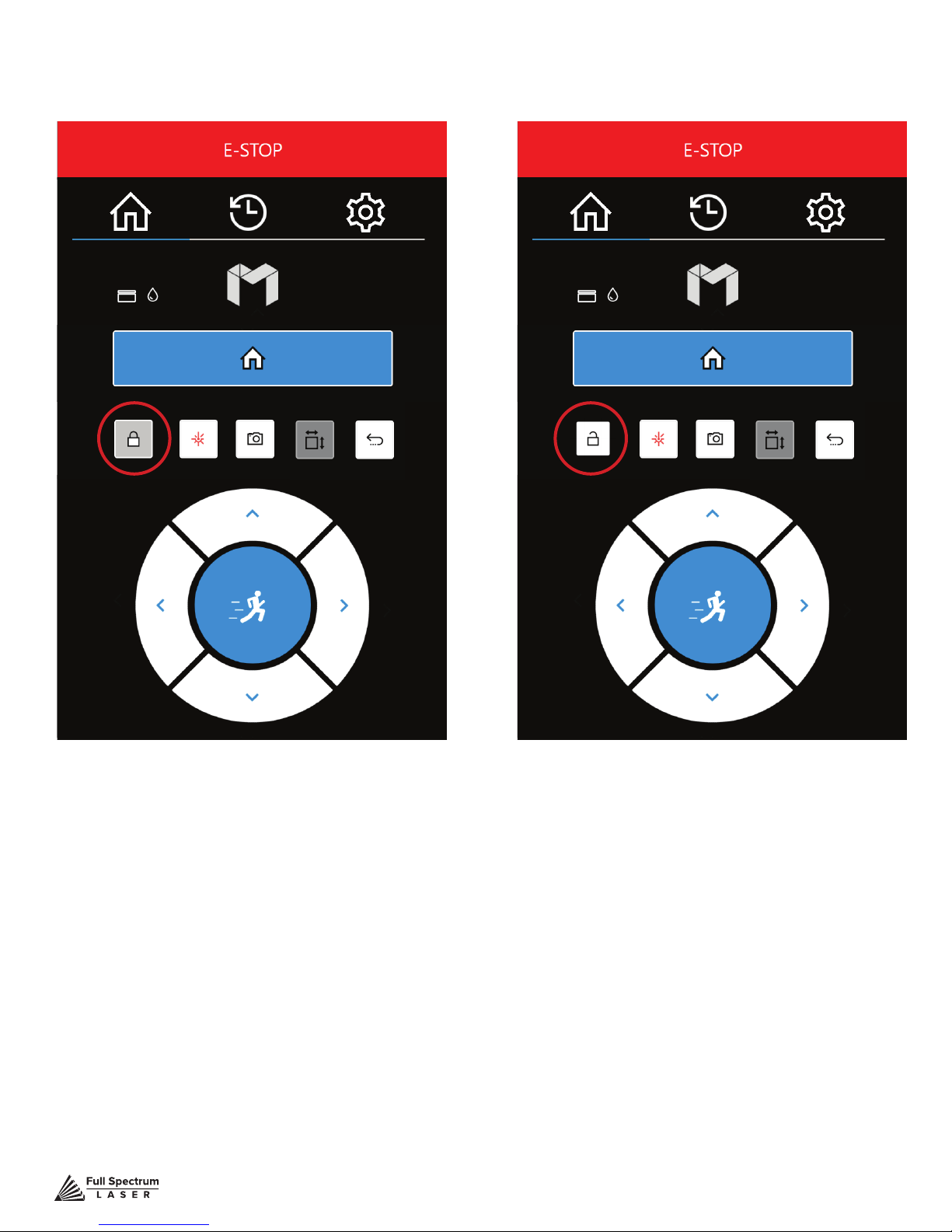
Lock / Unlock Screens
Figure 5.12 Figure 5.13
LOCKED SCREEN
Indicates the gantry is locked. When locked,
user may not manually move the gantry.
Technical Support is available from 8am to 5pm (PST) M - F at [email protected].
UNLOCKED SCREEN
Indicates the gantry is unlocked. When
unlocked, user may manually move the gantry.
46
Page 48
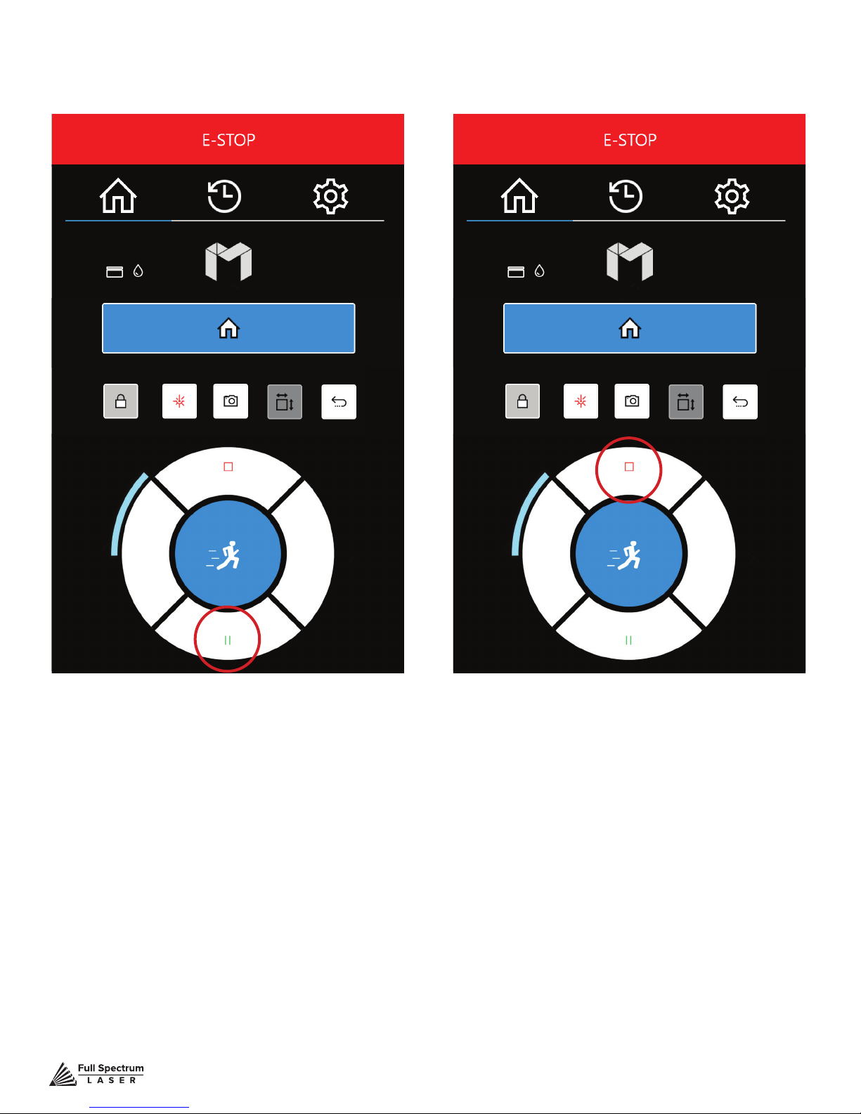
Job Progress Options
Figure 5.14 Figure 5.15
JOB IN PROGRESS (PAUSE)
Indicates a job is in progress. Pause by
pressing the play / pause button.
Technical Support is available from 8am to 5pm (PST) M - F at [email protected].
JOB IN PROGRESS (STOP)
Touch the red stop button to stop a
job in progress.
47
Page 49
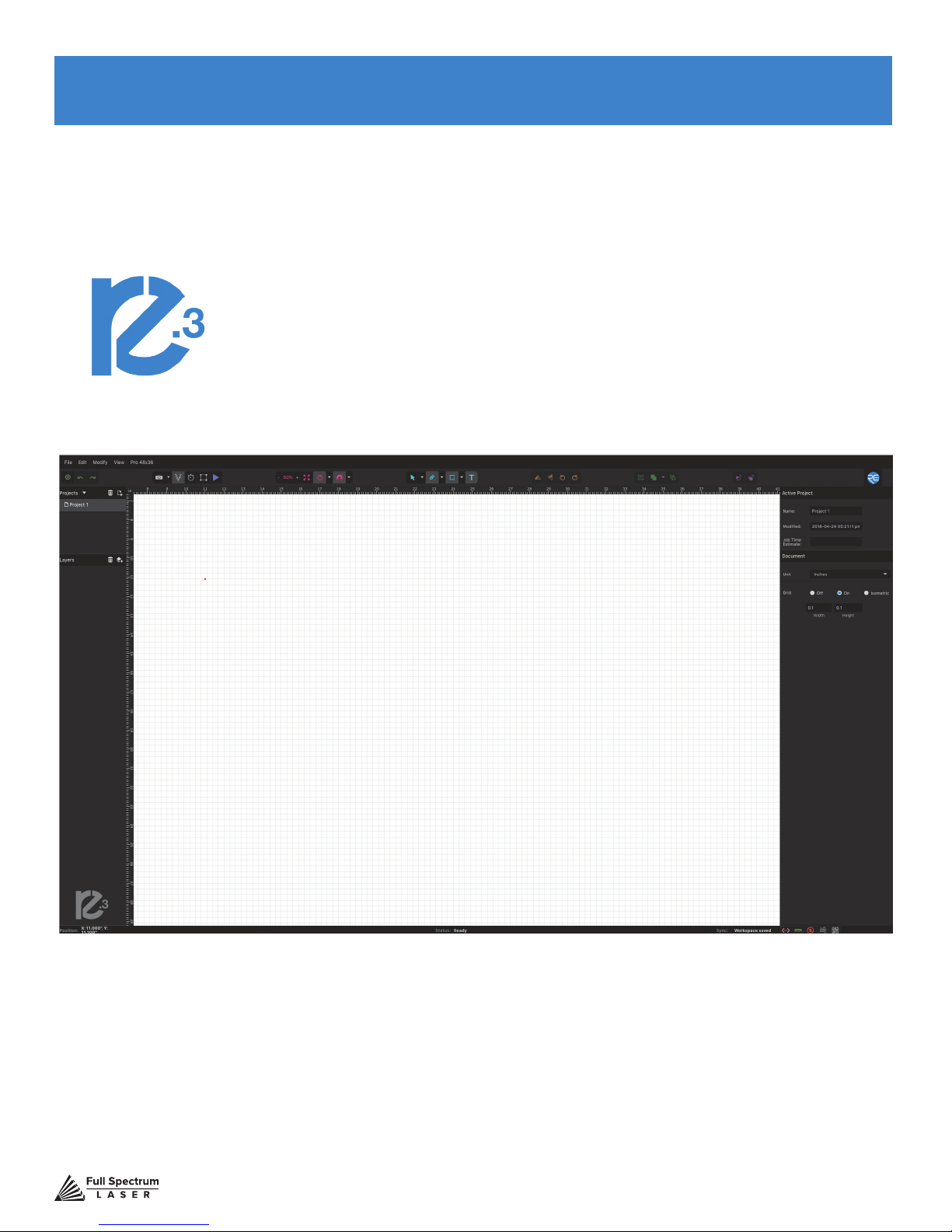
SECTION VI. SOFTWARE
Using RetinaEngrave 3.0 Software
In this section you will be introduced to the major interface features of RetinaEngrave 3.0.
Figure 6.1
Technical Support is available from 8am to 5pm (PST) M - F at [email protected].
48
Page 50

Top Menu
File Menus
New Project (Alt+N): Start a new project.
New From Clipboard (Shift+Ctrl+Alt+N): Start a new project from the clipboard.
Load Project from File (Ctrl+O): Load a project from a saved le.
Place/Import: Import and place a le.
Import fonts: Add fonts from outside source.
Export Project to File (Shift+Ctrl+E): Export to a le.
Submit Support Ticket: Auto send a support request ticket.
Edit Menus
Undo Delete Layer or Item (Ctrl+Z): Reverse previous project command.
Redo (Shift+Ctrl+Z): Reverse your last undo.
Cut (Ctrl+X): Selected object or item is removed.
Copy (Ctrl+C): Copy some portion of an object or item.
Paste (Ctrl+V): Paste a copied or cut portion of an object or item.
Delete (Del): Delete selected object or item.
Paste In Place (Shift+Ctrl+V): Paste a copied object or item in same location.
Paste Inside Selection: Paste a copied object or item inside selected area.
Paste Style (F4): Paste and match style.
Duplicate (Ctrl+D): Create a copy of a selected object.
Clone (Shift+Ctrl+D): Create an exact copy or ‘clone’ of an object.
Select All (Ctrl+A): Select all items in work screen.
Deselect All (Shift+Ctrl+D): All items in work screen are deselected.
Invert Selection (Ctrl+I): Items previously selected are now unselected and items
unselected are selected.
Select by Font Type: Select item by font type.
Settings: Displays settings menu.
Modify Menus
Arrange
Send to Front (Shift+Ctrl+Up): Send an object to the front layer.
Bring Forward (Ctrl+Up): Send an object one layer forward.
Send Backward (Ctrl+Down): Send an object one layer backwards.
Send to Back (Shift+Ctrl+Down): Send an object to the back layer.
Align
Align Left: Align object to the left.
Align Center: Align object to center.
Align Right: Align object to right.
Align Top: Align object to top.
Align Middle: Align object to middle.
Technical Support is available from 8am to 5pm (PST) M - F at [email protected].
49
Page 51

Align Bottom: Align object to bottom.
Same Width: All selected objects convert to same width.
Same Height: All selected objects convert to the same height.
Distribute Horizontally: Evenly arrange selected objects horizontally.
Distribute Vertically: Evenly arrange selected objects vertically.
Snap to Full Units: Snap to grid as full units.
Snap to Half Units: Snap to grid as half units.
Transform
Rotate 45° Left: Rotate selected object left 45°.
Rotate 90° Left: Rotate selected object left 90°.
Rotate 180° Left: Rotate selected object left 180°.
Rotate 45° Right: Rotate selected object right 45°.
Rotate 90° Right: Rotate selected object right 90°.
Rotate 180° Right: Rotate selected object right 180°.
Flip Vertical: Reverse selected object’s orientation along vertical axis.
Flip Horizontal: Reverse selected object’s orientation along horizontal axis.
Group Selection (Ctrl+G): Select a group of objects.
Merge Selection (Ctrl+M): Merge a selected group of objects.
Split Selection (Shift+Ctrl+M): Split up a compound shape or object.
Create Compound Shape:
Union: Combine layers into a single compound layer.
Intersection: Combine overlapping layers into a single compound layer.
Subtract: Remove and combine non-overlapping layers into a single compound layer.
Difference: Combine non-overlapping layers into a single compound layer.
Create Nested Compound: Combine compound shapes into a single compound shape.
Path
Join Paths (Ctrl+J): Combine 2 or more selected paths into one compound path.
Split Paths (Shift+Ctrl+J): Split a compound path into its original separate paths.
Convert to Path (Shift+Ctrl+P): Convert a non path to a layer path.
Convert to Raw Path: Convert a path or non path layer to a new path.
Convert to Outline: Create an outline path of a specied size around an object.
Expand/Shrink: Scale an object up or down by a specied amount.
Vectorize Border: Create a vector path of the border of an object.
Rasterize - Convert object to raster
Vectorize Image: Create vector paths of each separate element in an image.
Attach Text to Path: Attach and conform text to a path.
Detach Text from Path: Detach text that is attached to a path.
Simplify Path (Ctrl+Alt+S): Simplify (and smooth) a path to varying degrees of tolerance.
Connect Path Lines: Connect together the ends of 2 or more paths.
Break Curve: Break apart a path at a specied node.
Reverse Order: Reverse the order of nodes in a path.
View
Original View (Ctrl+0): Return the workspace back to the original view state prior to
Technical Support is available from 8am to 5pm (PST) M - F at [email protected].
50
Page 52

zooming or panning.
Fit Selection: Fit the current selection to the viewable page area.
Fit Layer: Fit the currently selected layer to the viewable page area.
Fit All (Alt+Ctrl+0): Fit all layers, whether or not selected, to the viewable page area.
Magnication
+6% - +25600% Magnication: Increase or decrease magnication.
Zoom In (Ctrl++): Enlarges workspace screen detail and size.
Zoom Out (Ctrl+-): Reduces workspace screen detail and size.
View Mode
Full View: Set to full view mode.
Fast View: Set to fast view mode.
Outline View: Set to outline view mode.
Output View: Set to output view mode.
Show Rulers (Ctrl+Alt+R): Toggle rulers on and off.
Show GuideLines (Ctrl+,): Toggle guidelines on and off.
Show Grid (Ctrl+Alt+G): Toggle grid on and off.
Show Tooltips (Ctrl+]): Toggle tooltips on and off.
Show Effects (Ctrl+E): Toggle effects on and off.
Snap To:
Use Snapping (Shift+F10): Enable or disable the snapping feature.
Use Snap Zones: Enable or disable the snap zone feature.
Snap to Grid: Enable or disable the Snap to Grid feature.
Snap to GuideLines: Enable or disable the Snap to GuideLines feature.
Snap to Full Pixels: Enable or disable the Snap to Full Pixels feature.
Snap to Anchor Points: Enable or disable the Snap to Anchor Points feature.
Snap to Shapes: Enable or disable the Snap to Shapes feature.
Snap to Pages: Enable or disable the Snap to Pages feature.
Show Inspector Panel: Toggle inspector panel on and off.
Show Outline Panel: Toggle outline panel on and off.
Toggle Fullscreen (F): Toggle full screen view on and off.
Muse
Capture Workspace: Initiates camera functions.
Clear Last Visual: Remove last camera image.
Trace Background: Used with camera functions to apply vectors to selected area of image.
Estimate Job Time: Give approximate time for job to complete.
Run Perimeter: Laser continuously outlines the border of the current project. Press again to stop
running perimeter.
Run Job: Run your project. When running, “Play” button is replaced with “Pause” and “Cancel”.
Pause Job: Pause the laser from continuing with current project.
Cancel Job: Stop the laser and cancel current operation.
Technical Support is available from 8am to 5pm (PST) M - F at [email protected].
51
Page 53
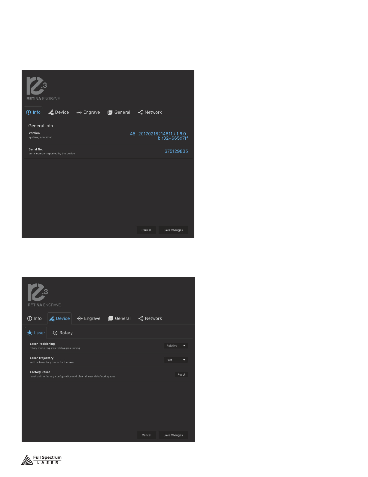
Setting Options
Info.
Displays information regarding your machine.
Device
Displays information regarding device options.
Version: Version information.
Serial No.: Serial number reported by your
device.
Rotary Mode: Informs machine a rotary
device is being used.
Laser Positioning: Toggles between
“Absolute” and “Relative” positioning.
Show Jog Controls: Toggles the display of
jog controls on and off.
Laser Trajectory: Toggle trajectory (Exact,
Fast and Mixed).
Factory Reset: Reset to factory conguration
and clear all user data.
Technical Support is available from 8am to 5pm (PST) M - F at [email protected].
52
Page 54
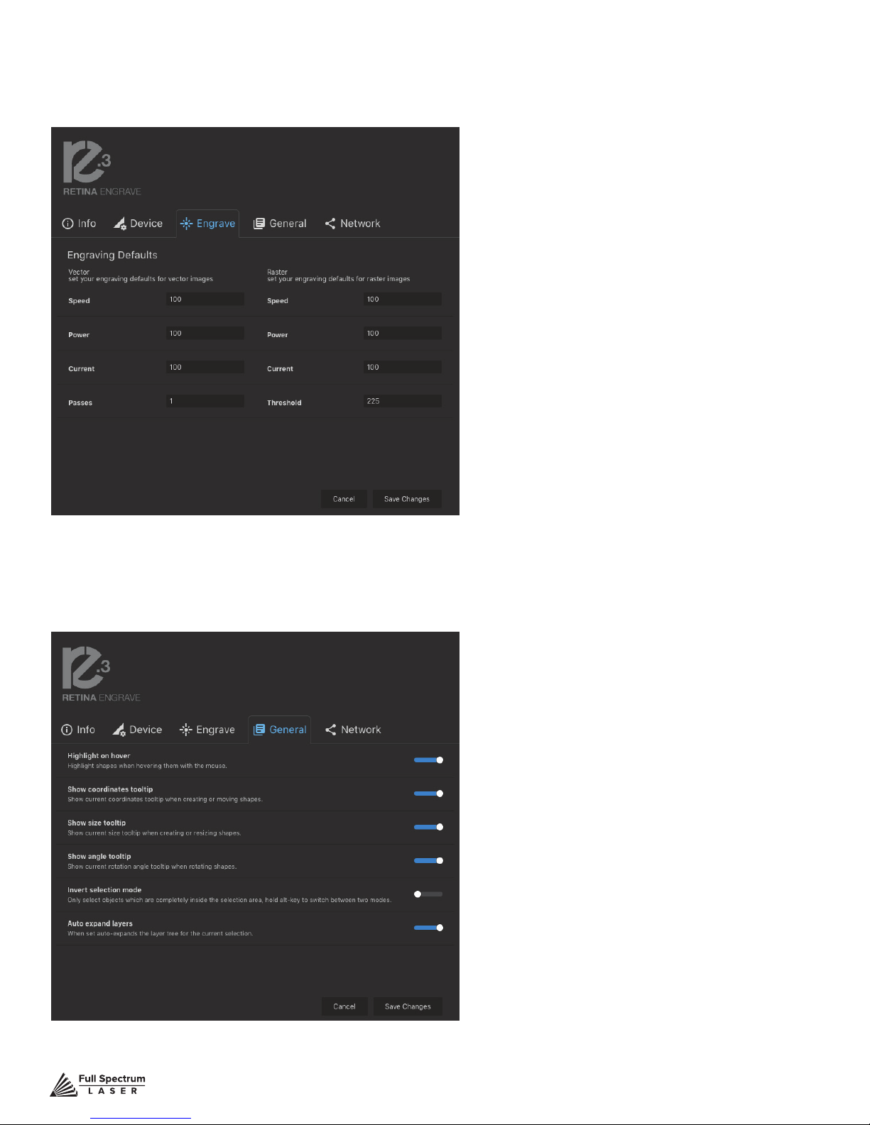
Engrave
Set you engraving defaults for vector and raster images.
Speed: Set speed default from 1 to 100.
Power: Set power default from 1 to 100.
Current: Set current default from 1 to 100.
Passes: Set the number of passes default.
Threshold: Set threshold default value from 0
to 255.
General
Show or hide tooltips and other modes.
Highlight On Hover: Highlight shapes when
hovering with mouse.
Show Coordinates Tooltip: Show
current coordinates tooltip when creating
or moving shapes.
Show Size Tooltip: Show current size
tooltip when creating or resizing shapes.
Show Angle Tooltip: Show current rotation
angle tooltip when rotating shapes.
Invert Selection Mode: Toggle inverted
selection mode on and off.
Auto Expand Layers: When set, auto
expands the layer tree for the current
selection.
Technical Support is available from 8am to 5pm (PST) M - F at [email protected].
53
Page 55

Network
View network information and connect/disconnect
wireless network.
Basic Settings: View basic network
information and connect/disconnect wireless
network.
Wireless IP: Wireless IP information
displayed
Wired IP: Ethernet connection information
displayed
Refresh Network: Click button to refresh
network
Advanced Settings: Set static IPs and
change DNS settings.
Technical Support is available from 8am to 5pm (PST) M - F at [email protected].
54
Page 56
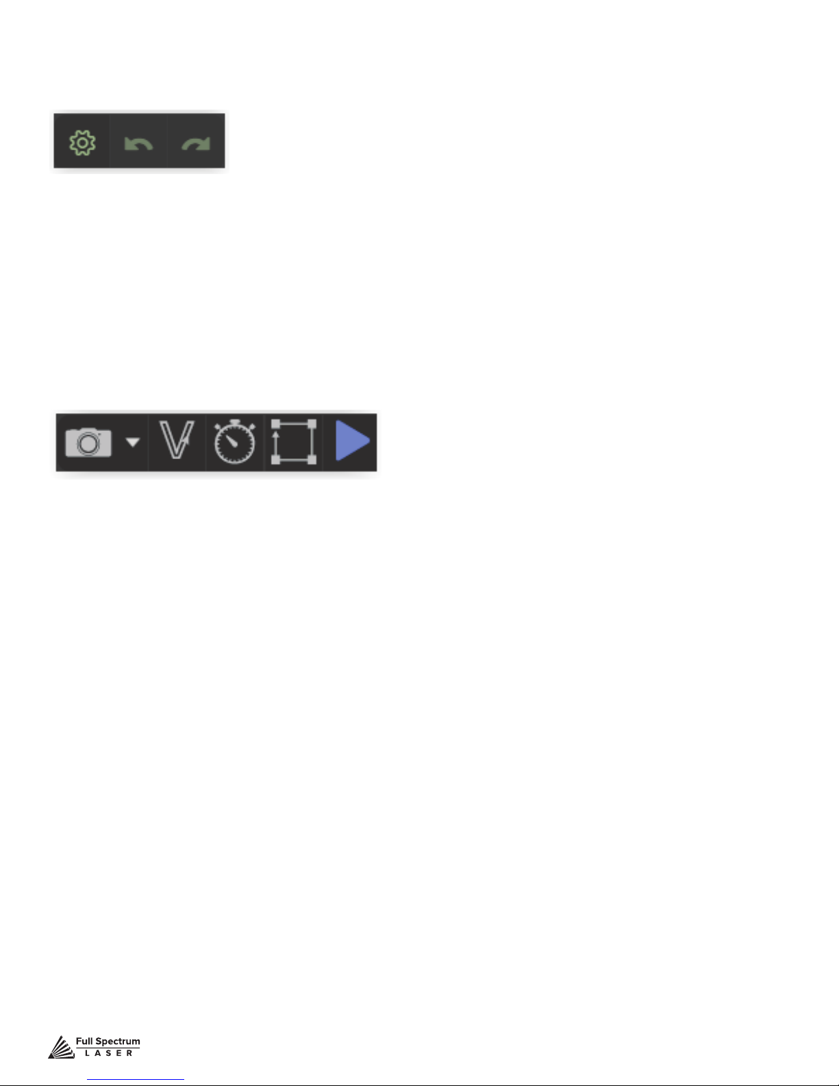
Setting Controls
Access settings options and undo/redo actions.
A. Setting
Goto settings options.
B. UNDO
Reverse your last action.
C. REDO
Reverse your last undo.
Muse Controls
D. CAPTURE
Initiates camera functions ( see using camera functions).
E. VECTORIZE
Apply vector / engraving to selected area of image.
F. JOB TIME ESTIMATE
time for hob to be completed.
G. RUN PERIMETER
Outlines the border of current job.
H. RUN JOB
Run your project. When running “Play” button will be replaced with“Pause” and “Cancel”
Technical Support is available from 8am to 5pm (PST) M - F at [email protected].
55
Page 57
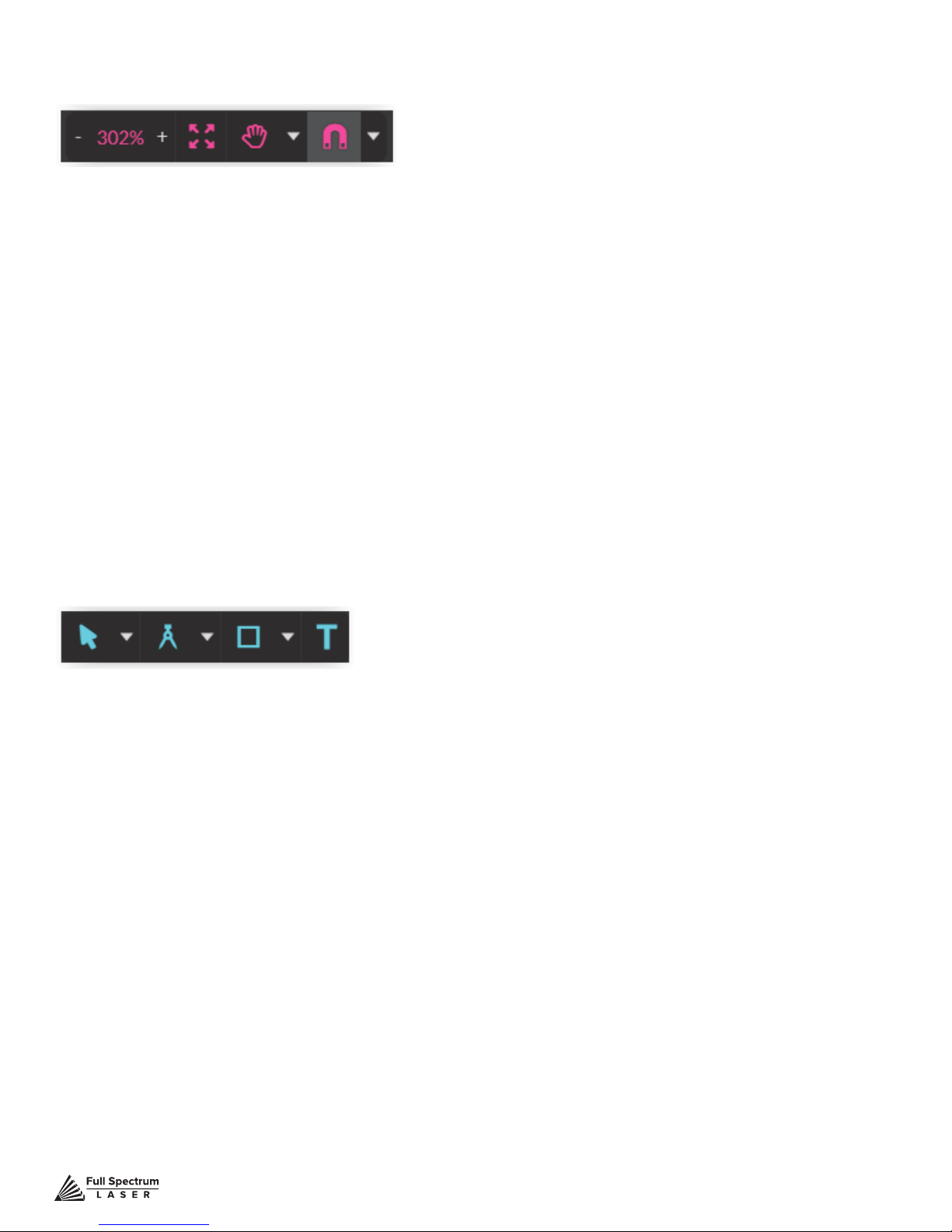
View / Snap Controls
View options or position items on workspace grid.
Zoom (-/+): Enlarges/Reduces workspace screen detail and size.
Fit All
View
Pan (H): Manually pan project window using mouse.
Zoom (Z): Zoom project window using mouse.
Snap
Use Snapping (Shift+F10): Enable or disable the snapping feature.
Use Snap Zones: Enable or disable the snap zone feature.
Snap to Grid: Enable or disable the Snap to Grid feature.
Snap to Guide Lines: Enable or disable the Snap to Guide Lines feature.
Snap to Full Pixels: Enable or disable the Snap to Full Pixels feature.
Snap to Anchor Points: Enable or disable the Snap to Anchor Points feature.
Snap to Shapes: Enable or disable the Snap to Shapes feature.
Snap to Pages: Enable or disable the Snap to Pages feature.
Show Grid: Toggle grid on and off.
Show Guidelines: Toggle guidelines on and off.
Draw Controls
Select (Pointer): Instantly initiate mouse pointer.
Subselect
Pointer (V): Initiates mouse pointer.
Subselect (D): Initiates “subselect” mouse pointer.
Lasso (O): Initiates “lasso” mouse pointer.
Layer (M): Initiates “layer” mouse pointer.
Path
Pen (P): Initiates “pen” mouse pointer for creating custom paths.
Bezigon (B): Initiates “bezigon” mouse pointer for creating custom path points.
Freehand: Initiates “freehand” mouse pointer for creating freehand paths.
Magic Hand: Initiates “magic” mouse pointer for creating paths.
Knife (K)
Shape
Line (L): Create a line with the drawing tool.
Rectangle: Create a rectangle with the drawing tool.
Ellipse (E): Create an ellipse with the drawing tool.
Polygon: Create a polygon with the drawing tool.
Triangle: Create a triangle with the drawing tool.
Star: Create a star with the drawing tool.
Text: Create an object made of text.
Technical Support is available from 8am to 5pm (PST) M - F at [email protected].
56
Page 58
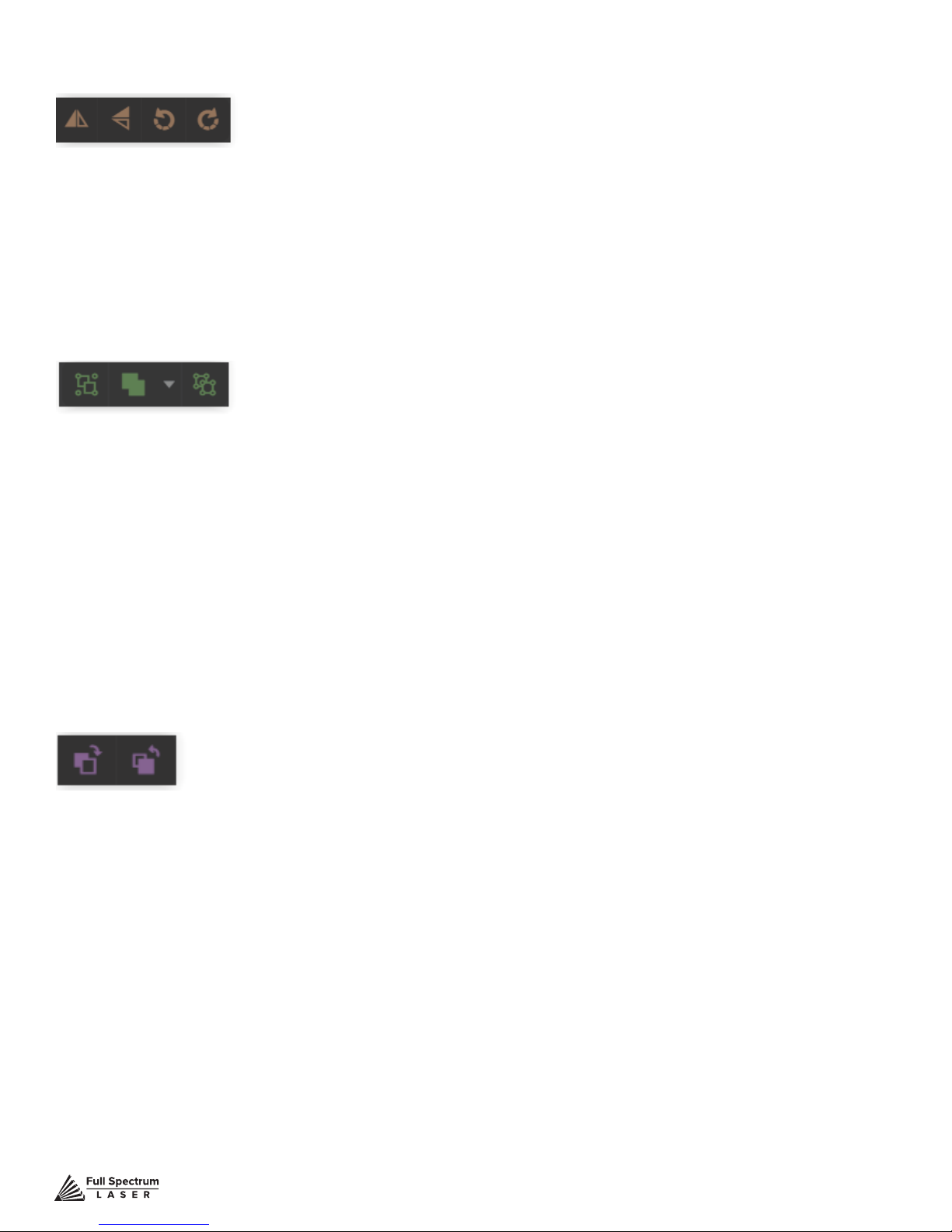
Position Menu
Flip Horizontally: Flip object along horizontal axis.
Flip Vertically: Flip object along vertical axis.
Rotate 90° Left: Rotate object 90° left.
Rotate 90° Right: Rotate object 90° right.
Group Menu
Group: Group objects
Merge
Union: Combine layers into a single compound layer.
Difference: Combine non-overlapping layers into a single compound layer.
Intersection: Combine overlapping layers into a single compound layer.
Subtract: Remove and combine non-overlapping layers into a
single compound layer.
Split: Split up a compound shape or object.
Arrange Menu
Bring Forward: Send an object one layer forward.
Send Backward: Send an object one layer backward.
Technical Support is available from 8am to 5pm (PST) M - F at [email protected].
57
Page 59
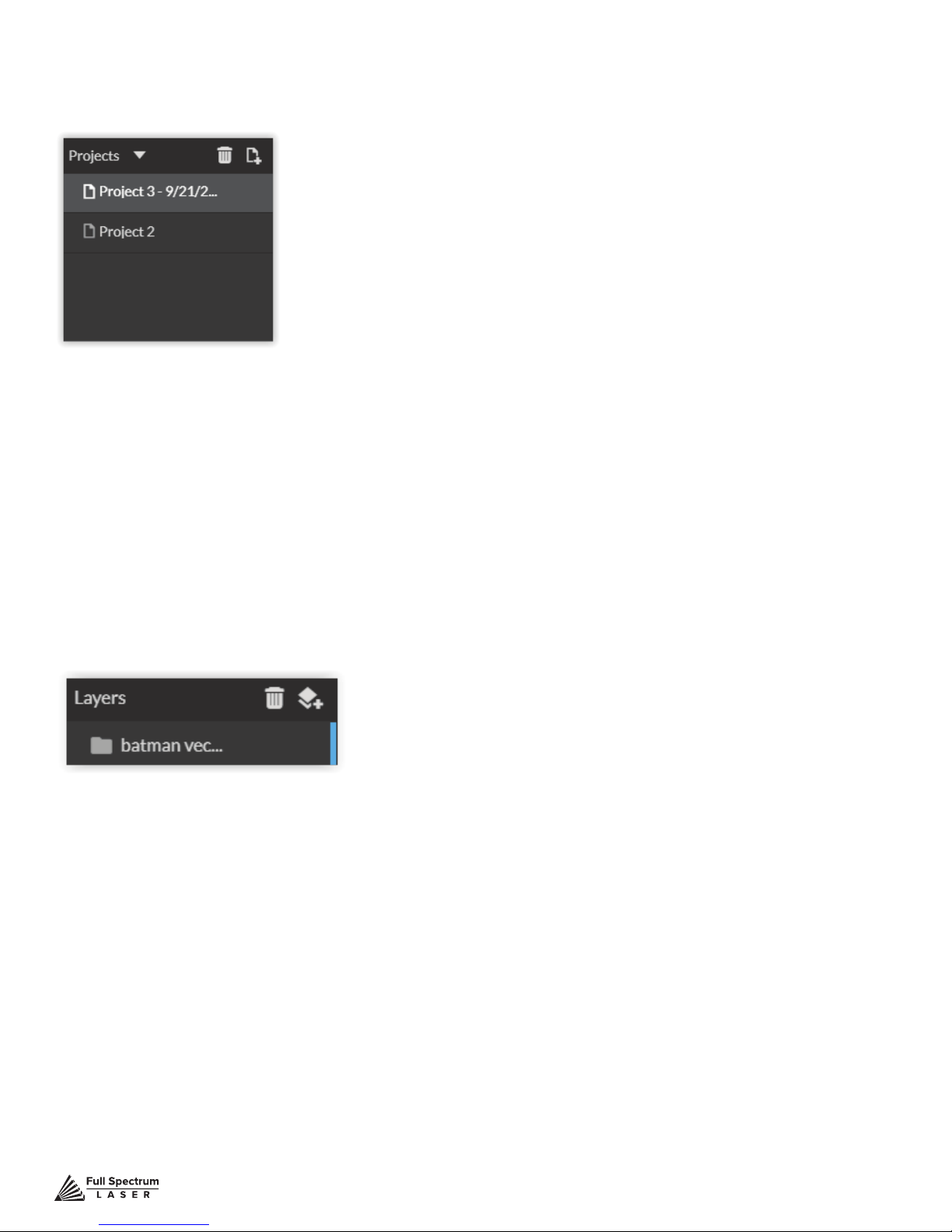
Projects Menu
Displays information about projects.
Reduce Window: Reduce or expand projects window.
Delete: Delete selected project.
Create New Project: Begin a new project.
Project Name: Displays project’s name.
Toggle Lock: Lock or unlock project in current order.
Toggle Visibility: Turn visibility of project on or off.
Layers Menu
Displays information on layers.
Delete: Delete selected layer.
New Layer: Add a new layer.
Layer Name: Displays name of project.
Toggle Lock: Lock or unlock layer in current order.
Toggle Visibility: Turn visibility of layer on or off.
Toggle Outline: Turn displayed outline of layer on or off.
Technical Support is available from 8am to 5pm (PST) M - F at [email protected].
58
Page 60
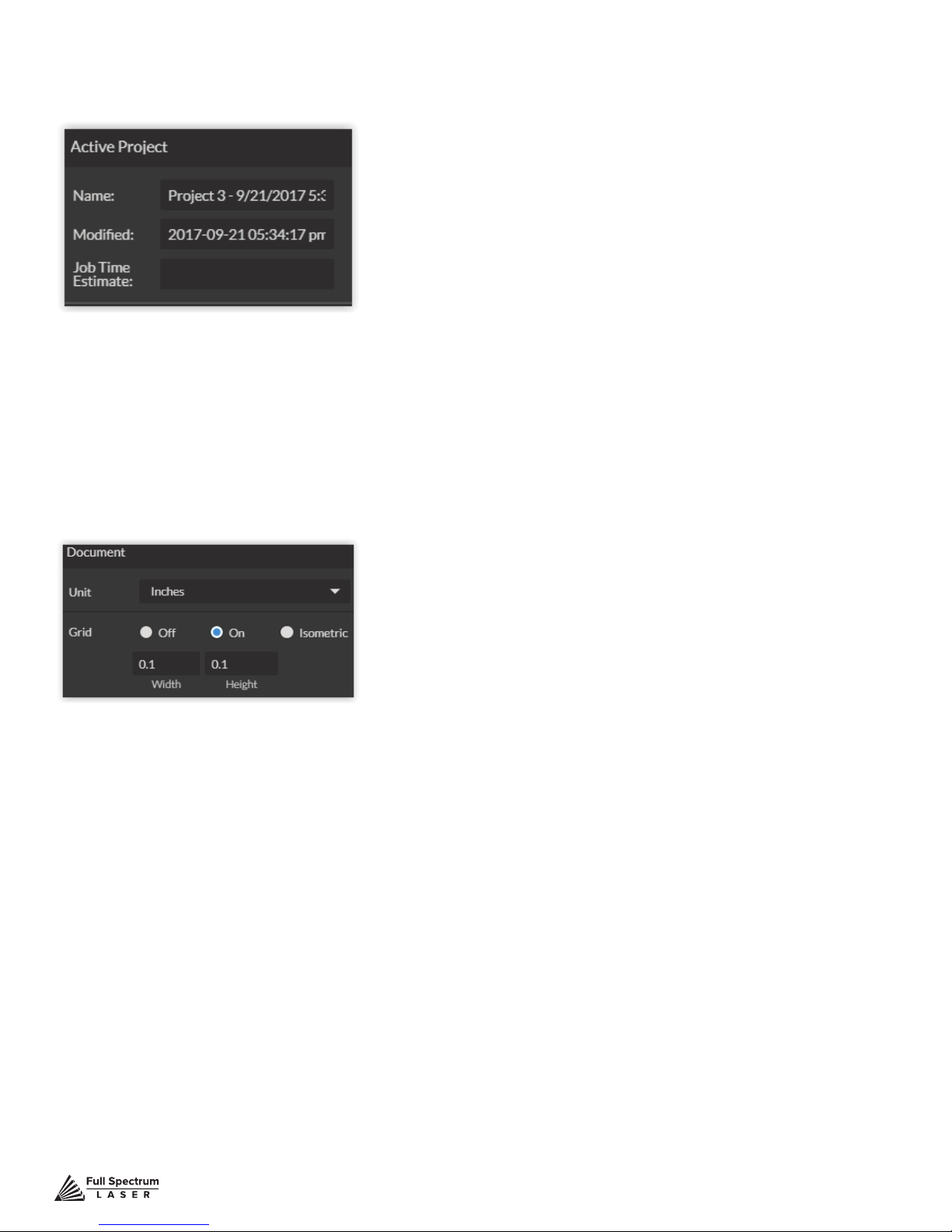
Active Window Info.
This window displays information regarding the active project.
Active Project Name: Displays name of active project.
Modied: Displays last date project was modied.
Job Time Estimate: Displays estimated time until job is complete.
Document Window
Unit: Choose unit of measurement from the following -
Pixels: Sets unit of measurement to pixels.
Centimeters: Sets unit of measurement to centimeters.
Millimeters: Sets unit of measurement to millimeters.
Inches: Sets unit of measurement to inches.
Picas: Sets unit of measurement to picas.
Points: Sets unit of measurement to points.
Grid: Toggles grid on/off/isometric.
On: When “on” grid displays in workspace.
Off: When off, grid does not display in workspace.
Isometric: Toggles grid from squares to isometric grid.
Width: Displays width of item according to chosen unit of measurement.
Height: Displays height of item according to chosen unit of measurement.
Technical Support is available from 8am to 5pm (PST) M - F at [email protected].
59
Page 61
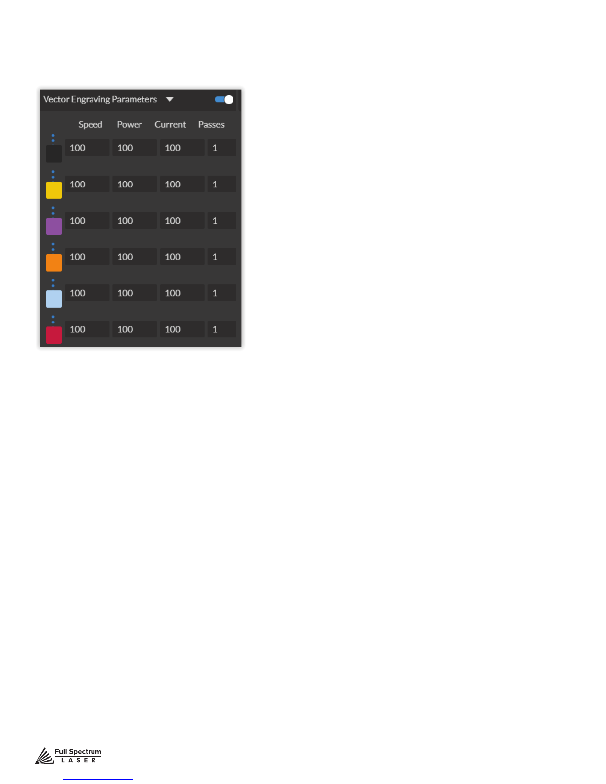
Vector Engraving Parameters Window
Window appears when vector le is detected and is used to input vector settings.
Hide Window: Click to hide vector engraving parameters window.
Show All Parameters: Toggle to show or hide all parameters.
Change Position: Drag with mouse to reorder any color.
Color Indicator: Separates vector cuts with color indicators.
Speed: Input speed settings.
Power: Input power settings.
Current: Input current settings.
Passes: Input the number of passes for the laser.
Technical Support is available from 8am to 5pm (PST) M - F at [email protected].
60
Page 62
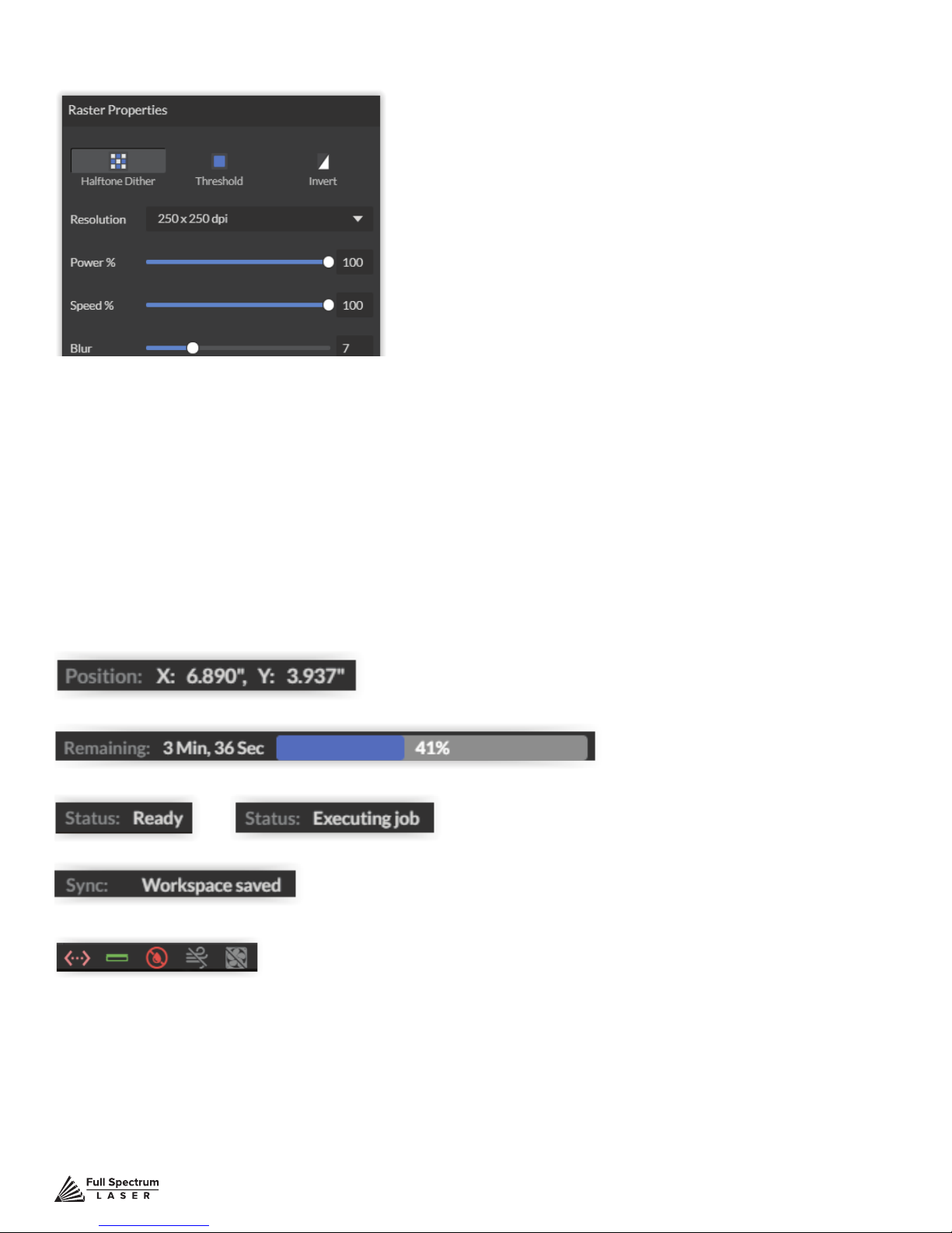
Raster Properties Window
Halftone Dither: Apply Halftone Dither.
Threshold: Apply Threshold.
Blur: Adjust blur lter radius from 0 to 30.
Edge: Adjust edge enhancement threshold from 0 to 30.
Intensity: Adjust intensity from -255 to 255.
Invert: Reverse Black and White elements.
Resolution: Set resolution (250, 500, 1000 dpi).
Poser %: Select power percentage from 1 to 100.
Speed%: Select speed percentage from 1 to 100.
B/W Threshold: Select black and white threshold from 0 to 255.
Indicators (Bottom Row)
Position Indicator: Displays current position of the laser on the grid.
Time Remaining Indicator: Displays the time remaining to complete the current job
Status Indicator: Displays whether laser is ready to initiate a job or is currently executing a job.
Sync Indicator:
Machine Indicators: Displays information on connected devices.
Device Connection Available:
Lid Indicator: Tells operator if lid is open or closed. The laser will not re if lid is open.
Water Flow Indicator: Tells operator if water is owing through the laser tube or not. The laser will
not re if water is not running through the laser tube.
Air Assist Indicator:
running a job.
Exhaust Indicator: Tells operator if lid is open or closed. The laser will not re if lid is open.
ells operator if air assist is on or off. Air assist should always be on when
Technical Support is available from 8am to 5pm (PST) M - F at [email protected].
61
Page 63

SECTION VII. OPERATIONS
This section will guide you through using your Muse laser cutter. To get started, it is important to
understand the meanings of “Vector Cutting” and “Raster Engraving” and their associated le types.
VECTOR
Project Examples
Signs, Logos, Parts, Gears
File Types
PDF, SVG
Preferred File Type
PDF
File Composition
Geometric Formulas
RASTER
Image Engraving, Surface Marking
JPEG, GIF, PNG, TIF
JPEG
Pixels
Figure 7.1
General Functions
Vector Cutting
Vector cutting is the most common feature of a laser cutter. Vector cutting with a laser means “to cut a
line or shape”. When vector cutting, the laser follows the “vector lines” embedding in the vector image
to cut out the design. The laser starts at a designated location and follows the vector lines until the
shape is cut out. This process is highly accurate and requires no resolution adjustments because of
the properties of a vector image.
Vector Images
In Vector Cut mode, the software receives information from the print stream and interprets it as a
series of paths for the laser head to follow. For the print stream to have vector information, the le
being printed must be a vector image. Vector images are more exible than raster images. These
images are created using mathematical equations rather than pixel blocks. PDF’s work great as
vector les and are easy to resize without losing resolution. Company logos and branded graphics
are usually vector images.
Engraving
Engraving is the process by which complex designs are etched into a workpiece. Engraving
can range from a simple surface mark all the way through deep material removal. Engraving is
differentiated from cutting in that cutting is the process of burning a closed contour completely
through a workpiece. Engraving is also known as “Raster Engraving” or “Rastering”. For engraving,
a laser has two states: on and off. Every black pixel or “laser dot” is the result of the laser turning on
and ring at that location. This location is controlled by the input image, which can be thought of as a
Technical Support is available from 8am to 5pm (PST) M - F at [email protected].
62
Page 64

“map” of on and off pixels. The laser res individual pulses corresponding to pixels in an image. When
the laser is operating in raster mode the head moves rapidly from left to right and slowly from top to
bottom, engraving your image pixel by pixel and line by line.
Images and Engraving
Engravable images use multiple colored pixels to form an image. JPEGs and PNGs are common
engraving image types. Most of the photos found on the Internet and photo prints are raster images.
Raster images are created using a xed number of colored pixels, so they can’t be dramatically
resized without distorting their resolution. When sized to ft a space they weren’t designed to,
the pixels become visibly grainy and the image becomes distorted. When this happens, altered
photos may appear pixelated or low resolution compared to the original source. Because of this,
it is important that you save raster les at precisely the dimensions needed to eliminate possible
resolution issues.
PDF Files
Engraving works with both vector and pixel-based source les, allowing you to engrave anything from
a simple block logo all the way to high-resolution photographs. A PDF le type is generally treated
as vector le, however, RetinaEngrave 3.0 can read PDF les as either a vector or an engraving le
when you import the image. This allows operator great freedom in converting any image le to a PDF.
Direct Printing PDF Files
The easiest way to import any le type to RetinaEngrave 3.0 is to “drag ‘n drop” it directly into the
workspace window. If there are ever any problems importing les in this manner, direct printing
a converted PDF le is the next method to try. Most design software have a simple method for
converting les to PDF and then directly printing them to the RetinaEngrave 3.0 software.
Designing in RetinaEngrave 3.0
RetinaEngrave 3.0 includes a robust set of design tools, allowing users to design in the software
without needing outside design software. Third party design software, however, is still an option for
RetinaEngrave 3.0 users. Just about any design software will work (You can choose the software you
are most comfortable with, as long as you can convert les to PDF (which most can). You can also
“direct print” to the software. Each operating system does this in a slightly different way, so check the
instructions for your particular program.
If you use third party design software and run into a problem with the print interface, we recommend
printing to the XPS Document Image Writer or saving as a PDF. PDF les save vector information and
are the best way to carry artwork from a non-compatible operating system (Mac or Linux) onto your
Windows PC.
Compatible design packages include: CorelDraw, Adobe Illustrator, Inkscape and Google’s free online
vector drawing application. Additionally, most CAD packages are able to output drawings in a vector
format for printing; Autodesk 123D is particularly interesting for its cost (free) and built-in 3D slicing
capabilities.
Technical Support is available from 8am to 5pm (PST) M - F at [email protected].
63
Page 65
Using Your Muse Laser Cutter
Project Workow
The RetinaEngrave 3.0 software works with your Muse to create a simple and intuitive set of
operations that is easy to learn and use. With experience, you will nd your Muse achieving amazing
results following this procedure. Use this Project Workow List for the “best practice” sequence for
any project and follow the step-by-step instructions from start to nish.
1. Create Design:
Create your design in the program of
your choice. Note: Files should be
created with laser cutting considered.
4. Place Material:
Place your material into the laser
bed workspace.
7. Adjust Object Properties:
Using the Properties Manager Window,
adjust your Vector or Raster settings for
your cut, mark or engraving.
2. Connect to Software:
Link your Muse to the software by typing
the IP address found on the Touch Screen
(Settings>Network>Copy IP) into your
browser (Google Chrome Suggested).
5. Focus:
Using the included focus billet, focus
the laser to the material (consult your
user manual). Note that if your Muse
has the autofocus feature, focusing is
automatic when the job is run.
8. Run Job:
Double check your safety precautions
and accessories, and press the “play”
button to start the job.
3. Import Design:
Using direct print from your design
program, or by drag-n-dropping
the le into the RetinaEngrave 3.0
workspace, import your design to
the software.
6. Align Laser to Material:
Using either the perimeter tool, or
camera function (see camera features),
align your design on the appropriate
area of your material.
Technical Support is available from 8am to 5pm (PST) M - F at [email protected].
64
Page 66
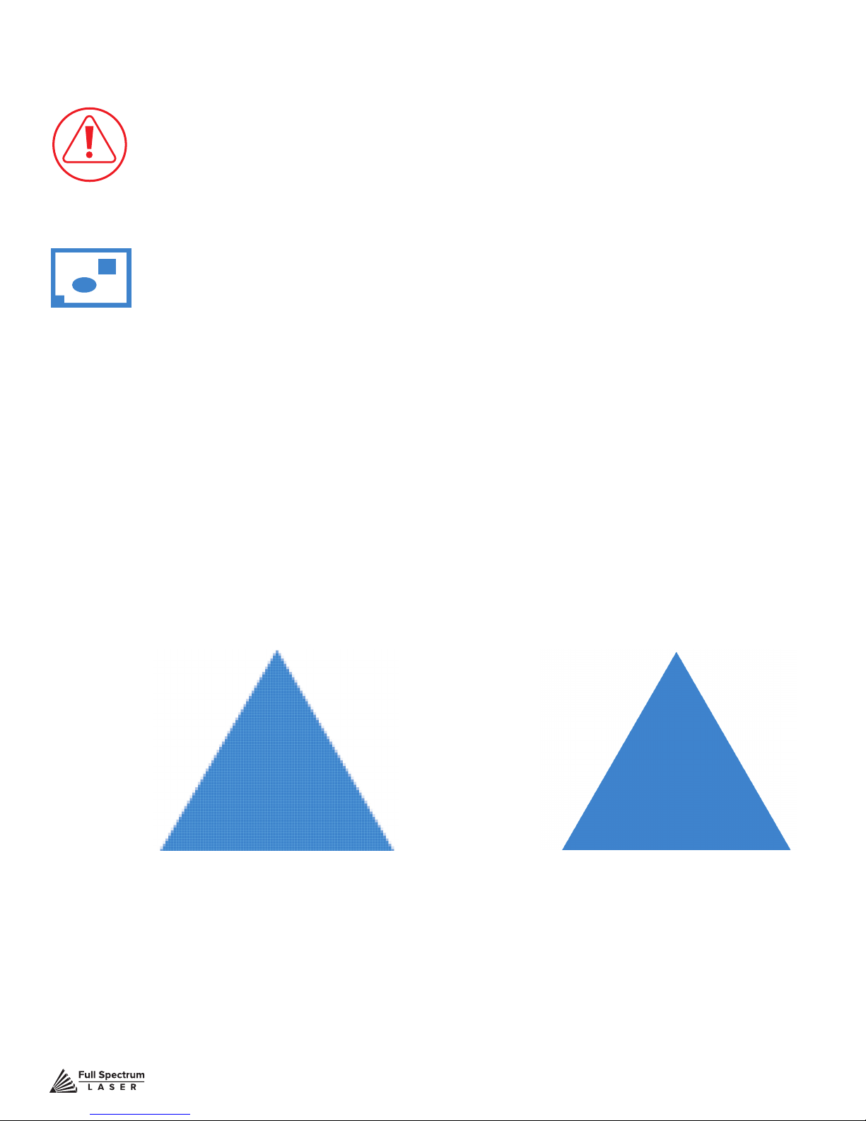
Project Workow Checklist
Safety First
Before starting any project, be sure you are aware of all safety issues. Be sure you
read and understand all safety warnings presented in Section I: Safety First and
that all safety requirements are being upheld. This is a good time to check your
machine’s power connections and that the accessories are properly attached and are
operating normally.
1. Create Design
Typically, projects are created in design software and then imported to RetinaEngrave
3.0. Generally, a PDF le is optimal for most vector cuts, as PDF les are easy to
convert to and most design software has “convert to PDF” as a standard feature. For
rastering (engraving), a JPEG le is best as these are bitmap les perfect for pixel
based images. It is important to know, at this stage, if you intend to do a vector cut
or an engraving and choose the most appropriate le type (PDF or JPEG). This will
greatly aid the software to run the job smoothly and quickly. RetinaEngrave 3.0 includes
a robust set of design tools, allowing users to design in the software without needing
outside design software. Third party design software, however, is still an option for
RetinaEngrave 3.0 users. Just about any design software will work (You can choose the
software you are most comfortable with, as long as you can convert les to PDF (which
most can). You can also “direct print” to the software. Each operating system does this
in a slightly different way, so check the instructions for your particular computer..
Figure 7.2
Raster Image (bitmap)
Pixel based image.
Example: JPEG
Vector File
Geometric based
image. Example: PDF
Technical Support is available from 8am to 5pm (PST) M - F at [email protected].
65
Page 67

2. Connect to Software RetinaEngrave 3.0
Follow the instructions presented in Section III: Installation & Assembly. As a recap, you
will turn on your computer and your Muse laser cutter and wait for both to nish their
boot cycle. Then, observe the connected network address on the lower left corner of
the Muse LCD. Copy this IP address into your computer’s browser navigation bar and
the program will appear, ready to use. For best results, we recommend using Google
Chrome as this is the most compatible with RetinaEngrave 3.0 technology. Note that
your PC and your Muse unit must be connected to the same network at all times during
normal operation.
3. Import Design
Import your designs by selecting the “Open File” icon, or by dragging and dropping your
le into the workspace. This software detects a wide variety of le types, however, for
vector cuts PDF les work best and are simple to convert on most design software. For
raster engraving, the JPEG le format is widely used and can easily be taken from a cell
phone photo or an image found online. It is important to know what les work best with
vector or raster images. A raster image is a pixel based image (bitmap) and works well
as a JPEG le. When you import a JPEG le, the software will automatically detect it
as a raster le and will setup the project accordingly by presented raster options in the
properties tab menu.
4. Place Material
At this stage you will place your material into the laser bed workspace. The material
can be placed anywhere within the workbed, however, we recommend placing material
close to center. Once the material is placed, close the lid. Your material is what you will
be cutting or engraving. Typical materials include wood, acrylic, cardboard, fabric, etc.
Note that is the user’s responsibility to know the components of any material used and
the limitations of utilizing that material (thickness, chemical residues, etc.) with a 45W
laser tube. Always check with the material manufacturer, or MSDSonline.com, if there
are any questions to its usage. We recommend using a Materials Log to keep track of
the different materials you use.
5. Focus
Follow the Focusing instructions given in Section IV: Tests & Adjustments. Just to recap,
you will place focusing billet on top of the material you wish to cut. Then align the laser
head to the focus billet and release the focus lens thumb screw and allow the laser head
to rest lightly on top of the focus billet. Finally, retighten the focus head and remove the
focus billet from the workspace. Note that if your Muse has the autofocus feature, focusing is automatic when the job is run.
6. Align Laser to Material
Alignment of the material ensures the design to be cut is contained within the material
in the workspace. This process also makes sure the design is aligned to the material so
the cut is positioned straight. Typically this can be done with a simple vision check while
“jogging the perimeter”.
By using the directional arrows on the touchscreen or the arrow keys on your computer,
Technical Support is available from 8am to 5pm (PST) M - F at [email protected].
66
Page 68

move the laser dot to the top left corner of your material. When placing an engraving
image, leave at least ½” inch of space on the left and right side. When creating engravings, you must compensate for the left and right overshooting of the laser head. Once
the material looks aligned, click the “Jog Perimeter” button. The laser head will automatically outline the material with the red beam diode. You can then adjust the material as
needed. Note the laser head will continue to outline the material until stopped manually
by clicking the “Run Perimeter” button a second time. See Positioning below for more
options.
7. Adjust Object Properties
It is again important to know if you intend to raster, vector cut or both. Once the le is
imported, and the image is clicked with your mouse, you will have access to the Properties Tab. Click this tab and select the parameters for your cuts and/or engravings. For
details on setting these parameters, see below.
8. Run Job
Clicking the “Start Job/Play” button begins the laser cutting process. Before doing so,
double check your safety protocol and that your system accessories are connected
properly. Be sure to monitor the job while the laser is ring. If there is a problem, stop
the laser using one of the methods mentioned below.
Technical Support is available from 8am to 5pm (PST) M - F at [email protected].
67
Page 69
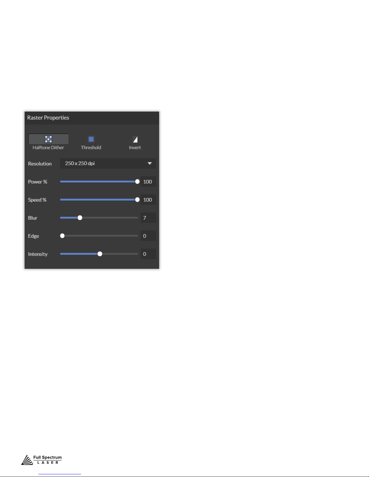
Engraving
Engraving, also called Rastering, is the process of creating a surface image on material without cutting through the material entirely (aka vector cutting).
Setting Engraving Properties
Clicking an object (design image) in the workspace will allow you to access that object properties tab.
The software will identify if the object is a vector or an engravable object and present the appropriate
properties window. To show the properties of an engravable object, click the object.
Setting Resolution
The resolution of your engravings can be controlled by the DPI (Dots Per Inch). DPI options include
250, 500, and 1000. The more dots per inch, the higher precision and quality of your images, while a
lower DPI will process and engrave faster.
Remember that with a higher DPI (1000), the laser is in contact with the material for a longer period
of time and may result in deeper engravings than with a lower DPI (250). Speed and power should be
compensated for different DPI settings. The software’s default resolution is set to 250 DPI.
Setting Raster Power
The power settings determine the output of the laser tube. A 100% power setting will create
a deeper engraving while lower settings will create more surface level engravings.
Setting Raster Speed
Speed settings determine how quickly the laser head will move. For faster engravings,
100% is ideal. Lowering the speed will allow you to create deeper engravings, as it allows the laser
beam to be in contact with the material for a longer period of time.
Technical Support is available from 8am to 5pm (PST) M - F at [email protected].
68
Page 70
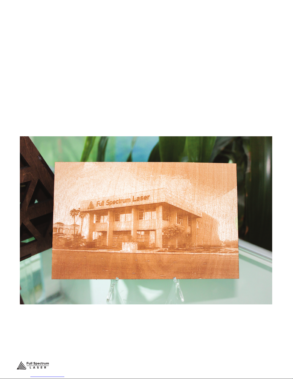
Applying B/W Threshold
At this moment, the image is still displayed in black and white. The black and white raster feature is
great for tracing logos, text, or simple high contrast images that only appear in a single color. You can
adjust the threshold of what’s considered black, and what’s considered white by selecting your image
and clicking “Threshold”. This will bring up a B/W Threshold slide bar, from which you can adjust B/W
threshold to your liking.
3D Engraving Options
For images that have shadows and depth, it’s ideal to use 3D engraving. 3D engraving creates a
series of dots similar to newsprint. This effectively creates a grayscale that is ideal for photorealistic
engravings. To 3D egrave an object, click the 3D engraving button. You can then adjust the 3D
engraving with the Blur, Edge and Intensity slide bars.
PHOTO ENGRAVING EXAMPLE
Technical Support is available from 8am to 5pm (PST) M - F at [email protected].
69
Page 71
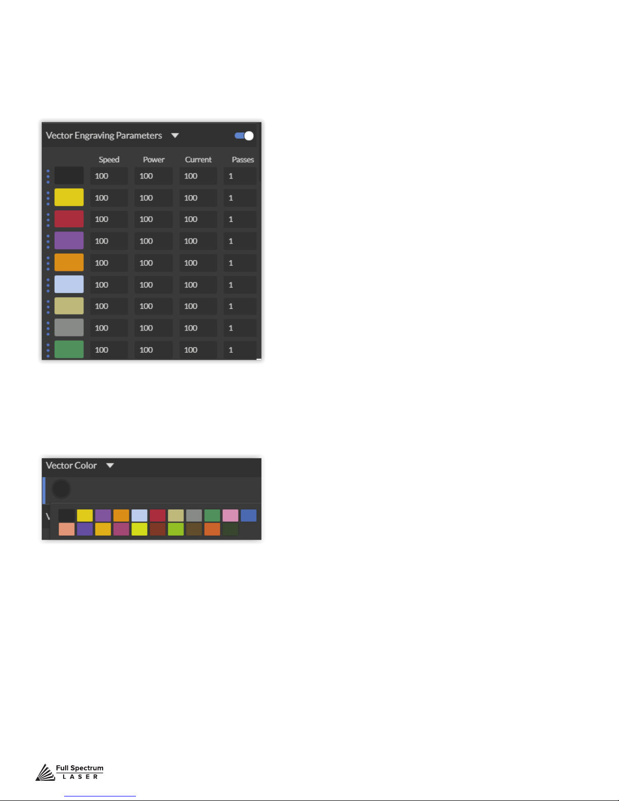
Vector Cutting
Setting Vector Properties
When a PDF le is imported into RetinaEngrave 3.0, the program automatically detects it as both a
vector le and a raster le.
Vector Color
Tags allow you to create separate vector layers and keep track of them with a unique color. Each
color will match an object in the workscreen. You can set the order of operations by clicking on the
“three dots” and then dragging the layer up or down. Objects are then processed from top to bottom.
Setting Vector Power
Power will determine how much power the laser tube delivers. As with speed, power will vary
depending on the wattage of the laser tube and the material itself. You will need to experiment with
material testing to nd the right speed for your vector cuts.
Setting Vector Current
Vector current is a control unique to vector les. Vector current controls the pulse of the laser. 100%
will create constant power for smooth cutting, while lower percentages will add increasingly more off
time between pulses. As always, settings will vary with your tube wattage and type of material. It’s
best to test on an inconspicuous part of your material before creating your nal piece. Once optimal
results are discovered for speed, power and current, through material testing, record the settings for
each in a materials log.
Technical Support is available from 8am to 5pm (PST) M - F at [email protected].
70
Page 72
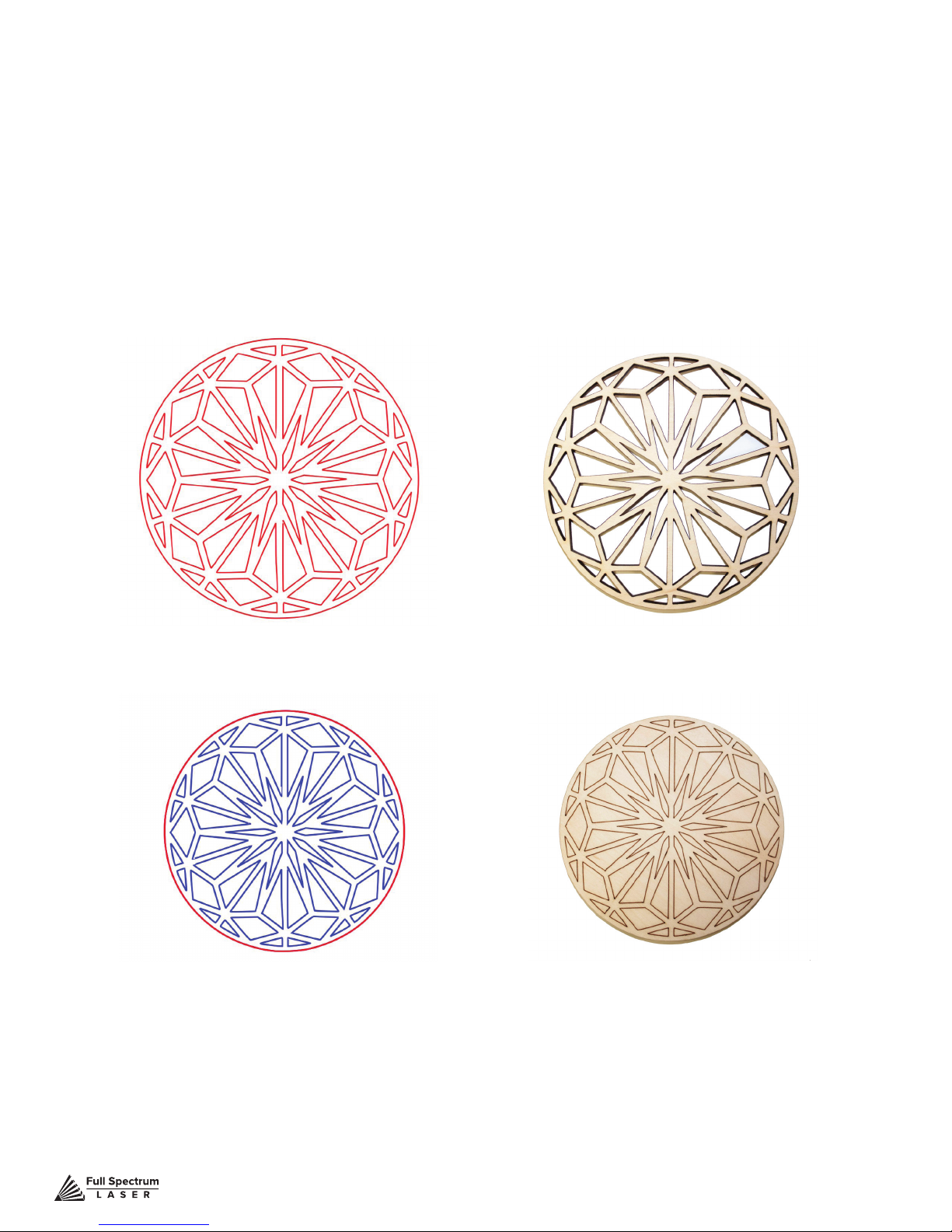
Passes
This allows the operator to assign how many times the laser will complete a full cycle. Adding passes
creates deeper cuts. Note that if you delete a vector line (by clicking “-“), set passes to “0” rst.
Show All Parameters
This toggle switch displays or hides all possible vector tag as a series of color options. Often
when performing both vector cuts and raster engraving, it is a good idea to change the color of the
vector cut to something other than black. This will avoid the laser detecting the vector cut as part
of the raster.
Basic Vector Cutting Example
Vector Marking Example
We can outline (as opposed to ll) parts of the pattern for a second design option. Again, we will
instruct the laser using our vector properties In this design, the blue lines will not be cut through on
our material, but instead will be marked, as the red outline still cuts.
Technical Support is available from 8am to 5pm (PST) M - F at [email protected].
71
Page 73
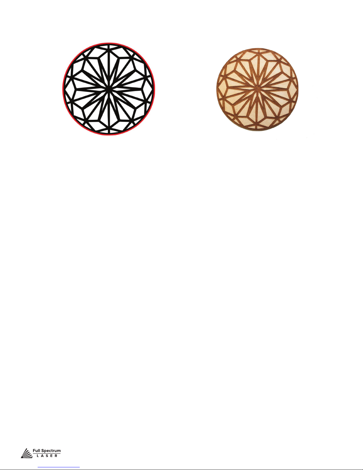
Combining Vector and Raster
Engravings can be combined with vector cuts to create a variety of outcomes. A simple example is to
engrave an image, and then cut the image out with a vector outline. In this case the laser will raster in
the black l and cut the red line.
Technical Support is available from 8am to 5pm (PST) M - F at [email protected].
72
Page 74
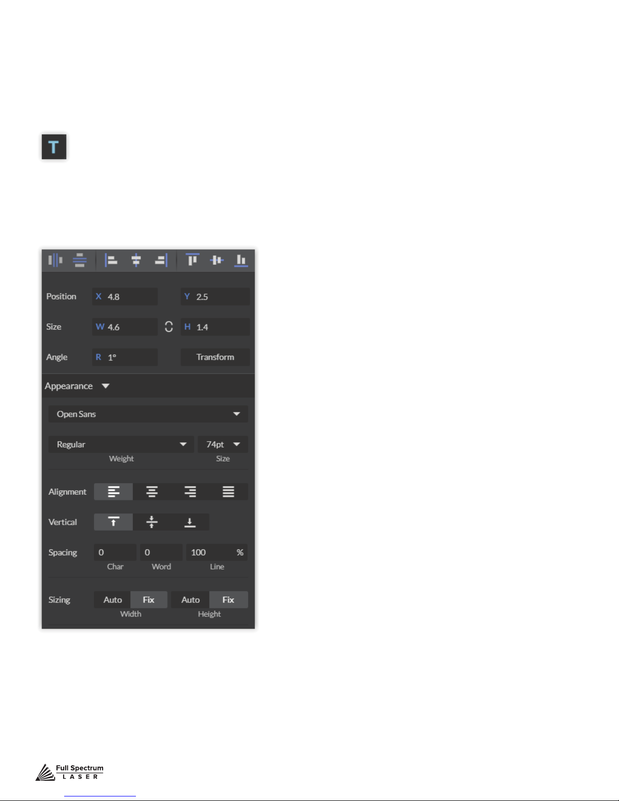
Designing With RetinaEngrave 3
RetinaEngrave 3.0 contains design tools to allow for custom designs within the software itself. Here
you can design and create objects without accessing third-party design software.
Adding Text
Click the “T” icon and then click anywhere in the view window. You can now write your text. To customize your text, click on the text object you created and a new window will appear with options to
adjust the positioning, size and font of your text.
Full Text Options Window
Technical Support is available from 8am to 5pm (PST) M - F at [email protected].
73
Page 75
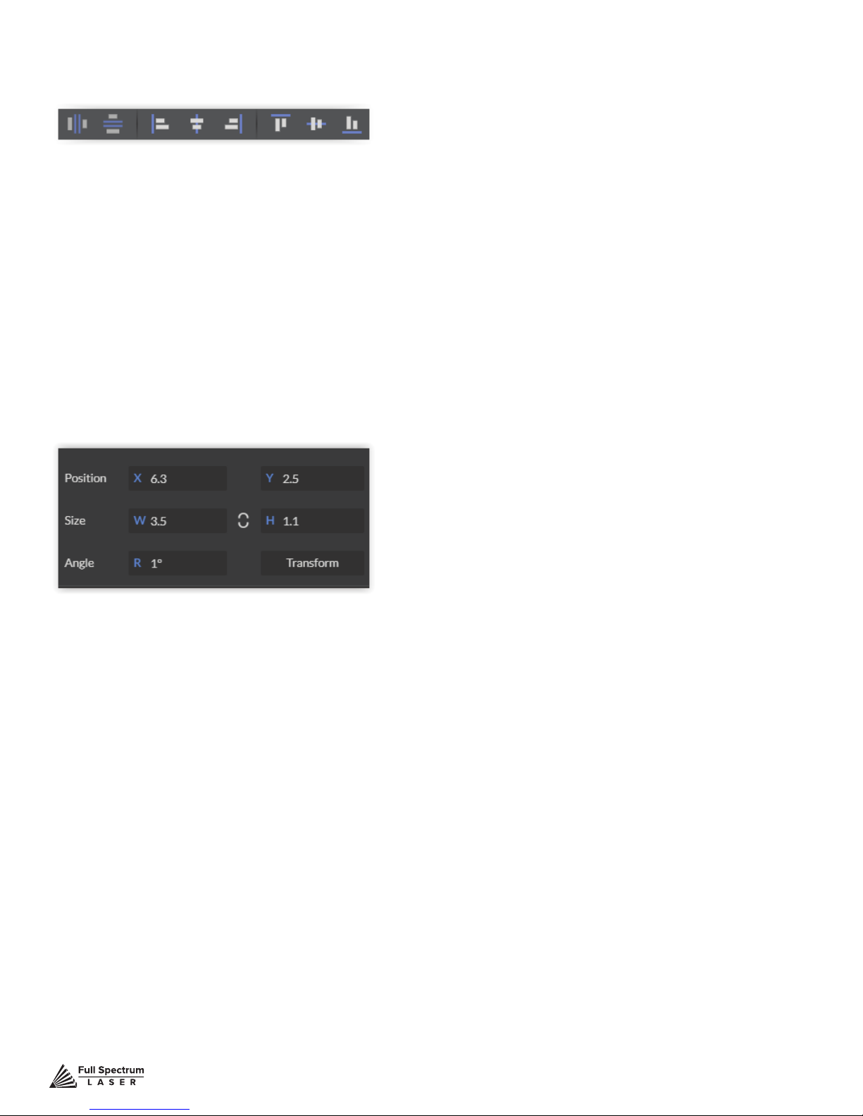
Text Positioning
Text position can be quickly adjusted by clicking on one of the following options.
Distribute Horizontally: Evenly arrange selected Text horizontally.
Distribute Vertically: Evenly arrange selected text vertically.
Align Left: Align text to the left.
Align Center: Align text to center.
Align Right: Align text to right.
Align Top: Align text to top.
Align Middle: Align text to middle.
Align Bottom: Align text to bottom.
Text Positioning Coordinates
This window displays the coordinates and other specs of the selected text. Coordinates can be
changed manually by entering the desired specics directly into the software.
Position: Displays position of text in X/Y coordinates in the workspace. Click box to directly input X/Y
coordinates.
Size: Displays size of text according to width and height. Click box to directly input desired width and
height of text.
Angle: Displays angle of text as a degree. Click box to directly input angle degree of text.
Transform: Clicking the transform button brings up the Transform Window options.
Technical Support is available from 8am to 5pm (PST) M - F at [email protected].
74
Page 76
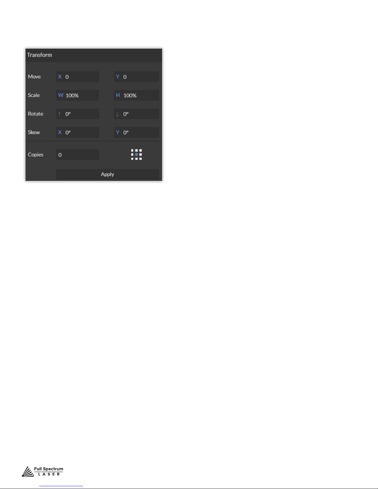
Text Transform Options
Transform options allow the operator to alter the shape and skew of text.
Move: Set X/Y coordinates.
Scale: Manipulate the scale of text, separately, in width and height.
Rotate: Rotate text a set number of degrees, up or down.
Skew: Skew the angle of text by a set number of degrees on the X and Y axis.
Copies: Create duplicates of the selected text.
Apply: Click to apply all transform changes.
Technical Support is available from 8am to 5pm (PST) M - F at [email protected].
75
Page 77
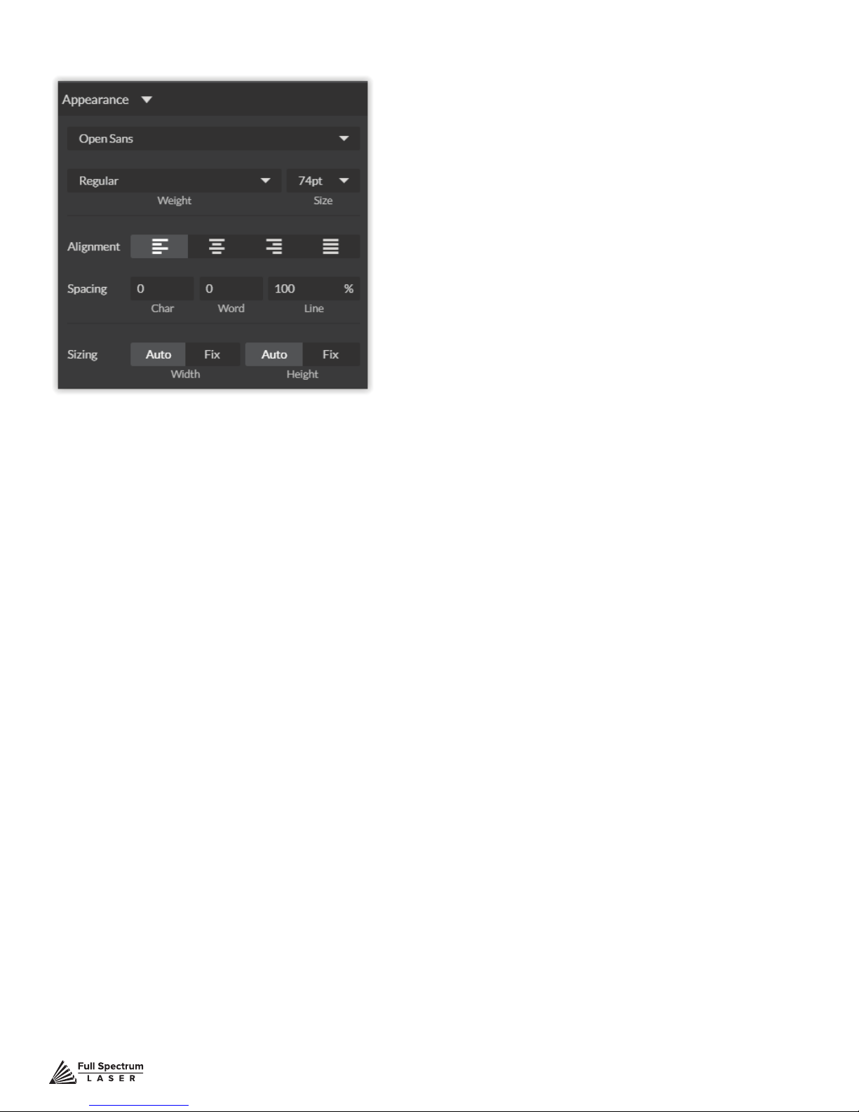
Text Appearance
Select Font: Choose or change selected text font.
Weight: Choose bold and italic options for selected text.
Font Size: Choose font size for selected text.
Alignment: Align or justify selected text left, right or center.
Spacing: Set pacing or characters, word blocks and line spacing.
Sizing: Lock all sizing options (Fixed) or allow custom alterations (Auto). When set to auto, click on
text and use mouse to manipulate corner nods to change size.
Text Path Options
Attach Text to Path
This function allows the user to attach text to a shape and contour the text to that shape. As an example, user creates an ellipse design and a text element separately. With the mouse, drag a square
over both. By clicking Attach Text to Path, the text is merged with the ellipse and the text conforms to the contour of the shape. The user can then drag the text element to the desired position,
using the mouse.
Detach Text from Path
This function reverses the Attach Text to Path option. Select the object and text with the mouse by
dragging a square to highlight both. Then, click Detach Text from Path. The shape and the text will
now be separated.
Convert to Path ( Shift+Ctrl+P)
Convert a non path to a layer path. If a layer is composed of elements that are treated like
paths, internally, or the layer is a Text object, the existing paths that make up the object are
simply extracted from the object as they are already dened. The result is a compound path
containing all of the separate paths. Any transform information from the original layer is not
retained in the individual paths. For all other types of layers a new path is created, preserving
any transforms. The user creates a text layer then converts to a path. Because the text was
comprised of more than one distinct element a compound path is created. The compound
path can then be split into separate paths for each distinct element in the text.
Technical Support is available from 8am to 5pm (PST) M - F at [email protected].
76
Page 78
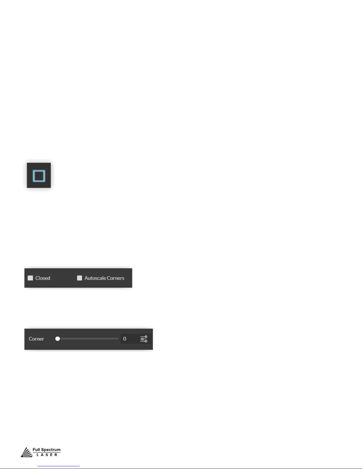
Convert to Raw Path
Convert a path or non path layer to a new path. This is similar to Convert to Path with some important
differences. With Convert to Raw Path new path objects are always created regardless of the type of
the original layer and transforms are preserved. The user creates a text layer then attaches it to an
ellipse path so that it follows the curvature of the ellipse, then converts the text to a raw path. The text
retains its curvature because the transforms of the separate text paths are preserved.
Creating Objects In Retinaengrave 3
The easiest way to create an object is to select a shape from the tools menu. For example, you want
to make a circle. Select the circle tool, then click and drag to create a circular shape. By holding shift
while dragging, you can constrain the proportions so that the circle is perfectly round. Design view
has hundreds of shapes that can be selected and manipulated to endless choices. Click the “Star”
icon to access shape library.
Creating Shapes
Click the Square Icon and then click and hold anywhere in the view window. By moving the mouse,
you can expand and manipulate the square you want to create. By clicking the drop down arrow next
to the Square Icon, you can choose other base shapes and expand them just like with a square. The
basic shape library includes line, rectangle, ellipse, polygon, triangle and star. You can modify any
shape by clicking on it and then adjusting the interface data appearing on the right side of the screen.
Each shape will have slightly different options as follows:
Line (L)
Closed:
Autoscale Corners:
Rectangle (R)
Round: Create rounded corners.
Round2: Create inverted rounded corners.
Bevel: Create beveled corners.
Inset: Create inset corners.
Fancy: Create fancy corners
Autoscale Corners: Toggle autoscale corners on and off.
Uniform Corners: Click to ensure all corners have the same parameters.
Technical Support is available from 8am to 5pm (PST) M - F at [email protected].
77
Page 79
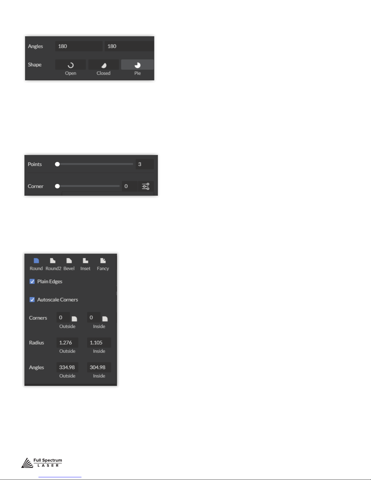
Ellipse (E)
Angles: Input custom angles
Shape
Open: Click for open ellipse.
Closed: Click for closed ellipse.
Pie: Click for pie shaped ellipse.
Triangle, Polygon & Star
Points:Slide bar to create polygons with multipoints (3 to 25).
Corner: Slide bar to curve corners
Advanced Settings: Clicking the icon opens a new popup window.
Advanced Settings
Technical Support is available from 8am to 5pm (PST) M - F at [email protected].
78
Page 80

Round: Create rounded corners.
Round2: Create inverted rounded corners.
Bevel: Create beveled corners.
Inset: Create inset corners.
Fancy: Create fancy corners
Autoscale Corners: Toggle autoscale corners on and off.
Uniform Corners: Click to ensure all corners have the same parameters.
Plain Edges:Toggle plain edges on and off.
Corners: Input outside and inside corner curvature.
Radius: Input outside and inside corner radius.
Angles: Input outside and inside corner angles.
Technical Support is available from 8am to 5pm (PST) M - F at [email protected].
79
Page 81

Creating and Manipulating Compound Shapes & Objects
Operators can combine and modify shapes and objects to create unique compound shapes and
objects with these functions (see also Modify):
Split Selection (Shift+Ctrl+G)
Split up a previously created compound shape or object that has been Unioned with other shapes.
Select the compound shape and choose Split Selection. The different objects are split back up into
individual layers that can be moved independently.
Create Compound Shape->Union
Combine multiple layers into a single compound layer. Union will create a compound shape containing all of the selected layers, retaining their relative positions. Union together several different object
and create a compound shape so they can all be moved and manipulated as one. To reverse,, select
the compound shape and choose Split Selection. The different objects are split back up into individual
layers so you can move one of them independently.
Create Compound Shape->Intersection
Combine overlapping layers into a single compound layer. Intersection will create a compound shape
containing the areas where the selected layers overlap. Intersect together part of an ellipse and part
of a rectangle to create a new compound shape with curved and straight lines.
Create Compound Shape->Subtract
Remove and combine non-overlapping layers into a single compound layer. Subtract will create a
compound shape containing only the areas of the last selected layer where the other selected layers do not overlap. For example, users can create an ellipse and subtract a rectangular area so the
ellipse can be placed over another layer and not obstruct part of it. Or use to make a design that is
made up of standard shapes by subtracting certain areas
Create Compound Shape->Difference
Combine non-overlapping layers into a single compound layer. Difference is the opposite of Intersection. It will create a compound shape containing only the areas where the layers do not overlap.
For example, the user can create a large circle ellipse, then create a smaller circle ellipse. Place the
smaller circle ellipse over the large circle ellipse and center it. Select both layers and choose Difference. A hole is created in the large circle ellipse and a donut design is formed.
Create Nested Compound
Combine compound shapes into a single compound shape. All of the selected compound shapes will
be nested within the compound shape that was selected last. For example, if user has created compound shapes and created the layout with the desired spacing but would like to move them all while
retaining the existing layout, creating a nested compound shape that includes them all works best.
Convert to Outline
Create an outline path of a specied size around an object. If the original object is not continuous,
such as a line, an outline is created around the line and the original line is replaced. If the original
object is continuous, such as a rectangle, an outline is created around the rectangle and the original
rectangle is preserved, resulting in a compound path with two rectangles. The user creates a curved
line then converts it to an outline of size 10. The result is a continuous curved polygon that looks like
a wet noodle.
Expand/Shrink
Scale an object up or down by a specied amount. The user creates an object and wants to grow it a
few pixels but trying to scale it with a selection box is too difcult. The user can expand the object by
specifying the exact amount.
Technical Support is available from 8am to 5pm (PST) M - F at [email protected].
80
Page 82

Creating & Converting Vector Paths
A vector path indicates the line the laser moves along while cutting. For a simple line, the path is a
clear route from Point A to Point B. More complicated paths, and shapes, can be created using the
following options in the Modify drop-down window:
Vectorize Border
Use to create a vector path of the border of an object. For example, the user creates an object, such
as a rectangle, and wants to have a vector path of just the border of the triangle.
Vectorize Image
Use to create vector paths of each separate element in an image. For example, the user rst imports
an image. User then wants certain parts of the image to be vectors so they can be cut. User vectorizes the image and then moves some of the resulting vectors out of the image object. The vectors can
then be edited.
Join Paths (Ctrl+J)
Combine 2 or more selected paths into one compound path. The result is a single layer titled ‘Compound Path’. It does not connect them into one continuous path but rather a single object with breaks
between the individual paths that were joined. The user joins together multiple path objects so that
they can be transformed more easily and change their properties as a single object.
Split Paths (Shift+Ctrl+J)
Split a compound path into its original separate paths.The result is a path layer for each separate path
in the Compound path.
Simplify Path (Ctrl+Alt+S)
Simplify (and smooth) a path to varying degrees of tolerance. The user creates a freehand line or
compound curve but the resulting curve has some sharp turns and jagged edges. Next, select the
path and simplies it with a tolerance (start with 20%). The resulting path has fewer vertices and
smoother turns.
Connect Path Lines
Connect together the ends of 2 or more paths. The user vectorizes an image containing text. Due to
the low quality of the image some, of the text characters have breaks in their paths, so the user selects the lonely paths and uses the “Connect Paths Lines” feature to connect the paths.
Break Curve
Break apart a path at a specied node. The user creates a path but would like to separate it and add
space at certain vertices to add another artistic element in between. Or maybe to specify different
engraving parameters for different parts of the path. To do so, the user selects a node and chooses
“Break Curve”. The path is separated into two separate paths.
Reverse Order
Reverse the order of nodes in a path. When the user creates several paths and uses the “Connect Paths Lines” feature, they are connected but not at the desired ends. This is because the
paths are connected from the last node of one path to the rst node of the next. Undo the previous
action and chooses “Reverse Order” on one of the paths. Then connects the paths and they are
connected perfectly.
Technical Support is available from 8am to 5pm (PST) M - F at [email protected].
81
Page 83

Positioning the Laser Head (Jog)
Operators will want to become accustomed to moving the laser head, in order to position the laser.
This can be done in one of two methods: manual and jog control. Manually moving the laser head
requires that the laser head be in the “Unlocked” position. To unlock the laser head, push the “Lock”
icon, on the touch screen, so that the icon has an open lock icon. The laser head can now be freely
moved to any position in the workspace by hand.
Jogging is when the operator uses the touch screen “jog” buttons, or Ctrl + Left Mouse Button within
the web application workspace, to move the laser head. To use the jog feature, the laser head must
be in the “Locked” position. To lock the laser head, push the “Lock” icon so that the icon has a closed
lock icon.
Positioning Material
Relative positioning is relative to the laser head. The red dot from the laser will be considered the top
left corner of an image. This makes positioning easier without the use of the Muse camera system.
Absolute positioning is the default mode and will directly translate the object’s location on the computer workspace to the respective location on the laser bed. Absolute positioning is ideal when using the
camera system.
You can switch from Relative Positioning to Absolute Positioning by going to Settings, within the Edit
drop-down options. Click Settings>Device. Next, choose Absolute Positioning or Relative Positioning
on the slide bar across from Laser Positioning. Click Save Changes when you are done.
Technical Support is available from 8am to 5pm (PST) M - F at [email protected].
82
Page 84
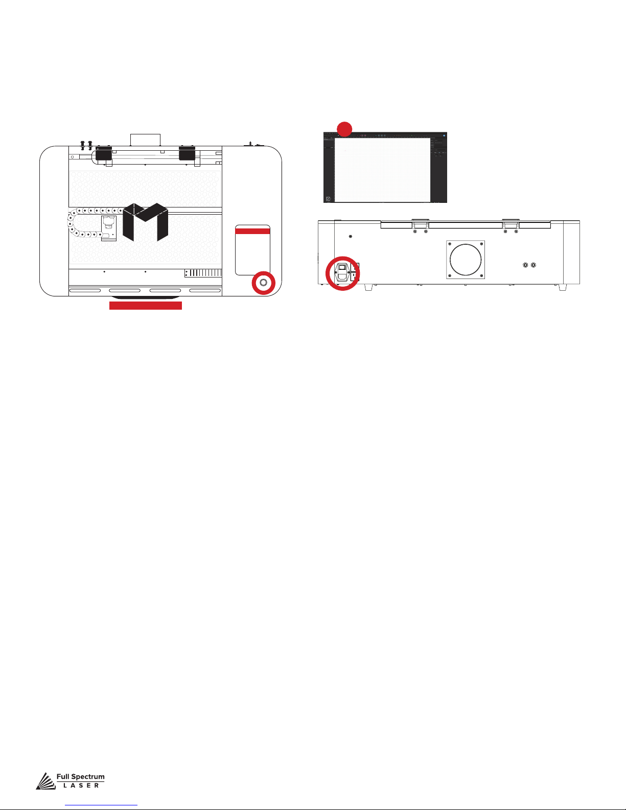
Stopping the Laser
Once a project has begun, the laser will continue until the project is complete. If for any reason an
operator needs to stop the laser immediately, choose one of these options:
Figure 7.4
4
3
5
2
6
1
1. Open the Lid. The large workbed access lid is installed with a device that automatically (and in-
stantly) cuts off the laser if it is opened even slightly. This should be your rst method of stopping the
laser during an emergency. This is a safety feature of Muse and under no circumstances should this
safe lid auto-shutoff device be tampered with or removed. Doing so will void your machine’s warranty.
If the machine ever fails to shut off the laser when the safety lid is open, immediately unplug the machine and contact customer service.
2. Touch Screen Pause Button. Top of Machine Pause Button. On the top of Muse machines there
is a button that can pause or stop the laser. Press once to pause the job. Press and hold to stop the
job. Once a job is stopped, starting again will start the project from the beginning.
3. E-Stop. On the touch screen, the top red bar is an “Emergency” stop button (E-Stop). Pushing this
bar will instantly cut power to the laser. Be aware this is still part of the touch screen and is fragile. Do
not slam this button.
4. Software Pause Button. In the software, on your computer, you can click the Pause Button (converted Play button when laser is running a job) to halt the laser. This may take a second to process,
so it is not recommended as a method of stopping the laser in an emergency.
5. Power Switch. At the back of the machine is the power on/off switch. Flipping this switch to the off
position instantly cuts power from the laser head (and the entire machine). Using this option will completely cut power from the laser, the touch screen and all other Muse systems.
6. Unplug Power.
a last resort method for emergencies as the other methods are quicker to access and prevent pulling
on cords and connections.
You can also simply unplug the power cord of the main Muse unit. This should be
Technical Support is available from 8am to 5pm (PST) M - F at [email protected].
83
Page 85
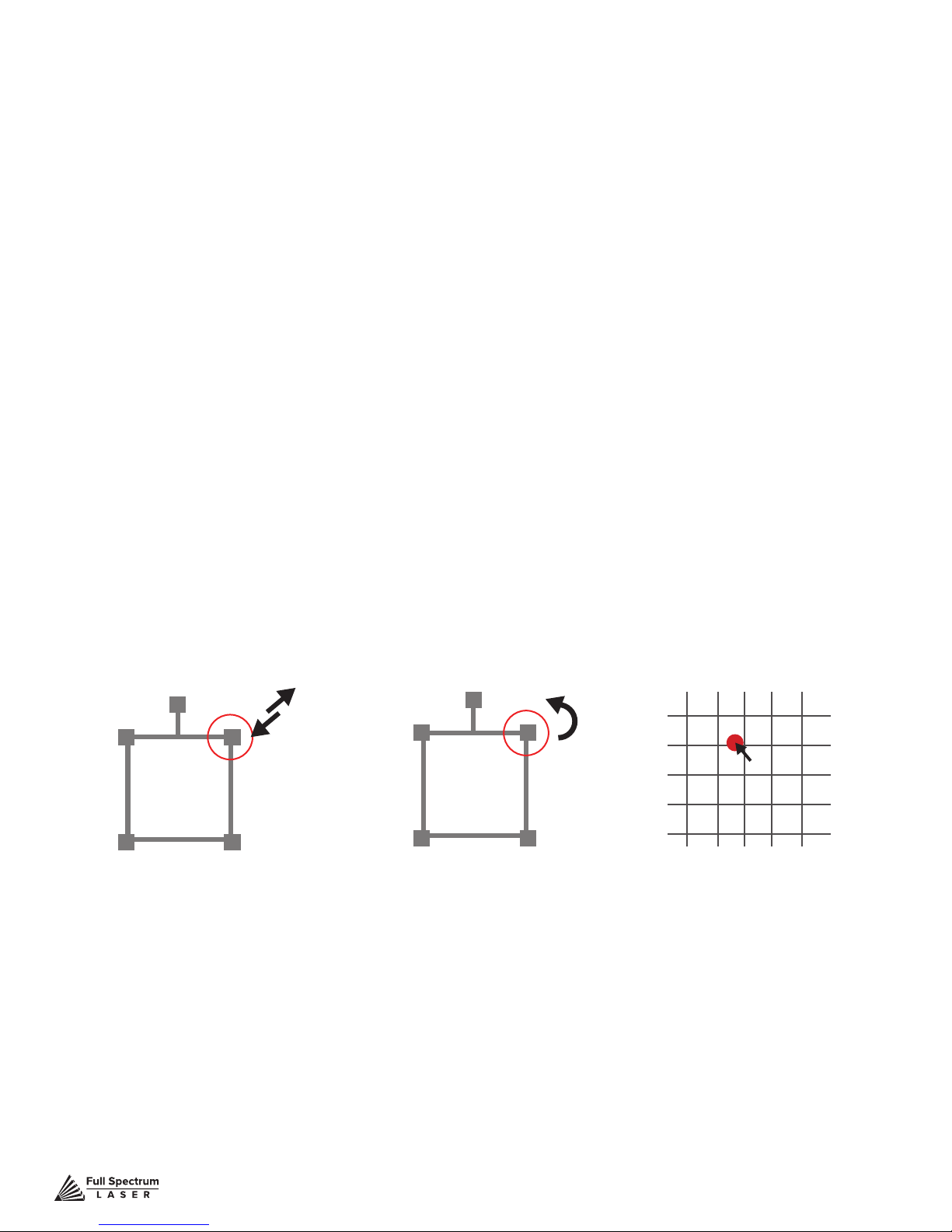
Mouse Controls
A. Drag ‘n Drop
Click and hold a design le and then drag it into the workspace. You will be invited to “Drop
anywhere!”. Once uploaded, click and hold the left mouse button and drag the mouse to move the
object in the workspace.
B. Resize / Rotate
Clicking on the object with your mouse will highlight the square adjusters for size and orientation. Use
the mouse to manipulate the object’s size by expanding or constricting the square adjusters or turning
the rotation node to rotate object.
C. Alt + Left Click to Rotate
Hold the Alt button on your keyboard, then left click and hold your mouse over the rotation node. By
moving the mouse, you can resize the object from center rather than the corner.
D. Alt + Left Click to Resize
Hold the Alt button on your keyboard, then left click and hold your mouse over one of the four corner
“resizing” nodes. By moving the mouse, you can to rotate the object from the opposing node.
E. Home to Location
Instantly home the laser to any location in the work bed by simultaneously holding the Ctrl key and
left-clicking the mouse. This allows you to choose where the laser starts the job.
Mouse Controls
Resize Rotate Home to Location
Technical Support is available from 8am to 5pm (PST) M - F at [email protected].
84
Page 86
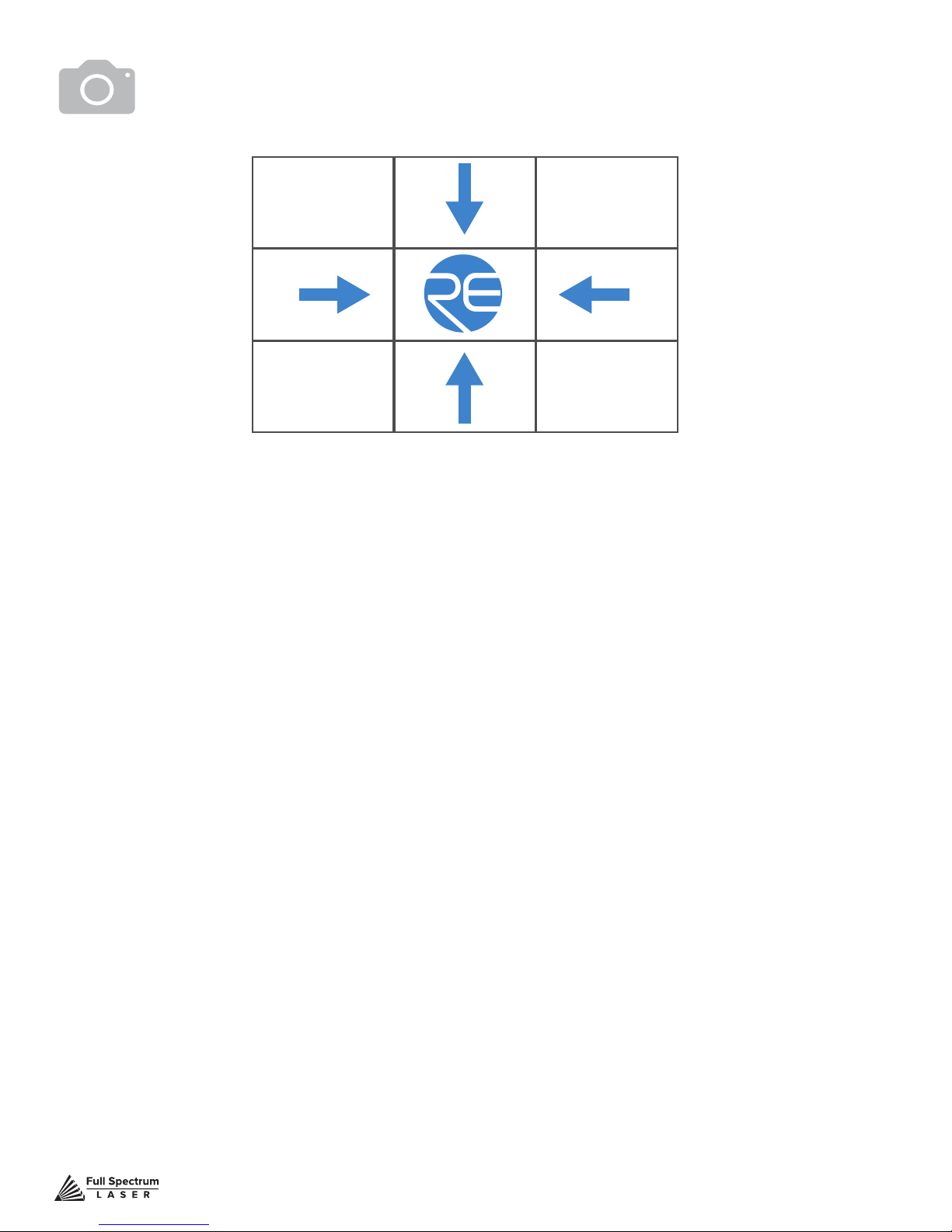
Camera: Capture Workspace
Use the onboard camera to capture your workspace to align your design.
Figure 7.18
1. Place material in center of laser bed.
2. Position the laser head above the material and use the focus billet to focus the cone above the
material surface. Ensure your material does not impede the movement of the laser head.
3. Initiate Camera Sequence - Press the Camera Icon on your RE2 software, or on the LCD touch
screen (for touch screen controls, see user manual) - Note that you 1) use the camera button, 2)
position the head, and 3) press the camera button again (this initiates sequence with no indication on
software). Follow the steps on the screen. Click “New Height Measurement”. The laser head will shift
back and measure the height of your material using the secondary red beam laser. You can repeat
this step several times for more accurate results. If results don’t improve, it may be that your material
is an uneven surface. Click Continue when focused.
4. After 9 photos are taken and stitched, your workspace should now represent your laser bed.
Position your design as needed (for help importing, see the Work-Flow Section), and adjust setting.
5. You are now ready to run your job! To double check a position on your workspace, CTRL-Click
anywhere on the work space to position the laser head there.
Technical Support is available from 8am to 5pm (PST) M - F at [email protected].
85
Page 87
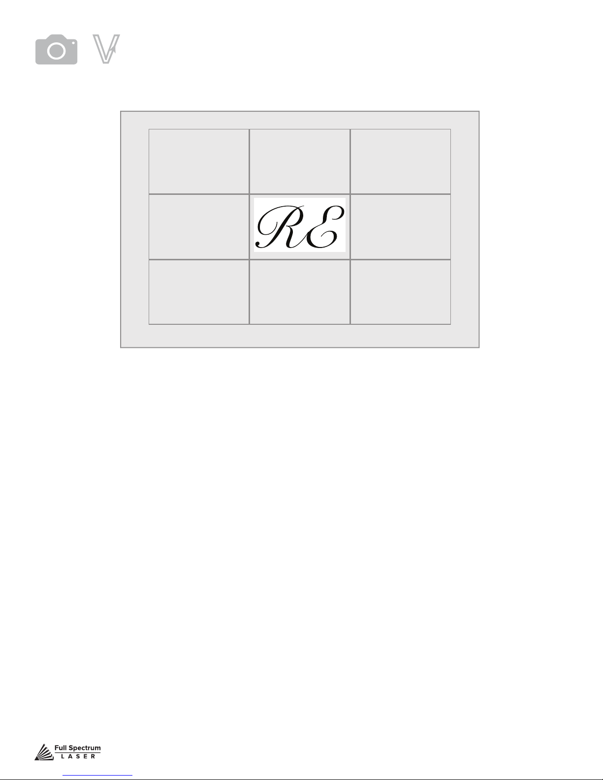
Camera:Vector Trace
Use the onboard camera to capture your workspace to align your design.
Figure 7.19
Tape
MASKING TAPE OVER WORK AREA
1. Choose your material, and prep. Flat objects work best, and we suggest you place masking tape
(paper tape) on the surface before marking with a pen (sharpie). Don’t allow the masking to tape to
overlay on the material when applying more than one strip.
2. Using a thick black marker or pen, draw on your material. Thick solid lines will be read the best. If
coloring in a space, ensure completely lled in.
3. Capture the workspace as shown in steps 3 & 4 in the “Capture Workspace” instructions.
4. Click on the “Vectorize” icon in the top menu bar (show with label). This will bring up a sub-menu.
Using your mouse, select the section you want to vectorize and press ok. You can repeat this step
as many times as you like. Place a white piece of paper behind your self-drawn design to help aid if
having trouble capturing the area you want to vectorize.
5. You now have Bitmap and Vector data for your object available.
They should appear in the Object Manager box. Delete data not needed. If just engraving, delete
vector data, if just cutting or marking, delete bitmap data.
6. You are now ready to run your job!
Technical Support is available from 8am to 5pm (PST) M - F at [email protected].
86
Page 88

Maintaining Your Camera
Follow these simple tips to keep your camera clean and functioning at peak performance:
Just like with mirrors, you will need to clean the camera lens periodically. Use lens wipes to gently
clean the camera lens as needed.
Your camera system comes with a lens cap. When using the camera, remove this lens and keep in a
safe place. It is recommended that this cap be placed on the camera lens when the camera is
not in use.
Just like with mirror alignment, it may occasionally be necessary to correct the camera offset if the
camera is bumped or jostled. Follow the “Correcting Offset Camera Calibration” instructions below.
Camera: Height Calibration
Muse can detect the height of the material using the camera features. It is possible, however, that the
height calibration can be jarred out of alignment. To check height calibration, follow these instructions:
Height Calibration Test
1. Remove all objects from the interior workspace, including the honeycomb tray.
2. On the Touch Screen, click the camera icon. A popup screen will appear.
3. Click “New Height Measurement”. You will see a range of numbers appear. If the numbers are all
within 5/-5, the height calibration is acceptable. If the numbers are not within 5/-5, you will need to
adjust Height Calibration.
Height Calibration Procedure
1. On the Touch Screen, click the settings icon. Then click “Advanced”. Scroll to the bottom
of the page.
2. Click “Calibrate Height”. You will receive the following warning:
“Changing Height Calibration may invalidate custom Position Calibration data on the device.
It’s recommended to run this before calibrating camera position. If you already have position
calibration, this will be incorrect and must be recalibrated if height calibration is changed.”
3. Click “Conrm”. The following instructions will appear:
“This page lets you calibrate the height measurement laser for the camera. It’s recommended to
use a stack of 18 US Quarters and opaque tape to reduce the reectivity. However, if you don’t
have this, you can enter a custom calibration material thickness. All objects you use for height
calibration must be of identical height. Start with nothing in the laser bed for an initial measurement.
Then place three quarters, or your custom material, under the red laser. Click measure, then repeat
with more height each time until enough data has been collected.”
Again, it is required that the interior workspace be free of all objects, including the honeycomb tray.
4. Click “Measure”. The laser head will move to a xed position in the workspace. Place your three
stacked quarters under the red beam dot. Click Measure and repeat until 5 measurements are
taken. Note that the editable height default is 5.25 millimeters, the height of 3 US quarters. This
number can be adjusted for other coins or measuring blocks. After the 5 measurements, the Total
Height Measurement should be equal to or greater than 30 millimeters.
It is important to note that when a new height calibration is performed, the position calibration will
have to be re-calibrated, as well. This is not the case in reverse, however, and height calibration is
not necessary after position calibration
Technical Support is available from 8am to 5pm (PST) M - F at [email protected].
87
Page 89

Camera: Position Calibration
This tool allows you to set image offsets at multiple points around the camera snapshot. Whenever
the snapshot function is used on materials of similar height, this calibration will be used to ne tune
the camera result. You may need to add additional calibration for materials of different heights.
1. On the Touch Screen, click the settings icon and then click “Advanced”. Scroll to the bottom of
the page and click “Calibrate Position”. Click “Conrm” and follow the on-screen instructions. They
will begin by telling you, “Height calibration and stitching need to be performed prior to proceeding.”
2. Click “Activate”. This will cause the laser head to move to a xed position in the workspace.
3. Place a sheet of thin material (a sheet of lined paper works well) under the red beam dot. It
will be helpful to mark the page with a “+” symbol to create an identiable target to align with.
Remember, your machine’s interior should be empty, including removing the honeycomb tray.
Click “Done”.
4. Click “Measure”. The laser head will move to a xed position in the workspace. Note, that when
you select “Measure” for the rst time, and the laser head moves to that xed location, it will set a
base height. You will also need to click “Done” between measurements. Place your three stacked
quarters under the red beam dot. Click Measure and repeat until 5 measurements are taken.
Note that the editable height default is 5.25 millimeters, the height of 3 US quarters. This number
can be adjusted for other coins or measuring blocks. After the 5 measurements, the Total Height
Measurement should be equal to or greater than 30 millimeters.
5. Click “View”. You will see the camera snapshot of the interior workbed. Click “Done”.
6. Click “Calibrate” and then click “Conrm”.
7. You will be taken to a new screen on the touch panel. At the top of the touch screen, the image
you took is displayed. You can zoom and move the crosshairs with your ngers. Pick a spot,
preferably your marked crosshairs, and manually maneuver the crosshairs over the mark you put
on the paper. Click “Set Calibration Point”. The red dot will move into position over that spot.
8. Next, look at the position of the red dot in the interior of the machine. If it is not directly over your
target, use the slow jog buttons to bring the red dot exactly aligned with the mark.
9. When you are satised they are aligned, click “Set Offset Point”.
10. You can back up or repeat the process, if desired. Click “Finish”.
11. Click “Conrm”.
Technical Support is available from 8am to 5pm (PST) M - F at [email protected].
88
Page 90
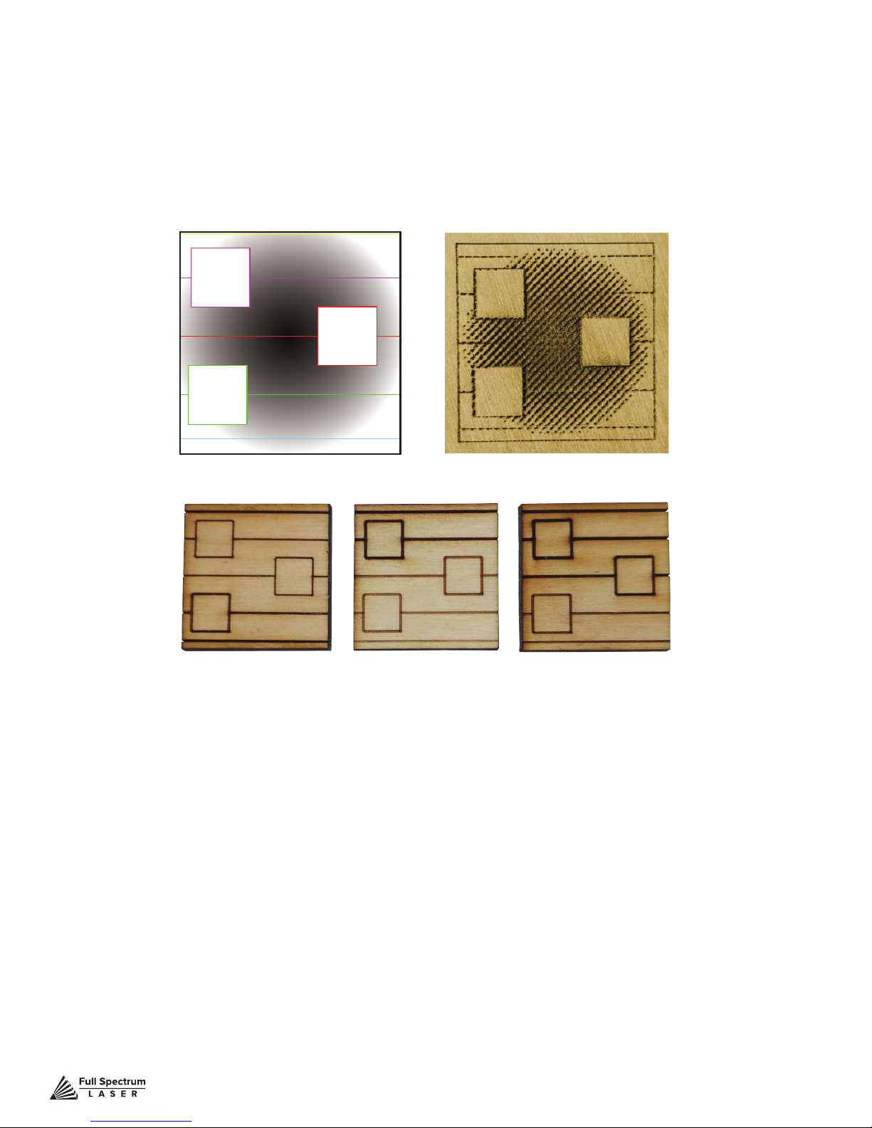
Materials Testing
Muse is capable of cutting a wide range of materials. Common materials include wood, cardboard,
paper, fabric, acrylic, leather, and many more. Muse can also engrave on tile, stone, glass, and other
hard surfaces. Muse is not designed to cut metal of any type. If you have any questions whether a
material is suitable for a CO2 laser, contact the material manufacturer before use.
Figure 7.20
Dithered ExampleSample File
Vector Examples from Dark to Light
Using suitable materials will still have wide variance in power, current and speed settings depending on the properties of that material, such as density and thickness. For example, wood can be soft
(pine) or hard (oak), depending on the source. Settings will also be determined by vector or raster
choices, depth of the cut and overall desired outcomes. This makes it difcult to provide operators
with exact settings for each type of material. Instead of giving inaccurate data, operators should become accustomed to material testing.
Full Spectrum Laser provides a free materials test template with suggested starting points in power
and speed settings. From there, you can experiment with your own materials testing. Once the perfect settings are determined, we recommend recording those results in a Materials Log.
To access the material test templates, complete material testing instructions and a free materials log,
go to http://laser101.fslaser.com/materialtest.
Technical Support is available from 8am to 5pm (PST) M - F at [email protected].
89
Page 91

SECTION VIII. HARDWARE & MAINTENANCE
With a little care and maintenance, your Muse Laser Cutter will remain clean and continue to run at
top efciency for years to come. Be aware of all safety and maintenance issues with your machine
by following all the safety instructions in this manual.
Replacing the Laser Tube
This section provides procedures and a walkthrough to replace the laser tube on your Muse. Although
it should last for hundreds of projects, the laser tube is considered a consumable and will eventually
need to be replaced. Please carefully read all instructions before beginning the replacement
procedure as there are several critical steps which must be properly followed to avoid breaking the
laser tube. The included pictures show how to properly connect wires to the tube’s electrodes and
secure the connections.
REQUIRED PARTS AND TOOLS:
• 45W REPLACEMENT TUBE
• 2.5 MM HEX WRENCH
FRAGILE GLASS!
your laser tube at the neck. The water connections are very
fragile, DO NOT pull or force the connection tubes— gently
work the tubes off of the connectors.
SHOCK WARNING! The capacitors in the power supply
retain power even after turning the laser off. To ensure your
safety, turn off the laser, remove the power cord and wait at
least 1 hour before accessing the power supply.
Pulling on the tube wires will break
Technical Support is available from 8am to 5pm (PST) M - F at [email protected].
90
Page 92
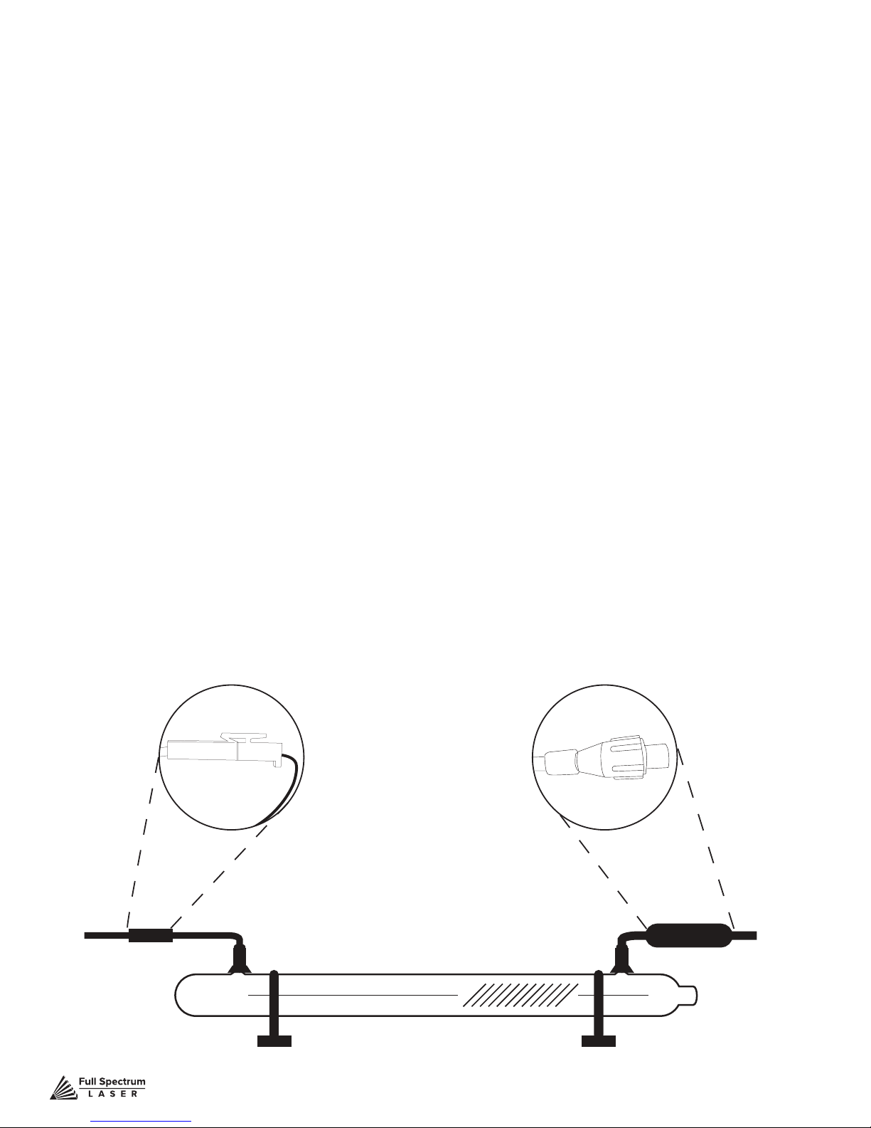
Replacing Laser Tube Steps
1. Power Off Machine: Power off and unplug your unit. Wait at least 1 hour for capacitors
to discharge.
2. Disconnect Water: Detach the water tubes from their connectors on the laser tube and drain
the water into a bucket.
3. Remove Water Tubes (Step One): Remove the two (2) water tubes from the bulkheads on
the back of the machine and carefully drain any water into a bucket. Use the small piece of tubing
that shipped with your laser to shunt the two water bulkheads in the back of the machine together.
4. Remove Water Tubes (Step Two): GENTLY remove the water tubes from the laser glass
bulkhead. Be careful not to let any excess water in the tubes spill onto the machine’s components.
5. Remove Tube Retainer Straps: Using a 2.5mm hex wrench (included with your purchase),
remove the four (4) M5 hex nuts from the two (2) tube retainer straps that hold the laser tube in the
rubber restraints.
6. Remove Old Laser Tube: Remove the tube from the rubber holders and carefully set it on
top of the machine. Be aware the laser tube is still connected to the machine’s wiring.
DO NOT pull on the wiring.
7. Remove Universal Laser Pin Connector: Carefully unscrew the universal laser pin
connector off the aperture end of the laser tube. Next unclip the connector on the other side of the
laser tube. You can now place the old laser tube aside for later disposal.
Figure 8.1
Technical Support is available from 8am to 5pm (PST) M - F at [email protected].
Coils to the Right
91
Page 93

8. Reattach Universal Laser Pin Connector: Reverse step 8. Screw the universal laser pin
connector onto the aperture end of new laser tube and clip the connector back to the other end of the
laser tube.
9. Place New Laser Tube: Place the new tube into the rubber holders in the same orientation
as the old tube was in when it was removed (with the glass coils oriented to the RIGHT when
facing the machine).
10. Re-Attach Tube Retainer Straps. Gentle place the tube restraining straps back into
position over the rubber holders and secure the new laser tube in place.
11. Re-Thread Hex Nuts. CAREFULLY re-thread the M5 hex nuts onto the U-bolt posts and
make snug (but not yet tight) with the rear panel.
12. Re-Attach Water Tubes. Carefully re-attach the water tubes to the proper laser connection
bulkheads. Make sure that the water tube routing and locations match the original conguration.
We have now switched the old laser tube for the new laser tube.
You will need to retest the mirror alignment and possibly go through the
mirror alignment procedure again.
Technical Support is available from 8am to 5pm (PST) M - F at [email protected].
92
Page 94

Belt Installation
The belts on your laser system are a consumable item and will eventually stretch beyond a usable
length or break. You can contact Full Spectrum Laser support for replacements.
SHOCK WARNING! The capacitors in the power supply
retain power even after turning the laser off. To ensure your
safety, turn off the laser, remove the power cord and wait at
least 1 hour before accessing the power supply.
WATER WARNING! You will be disconnecting the water
system and working with the laser upside down. Be sure the
machine is dry before proceeding with this process.
REQUIRED PARTS AND TOOLS:
2.5mm Hex key (included with accessories)
1. BELT INSTALLATION STEPS:
Power Off Machine. Power off and unplug your unit. Wait at least 1 hour for capacitors to discharge.
2. Disconnect Water: Detach the tubes from the rear connectors. Use the small piece of tubing
that shipped with your laser to shunt the two water bulkheads together.
3. Loosen Retaining Screws: Loosen or remove the M3 retaining screws and washers so that
the old belt can be removed and discarded.
4. Mount Belt: Run each end of the new belt through the mounting slot with the teeth on the inside
of the closed loop. The ends of the belt should protrude by approximately 3 teeth (6mm) through the
slot. Make sure that the belt forms a at, closed loop.
5. Tighten Retaining Screws: Tighten the M3 retaining screws to secure and retain the belt.
Starting the thread with your ngers can speed the process up.
6. Loosen the idler pulley mount: Once the belt has been installed on the riser, loop over the
drive and idler pulleys.
7. Tension the belt: Pull on the Y idler pulley mount with your hand. Moderate to strong force is
recommended. If the motors do not jog, verify that the motors are connected to the control card.
Technical Support is available from 8am to 5pm (PST) M - F at [email protected].
93
Page 95
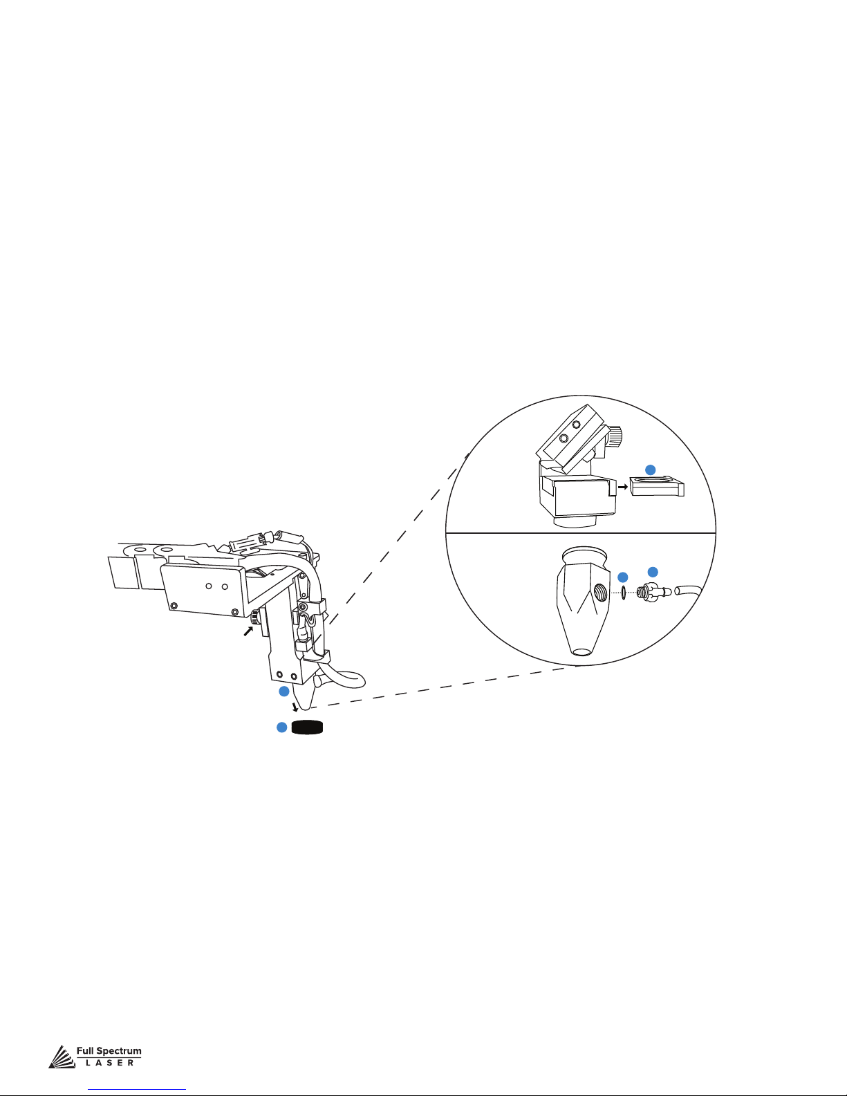
Focus Lens Replacement Instructions
Parts: Air Assist Cone (A) – Fitting O-Ring (B) – Air Assist Fitting (C) – Focus Billet (D)
– Focus Lens w/ case (E)
Instructions:
1. Loosen the focus head thumbscrew, slide the focus head to the uppermost position and
tighten thumbscrew.
2. Disconnect air hose by gently pulling it.
3. Using a 1.5 hex wrench (not included), loosen the “set” screw, but do not remove.
4. Remove the current air assist cone.
5. Place the tting O-ring on the air assist tting and attach to new air assist cone.
6. Place new air assist cone under focus lens and into slot. Tighten “set” screw with a 1.5
hex wrench. Reattach air hose.
7. Slide the current focus lens out of the slot. This does not require tools.
8. Slide new lens into slot.
E
C
B
Thumbscrew
A
Figure 8.2
D
Maintenance: The Focus Lens will need, at minimum, weekly cleaning, depending on usage and
types of materials used. Only use optical grade lens wipes and gently wipe the surface of the lens
clean. Save the case the lens came for storage when switching to a different lens. With any lens,
always use the correct focus billet and air assist cone.
Lens Descriptions:
1.5” lens is appropriate for extra ne engravings such as fonts below 6pts.
2.0” lens* has a good combination of ne engraving and thin cutting for fonts between 6pts and 8pts.
2.5” lens is appropriate for cutting up to ¼” of material and engraving detail to around 8pts.
5.0” lens is for cutting thick foam. it is also a good lens for engraving into deep bowls, when more
room is needed.
*This is the included lens for Muse
Technical Support is available from 8am to 5pm (PST) M - F at [email protected].
94
Page 96

General Maintenance
Before Every Job:
- Always be sure your water, air, exhaust, and power systems are properly assembled and operating normally.
- Be sure that the machine and workspace are clutter-free.
- Be aware of any material warnings and that you are working in a well-ventilated workspace.
- Check that your re extinguisher is up to regulation and is easily accessible.
- Always follow all safety protocol.
Weekly
- Wipe down the walls the machine with a clean rag.
- Use optical grade lens wipes to clean both sides of the beam combiner, all mirror surfaces, the focus
lens, and the tube aperture. Optic surfaces may need to cleaned more often if cutting materials produce
excessive residue (possibly daily).
- Clean fallen debris from the catch tray of the machine. Less excess material will reduce re risk, and
provide for better exhausting.
- Always keep rails, motors and moving parts free from excess material as it can obscure movement and
cause damage.
Monthly
- Check rail lubrication. When the laser arrives, you should be able to visibly see the lubricant on the X
and Y rails. These rails will not need to be re-lubricated often, but check monthly to be sure that the rails
are properly lubricated and aren’t grinding or catching.
- Check your fume extractor lters. Depending on your output and the materials being cut, your fume
extractor lters may need to be replaced as often as every month (or sooner).
Quarterly
- Change water in cooling system. This will keep your tube safe from unwanted debris, mold or evaporation.
- A chiller system is enclosed and will stay relatively clean and undisturbed, but it is good practice to check
and change the water as needed.
- Check for wear on belts. Well lubricated belts should last, however, eventually they may wear and crack
and need replacement.
Technical Support is available from 8am to 5pm (PST) M - F at [email protected].
95
Page 97

Appendix A: Coolbox
Unboxing
Carefully remove the items from the box as directed.
1. Remove the Top Foam: Beneath the top foam, you will see the coolbox and all needed
accessories.
2. Remove Right Packaging Box: Remove the larger box to the right and check that all the following
parts are included: 2-Pin Cable (1), 4-Pin Cable (1) and AC Power Cable (1).
3. Remove Right Packaging Box: Remove the smaller box to the left and check that all the following
parts are included: Cooling Fan (1), 4-Pin Molex to 4-Pin Terminal Connector (1) & and a small plastic
bag containing: 2mm Hex Key (1), 2.5mm Hex Key (1), 5.5/7mm Wrench (1), two M3 Nuts (2) and
four Acorn Nuts (4).
4. Remove Coolbox:Start by removing the three pieces of side foam, securing the coolbox. Then,
gently lift the coolbox from the box. You can lift and remove the adapter plate and the foam sheet at
the same time as the coolbox.
5. Remove Exhaust Fan Cowling:Remove the exhaust fan cowling and its support foam.
6. Remove Muse Side Panel: Remove foam covering the side panel. Remove the new Muse side
panel from the box. Your coolbox is unboxed.
Parts Checklist
Coolbox Unit (1)
Exhaust Fan Cowling (1)
Adapter Plate (1)
2-Pin Cable (1)
4-Pin Cable (1)
AC Power Cable (1)
Cooling Fan (1)
Connector (1)
2.5mm Hex Key (1)
5.5/7mm Wrench (1)
M3 Nuts (2)
M4 Acorn Nuts (4)
Assembly
1. Safety First: Before starting this procedure, turn off your muse and unplug it from all power
sources. We recommend to wait at least 20 minutes to ensure no residual electricity remains.
2. Remove Existing Exhaust Plate: Using the provided 2.5mm hex key, remove the four (4) screws
from the existing exhaust plate and set them aside in a secure location. Then remove the existing
exhaust plate. You will no longer need the old exhaust plate, however, hold on to two (2) of the screws
to secure the new adapter plate, in the next step.
3. Attach Adapter Plate: Using the 2.5mm hex key and the two (2) screws saved from removing the
exhaust plate (see step 2), attach the adapter plate on the back of your Muse, where the old exhaust
plate was.
4. Attach Exhaust Fan: Using the 5.5/7mm wrench, attach the exhaust fan to the adaptor plate with
the two (2) M3 Nuts. Note that the arrow on the fan needs to be pointing out the case.
5. Connect Exhaust Fan to Cowling: Carefully connect exhaust fan connector to exhaust fan
cowling connector. Do not force the connection. The connectors only t one way and should gently
slide together and secure.
6. Attach Fan Cowling to Adapter Plate: Carefully slide the fan cowling onto the adapter plate by
aligning it straight and then pushing forward. Hold the cowling steady and secure with the four (4)
acorn nuts. Tighten until secure using your ngers or the provided 5.5/7mm wrench.
IMPORTANT: Once cowling is attached, make sure the wires are not interfering with the fan. Inspect
visually and then spin the fan by hand from the inside of the Muse to ensure it is unobstructed.
Technical Support is available from 8am to 5pm (PST) M - F at [email protected].
96
Page 98
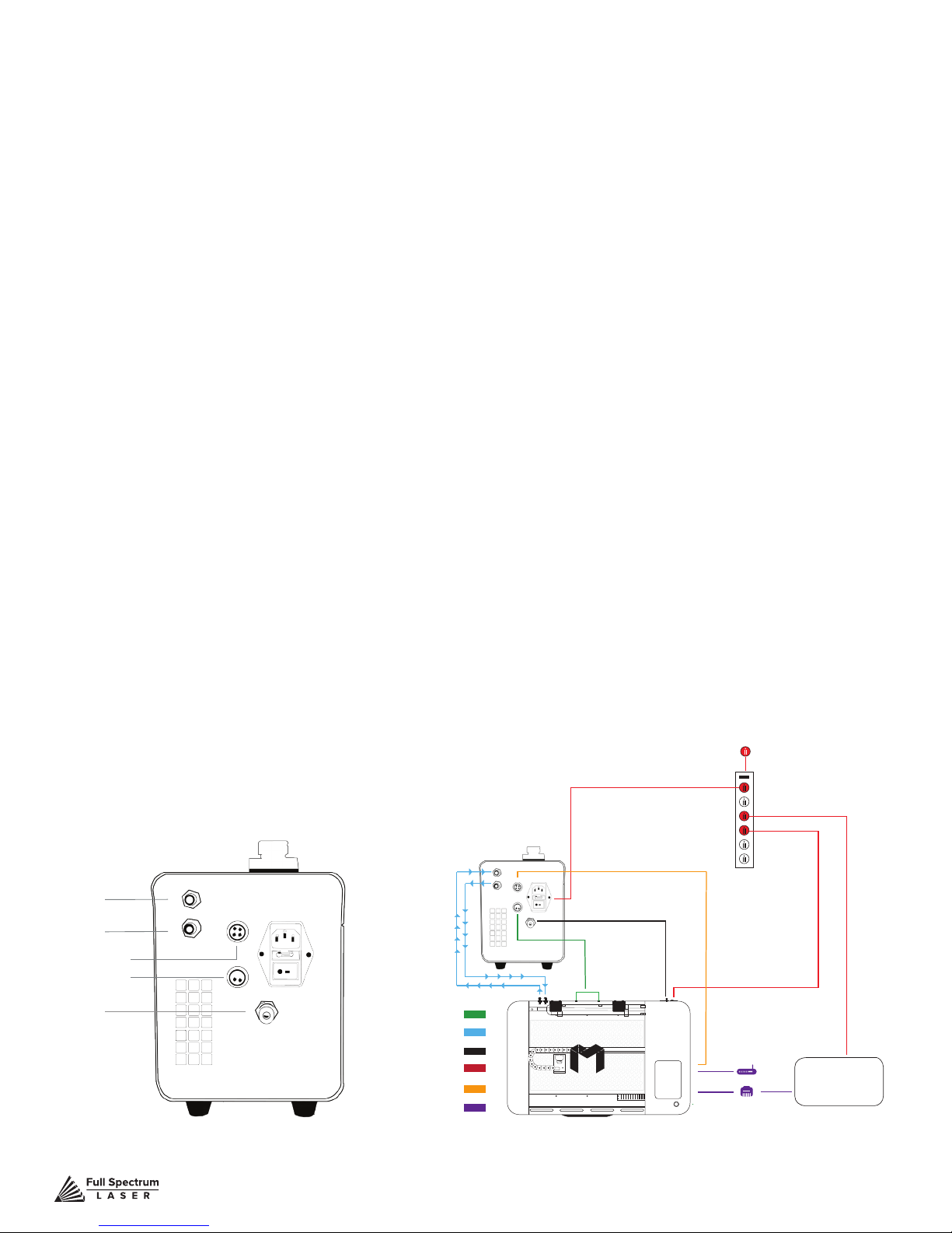
7. Connect Air Assist Hose to Coolbox: Disconnect the air assist hose from your existing air pump.
Do not disconnect the other end of the air assist hole from your Muse. Next, attach the air assist hose
to the “Air Out” port on your coolbox.
8. Connect Exhaust Fan to Coolbox: Using the provided 2-Pin Cable attach one end to the slot on
the fan cowling and the other to the back of the coolbox, in the slot labeled “Exhaust Control”. Once
each is snug in the slot, gently turn the metal rings on each end of the connector and tighten.
9. Connect Side Panel to Coolbox: Using the provided 4-Pin Cable attach one end to the slot on the
new side panel and the other to the back of the coolbox, in the slot labeled “Machine Control”. Once
each is snug in the slot, gently turn the metal rings on each end of the connector and tighten.
10. Connect Water Tubing to Coolbox. WARNING: The water tubes may contain water if you have
used the machine. Have a towel ready to catch any excess water that may pour out of your tubing
and avoid spilling on electronic components or sources of electricity. Detach the “Water In” water
tube from the existing water pump and securely attach it to the “Water Out” slot on the back of the
coolbox. Next, take the unconnected “Water Out” tube (the end that went to your water bucket) and
securely attach it to the “Water In” slot on the back of your Muse. This will create the proper circulation
of water through the laser tube and back to the coolbox.
11. Connect Ducting to Exhaust Port: Place your 4” ducting over the Exhaust Port located at the
back of the machine and hold. Secure with 4” ducting clamp or industrial ducting tape.
12. Connect Power Cord: Insert the Non-Outlet end of the power cord to the back of the coolbox, in
the AC power slot just above the power switch. Next, plug the other end into an appropriate outlet. DO
NOT plug the Coolbox into the slots in the back of your Muse.
Using Your Coolbox
1. Add Distilled Water: Unscrew water cap. Fill tank with distilled water (approx. 1250 ml). Put cap
back on and tighten.
2. Power On Coolbox: Flip the red power switch to the “On” position. Remember to always run your
coolbox when the laser is operating
Machine Control
Air Tubing
Options
Computer
Water In
Water Out
Machine Control
Exhaust Control
Air Out
Water In
Water Out
Exhaust Control
Water Tubing
Air Tubing
Power Cords
Machine Control
Software Connection
Water InWater Out
Exhaust Control
Technical Support is available from 8am to 5pm (PST) M - F at [email protected].
97
Page 99
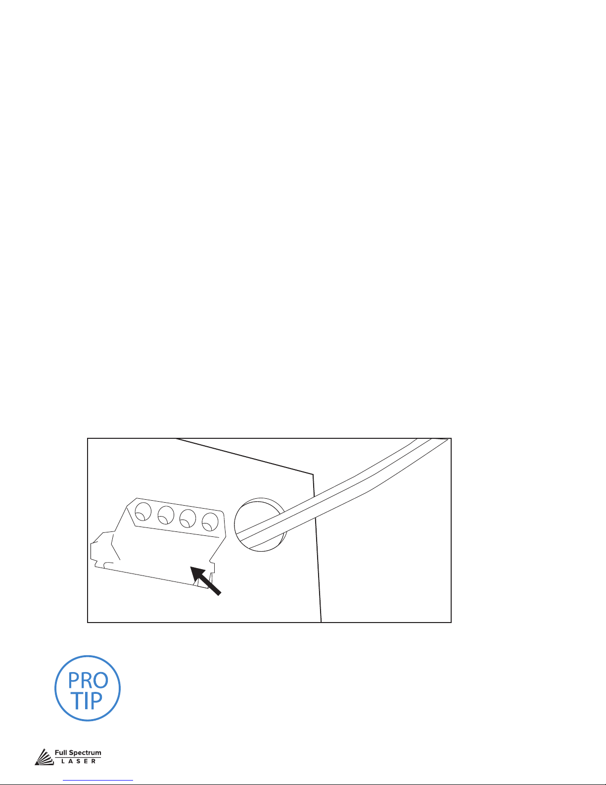
Appendix B: Rotary Attachment Installation
The Full Spectrum Laser Hobby Advanced Rotary Attachment is an accessory to the Muse Laser
System and is not included with the base purchase. You can order the rotary attachment from the Full
Spectrum Laser website at http://fslaser.com/Products/LaserAccessories. The rotary attachment is
capable of engraving on objects from 0.25in diameter.
ROTARY ATTACHMENT INSTALLATION
The rotary attachment is a friction-wheel type—objects rest on two driven and two idling wheels and
are turned to engrave an image onto the surface of a cylindrical object. The rotary attachment works
by translating Y motion along a cylindrical surface.
INSTALLATION STEPS
1. Power Off Machine: Power off and unplug your unit. Wait at least 1 hour for
capacitors to discharge.
2. Position Rotary: Place the rotary attachment into your laser’s work area.
3. Connect Rotary:
the rotary attachment motor keeping the same orientation as in the diagram below.
4. Switch to Rotary Mode in Software: The nal step is to inform the software you are using the
rotary. To do this, Click the Edit button, then click Settings. This will bring up the Settings menus. Click
Device. Under device options there is a slide bar across from “Rotary Mode”. Click the slide bar and
make the bar blue. Next, below Rotary Mode, there is a bar for Laser Positioning. The rotary requires
this to be set to Relative Positioning. Finally, click Save Changes at the bottom of the screen. The
rotary is now ready for use.
You can switch from Relative Positioning to Absolute Positioning by going to Settings, within the Edit
drop-down options. Click Settings>Device. Next, choose Absolute Positioning or Relative Positioning
on the slide bar across from Laser Positioning. Click Save Changes when you are done
Find the rotary connector inside the machine under the LCD display. Connect
Figure 8.3
PRO TIP! Once you have connected your rotary attachment,
you can activate your laser and move the rotary attachment and
laser head into a position to engrave on your workpiece. The
red dot should be in the same vertical (X-Z) plane as the center
axis of the workpiece.
Technical Support is available from 8am to 5pm (PST) M - F at [email protected].
Rotary Connection
98
Page 100
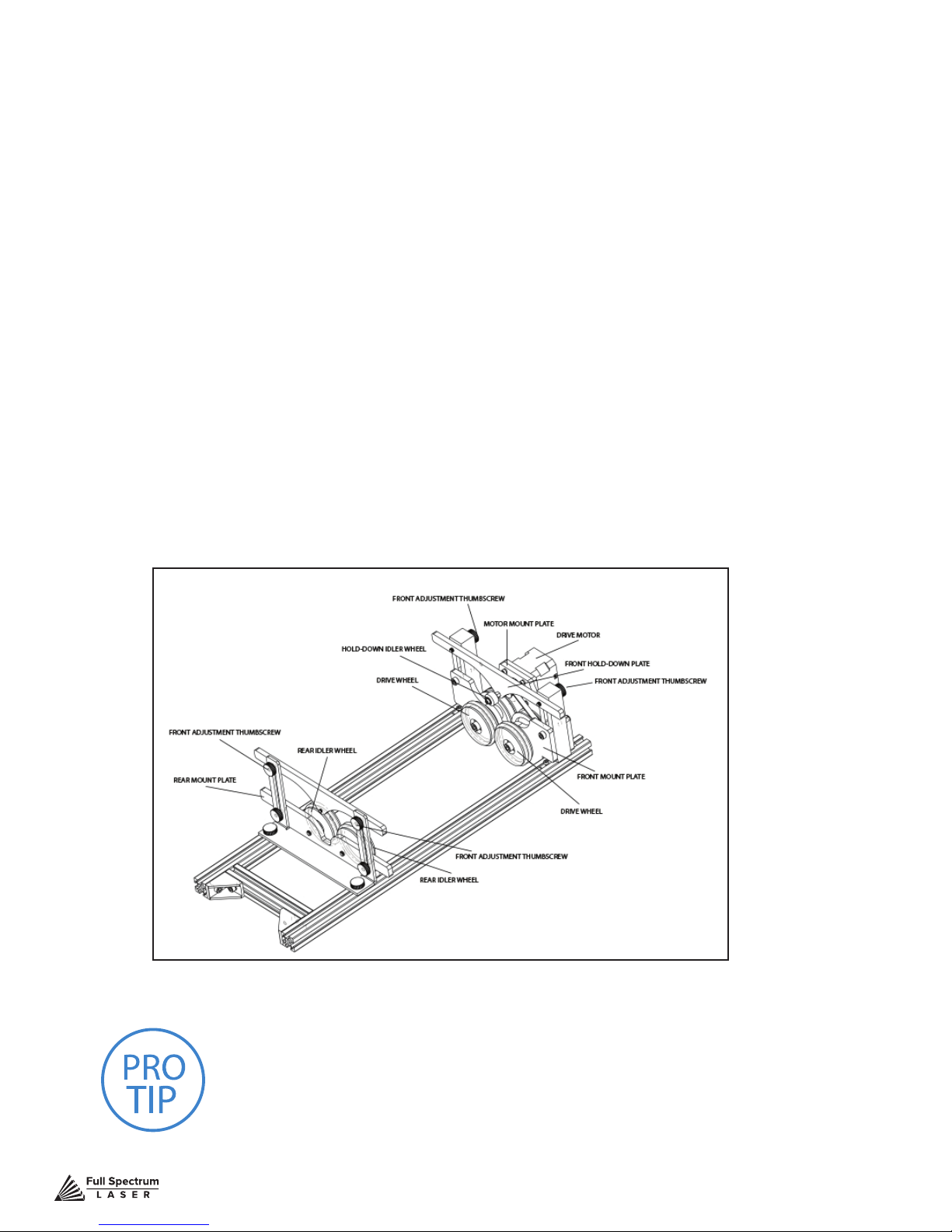
Appendix C: Using the Rotary Attachment
The rotary attachment is designed to be used within the laser case, however its maximum engraving
diameter can be increased by modifying your laser system’s bottom panel. Please be aware that
any system modications must be performed by an authorized technician and in accordance with all
applicable state and federal laws.
ALIGNING YOUR ROTARY ATTACHMENT
The best way to align your rotary attachment with the laser head is to build a jig that uses the frame as
a reference. This is a very quick process.
1. Starting Position: Focus the laser head onto the rear frame of the rotary attachment on the far
left when facing the machine from the front.
2. Slide: With the red dot visible, slowly slide the laser head to the right.
3. Align: Adjust the positioning of the rotary until the red dot tracks back and forth evenly down the
center. Note that the rotary is not assembled to the body of the machine but is freestanding. You may
need to re-align your rotary each time you use it.
Figure 8.4
PRO TIP! Rotary engraving is best performed along the
topmost area of the project. It is crucial that the rotary be
level. Use a small carpenter’s level to be sure your rotary is
at within the interior of the laser cutter.
Technical Support is available from 8am to 5pm (PST) M - F at [email protected].
99
 Loading...