

Page 1
TCP-485 WiFi
SERIAL / WI-FI CONVERTER
Have this manual in your hands
using the FG Finder application.
Wi-Fi
Supervisory
system
WARNING
BEFORE INSTALLING THE CONTROLLER WE RECOMMEND READING THE INSTRUCTION
MANUAL THOROUGHLY IN ORDER TO AVOID POSSIBLE DAMAGES TO THE PRODUCT.
PRECAUTIONS WHEN INSTALLING THE PRODUCT:
Before performing any procedure in this instrument, disconnect it from the mains; make sure the
instrument has proper ventilation, avoiding installation in panels containing devices that may force
it to work outside the specified temperature limits;
Install the product away from sources that can generate electromagnetic disturbances, such as:
motors, contactors, relays, solenoid valves, etc.
AUTHORIZED SERVICES:
The installation and maintenance of the product must only be performed by qualified personnel.
ACCESSORIES:
Only use original accessories of Full Gauge Controls.
If you have any questions, please contact our technical support.
DUE TO CONSTANT EVOLUTION, FULL GAUGE CONTROLS RESERVES THE RIGHT TO CHANGE THE
INFORMATION CONTAINED IN THIS MANUAL.
ANATEL
"This product is homologated by ANATEL, in accordance with the procedures regulated by Resolution
242/2000, and meets the technical requirements applied."
«This equipment operates on a secondary basis, that is, it is not entitled to protection against harmful
interference, even from the same type of stations, and may not cause interference to systems operating
on a primary basis."
1. DESCRIPTION
The Serial/Wifi converter TCP-485 WiFi allows the interconnection of the Full Gauge controllers
with the supervisory software Sitrad through a WiFi data network using the TCP/IP communication
protocol currently.
Many companies have Wireless routers in their facilities, and it is posible to use this same network for
data traffic between controllers and Sitrad supervisory software, using the TCP-485 WiFi
converter.
2. APLICATIONS
• Facilities where it is desirable to use the existing Wireless network;
• Facilities that do not have conditions for passing a new Ethernet data cabling;
• Facilities where the cost of the investment in the cabled structure has an impact;
Note: The TCP-485 WiFi converter is designed to work only with Full Gauge Controls
instruments.
3. TECHNICAL ESPECIFICATIONS
Converter power
Power supply provided with the
converter
Operating temperature
Operating humidity
Number of instruments supported
per converter in the RS-485 network
Antenna
Compatibility
Encryption type
Product dimensions
Antenna dimensions
External power supply 12 Vdc / 1A
Input - 100-240Vac (50/60Hz)
Output: 12Vdc / 2A
0 to 50ºC / 32 to 122ºF
10 to 90% UR (without condensation)
32 (without the need for termination)
3,8dBi for a estable high quality connection
IEEE 802.11 b/g up to 54 Mbps
WEP, WPA and WAP2
43,5 x 16 x 34 mm (LxAxP)
34,9 x 175,2 x 13 mm (LxAxD)
RS
485
Serial
comunication
er.01
V
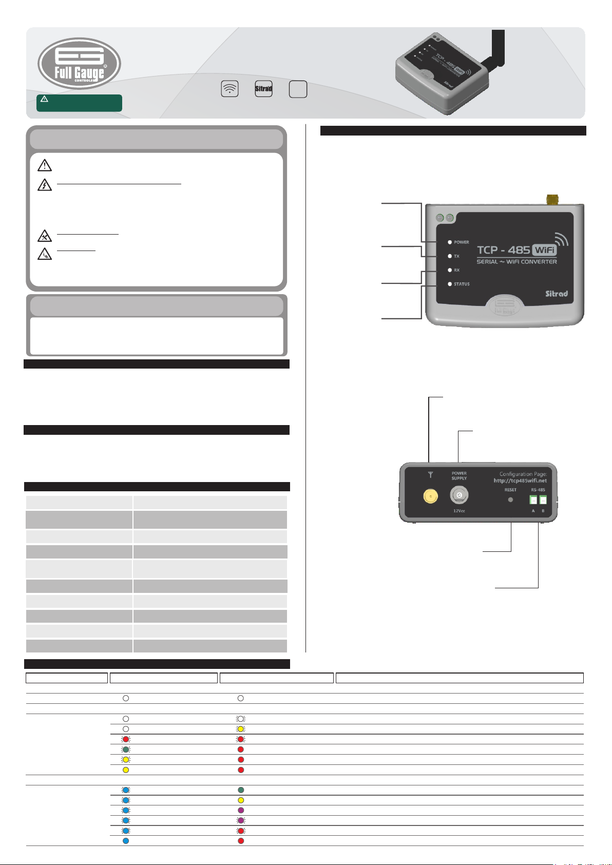
5. INDICATIONS AND KEYS
Power indication
LED - Power and
si gnal s tre ngt h
indication LED
RS-485 network
t r a n s m i s s i o n
indication LED
RS-485 network
r e c e p t i o n
indication LED
Status indication
LED - connection
status indication
LED
Reset - see item 7 - Reset configuration
Communication network with RS-485 instruments
TCP485WIFIV01-01T-16374
Antenna - Connect the antenna
supplied with the converter.
NOTE: Use only antenna supplied by
Full Gauge.
Converter power
4. INDICATIONS
TCP-485 WiFi
ALL MODES
CONFIGURATION
MODE
OPERATION
MODE
LED STATUS / State
White / On
LED POWER / State
White / On
White / FlashingOff
Yellow / FlashingOff
Red / FlashingRed / Flashing
Red / OnGreen / Flashing
Red / OnYellow / Flashing
Red / OnYellow / On
Green / OnBlue / Flashing
Yellow / OnBlue / Flashing
Purple / OnBlue / Flashing
Purple / FlashingBlue / Flashing
Red / FlashingBlue / Flashing
Red / OnBlue / On
Ocurrence
Equipament booting
Contact Full Gauge Controls
Contact Full Gauge Controls
Router connection password error
Equipament scanning the network
Equipament ready to connect
Equipament connected and ready to be configured via internet browser
Excellent signal level
Good signal level
Poor signal level
Very poor signal level
No signal
Connected with Sitrad and communicating
Page 2
6. CONFIGURATION AND INSTALLATION
For the initial configuration, it is recommended to place the TCP-485 WiFi next to the device that
will configure it (e.g. computer, smartphone, or tablet) in order to monitor the configuration status by
using the LEDs of the interface and to avoid external interferences (see Item 9).
The TCP-485 WiFi converter can be configured as Dynamic IP (DHCP) or Fixed IP (Static IP),
Items 6.1 and 6.2 respectively. The converter comes from the factory configured as DHCP, and the IP on
the network is dynamically assigned.
During configuration, check the status of the POWER LED and STATUS LED, which indicate each step
of the configuration, as shown in the signaling table (Item 4).
After configuration, install the TCP-485 WiFi at the desired location and connect the power
source. Confirm the signal quality (Items 4 and 9). If the signal is other than excellent or good, the
connection may be unstable and loss of information may occur. Check whether there is any barrier to
the signal or any equipment that may interfere with the signal quality. If the signal remains poor, try
installing the TCP-485 WiFi in another position or use a Wi-Fi signal repeater. With excellent or
good signal, connect the serial network to Terminals A and B of the converter and make the
configurations using Sitrad, as per Item 8 of the manual.
NOTE: When using a smartphone or tablet to configure TCP-485 WiFi, make sure that the mobile
data network is turned off
6.1 Configuration for DHCP operation (Dynamic IP)
Step 1: After TCP-485 WiFi is powered up and the antenna is properly connected, the Power and
Status LEDs will be white for a few seconds, indicating that the equipment is booting. After this time has
elapsed, the Power LED will turn red and the Status LED will flash green.
At this moment the equipment is looking for available Wi-Fi networks.
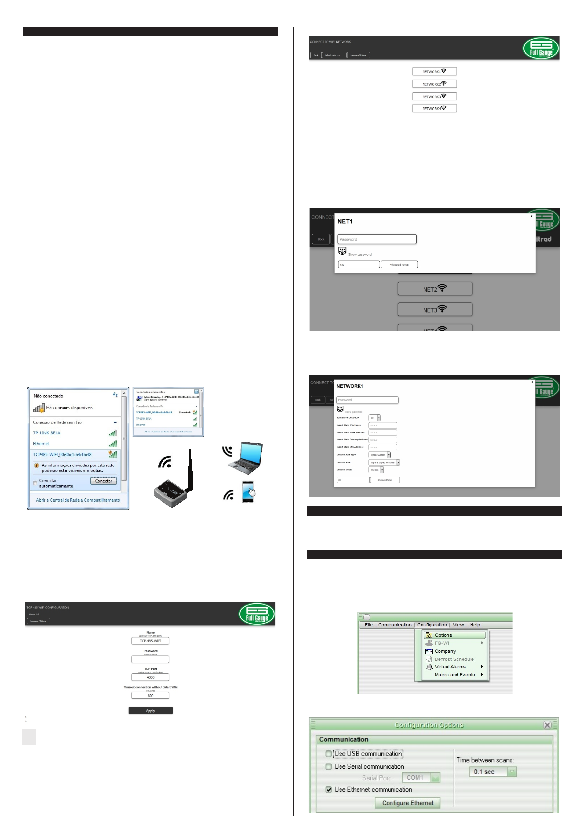
Step 2: Wait for the Status LED to flash yellow and find the network made available by TCP-485
WiFi on your laptop, smartphone or tablet. After clicking on the network to connect, the Status LED
will remain yellow.
Below is an illustration of how the network of TCP-485 WiFi is displayed. The example displays a
connection with the computer using the Windows operating system. The network name will always be
displayed as TC P-485 WiFi accom panied by the MAC address, fo r exam ple:
TCP485_WiFi_00:80:AB:CD:00.
Step 4: Choose which network you want the TCP-485 WiFi to connect to:
On this screen, click on the network you want TCP-485 WiFi to use as a path of communication with
Sitrad.
Step 5: Configures the network chosen for the connection:
The “Password” field must be filled out with the same password used to connect to the Wi-Fi router
6.2 Configuration for IP Fixed operation:
To configure the station to work with fixed IP, follow Steps 1 to 4 of Item 6.1. The fifth step to be
performed is the configuration of the network. Click on “Advanced Configuration” and fill out the fields
with the network details.
Step 3: Using the browser of your device, access http://tcp485wifi.net. No password is required. The
image below shows the splash screen, where you can configure TCP-485 WiFi to operate with
Sitrad.
This screen allows you to configure the name that appears on the station, the password Sitrad uses to
communicate with the TCP, the communication port used to access Sitrad, and the time TCP-485
WiFi waits without data traffic between Sitrad and TCP. After this time, the connection is reset. Click on
“Apply” to validate the fields and then click on “Send” on the next screen to save this configuration in the
equipment.
The monitoring time of lack of traffic between Sitrad and TCP-485 WiFi is used as one of the
means to detect a communication fault. As an exemple, power failure occurs on the computer that is
installed on Sitrad.
7. RESET CONFIGURATION
If you need to restore the factory settings of TCP-485 WiFi, press the reset button until the Power
LED flashes purple. With this procedure, it is possible to the configuration.
8. SITRAD
8.1 SITRAD 4.13
Download the compatible version from: http://www.sitrad.com
Step 1: With the TCP-485 WiFi configured, open Sitrad, click on “Configuration” and then on
“Options”.
Step 2: Select option “Use Ethernet Communication”. Then click on the “Configure Ehernet” buttom
below.
Page 3

Step 3: Click on “New Converter”.
Step 4: At this stage, you can choose the option you want. As an example we will use the option "Scan
the network". After finding your converter in the network, select the desired TCP-485 WiFi and
then click on the “Register Converter” button on the right hand side.
8.2 SITRAD PRO
Download the compatible version from: http://www.sitrad.com
Step 1: After the TCP-485 WiFi configured, run Sitrad, select “Local Server” from the list on the left
hand side and click on “Add Converter” on the right hand side.
Step 2: At this stage, you can choose the option you want. As an example we will use the “Automatic
Search” option.
Step 5: In the figure below, some configurations can be performed, for example such as the access
password equal to the one configured in TCP-485 WiFi, the name to be displayed by Sitrad, and
the TCP version. After performing the configuration, click on “OK”.
NOTE: Sitrad is able to communicate with multiple TCP-485 WiFi converters at the same time. In
this case, in order to improve the connection performance, it is recommended to configure the
instruments that are in the RS-485 of each converter. In Sitrad, click on Configurations → Options →
Configure Ethernet, choose the TCP-485 WiFi to be configured, and click on the Instruments
button. On the screen to the right, select all the instruments belonging to the RS-485 network and click
on “<” button, and then click on “OK”, as shown in the example of the figure below:
Step 3: The name of the TCP-485 WiFi must be displayed as configured in the web page of the
converter. If not, the “Refresh” button starts a new search for the converter in the network.
Step 4: Click on “Select” to register the new converter. Check if everything is okay in the configurations
and click on “Save”. After saving, the converter will appear in the list on the left hand side.
Page 4

Step 5: To register the instruments that are in the RS-485 network of the new converter, select the new
converter from the list to the left and click on “Search Instruments” on the right hand side.
After being configured, TCP-485 WiFi will enter the operation mode. In this mode, the Status LED
will flash blue and the Power LED will change colors according to the signal level established by the
router, thus enabling the measurement of the WIFI signal to find the best installation place.
NOTE: The converter must be in operation mode and not communicating with Sitrad to be able to
measure the signal. The lower the signal strength, the more unstable the connection will be, with a
higher likelihood of data loss, up to the point of complete interruption.
IMPORTANT: To ensure a better performance, put the antenna preferably in a vertical position.
The table below shows the correspondence between the color of the Power LED and the signal
strength:
Step 6: On this screen, you can automatically search all instruments that are in the network or enter the
network address of each controller, as shown in the figure below.
Excellent signal level
POWER
TX
RX
STATUS
Poor signal level
POWER
TX
RX
STATUS
Green - on
Blue - flashing
Purple - on
Blue - flashing
Good signal level
POWER
TX
RX
STATUS
Very poor signal level
POWER
TX
RX
STATUS
Yellow - on
Blue - flashing
Purple - flashing
Blue - flashing
No signal
POWER
TX
RX
STATUS
Red - on
Blue - flashing
9.1. Configuration page recommendations
When configuring the TCP-485 WiFi using your internet browser, a message may be displayed as
shown in the figure below:
9. RECOMENDATIONS FOR THE USAGE
TCP-485 WiFi uses wireless communication. For this reason, some recommendations must be
taken into account at the time of installation of the instrument in order to ensure the best performance.
Some of those recommendations are listed below:
1) Check if the Wi-Fi devices are compatible; TCP-485 WiFi is IEEE 802.11 b/g.
2) Install the router preferably on the highest point of the room so that it improves the signal range with
minimal interference from obstructions.
3) See the technical specifications of the router for the supported number of simultaneous connections.
4) Avoid sources of interference, such as:
• Microwave ovens;
• Direct Satellite Services (DSS);
• Power supplies (e.g. power lines, electric railway tracks, and power stations);
• 2.4 GHz or 5 GHz mobile phones;
• Video in wireless radio frequency;
• Wireless speakers;
• Some LCD screens and external monitors;
• Unprotected cables;
• Other wireless devices.
5) At the place of installation avoid physical barriers that attenuate the signal. The table below shows the
attenuation level for each material:
Barrier types
Wood
Synthetic materials
Glass
Potential for interference
Low
Low
Low
MediumWater
MediumBricks
MediumMarble
HighPlaster
HighConcrete
HighTempered Glass
Metal
Very high
Note: If this message is displayed on your Web browser, temporarily disable the antivirus, because
some antiviruses block the display of the available networks.
10. ANNEXES - Reference Images
Top view
Rear view
Antenna
Page 5

11. INTERCONNECTING CONTROLLERS, RS-485 SERIAL
INTERFACE AND COMPUTER
11.1 Connection Diagram
RS-485
TCP-485 WiFi
- Connect interface Terminals A and B with the respective A and B Terminals on the distribution boxes
and instruments.
A
B B
A
super
MT-530
Instrument
A
B
AB
Router
Note: The extension of the RS-485 network must not exceed 1000 meters.
11.2 Exemples
Grounded
terminal
A
B
A
super
MT-530
A
B B
Instruments
A
B
A
super
MT-530
A
B B
RS-485
TCP-485 WiFi
MODEM
Ex.: 3G, 4G
Internet
®
Keep Sitrad up-to-date through the
site: http://www.sitrad.com.br
Sitrad installation lesson video at:
http://www.fullgauge.com.br/
videos/treinamentos-sitrad
A
A
B B
B
A
** C ON NE CT IO N B LO CK FO R S ER IA L
COMMUNICATION
It is used to interconnect more than one instrument to
the Interface. The wires must be connected as
follows: Terminal A of the instrument connected to
terminal A of the connection block, which in turn must
be connected to terminal A of the Interface. Repeat
the procedure for terminals B and , with being the
cable mesh (optional ground). Terminal of the
connecti on block must be connect ed to the
respective terminals of each instrument.
*Sold separately
Grounded
terminal
A
B
A
super
MT-530
A
B B
Instruments
A
B
A
super
MT-530
A
B B
RS-485
TCP-485 WiFi
Corporative network
(intranet) or
®
ENVIRONMENTAL INFORMATION
Packaging:
The materials used in the packaging of Full Gauge products are 100% recyclable. Try to
perform disposal through specialized recyclers.
Product:
The components used in Full Gauge controllers can be recycled and reused if
disassembled by specialized companies.
Disposal:
Do not incinerate or dispose the controllers that have reached the end of their service as
household garbage. Observe the laws in your area regarding disposal of electronic
waste. If in doubt, please contact Full Gauge Controls.
Products manufactured by Full Gauge Controls, as of May 2005, have a two (02) year
warranty, as of the date of the consigned sale, as stated on the invoice. They are guaranteed
against manufacturing defects that make them unsuitable or inadequate for their intended
use.
The Warranty does not cover expenses incurred for freight and/or insurance when sending
products with signs of defect or faulty functioning to an authorized provider of technical
support services. The following events are not covered either: natural wear and tear of parts;
external damage caused by falls or inadequate packaging of products.
Products will automatically lose its warranty in the following cases:
- The instructions for assembly and use found in the technical description and installation
procedures in Standard IEC60364 are not obeyed;
- The product is submitted to conditions beyond the limits specified in its technical
description;
- The product is violated or repaired by any person not a member of the technical team of
Full Gauge Controls;
- Damage has been caused by a fall, blow and/or impact, infiltration of water, overload
and/or atmospheric discharge.
WARRANTY - FULL GAUGE CONTROLS
To make use of the warranty, customers must send the properly packaged product to Full
Gauge Controls together with the invoice or receipt for the corresponding purchase. As much
information as possible in relation to the issue detected must be sent to facilitate analysis,
testing and execution of the service.
These procedures and any maintenance of the product may only be provided by Full
Gauge Controls Technical Support services in the company's headquarters at Rua Júlio de
Castilhos, 250 - CEP 92120-030 - Canoas - Rio Grande do Sul – Brasil
Figure for illustration purposes only
Copyright 2016
EXCEPTIONS TO WARRANTY
LOSS OF WARRANTY
USE OF WARRANTY
Rev. 03
All rights reserved.
 Loading...