

Page 1

RT-607Ri power
DIGITAL THERMOSTAT
WITH EVENT SCHEDULE
EVENT
THERM
Ver.01
1. DESCRIPTION
Digital temperaturecontroller anddisplay conjugatedto atime programmerwith upto fourdaily events,
all with adjustable start and end. Its internal quartz synchronizer clock remains accurate for more than
60 years,even atfrequent and oftenlong powershortages.
2. APPLICATION
•Air-conditioning
• Water heaters
• Counterswith staticcoil
3. TECHNICAL SPECIFICATIONS
- Powersupply:
- Controltemperature:
- Resolution:
- Dimensions:
- Operatingtemperature:
- Operatinghumidity:
- Sensors:
RT-607Ripower - 115 or230Vac ±10% (50/60Hz)
RT-607RiLpower -12 or24 Vac/dc
-50 to105°C
58 to221°F
-
0.1°C between-10 e100°C and 1°Cin therest of therange
1°F between-58 and221°F
71 x28 x71mm
0 to60°C /32 to 140°F
10 to90% RH(without condensation)
S1- Thermostat sensor(black)
- Controloutputs:
THERM -Thermostat controloutput - 16(8)A/ 240Vac 1HP
4. CONFIGURATIONS
4.1 - Control temperature setting (SETPOINT)
SET
Press for 2seconds until , appears,and then release the key.The set working temperature
will appear. Usethe and keys in order to change the value and, when ready, press to
SET
record.
4.2 - To enter into the functions menu
Press and simultaneously for two seconds until it , appears, then releasing it. When
appears, press (short hit) andenter the code(123) through keys and . To confirm,
press the key . Through keys and access the other functions and proceed in the same
SET
SET
manner toadjust them.
Toleave and returnto normal operations,press (long hit) until appears.
SET
Hitch thermostatto eventschedule
This option allows linking the thermostat output operation (THERM) to the event schedule. If option 0
(no) isselected, thethermostat output shallbe controlledby the temperaturealone.
In the case of option 1, the thermostat option shall be controlled by the temperature and may only be
activated ina validevent in theevent schedule.
Manual activationtime forevents output
Time that outputevents isactive whenit isactivated manually.Once thisperiod oftime is over, theoutput
events returnsto functionautomatically.
4.4.2 - Events schedule operating mode
In thisoption, you canchoose how theevents schedulewill operate.
Weekly programming
- In thismode, the instrument canconfigure up to four events forevery day
of theweek
Programming for business days
- In this mode, the instrument keeps the events the same for
business days (Monday through Friday), and allows the programming of different events for
Saturday andSunday.
Daily programming
- In this mode, theinstrument keeps the eventsthe same forall of the daysof
the week.
4.4.3 - Programming of the events schedule
In this option,you can enter thevalues for the time periods foreach event. Theentry of thedata depends
on the operating mode configured.You can configure up to four eventsfor each day.For each event you
configure thestart time andthe end timethrough options until where:
Start timefor the firstevent
End timefor the firstevent
Start timefor the fourthevent
End timefor the fourthevent
If you do notneed to use the four events, you can configureit to be deactivated,and all you have to do is
increase theoff time ( for example)until the indicationappears. Itis also possibleto configure
an eventto overlap atmidnight, and forthat you shouldincrease the offtime until theoption appears
and adjust an event for the next day to start at 00h and 00min. According to the operating mode
configured, thefollowing scheduling possibilitiesmay be presented.
RT607PWV01-01T-12360
4.3 - Functions
Access codeentry
Advanced configurationfunctions
Events planneroperating mode
Scheduling inthe eventsplanner
Adjustment ofthe clockand the dayof theweek
4.4 - Parameters table
Refrigeration
Heating
Description
Fun
Temperaturecontrol differential (hysteresis)
Indication Offset
Minimum limit of adjustable temperature
Maximum limit of adjustable temperature
Operation mode for the thermostat
Minimum time of off thermostatoutput
Hitch thermostat to event schedule
Manual activation time for eventsoutput
4.4.1 - Parameters description
Temperaturecontrol differential (hysteresis)
It isthe temperaturedifference (hysteresis) between turningthe refrigerationor heatingON andOFF.
Example: When you wish to control the temperature at 4.0 ºC with a 1.0 ºC differential. In the case of
refrigeration, itshall beturned off at 4.0°Cand turnedon againat 5°C
In thecase ofheating, it shallbe turnedoff at 4°C andturned onagain at3°C
Indication Offset
Permits to compensate for anypossible deviations in the reading of the room temperature (S1), resulting
from thesensor replacementor change inthe cablelength.
and Minimum and Maximumlimits ofadjustable temperature
Limits whose purpose is to avoid that,by mistake, the temperaturesare exaggeratedly set too high or too
low withrelation tothe setpoint.
Operation modefor thethermostat
This functionallows settingthe thermostat operationmode:
Minimum timeof offthermostat output
Minimum time during which the thermostat output shall remain off before being reactivated. This field is
also usedas activationdelay when thecontroller isturned on.
Min
0.1
-5.0
-50.0
-50.0
0-no
CELSIUS
Unit
Max
Standard Standard
20.0
°C
5.0
°C
105.0
°C
sec.
min.
-50.0
°C
105.0
-
-
0-não
105.0
0
999
1-yes
0
999
FAHRENHEIT
Unit
Max
Min
1.0
0
0
0-no
0
°F
36
1
9
-9
221
-58
221
-58
999
0
1-yes
999
0
Sec.
min.
2
°F
0
°F
-58
°F
221
-
0
-
0-no
0
4.4.4 - Adjustment of the current time and day of the week
After entering the function menu, press key repeatedly until the message appears Hit
SET
key .The settingswill appearin thefollowing order:
HOURS MINUTES DAYOF THEWEEK
Ex.: 12h43min- Friday
Hours
Minutes
Day OfThe Week
5. FUNCTIONS WHIT FACILITATED ACCESS
5.1 - Visualize the current time
Quickly pressing the key , you can visualize the time set in the controller, the current time will be
shown, followedby theminutes and thenthe dayof the week.
Ex.: 12h43min- Friday
Hours
Minutes
Day OfThe Week
SET
Page 2
5.2 - View maximum and minimum temperature
By pressingkey one canview theminimum andmaximum thermostat temperature. Onpressing key
(short touch),the minimumtemperature shall bedisplayed, followedby the maximumtemperature.
If thekey remains pressedin, thevalues willbe reinitializedand themessage willbe shown in
the display.
5.3 - Manual events activation
Pressing the key for 10 seconds, manually activatean event. Itwill be deactivatedafter the time
adjusted inthe functionelapses .
If the key ispressed againfor 10seconds, the manualdrive willbe disabled.
Todeactivate themanual activation, allyou haveto do isconfigure function with thevalue "000".
The display will showthe message when the manualdrive is enabled and the message
when themanual driveis disabled.
6. SIGNALLING
- Thermostat sensordisconnected orout ofrange
- Configurationparameters notprogrammed or outof range
Led - Currentlyactive eventEVENT
7. UNIT SELECTION(°C / °F)
To define the unit that the system will use to operate, enter into the functions menu using the
access code ”231” and confirm it by hitting key . The indication will appear, then press
or to choosebetween or and confirm with key .After selecting the unit the
figure will appear, and the instrument will return to the function . Whenever the unit is
altered, theparameters shouldbe reconfigured, sincethey assume“standard” values.
SET
SET
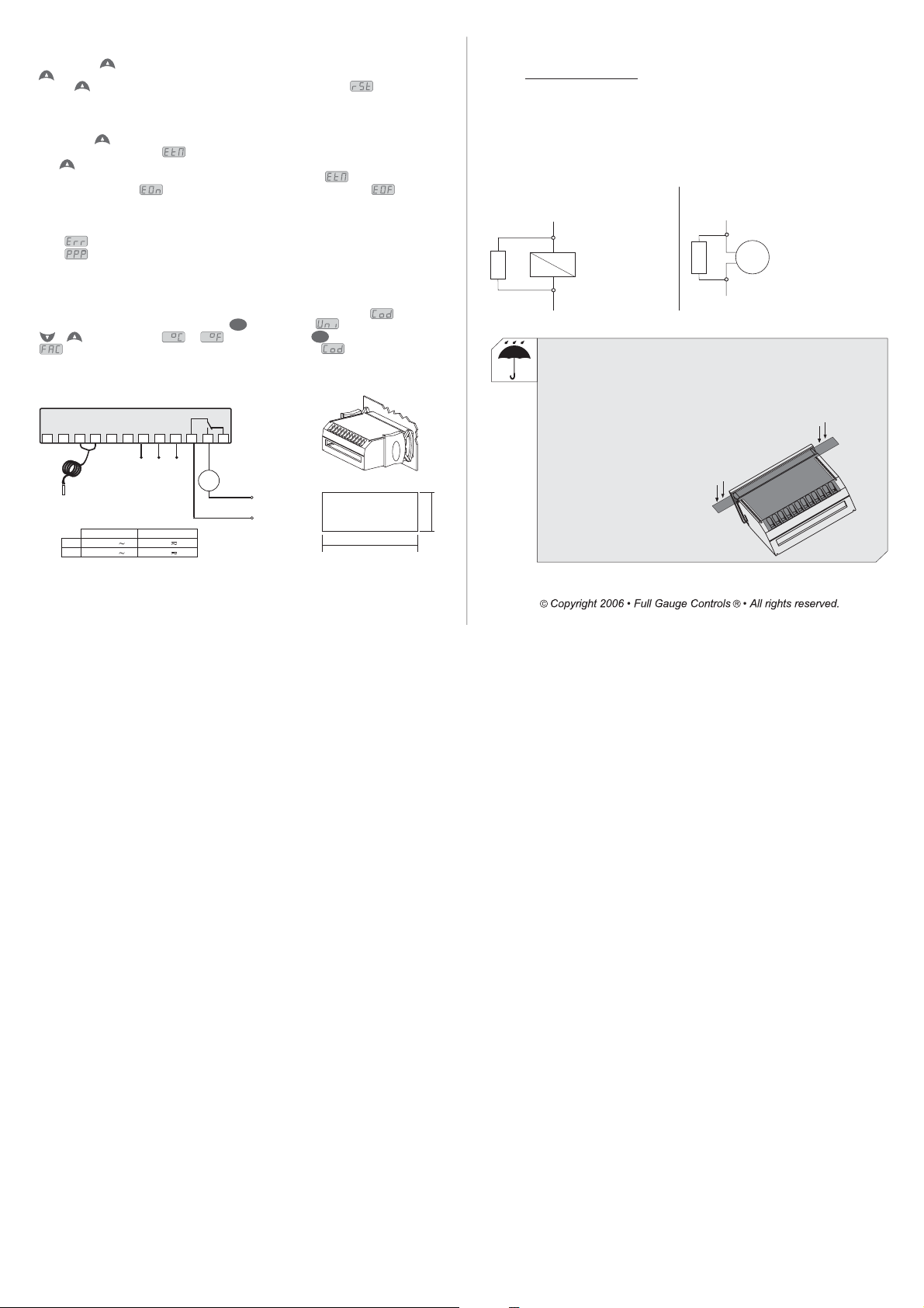
8. WIRING DIAGRAM
THERM
5
3
1
4
2
Sensor
RT-607Ri power RT-607RiLpower
7-8
115V
230V
7-9
6
7
0
Power
supply
115 V
(12 V)
8
12V
24V
230 V
(24 V)
9
11
10
12
NC
NO
COMMON
Load
Load
supply
Dimension of the clipping
for setting of the instrument
in panel
72 mm
IMPORTANT
According tothe chaptersof norm IEC60364:
1:
Install on thepower supply
protector againstovervoltage
2:
Sensor cables andsignal cables of the computer may bejoined, but not in the same electricconduit
through whichthe electricinput and theactivation ofthe loads run
3:
Install transient suppresors (RC filters) parallel to the loads as to increase the product life of the
relays.
Schematic for the connection of supresors
to contactors
A1
Suppresor
A1 and A2 are the
contactor coil terminals.
A2
Schematic for the connection of supresors to
direct activation loads
For direct activation the maximum
Load
specified current should be taken
Suppresor
into consideration.
PROTECTIVE VINYL:
This adhesive vinyl (included inside the packing) protects the instruments against
water drippings,as incommercial refrigerators, forexample.
Do theapplication afterfinishing the electricalconnections.
Remove the protective paper
and applythe vinyl onthe entire
superior part of the device,
folding theflaps asindicated by
the arrows.
29 mm
 Loading...