

Page 1
MT-543Ri plus
THREE OUTPUT DIGITAL CONTROLLER
WITH ALARM, CYCLICAL TIMER AND
SERIAL COMMUNICATION
Ver.04
E251415
MT543V04-07T-12178
1. DESCRIPTION
MT-543Ri plus has three outputs of temperature control and a internal buzzer. Because of its
versatility, it allows that the second stage works as alarm and the third, besides to work as cyclical timer,
it can work with the first stage in systems that need minimum ventilation.
Through the serial output RS-485, it permits communication with SITRAD software.
Product complies with CE (European Union) and UL Inc. (United States and Canada).
®
2. APPLICATION
• Blood banks
• Multistage temperature system
• Air conditioning
• Data centers
Note: For climatization and storage of fruits and flowers, as well as environments with condensation use
the model AHC-80 plus.
3. TECHNICAL SPECIFICATIONS
- Power Supply: MT-543Ri plus - 115/230 Vac ±10% (50/60 Hz)
- Control Temperature: NTC: -50 to 105 ºC (± 0.1ºC) / -58 to 221ºF (±1 ºF)
MT-543RiL plus - 12/24 Vac/dc
PT-100: -99 to 300 ºC (± 1 ºC) / -99 to 572ºF (±1 ºF)
- Dimensions: 71 x 28 x 71 mm
- Operating temperature: 0 to 50 ºC / 32 to 122ºF
- Operating humidity: 10 to 90% RH (without condensation)
- Load Current: 5(3)A / 250Vac 1/8HP each output
CLASSIFICATION ACCORDING TO IEC60730-2-9 STANDARD:
- Temperature limit of the installation surface: 50°C / 122ºF
- Type of construction: Built-in electronic controller
- Automatic action: Type 1
- Control of pollution: Level 2
- Impulse voltage: 1,5kV
- Temperature for the test of sphere pressure: 75°C and 125°C / 167ºF and 257ºF
- Insulation: Class II
5. PARAMETERS DESCRIPTION
F01 - Access code: 123 ( one hundred and twenty-three)
To change the parameters is necessary use the access code. It is not necessary to use the access code
to visualize the adjusted parameters.
F02 - Offset indication
It allows to compensate eventual shunting lines in the reading of ambient temperature proceeding from
the exchange of the sensor or cable lenght alteration.
F03 - Operation mode of first stage
0 - Refrigeration
1 - Heating
F04 - Minimum setpoint allowed to the end user (first stage)
F05 - Máximum setpoint allowed to the end user (first stage)
Electronic limits whose purpose is prevent that too high or too low setpoint temperatures are regulated.
F06 - Control differential (hysteresis) of first stage
It is the difference of temperature(hysteresis) between turn ON and turn OFF the OUT1 output.
F07- Minimum delay to turn on the first stage output
It is the minimum time that OUT1 will keep turned off, it means, period between the last stop and the next
start.
F08 - Operation mode of second stage
0 - Refrigeration
1 - Heating
2 - Intra-range alarm (F09 and F10)
3 - Extra-range alarm (F09 and F10)
4 - Relative extra-range to first stage ( - F09 and + F10), It is considered the absolute
values of F09 and F10).
F09 - Minimum setpoint allowed to the end user (second stage)
F10 - Maximum setpoint allowed to the end user (second stage)
Electronic limits whose purpose is prevent that too high or too low setpoint temperatures are regulated.
When the second stage ( F08 ) is defined as alarm, the acting points are defined in F09 and F10.
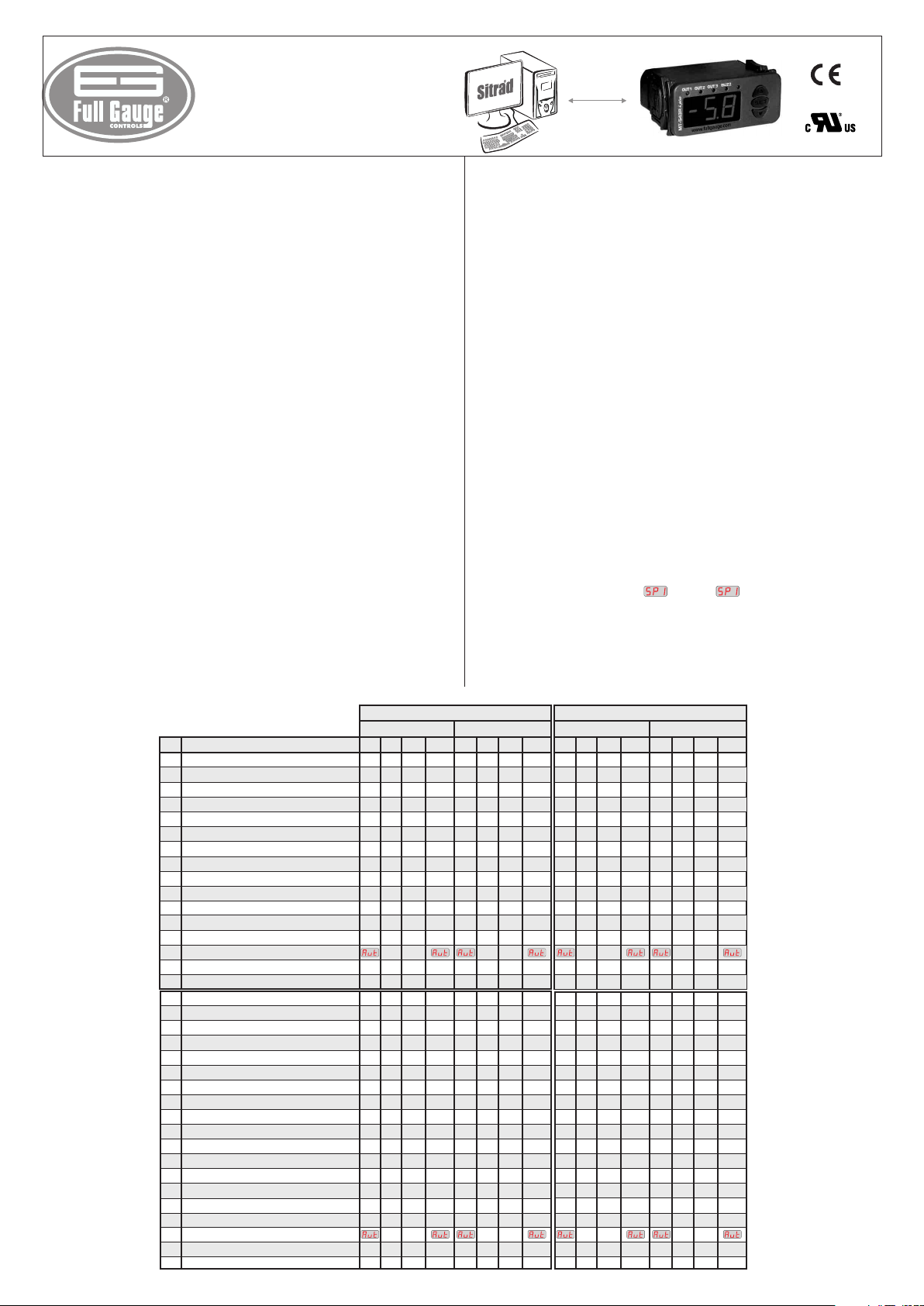
4. PARAMETERS TABLE
F01
Access code:123(one hundred and twenty-three)
F02
Offset indication
F03
Operation mode of first stage
F04
Minimum setpoint allowed to the end user (first stage)
F05
Maximum setpoint allowed to the end user (first stage)
F06
Control differential (hysteresis) of first stage
F07
Minimum delay to turn on the first stage output
F08
Operation mode of second stage
F09
Minimum setpoint allowed to the end user (second stage)
F10
Maximum setpoint allowed to the end user (second stage)
F11
Control differential(hysteresis) of second stage
F12
Minimum delay to turn on the second stage output
F13
Delay to enable the alarm when the instrument is powered on
F14
Reactivation time of alarm when inhibited manually
F15
Alarm Time (on cycle)
Alarm Time (off cycle)
F16
F17
Operation mode of third stage
Minimum setpoint allowed to the end user (third stage)
F18
Maximum setpoint allowed to the end user (third stage)
F19
Control differential (hysteresis) of third stage
F20
Minimum delay to turn on the third stage
F21
Time base of third stage cyclical timer
F22
Activation time for third stage cyclical timer
F23
Cyclical timer on third stage- time on
F24
Cyclical timer on third stage- time off
F25
Operation mode of cyclical timer
F26
Operation mode of Buzzer
F27
Acting point of Buzzer (inferior limit)
F28
Acting point of Buzzer (superior limit)
F29
Buzzer time on
F30
Buzzer time off
F31
Inhibition time of Buzzer during electrical supply
F32
Reactivation time of Buzzer when inhibited manually
F33
Intensity of the digital filter
F34
Network equipment address RS - 485
F35
DescriptionFun
Min
-5.0
-50
-50
0.1
-50
-50
0.1
-50
-50
0.1
-50
-50
NTC
CELSIUS
Unit
Max
Standard
-
-
°C
5.0
-
1
0
°C
105
105
20.0
999
0
0
105
105
20.0
999
0
999
0
999
999
0
999
0
0
2
105
105
20.0
0
999
0
1
999
0
999
0
999
0
4
0
2
0
105
105
999
0
999
0
999
0
999
9
0
247
1
-50
°C
105
°C
1.0
sec.
-
4
ºC
21.0
ºC
27.0
ºC
1.0
sec.
min.
min.
sec.
sec.
0
-
-50
ºC
105
ºC
1.0
ºC
0
sec.
0
-
5
sec.
0
-
0
-
0
-
1
-
ºC
-50
ºC
105
sec.
1
sec.
1
min.
0
min.
-
0
-
1
FAHRENHEIT
Unit
Max
221
221
999
999
999
999
221
221
999
999
999
999
247
221
221
999
221
221
999
999
999
999
999
Standard
-
sec.
sec.
min.
min.
sec.
sec.
sec.
sec.
sec.
sec.
min.
min.
-
°F
0
-
1
°F
-58
°F
221
°F
2
0
-
3
ºF
70
ºF
81
ºF
2
0
0
1
1
-
0
ºF
-58
ºF
221
ºF
2
0
-
0
5
-
0
-
0
-
0
-
1
ºF
-58
ºF
221
1
1
0
-
0
-
1
-
9
1
36
4
36
2
36
1
4
2
9
Min
-
-
0
-9
1
0
-58
-58
1
0
0
3
0
-58
-58
1
0
0
0
0
1
0
1
0
0
-58
-58
1
0
0
0
0
0
0
0
-58
-58
0
0
0
0
1
Min
-50
-99
-99
-99
-99
-99
-99
-99
-99
CELSIUS
Max
-
-
50
0
1
300
300
1
40
0
999
0
4
300
300
1
40
0
999
0
999
999
0
999
0
999
0
2
300
300
1
40
0
999
0
1
0
999
0
999
0
999
0
4
0
2
300
300
0
999
0
999
0
999
999
0
9
1
247
Unit
°C
°C
°C
°C
sec.
ºC
ºC
ºC
sec.
min.
min.
sec.
sec.
ºC
ºC
ºC
sec.
sec.
ºC
ºC
sec.
sec.
min.
min.
-
-
-
-
-
-
-
-
-
-
-
PT-100
Standard
-
0
1
-99
300
2
0
3
21
27
2
0
0
1
1
0
-99
300
2
0
0
5
0
0
0
1
-99
300
1
1
0
0
1
Min
-
-90
0
-99
-99
1
0
0
-99
-99
1
0
0
0
0
0
-99
-99
1
0
0
0
0
0
0
0
-99
-99
0
0
0
0
1
FAHRENHEIT
Unit
Max
-
-
°F
90
-
1
°F
572
°F
572
°F
72
sec.
999
-
4
ºF
572
ºF
572
ºF
72
sec.
999
min.
999
min.
999
sec.
999
sec.
999
-
2
ºF
572
ºF
572
ºF
72
sec.
999
-
1
sec.
999
-
999
-
999
-
4
-
2
ºF
572
ºF
572
sec.
999
sec.
999
min.
999
min.
999
-
9
-
247
Standard
-
0
1
-99
572
4
0
3
70
81
4
0
0
1
1
0
-99
572
4
0
0
5
0
0
0
1
-99
572
1
1
0
0
1
Page 2
F11 - Control differential(hysteresis) of second stage
It is the difference of temperature(hysteresis) between turn ON and turn OFF the output OUT2.
F12- Minimum delay to turn on the second stage output
It is the minimum time that the output OUT2 will keep turned off, it means, the space of time between the
last stop ant the next start. Only if programmed in F08 = 0 or 1.
F13 - Delay to enable the alarm when the instrument is powered on
During this time the alarm is kept turned off waiting that the system reaches the working control
temperature (only if F08 is set as alarm).
F14 -Reactivation time of alarm when inhibited manually
This function allows three different settings(only if F08 is set as alarm):
- The alarm is inhibited by an indefinite period or until the temperature range in normal
working condition and return the alarm again;
0 - The alarm can not be inhibited by facilitating access keys;
1 to 999 - The alarm will be inhibited during this period (in minutes), returning the call if the alarm
condition persists;
F15 - Alarm time (on cycle)
It allows to adust the time that OUT2 output will keep turned on (only if F08 is set as alarm).
F16 - Alarm time (off cycle)
It allows to adust the time that OUT2 output will keep turned off(only if F08 is set as alarm). To keep the
alarm always activated just set “0” in this function.
F17 - Operation mode of third stage
0 - Refrigeration
1 - Heating
2 - Cyclical Timer
F18 - Minimum setpoint allowed to the end user (third stage)
F19 - Maximum setpoint allowed to the end user (third stage)
Electronic limits whose purpose is prevent that too high or too low setpoint temperatures are regulated.
F20 - Control differential (hysteresis) of third stage
It is the difference temperature (hysteresis) between turn ON and turn OFF the output OUT3.
F21- Minimum delay to turn on the third stage
It is the minimum time that the output OUT3 will keep turned off, it means, the space of time between the
last stop and the next start. Only if programmed in F17 = 0 or 1.
F22-Time base of third stage cyclical timer
0 - seconds
1 - minutes
F23 - Activation time of third stage cyclical timer
This function depends of F26. Every time that the temperature reach the configured value in , the
configured time in this function is respected, to be activated the cyclical timer after. To activate the timer
when is reached just set “0” in this function.
F24 - Cyclical timer on trird stage- time on
It is the time that the timer will be turned on.
F25 - Cyclical timer on trird stage- time off
It is the time that the timer will be turned off.
F26 - Operation mode of cyclical timer
0 - Independent timer
1 - Timer started by the first stage setpoint
2 - First stage linked with cyclical timer (Timer starts on)
3 - First stage linked with cyclical timer (Timer starts off)
4 - Cyclical timer output turned on whenever the the first stage output is turned on
F27 -Operation mode of Buzzer
0 - Intra-range alarm (F28 and F29)
1 - Extra-range alarm (F28 and F29)
2 - Relative extra-range to first stage ( - F28 and + F29), It is considered the absolute
values of F28 and F29).
F28 - Acting point of Buzzer (inferior limit)
It is the inferior value of temperature to the buzzer alarm act as the configured Operation Mode of Buzzer
(F27).
F29 - Acting point of Buzzer (superior limit)
It is the superior value of temperature to the buzzer alarm act as the configured Operation Mode of
Buzzer (F27)
F30 - Buzzer time on
It is the time that the Buzzer will be turned on (cycle on). To turn it off the sonore alarm (Buzzer) adjust the
value “0” to this function.
F31 - Buzzer time off
It is the time that the buzzer will be turned off (cycle off). To turn it off the sonore alarm (Buzzer) adjust the
value “0” to this function.
F32 - Inhibition time of Buzzer during electrical supply
It is the time were the Buzzer will kept turned off even if in alarm contitions for a certain period after
startup, because the system has not yet reached working temperature.
F33 -Reactivation time of Buzzer when inhibited manually
This function allows three different settings:
- The Buzzer is inhibited by an indefinite period or until the temperature range in normal
working condition and return the alarm again;
0 - The Buzzer can not be inhibited by facilitating access keys;
1 to 999 - The Buzzer will be inhibited during this period (in minutes), returning the call if the alarm
condition persists;
Intensity of the digital filter
F34 -
This filter aims at simulating an increase of the mass of sensor , thus increasing its response time
(thermal inertia). The larger the value adjusted in this function, the longest the response time of sensor.
A typical application requiring this filter is the freezer for ice cream or frozen goods, because when the
door is opened a hot air mass reaches the sensor directly, causing the indication of the measured
temperature to rise quickly and the compressor to be activated
F35 - Network equipment address RS - 485
Each controller connected to the RS-485 network must have its own address different from the others so
that the computer will be able to identify it.
Attention: To avoid communication problems, make sure that there are no controllers with the same
address.
6. CONFIGURATIONS
6.1 - Control temperature adjust (SETPOINT)
SET
- Press for 2 seconds until appears ,then release it.
will appear and the temperature will be adjusted for the first stage.
- Use and to change the value and, when ready, press .
- Adjust in the same way (2nd estage) and (3rd stage).
SET
7. PARAMETERS ALTERATION
- Access function “F01” by simultaneously pressing keys and for 2 seconds.
When the message appears release the keys and wait for the indication. When the
indication appears on the display press the key and use and to enter the access code
(123) When ready press the button to confirm.
- Use keys and to access the desired function.
- After selecting the function, press (press once quickly) to view the value configured for that
function.
- Use the and keys to change the value and, when ready, press to memorize the
configured value and return to the function menu.
- To exit the menu and return to the normal operation (temperature indication), press (hold it in)
until appears.
SET
SET
SET
SET
SET
8. FUNCTIONS WITH FACILITATED ACCESS
8.1 Register of minimum and maximum temperatures
Press , appear the minimum registered temperatures. Soon will apears the the maximum registered
temperature.
Note: To reset the registers, keep the key pressed during the visualization of minimum and maximum
registers until to be showed.
8.2 Alarm and Buzzer inhibition
To inhibit the OUT2 press the and keys simultaneously .
To inhibit the Buzzer press the and keys simultaneously.
SET
SET
9. SIGNALING
OUT 1 - Output 1 turn on
OUT 2 - Output 2 turn on
OUT 3 - Output 3 turn on
BUZZ - Buzzer activated
- Detached temperature sensor or outside the specified range
10. SELECTION OF THE UNIT (ºC / ºF)
In order to define the unit that the instrument will operate in, enter function “F01” with the access code
231 and confirm with the key. Press the key and the indication will appear.
SET
Press to choose between or and confirm. After selecting the unit the message
SET
will appear, and the instrument will return to the function “F01”. Every time that the unit is changed, the
parameters should be reconfigured, since they assume the “standard” values.
11. SELECTION OF THE SENSOR TYPE
F01 - Access code (312)
It is necessary when it is desired to select the sensor type.
After entering the code 312, use to confirm. Access the function and select between for
SET
NTC thermistor or for PT100 sensor.
Everytime that a new sensor is selected the parameters must be adjusted.
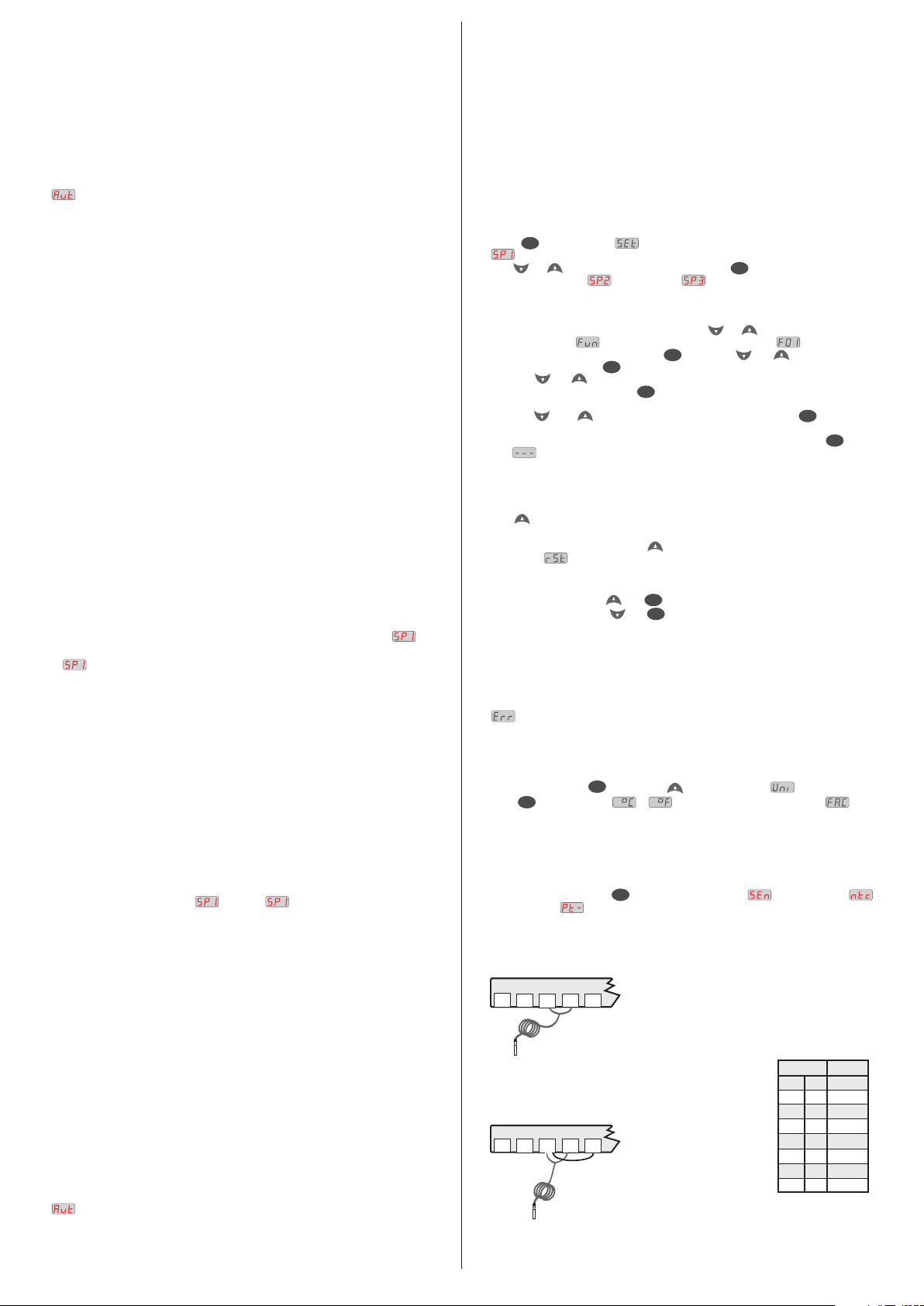
11.1 - NTC SENSOR
It must be connected to the terminals 3 and 4, as showed below:
1
1
NTC sensor
11.2 - PT-100 SENSOR
It must be connected to the terminals 3 and 4 and with the terminals
3 and 5 interconnected, as showed below:
1
212
212
212
PT-100 sensor
4
4
5
5
3
3
* Sensor supplied with the controller.
4
5
3
* Sensor not supplied with the controller.
Table of relation, wire
gauge/maximum distance for
two wires PT-100.
Diameter
Max. Dist.
(meters)
(mm)
(AWG)
14
1.63
1.29
1.02
0.81
0.64
0.51
0.40
18.1
11.4
7.2
3.0
1.9
1.8
1.1
16
18
20
22
24
26
Page 3

12. WIRING DIAGRAM
5
4
21 21 3
A
B
Sensor
RS-485
To the terminal of
the onnecting blockc
Serial communication
MT-543Ri plus MT-543RiL plus
6 - 7
115V
230V
6 - 8
6
0
7
115V
(12V )
Power
supply
12V
24V
8
230V
(24V )
9
11
10
12
OUT 1
OUT 2
COMMON
C1
OUT 3
C3
C2
supply
Over the specifield current
use a contactor.
LOADS
Load
Note: The length of the sensor cable may be increased by the user up to 200 meters, using a PP
2 x 24 AWG cable. For immersion in water, use thermometric well.
Integrating Controllers, RS-485 Serial Interface and Computer
IMPORTANT
According to the chapters of norm IEC 60364:
1: Install protector against overvoltage on the power supply
2: Sensor cables and signal cables of the computer may be joined, but not in the same electric conduit
through which the electric input and the activation of the loads run
3: Install transient suppresors (RC filters) parallel to the loads as to increase the product life of the
relays.
Schematic for the connection of supresors
to contactors
A1
Suppresor
A1 and A2 are the
contactor coil terminals.
A2
Schematic for the connection of supresors to
direct activation loads
For direct activation the maximum
Load
specified current should be taken
Suppresor
into consideration.
®
Keep Sitrad updated in website:
http://www.sitrad.com
A
A
B B
A B
*Connecting Block for Serial Communication
Used to connect more than one instrument to the Interface. The wire's connections must
be made in agreement with the following rules: terminal A of the instrument connects to
the terminal A of the c , that must be connected with the terminal A of the
Interface. Repeat the action for terminals B and , being the cable shield.
the terminal of distribution box must be connected to the respective terminals of
each instrument.
*Sold Separately
A
B B
B
1
OUT 4
ALMR
OUT
OUT 2
OUT 3
PCT-400R plus
onnecting block
A
AB
A
A
B B
B
A
AB
A
A
A
B B
AB
A
B
1
PUMP
AUX
AUX 2
MICROSOL II plus
A
B B
PROTECTIVE :VINYL
This adhesive vinyl (included inside the packing) protects the instruments against
water drippings, as in commercial refrigerators, for example. Do the application after
finishing the electrical connections.
Remove the protective paper
and apply the vinyl on the entire
A
AB
superior part of the device,
folding the flaps as indicated by
the arrows.
Dimension of the clipping
for setting of the instrument
in panel
72 mm
29 mm
 Loading...