

Page 1
1. DESCRIPTION
The
®
.
MT-530e %uper has three outputs: one for temperature control, one for humidity control and a
third auxiliary output that acts as a second stage temperature control, humidity control, alarm or timer
cyclical.
This controller is indicated for low and medium relative humidity (10-85% non-condensing). Its
temperature sensors and humidity are united in a single bulb, reducing installation space and wiring. It
also includes an audible alarm (buzzer) and an intelligent system locking functions, preventing
unauthorized people from changing the control parameters.
The instrument features a serial communication for connection to Sitrad
Product complies with UL Inc. (United States and Canada).
2. APPLICATION
3. TECHNICAL SPECIFICATIONS
• Humidifiers / dehumidifiers
• Grains drying
• Laboratories
• Surgical rooms
• Climatized cellars
• Information technology centers
*For high percentage of humidity in the presence of water condensation, use the model AHC-80 Ri
plus.
- Power Supply: MT-530E Super 115 or 230 Vac ±10%(50/60 Hz)
MT-530EL Super 12 or 24 Vac/dc ±10%
- Control Temperature: -10 to 70.0 ºC ±1.5°C (with resolution of 0.1°C)
14 to 158 ºF ±3°F (with resolution of 1°F)
- Operation temperature: 0 to 50°C
32 to 122°F
- Control Humidity: 10 to 85%RH ±5%RH (with resolution of 0.1%RH)
- Operation humidity: 10 to 85% RH (without condensation)
- Load current: Therm : 16(8)A/250Vac 1HP
Humid : 5(3)A/250Vac 1/8HP
Aux : 5(3)A/250Vac 1/8HP
- Dimensions: 76 x 34 x 77 mm
→
→
(WxHxD)
- Dimensions of the clipping for fixing of the instrument: 71 ± 0,5 x 29 ± 0,5 mm (see item 5)
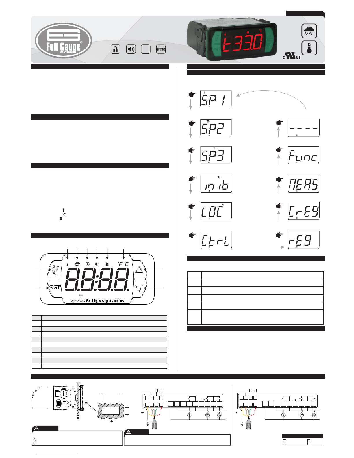
4. INDICATIONS AND KEYS
Key Set
Menu key facility
Therm output led indicator
Humidity output led indicator
Aux output led indicator
Buzzer output led indicator
Lock functions led indicator
Temperature unit led indicator
Upper key
Lower key
1
2
3
4
5
6
7
8
9
10
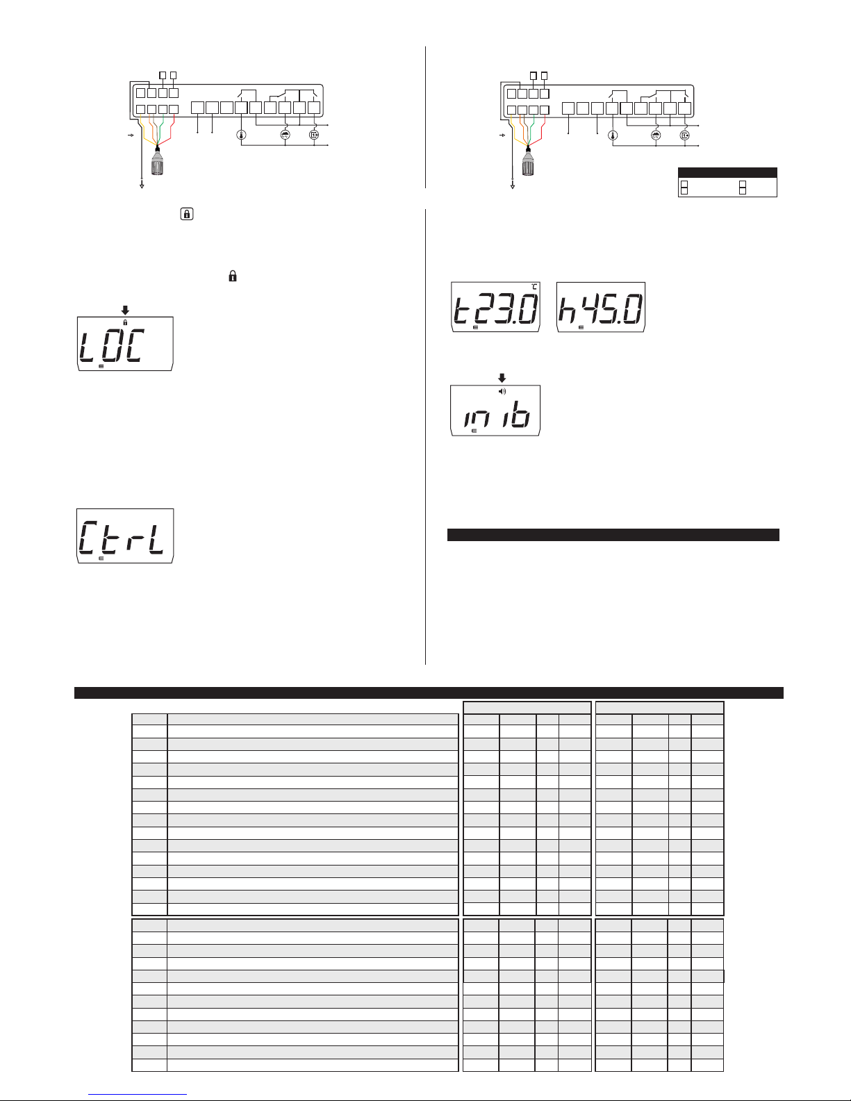
5. INSTALLATION - ELECTRICAL CONNECTIONS AND PANEL
6. OPERATIONS
6.1 Facilitated menu map
By pressing the button , it is possible to navigate through the function menus. See the map functions
below:
;
6.2 FACILITATED KEY MAP
When the controller is on display temperature, the following shortcut keys are used for the following
functions:
/
<
<
<
<
Press 2 sec: Adjust setpoint.
Short press: Switch display of temperature or humidity for 4s.
Short press: Display of records minimum and maximum measures.
Enter the function selection.
Panel (Front View)
Panel
(Side View)
Connection 115 Vac Connection 230 Vac
6.3 BASIC OPERATIONS
6.3.1 Adjusting the temperature and humidity (setpoint)
To enter the setup menu press the setpoints / for 2 seconds. The message "[Sp1,]" will appear on
the display then the value of the setpoint output Therm adjustment. Use <and> keys to modify the
value and confirm by pressing /.Then the message "[SP2,]" will appear indicating the adjustment
of setpoint output Humid. Again use the <and>keys to modify the value and confirm by pressing/.
If the operating mode for the Aux output require setting a setpoint the message "[SP3,]" will appear
and it can be adjusted the same way is the previous ones. At the end the message "[----]
indicating setup completion. The setpoints can also be adjusted individually on the facilitated
menu.
desired
" will
appear
5
43
2
9
8
7
6
1
10
MT-530 %uper
<
<
Press 2 sec: When the buzzer is active inhibits the alarm.
Press 2 sec: When the record is displayed, clear the history.
* These parameters are displayed when necessary.
DIGITAL CONTROLLER AND INDICATOR
OF TEMPERATURE AND HUMIDITY
WITH SERIAL COMMUNICATION TO SITRAD
Functions
lockdown
Protection
level
Buzzer System
supervisor
evolution
1
2
3
4
Yellow
Orange/Brown
Green
Red
LEGEND
;
SETPOINT OUTPUT THERM
;
SETPOINT OUTPUT HUMID
;
SETPOINT OUTPUT AUX*
INHIBITOR BUZZER*
;
SELECTION FUNCTION
;
ALTERNATE VIEWING MEASURE
;
CLEAR VALUES MAX. AND MÍN.
;
;
LOCK FUNCTION
REGISTRATION OF
TEMPERATURE MÍN. AND MÁX.
;
;
CONTROL FUNCTIONS
SHUTDOWN
EXIT THE MENU
;
IP 65
FRONT
MT530ESV04-03T-13899
1
5
678
2
3
4
9
POWER
SUPPLY
10
11 121314
15 16
17
THERM
HUMID
AUX
A B
RS - 485
115 Vac
To the terminal of
the distribution box
1
5
678
2
3
4
9
POWER
SUPPLY
10
11 121314
15 16
17
THERM
HUMID
AUX
A B
RS - 485
230 Vac
71 mm± 0,5
29 mm± 0,5
Dimension of the clipping
for setting of the
instrument in panel
MT-530
e
%uper
MT-530
e
%uper
V
er
.04
MT-530 %uper e
MT-530
%uper
MT-530
%uper
MT-530
%uper
MT-530
%uper
MT-530
%uper
MT-530
%uper
MT-530
%uper
MT-530
%uper
MT-530
%uper
MT-530
%uper
MT-530
%uper
FOR INSTALLATIONS WHERE A SEALING IS REQUIRED TO AVOID LIQUID CONTACT, THE CUT FOR THE
CONTROLLER MUST BE OF 70,5X29mm MAXIMUM. THE SIDE LOCKS MUST BE FIXED SO IT PRESSES
THE RUBBER SEALING AVOIDING INFILTRATION BETWEEN THE CUT AND THE CONTROLLER.
ATTENTION
SCREWDRIVER SLOT 3/32''(2.4mm) FOR ADJUSTMENTS IN THE SIGNAL TERMINALS;
SCREWDRIVER PHILLIPS #1 FOR ADJUSTMENTS IN THE POWER TERMINALS;
IMPORTANT
THE USE OF APPROPRIATE TOOLS IS ESSENTIAL TO AVOID DAMAGE IN THE
CONNECTION AT INSTRUMENT TERMINALS:
To the terminal of
the distribution box
E251415
Page 2
7.2 Parameter table
6.3.2 Function Lock
To unlock, turn off the controller and reconnect it with the key> pressed. Keep the key pressed until
the message [LOC,] appears, them release and [OFF,]will appear on the display.
6.3.3 Control Functions Shutdown
6.3.4 Registers of minimum and maximum measures
Pressing key < or also through the quick access menu (see chapter 6), the message [rEg,] will
appear, followed by the minimum and maximum recorded temperatures.
For safety reasons, this controller provides the ability to lock functions. With this setting enabled, the
setpoint and the other parameters are protected against undue changes however, they can be viewed.
In this condition, when trying to change these values the message [LOC,] will appear on the display.
To perform the lock function is necessary, first, that the parameter "[,F42] - Time lock function" is
set to the value exceeding 14 (below the value 15, it is shown[no,,]is not allowing the blocking of
functions). With the key ;(short press), select ,then press / (short press), after hold the key>
until [LOC,](time in seconds programmed in [,F42]). When you release the key the message
[On,,]will appear on the display.
With the shutdown of the control functions the controller will operate only as a temperature and humidity
indicator and the output relays stays off.
The way to operate the control functions shutdown depends on the parameter setting “[,F43]Control functions shutdown”:
[,,,0]Does not allow the shutdown of the control functions.
[,,,1]Allows to turn on and off the control functions only if the functions are unlocked.
[,,,2]Allows to turn on and off the control functions even when the functions are locked.
With key ;(quick touch), select [Ctrl], then press /(quick touch) to confirm.
Then, the message [ctrl][Off,] will appear. At this time the temperature display will switch to
the [OFF,] message.
To turn the control functions on again, just follow the same procedure as that for shutdown, selecting
with the ; key (quick touch). Once the user presses the / key the message [ctrl][On,,] will
ap p e a r .
6.3.7 Unit Selection (ºC / ºF)
“[,F01]”
[,231] / then the user can select the unit by pressing the keys
<and>where there are alternating messages [,=C,]or[,=F,]. Press the key/to confirm the
desired unit. Therefore, the corresponding indication unit {or} will be turned on.Every time the unit is
changed, the parameters must be reconfigured, since they assume the "standard" values.
In order to define the unit that the instrument will operate in, enter function with the access
code and confirm with the key.
7. ADVANCED OPERATIONS
7.1 Changing the parameters of the controller
Access function [,F01] by pressing keys <and> simultaneously or through the quick access
menu. After that, [,F01] will appear, then, press the/ key (short press). Use keys <or >to enter
with access code [,123] and, when ready, press /. Use keys <or> to access the desired
function. After selecting the function, press the key/ (short press), to visualize the set value for that
function. Use keys <or> to change the value, and when ready, press/ to memorize the set value
and return to the functions menu. To exit the menu and return to normal operation (temperature
indication) press/(long press) until [----]appears on the display.
Obs: If the lock function is active, by pressing the <or> to change the value of the function, the
controller will displays the message [LOC,] and will not allow to set the of parameter.
DescriptionFun
Access code: 123 (one hundred and twenty-three)
Thermostat operation mode (THERM output)
Minimum setpoint allowed to the end user (thermostat)
Maximum setpoint allowed to the end user (thermostat)
Control differential (hysteresis) of the thermostat
Minimum delay to turn the thermostat output on
Humidistat operation mode (HUMID output)
Minimum setpoint allowed to the end user (humidistat)
Maximum setpoint allowed to the end user (humidistat)
Control differential (hysteresis) of the humidistat
Minimum delay to turn the humidistat output on
Humidity output (time on)
Humidity output (time off)
Auxiliary output operation mode (AUX)
Minimum setpoint allowed to the end user (AUX output)
CELSIUS
FAHRENHEIT
Min.
-99
0 - refrig.
-10.0
-10.0
0.1
no
0 - dehum.
0
0
0.1
no
0
0
0
0
Max.
999
1 - heat
70.0
70.0
20.0
999
1 - humid.
100
100
20.0
999
999
999
10
100
Unit
-
-
°C
°C
°C
seg.
-
%RH
%RH
%RH
sec.
sec.
sec.
-
-
Standard
-
0 - refrig.
-10.0
70.0
1.5
no
1 - humid.
0
100
5
no
5
5
5
0
Min.
-99
0 - refrig.
14
14
1
no
0 - dehum.
0
0
0.1
no
0
0
0
0
Max.
999
1 - heat
158
158
36
999
1 - humid.
100
100
20.0
999
999
999
10
100
Unit
-
-
°F
°F
°F
seg.
-
%RH
%RH
%RH
sec.
sec.
sec.
-
-
Standard
-
0 - refrig.
14
158
3
no
1 - humid.
0
100
5
no
5
5
5
0
[,F01]
[,F02]
[,F03]
[,F04]
[,F05]
[,F06]
[,F07]
[,F08]
[,F09]
[,F10]
[,F11]
[,F12]
[,F13]
[,F14]
[,F15]
6.3.5 To visualize humidity or temperature
It is possible to view the other measure (humidity or temperature) by pressing >.
6.3.6 Buzzer Inhibit
When buzzer starts it can be inhibited by pressing > for two seconds or by quick access menu.
Indication:
- '' T'' temperature record
- '' H'' record humidity
To turn the current minimum and maximum values off, press key ;(short press) repeatedly, until the
message [CrEg] is displayed, finally press the / button to confirm. Another way is to press<2
seconds while displaying the records. This operation is indicated by the message [RSET].
1
5
678
2
3
4
9
POWER
SUPPLY
10
11 121314
15 16
17
THERM
HUMID
AUX
A B
RS - 485
Connection Vac/dc 24
1
5
678
2
3
4
9
POWER
SUPPLY
10
11 121314
15 16
17
THERM
HUMID
AUX
A B
RS - 485
Loads supply
Connection 12 Vac/dc
1
2
3
4
Yellow
Orange/Brown
Green
Red
LEGEND
To the terminal
of the distribution box
To the terminal
of the distribution box
Maximum setpoint allowed to the end user (AUX output)
Control differential (hysteresis) of the AUX output
Minimum delay to turn the AUX output on
Time base of AUX output timer
AUX output (time on)
AUX output (time off)
Low room temperature alarm
High room temperature alarm
Low room humidity alarm
High room humidity alarm
Minimum delay to turn the AUX output on (alarm mode)
Buzzer operation mode
0
0.1
no
0
0
0
-10.0
-10.0
0
0
0
0
100
20.0
999
999
999
999
70.0
70.0
100
100
999
1
-
-
sec.
-
sec.
sec.
°C
°C
%RH
%RH
min.
-
100
5
no
0
5
5
-10.0
70.0
0
100
0
1
0
0.1
no
0
0
0
14
14
0
0
0
0
100
20.0
999
999
999
999
158
158
100
100
999
1
100
5
no
0
5
5
14
158
0
100
0
1
-
-
sec.
-
sec.
sec.
°F
°F
%RH
%RH
min.
-
[,F16]
[,F17]
[,F18]
[,F19]
[,F20]
[,F21]
[,F22]
[,F23]
[,F24]
[,F25]
[,F26]
[,F27]
12 Vac/dc
24 Vac/dc
Loads supply
MT-530
%uper
MT-530
%uper
MT-530
%uper
MT-530
%uper
MT-530
%uper
Page 3

Time to lock functions
Control functions shutdown
Network equipment address RS-485
no
no
1
60
2
247
sec.
-
-
no
no
1
no
no
1
60
2
247
no
no
1
sec.
-
-
[,F42]
[,f43]
[,F44]
F09 - Maximum setpoint allowed to the user (humidistat):
Electronic limits whose purpose is to prevent too high or too low setpoint humiditys are set.
F10 - Control differential (hysteresis) of the humidistat:
It is the difference of humidity (hysteresis) between turn ON and turn OFF the HUMID output.
It is the minimum time that the HUMID output will keep turned off, it means, the space of time between
the last stop and the next start.
It allows to adjust the time that HUMID output will keep turned on.
It allows to adjust the time that HUMID output will keep turned off.
[,f12] and [,f13]
F11 - M
F12 -
F13 -
,,,0]
[,,,1]
[,,,2]
[,,,3]
[,,,4]
[,,,5]
[,,,6]
[,,,7]
[,,,8]
[,,,9]
[,,10]
[,f15] [,f16] [,f17]
inimum delay to turn the humidistat output on:
Humidity output (time on):
Humidity output (time off):
Note: functions control a cyclical program (in seconds) for the humidistat output. This
cyclical program allows that pulverized water has time to transform in relative air humidity.
To disable this function, adjust the values to zero.
F14 - Auxiliary output operation mode (AUX):
[ Refrigeration
Heating
Dehumidification
Humidification
Intra-range alarm
Extra-range alarm
Independent cyclic timer
Cyclic timer operating only when the temperature reaches the setpoint (THERM output
deactivated)
Cyclic timer operating only when the humidity reaches the setpoint (HUMID output
deactivated)
Cyclic timer operating when the temperature or humidity reaches their setpoint
Cyclic timer operating only when the temperature and humidity reaches their setpoints
When changing the value of this function the following parameters will be automatically adjusted with
their default values: , , and setpoint for the AUX output.
F15 - Minimum setpoint allowed to the user (AUX output):
F16 - Maximum setpoint allowed to the user (AUX output):
Electronic limits whose purpose is to prevent that too high or too low setpoint values are set.
The limits will depend on the operation mode of the output adjusted in .
F17 - Control differential (hysteresis) of the AUX output:
It is the difference of temperature or humidity (hysteresis) between turn ON and turn OFF the AUX
output. This function depends on the operation mode of the output adjusted in .
F18 - Minimum delay to turn the AUX output on:
It is the minimum time that the AUX output will keep turned off, it means, the space of time between the
last stop and the next start.
Time base of AUX output timer:
Allows configuration of the on or off time scale for AUX output cyclic timer.
[,f14]
[,f14]
This time is valid only when AUX output is configured in the control mode
([,f14] configured in 0, 1, 2 or 3).
F19 -
F22 - Low room temperature alarm:
Temperature for activation of the low temperature alarm.
F23 - High room temperature alarm:
Temperature for activation of the high temperature alarm.
F24 - Low room humidity alarm:
Humidity for activation of the low humidity alarm.
F25 - High room humidity alarm:
Humidity for activation of the high humidity alarm.
F26 - Minimum delay to turn the AUX output on (alarm mode):
It is the minimum time that the AUX output will keep turned off after controller initialization. This time is
valid only when AUX output will be configured in the alarm mode ([,F14] configured in 4 or 5).
F27 - Buzzer operation mode:
Intra-range alarm
Extra-range alarm
[,,,0]
[,,,1]
F28 - Acting point of Buzzer by low temperature:
It is the minimun temperature to trigger the buzzer the configured Operation Mode of Buzzer [,F27].
F29 - Acting point of Buzzer by high temperature:
It is the superior value of temperature to the buzzer alarm act as the configured Operation Mode of
Buzzer [,F27].
F30 - Acting point of Buzzer by low humidity:
It is the inferior value of humidity to the buzzer alarm act as the configured Operation Mode of Buzzer
[,F27].
Acting point of Buzzer by high humidity:
[,F27]
F31 -
It is the superior value of humidity to the buzzer alarm act as the configured Operation Mode of Buzzer
.
F32 - Maximum time of the activated THERM output to activate the alarm:
Allows configuring the maximum time the output THERM can stay activated without reaching the
setpoint before activating the audible alarm (BUZZER). To deactivate this function, just decrement the
value until the message is displayed
Maximum time of the activated HUMID output to activate the alarm:
Allows configuring the maximum time the output HUMID can stay activated without reaching the setpoint
before activating the audible alarm (BUZZER). To deactivate this function, just decrement the value until
the message is displayed.
F34 - Maximum time of the activated AUX output to activate the alarm:
Allows configuring the maximum time the output AUX can stay activated without reaching the setpoint
before activating the audible alarm (BUZZER). To deactivate this function, just decrement the value until
the message is displayed.
F35 -Buzzer time on:
It is the time that the Buzzer will be turned on (cycle on). To turn it off the sonore alarm (Buzzer) adjust the
value “0” to this function.
F36 - Buzzer time off:
It is the time that the buzzer will be turned off (cycle off). To turn the sonore alarm (Buzzer) always on,
adjust the value “0” to this function.
F37 - Inhibition time of Buzzer during electrical supply:
It is the time were the alarm will kept turned off even if in alarm contitions.
It serves to inhibit the buzzer during the time while the system do not reaches the working control
temperature.
F38 - Output status in case of alarm:
Status output do not change in case of alarm
Turn off the output THERM, HUMID and AUX;
Note: The AUX output will not turn off if it is set to alarm output intra-or-extra range. In case of sensor
failure the outputs will be switched off independently of the parameter settled in that function.
[no,,] .
F33 -
[no,,]
[,,,0] ;
[,,,1]
[no,,]
F20 - AUX output (time on):
It is the time that AUX output will keep turned on when set to alarm or cyclical timer. See [,f14]
F21 - AUX output (time off):
It is the time that AUX output will keep turned off when set to alarm or cyclical timer. See [,f14].
F01 -
It is required for changing the configuration parameters. To visualize the adjusted parameters, it is not
necessary to insert this access code.
F02 -
[,,,0]Refrigeration
[,,,1]Heating
F03 - Minimum setpoint allowed to the end user (t
F04 - Maximum setpoint allowed to the end user (thermostat):
To prevent incorrect temperature setting.
F05 - Control differential (hysteresis) of the thermostat:
It is the difference of temperature (hysteresis) between ON and OFF the THERM output.
F06 - Minimum delay to turn the thermostat output on:
It is the minimum time that the thermostat will keep turned off, it means, the space of time between the
last stop and the next start.
F07- Humidistat operation mode (HUMID output):
F08 - Minimum setpoint allowed to the user (humidistat):
Access code: 123 (one hundred and twenty-three):
Thermostat operation mode (THERM output):
hermostat):
[,,,0]
[,,,1]
Dehumidification
Humidification
7.2.1 Parameters description
Seconds
Minutes
Seconds
Minutes
Seconds
Minutes
Minutes
Seconds
Value
Time on (F20) Time off (F21)
[ ,,,0]
[,,,1]
[,,,2]
[,,,3]
Humidity display offset
-20.0
20.0
%RH
0
-20.0
20.0
0
%RH
[,F41]
= noLegend: [no,,]
Maximum time of the activated AUX output to activate the alarm
Buzzer time on
Buzzer time off
Inhibition time of Buzzer during electrical supply
Output status in case of alarm
Display mode
Temperature display offset
no
0
0
0
0
0
-5.0
999
999
999
999
1
2
5.0
min.
sec.
sec.
min.
-
-
°C
no
1
1
0
0
0
0
no
0
0
0
0
0
-9
999
999
999
999
1
2
9
no
1
1
0
0
0
0
min.
sec.
sec.
min.
-
-
°F
[,F34]
[,F35]
[,F36]
[,F37]
[,F38]
[,F39]
[,F40]
Acting point of Buzzer by low temperature
Acting point of Buzzer by high temperature
Acting point of Buzzer by low humidity
Acting point of Buzzer by high humidity
Maximum time of the activated THERM output to activate the alarm
Maximum time of the activated HUMID output to activate the alarm
-10.0
-10.0
0
0
no
no
70.0
70.0
100
100
999
999
°C
°C
%RH
%RH
min.
min.
-10.0
70.0
0
100
no
no
14
14
0
0
no
no
158
158
100
100
999
999
14
158
0
100
no
no
°F
°F
%RH
%RH
min.
min.
[,F28]
[,F29]
[,F30]
[,F31]
[,F32]
[,F33]
Page 4

AB
MT-530
super
AB
MT-530
super
Rev. 03
9. OPTIONAL ITEMS - Sold Separately
ENVIRONMENTAL INFORMATION
Package:
The packages material are 100% recyclable. Just dispose it through specialized
recyclers.
Products:
The electro components of Full Gauge controllers can be recycled or reused if it is
disassembled for specialized companies.
Disposal:
Do not burn or throw in domestic garbage the controllers which have reached the end-oflife. Observe the respectively law in your region concerning the environmental
responsible manner of dispose its devices. In case of any doubts, contact Full Gauge
controls for assistance.
INTEGRATING CONTROLLERS, RS-485 SERIAL INTERFACE AND COMPUTER
A
A
B B
AB
A
B
A
A
B B
AB
A
A
B B
AB
A
A
B B
A B
*Connecting Block for Serial Communication
Used to connect more than one instrument to the Interface. The wire's connections must
be made in agreement with the following rules: terminal A of the instrument connects to
the terminal A of the c , that must be connected with the terminal A of the
Interface. Repeat the action for terminals B and , being the cable shield.
onnecting block
the terminal of onnecting block must be connected to the respective terminals of
each instrument.
c
Contact suppressor connection diagram
Suppressor
A1
A2
A1 and A2 are the
contactor coils.
Diagram for suppressor installation for direct drive load
inputs
Load
Suppressor
For direct activation the maximum
specified current should be taken
into consideration.
*Sold Separately
CONV. 32
or
CONV. 256
Copyright 2013
9.1 Ecase
Protective cover for controllers (Evolution line), which prevents the entrance of water and inner moisture.
It protects the product when washing is carried out in the location where the controller is installed.
9.2 Extension Frame
The Full Gauge Controls extension frame allows the installation of Evolution / Ri line with measures
76x34x77 mm (dimensions of the clipping for fixing in the extension frame is 71x29mm) in varied
situations, since it eliminates precision cut to embed the instrument. Allows customization via a sticker with
the brand and the company contact, and accompany two 10A (250 Vac) switches that can trigger internal
light, air curtain, on / off system or fan.
WARRANTY - FULL GAUGE CONTROLS
Products manufactured by Full Gauge Controls, as of May 2005, have a two (02) year
warranty, as of the date of the consigned sale, as stated on the invoice. They are guaranteed
against manufacturing defects that make them unsuitable or inadequate for their intended
use.
EXCEPTIONS TO WARRANTY
The Warranty does not cover expenses incurred for freight and/or insurance when sending
products with signs of defect or faulty functioning to an authorized provider of technical
support services. The following events are not covered either: natural wear and tear of parts;
external damage caused by falls or inadequate packaging of products.
LOSS OF WARRANTY
Products will automatically lose its warranty in the following cases:
- The instructions for assembly and use found in the technical description and installation
procedures in Standard IEC60364 are not obeyed;
- The product is submitted to conditions beyond the limits specified in its technical
description;
- The product is violated or repaired by any person not a member of the technical team of
Full Gauge Controls;
- Damage has been caused by a fall, blow and/or impact, infiltration of water, overload
and/or atmospheric discharge.
USE OF WARRANTY
To make use of the warranty, customers must send the properly packaged product to Full
Gauge Controls together with the invoice or receipt for the corresponding purchase. As much
information as possible in relation to the issue detected must be sent to facilitate analysis,
testing and execution of the service.
These procedures and any maintenance of the product may only be provided by Full
Gauge Controls Technical Support services in the company's headquarters at Rua Júlio de
Castilhos, 250 - CEP 92120-030 - Canoas - Rio Grande do Sul – Brasil
9.3 Electrical noise suppressing filter
8. SIGNALLING
Temperature sensor disconnected or damaged.
Functions .lockdown
Unlocking of functions.
Reconfigure the values of the functions.
Humidity sensor disconnected or damaged.
Buzzer inhibitor.
Receiving preset.
Operation successful.
Control functions shutdown.
[tErr]
[hErr]
[LOC,][0n,,]
[LOC,][0FF,]
[Inib]
[SPCr]
[done]
[Off,]
[eCal]
[pppp]
Please contact Full Gauge Controls.
RC FILTER
F39 - Display mode:
[,,,0]Alternated indication of temperature and humidity
[,,,1]Only indication of temperature
[,,,2]Only indication of humidity
F40 - Temperature display offset:
It allows to compensate eventual shunting lines in the reading of temperature proceeding from the
exchange of the sensor or cable lenght alteration.
F41 - Humidity display offset:
It allows to compensate eventual shunting lines in the reading of humidity proceeding from the
exchange of the sensor or cable lenght alteration.
F42 - Time for functions lockdown:
With this setting enabled, the setpoint and the other parameters are protected against unauthorized
changes. With the lockdown of the controller the user will only be able to visualize the setpoint and the
parameters. To lock the functions, see chapter 6.3.2 - Basic Operations, Functions lockdown item.
F43 - Control functions shutdown:
It allows to switch off the output to perform maintenance, see chapter 6.3.3 - Basic Operations, Control
functions shutdown item.
F44 - Network equipment address:
®
This is the device address for communication with Sitrad software.
Note: You cannot have two or more devices with the same address in the network.
IMPORTANT
According to the chapters from the IEC60364 standard:
1: Install protectors against over voltage on power supply
2: Sensor cables and computer signals can be together, however not at the same place where power
supply and load wires pass for
3: Install suppresor of transient in parallel to loads to increase the usefull life of the relays
Note: The sensor cable lenght can be increased by the user until 200 meters using PP 2 x 24 AWG
cable.
 Loading...