

Page 1
MT526V03-01T-14977
MT-526C
TEMPERATURE CONTROLLER
FOR HEAT PUMPS
V.03
1- DESCRIPTION
The becomes automatic the heat pump operation, enabling temperature control adjustments in
thermal reservoirs and pools for greater user comfort.
This instrument provides greater security to the equipment due to its digital inputs, which allow disarming the
system through high / low pressure controls and flow or temperature (depending on the adopted operation
mode). The heat pump operation can be configured to drive the full predetermined time after SCAN.
2 - APPLICATION
Heat pumps.
3 - TECHNICAL SPECIFICATIONS
- Direct power supply with internal transformer: 127 or 220Vac (50/60Hz)
- Control temperature: -50 to 105°C (resolution 0.1°C)
-58 to 221°F (resolution 1°F)
- Operating temperature: 0 to 50 °C
- Operating humidity: 10 to 90% RH (without condensation)
- Inputs:
Three temperature sensors:- S1: temperature in the heat pump's input
- S2: temperature in the evaporator
- S3: temperature in the heat pump's outlet *
* You must configure the operating mode of this input for it to operate as a temperature sensor.
See configuration table. This sensor is sold separately!
Three digital inputs: - LOW: low pressure switch
- HI: high pressure switch
- FLOW: flow switch**
** This input operates normally as a digital input for the flow switch. You must configure the operating mode of
this input for it to operate as a temperature sensor. See configuration table. This sensor is sold separately!
- Outputs:
Three relay outputs: - POOL: compressor actuation
- PUMP: Circulation pump
- FAN: Fan actuation
-Contact type: Normally open
-Maximum current: 5 A per output (resistive load)
- Dimensions: Diameter 60 mm, depth 40 mm
MT-526C
4.1 - To enter the function menu
- Simultaneously press buttons and for two seconds until [Fun] shows on the display.
When releasing the buttons, the message [F01] will be shown.
Press again (short press).
- Use buttons and to enter the access code (123) and when done, press .
- Use buttons and to access the desired function.
- After selecting the function, press (short press) to display the set value.
- Use buttons and to change the value, and when done, press to record the configured value and
return to the function menu.
- To exit the menu and return to normal operation, press (long press) until [---] appears.
4.2 - Parameters table
4.3 - Description of parameters
[F01]- Access code
When entering the access code (123), the controller allows the user to change the values of the other
parameters.
[F02]- Control differential (hysteresis)
Determines the temperature when the compressor turns on and off. If temperature S1 is below the "Control
temperature" minus "Control differential", the compressor is turned on. When the temperature is above the
"Control temperature" the compressor is turned off.
[F03]- Minimum setpoint allowed to the end user
Prevents the user to configure the "Temperature Control" with values too low.
[F04] - Maximum setpoint allowed to the end user
Prevents the user to configure the "temperature control" with values too high.
[F05]- Delay time for starting compressor (delay)
Whenever it is necessary to turn on the compressor, MT-526C will first turn on the fan. The controller waits
this amount of time set in this function before turning on the compressor.
[F06]- Temperature for starting defrost (***)
When temperature S2 is below the value set in this function, the controller starts the defrost cycle .
[F07]- Differential for completing defrost (***)
When the temperature S2 is above "Temperature for starting defrost" plus "Differential for completing defrost",
the controller finalizes the defrost cycle.
[F08]- Link the defrosting process to alarms
Allows to link defrosting process to the other alarms.
[,0,]- No
The defrosting process does not generate alarms.
[,1,]- Yes
The defrosting process generates an alarm and the controller will indicate the message [dEF]. For this
configuration, the MT-526C enable automatic resets depending on the value set in "Automatic reset
mode". The reset attempts to defrosting process will be added to the reset attempts of other alarms. The reset
process will occur after the "Delay time for reset" and only if the defrosting process has been finalized.
[F09]- Operating mode of input 3
Allows you to configure the operating mode of input 3.
[,0,]- Digital input (flow switch)
When configured as a digital input, it will have the function of monitoring the flow switch. In this way you can
see if the pump is on and if there is circulation between the heat pump and reservoir (SPA or pool).
[,1,]- Input of the temperature sensor 3
When configured as input to the sensor 3, MT-526C starts to monitor the heat flow between the heat pump
and the reservoir using the temperature difference between sensors 1 and 3.
[F10]- Delay time for the first scan
When the instrument is turned on, the first temperature scan will be performed after the time set in this
parameter.
[F11]- Scanning time
This parameter lets you adjust the operating time of the circulation pump and reservoir temperature scan.
During this process, the circulation of water between the heat pump and the reservoir determines the need to
turn on the compressor or not.
[F12]- Time between scans
This parameter lets you adjust the time between two temperature scans.
[F13]- Time to validate the flow switch
The lack of flow can be detected through the FLOW digital input (if F09 = 0) or using the third temperature
sensor S3 (if F09 = 1). For any of these detection forms of flow fault, validation occurs only after counting of the
programmed time set in this parameter.
The start of this time counting occurs every attempt to drive the pump (PUMP output) if F09 = 0. If F09 = 1, the
counting starts after start of the compressor (output POOL).
If the end of validation time a lack of flow is detected, the alarm [FLo] is activated. This validation time refers
only to the flow switch, the validation of the digital inputs linked with pressure switches occur instantly. This
feature prevents false triggering of lack of flow alarms. For any alarm ([PLo], [PHi] or [Flo]) all outputs
will be turned off.
[F14]- Linking flow switch to alerts
Enables linking the flow switch to other alerts.
[,0,] - No
The flow switch does not generate alert.
[,1,] - Yes
The flow switch generates an alert and the controller will indicate the message [Flo]. For this setting, the,
MT-526C will enable automatic resets depending on the value set to "automatic reset mode." Reset
attempts to the flow switch will be added to the reset attempts of other alerts. The reset for the flow switch will
occur after the "Delay Time to reset".
[F15]- Automatic reset mode
Allows you to configure the maximum number of automatic resets. If is detects any alarm ([Flo], [Plo],
[Phi]or[dEF]) the controller will attempt to reset after the time set in "Delay time for automatic resets". To
defrost alarms, beyond this delay time, the reset will occur only after the end of the defrosting process.
DescriptionFun
Min
Max
Unid
-
20.0
105.0
105.0
999
30.0
20.0
1
1
999
999
999
999
1
10
999
30.0
30.0
9
20
20
20
-
°C
°C
°C
Sec
°C
°C
-
-
Min
Min
Min
Sec
-
-
Min
°C
°C
-
°C
°C
°C
CELSIUS
-
1
-58
-58
0
5
1
0
0
0
0
0
0
0
0
1
1
1
0
-36
-36
-36
-
36
221
221
999
50
36
1
1
999
999
999
999
1
10
999
54
54
9
36
36
36
FAHRENHEIT
Min
Max
Unid
Standard
Standard
-
0.1
-50.0
-50.0
0
-15.0
0.1
0
0
0
0
0
0
0
0
1
0.1
0.1
0
-20
-20
-20
-
3
58
104
30
17
24
0
0
20
3
60
120
1
0
60
4
18
0
0
0
0
-
1.5
14.0
40.0
30
-8.0
13.0
0
0
20
3
60
120
1
0
60
2.0
10.0
0
0.0
0.0
0.0
[F01]
[F02]
[F03]
[F04]
[F05]
[F06]
[F07]
[F08]
[F09]
[F10]
[F11]
[F12]
[F13]
[F14]
[F15]
[F16]
[F17]
[F18]
[F19]
[F20]
[F21]
[f22]
Access code (123)
Control differential (hysteresis)
Minimum setpoint allowed to the end user
Maximum setpoint allowed to the end user
Delay time for starting compressor (delay)
Temperature for starting defrost (***)
Differential for completing defrost (***)
Link the defrosting process to alarms
Operating mode of input 3
Delay time for the first scan
Scanning time
Time between scans
Flow switch validation time
Linking flow switch to alerts
Automatic reset mode
Delay time for resets
Minimum temp. differential (S1-S3) (****)
Maximum temp. differential (S1-S3) (****)
Intensity of the digital filter
Offset indication of sensor 1 (offset 1)
Offset indication of sensor 2 (offset 2)
Offset indication of sensor 3 (offset 3) (*****)
-
°F
°F
°F
Sec
°F
°F
-
-
Min
Min
Min
Sec
-
-
Min
°F
°F
-
°F
°F
°F
Page 2
The possible values for configuring this parameter are:
[,0,]- No automatic resets;
[,1,]- One automatic resets;
[,2,]- Two automatic resets;
[,3,]- Three automatic resets;
[,4,]- Four automatic resets;
[,5,]- Five automatic resets;
[,6,]- Six automatic resets;
[,7,]- Seven automatic resets;
[,8,]- Eight automatic resets;
[,9,]- Nine automatic resets;
[,10]- Always automatically reset.
If this parameter is set to the value [,0,]or if the number of reset attempts have already been made, in the
next alert event, the controller will display the message [Erp]. The controller will remain alarmed until it is
switched off and on again.
If this parameter is set to value [,10]the controller will carry out endless reset attempts respecting the "Time
delay for automatic resets" set.
[F16]-
This parameter lets you set the delay time between the occurrence of an alarm and the next attempt of
automatic reset.
[F17]- Minimum temperature differential (S1-S3)(****)
This parameter lets you adjust the minimum temperature differential between sensors 3 and 1.
Below this value it is assumed that:
If S3 and S1 are low: the heat pump may not be heating.
If S3 and S1 are high: the heat pump and reservoir are heated.
[F18]- Maximum temperature differential (S3-S1)(****)
This parameter lets you adjust the maximum temperature differential between sensors 3 and 1.
Above this value it is assumed that the circulation of water between the heat pump and the reservoir is
insufficient. The pump could be locked or the filter clogged.
[F19]- Intensity of the digital filter
This parameter lets you adjust the sensitivity of the sensor reading. The greater the intensity of the digital filter
is, the less sensitive the sensors will be.
[F20]- Offset indication of sensor 1 (offset 1)
This parameter lets you adjust the temperature offset indication of the sensor S1.
[F21]- Offset indication of sensor 2 (offset 2)
This parameter lets you adjust the temperature offset indication of the sensor S2.
[F22]- Offset indication of sensor 3 (offset 3) (*****)
This parameter lets you adjust the temperature offset indication of the sensor S3.
(***) Defrosting the evaporator occurs naturally by turning off the compressor while keeping the fan on.
(****) The value set in F17 function (Minimum Temperature Differential) must always be less than the value set
in F18 (Maximum Temperature Differential). Thus, the maximum value that the controller allows you to use in
the F17 function depends on the value that is set in the function F18.
(*****) This parameter can only be used if input 3 is configured as input of sensor 3.
5 - OPERATION
When powering the device, the countdown begins for the "Delay time for the first scan". At
this point, the PUMP and FAN outputs are turned off. After this time has passed, the aforementioned scan
process is initiated. If the value configured for this function is zero, the controller initiates the scan process
without the initial delay.
During the "scan" period, the PUMP output is activated to regulate the temperature of the
swimming pool and the heat pump, for example. In installations of this type, a sensor can be installed to read
the temperature of the swimming pool set within the heating equipment. If the value of the "Scan time"
parameter is configured as zero, the temperature control will be achieved without homogenizing the
temperatures of sensors 1 and 3.
When the scan process is completed, MT-526C checks if the compressor needs to be
activated (POOL output). For this the temperature in sensor 1 must be below the value adjusted in Setpoint
less the "Control differential". First the PUMP and FAN outputs are activated, and after the time
programmed in "Delay time for compressor activation" the POOL output is activated. When the
temperature in sensor 1 reaches the value adjusted in Setpoint, the POOL, PUMP and FAN outputs will
be turned off. If the value configured for "Time between scans" is zero, MT-526C will initiate the scan
immediately, without this rest time.
When configuring the "Scan time" and "Time between scans" parameters as zero, the
controller will operate as a simple thermostat. Thus, the respective homogenization and rest time processes
will not be executed.
When attaining the desired value, the controller initiates the countdown of the time
programmed in "Time between scans". During this time interval all the control outputs remain turned off,
giving the system time to rest. At the end of this period, a new scan process is initiated, recommencing the
operating cycle. If the set value for "Time between scans" is zero, the MT-526C start the "scan"
immediately, without this rest time.
The natural defrost process begins when the temperature of sensor 2 is below the value
configured in "Temperature for the start of defrost". During this stage, the POOL output remains turned
off and the FAN output remains on. The defrost indication is viewed by means of the flashing FAN LED. The
end of this process occurs when the temperature of sensor 2 is above the value configured in "Temperature
for the start of defrost" plus the "Differential for defrost completion".
The digital inputs monitor the high pressure switch (discharge pressure – HI), low pressure
switch (suction pressure – LOW) and the water flow switch (FLOW). Whenever any switch is open, the
controller immediately turns off all the outputs.
The digital input, aimed at the flow switch, can be used to turn on the third sensor (sold
separately). To do so, configure the value of the function "Operating mode for input 3" with value "1".
Together with sensor 1 it is possible to gauge the temperature variation between the input and output of the
heat pump.
When the third sensor is activated, the temperature difference between the input and output
must be between the values adjusted in "Minimum temperature differential (S3-S1)" and "Maximum
temperature differential". Should this not occur, the warning message[Flo] will be shown on the display
accompanied by the message [AdL] (if below the minimum value) or [AdH] (if above the maximum value).
With these warnings activated it is assumed that satisfactory heating is not occurring or that the pump is not
functioning correctly. In any one of these conditions the three outputs will be turned off.
Validation of the lack of flow warning ([Flo]) only occurs after the countdown of the time
configured in "Flow switch validation time". This resource allows the pump to initially be activated in
conditions with a lack of flow. With the pump activated, water begins circulating in the piping and,
consequentially, the flow switch closes (or leads the S3-S1 temperature differential to remain within the
configured limits). The controller also allows up to 9 automatic rearms to be configured through the function
"Automatic rearm mode". Between one attempt to rearm and another, the controller waits for the time
adjusted in "Rearm delay time" before rearming.
Delay time for resets
IMPORTANT: To use the third sensor it is highly recommended that the temperatures of sensors 1 and 3 are
made equal. Thus, dip the two sensors in a recipient with water at room temperature. Wait five minutes for the
temperature in the two sensors to become stable. Check the temperature in sensor 3 and compare it with the
value read on sensor 1. Correct one of the temperatures by altering functions
[F20] (Displacement of sensor 1's indication) or [F22] Displacement of sensor 3's indication).
6 - EASY ACCESS FUNCTIONS
6.1 - Adjusting the control temperature (setpoint)
Press button for two seconds until [Set] shows on the display. When the button is released, the set
control temperature will appear. Use buttons or to change the value, and when done, press to save.
6.2 - Registering minimum and maximum temperatures
Press button (short press). Then [t-1], will appear followed by the minimum temperature and the
maximum temperature of sensor 1. Next the controller displays[t-2], the minimum temperature and
maximum temperature of sensor 2.
The indications related to sensor 3[t-3], minimum temperature of sensor 3 and maximum
temperature of sensor 3) will only be displayed if sensor 3 is enabled (see function [F08]).
Note: To delete the records, hold button while viewing the temperatures until [rSt] is displayed.
6.3 - Displaying the temperature of sensor 1, sensor 2, sensor 3, and
differential (S1-S3)
To view the temperature of each of the sensors, press button (short press). Then [t-1] and the
temperature of sensor 1 (Heat pump's input) will be displayed. Soon after the indication, [t-2] the
temperature of sensor 2 (Evaporator) will be displayed.
If sensor 3 is enabled, the controller will also display [t-3] followed by the temperature of sensor 3, then
[d1f] and the difference S3-S1.
6.4 - Selecting SPA mode
Press button for ten seconds until [SPA] is displayed. If SPA mode is off,[,On] will appear next and the
SPA mode is activated. If SPA mode is on when this procedure is done,[OFF] appears on the display
deactivating SPA mode. In SPA mode, the setpoint value is restricted between 30°C (85°F) and 40°C (104°F).
7 - SIGNALS
POOL - Heating output (compressor) is on.
PUMP - Circulation pump output is on.
FAN (constant) - FAN output is on.
FAN (flashing) - Indication of defrosting (FAN output remains on).
[Er1]- Sensor 1 is disconnected or temperature is out of specified range.
[Er2]- Sensor 2 is disconnected or temperature is out of specified range.
[Er3]- Sensor 3 is disconnected or temperature is out of specified range.
[PHi]- High pressure alert.
[PLo]- Low pressure alert.
[FLo]- Lack of water flow (movement) alert.
[AdL]- Low temperature differential (S1-S3) alert.
[AdH]- High temperature differential (S1-S3) alert.
[PPP]- Invalid data in memory. Check the configuration parameters.
8 - SELECTING THE UNIT (°C/°F)
To change the unit of measurement of temperature, proceed as follows:
- Simultaneously press buttons and for two seconds until [Fun] shows on the display. When releasing
the buttons, the message [F01] will be shown. Press button (short press).
- Use buttons and o enter the code 231 and when done, press .
[F01] will reappear;
- Press button and the message [Uni] will appear;
- Press (short press) to display the set value.
- Use buttons to to choose between[,=C] and [,=F] When done press to save the set unit. Whenever
the unit of measurement is changed, the message [FAC] appears on the display and the functions will
change to the default values.
- To exit the menu and return to normal operation, press (long press) until [---] appears.
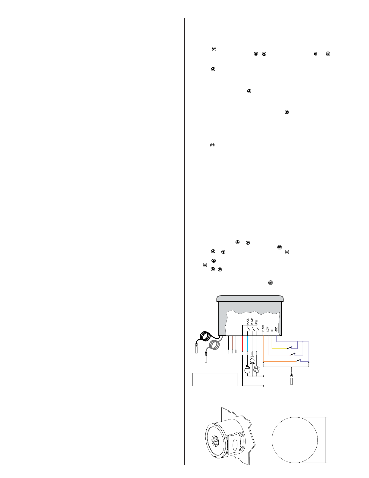
9 - WIRING DIAGRAM
High pressure switch
Low Pressure Switch
Flow switch
LOADS
SUPPLY
Digital
Inputs NF/
Sensor S3
S1
black
S2
gray
POWER SUPPLY
220 V - BLACK and BROWN wires
127 V - BLACK and GREY wires
Note: The sensor cable length can be increased by the user until 200 meters using the PP 2 x 24 AWG
cable.
BLACK
BROWN
GRAY
RED
BLUE
WHITE
GREEN
ORANGE
PINK
YELLOW
LILAC
S3
10 - FIXATION MODE
Dimension of the
clipping for setting of
the instrument in panel
Ø 60 mm
Page 3

11. IMPORTANT
According to the chapters of norm IEC 60364:
1: Install protector against overvoltage on the power supply
2: Sensor cables and signal cables of the computer may be joined, but not in the same electric
conduit through which the electric input and the activation of the loads run
3: Install transient suppressors (RC filters) parallel to the loads as to increase the product life of
the relays.
4: The withdrawal or substitution of the adhesive panel frontal as well as alterations in the
electronic circuit on the part of the user implies in the cancellation of guarantee.
Schematic for the connection of suppressors
to contactors
Supressor
A1
A2
A1 and A2 are the
contactor coils.
Schematic for the connection of suppressors
to direct activation loads
Load
Supressor
For direct activation the maximum
specified current should be taken
into consideration.
Suppressors on offer from Full Gauge Controls
ENVIRONMENTAL INFORMATION
Package:
The packages material are 100% recyclable. Just dispose it through specialized recyclers.
Products:
The electro components of Full Gauge controllers can be recycled or reused if it is
disassembled for specialized companies.
Disposal:
Do not burn or throw in domestic garbage the controllers which have reached the end-oflife.
Observe the respectively law in your region concerning the environmental responsible
manner of dispose its devices. In case of any
doubts, contact Full Gauge controls for assistance.
Copyright 2014
All rights reserved.
 Loading...