

Page 1
1. DESCRIPTION
MT-518Ri is a temperature controller with two outputs that can be configured as double stage of
refrigeration, double stage of heating or heating and refrigeration. Its second output also can be
configured for alarm intra, extra-range or, even , relative extra-range.
Product complies with CE (European Union) and UL Inc. (United States and Canada).
2. APPLICATION
• Winter/Summer automatic system in air conditioning
3. TECHNICAL SPECIFICATIONS
- Power supply: MT-518Ri 115 or 230 Vac ± 10% (50/60Hz)
MT-518RiL 12 or 24 Vac/dc
- Control temperature: -50 to 105ºC (decimal resolution between -10 and 100 ºC)
- Input: NTC sensor
- Load current: 8(3)A/250Vac 1/4HP each output
- Dimensions: 71 x 28 x 71mm
- Operation temperature: 0 to 50 ºC
- Operation humidity: 10 to 90% RH (without condensation)
UL-Underwriters Laboratories
MT-518Ri
DIGITAL TEMPERATURE CONTROLLER
WITH TWO STAGES
Ver. 12
MT518V12-01T-10873
CLASSIFICATION ACCORDING TO IEC60730-2-9 STANDARD:
- Temperature limit of the installation surface: 50°C
- Type of construction: Built-in electronic controller
- Automatic action: Type 1
- Control of pollution: Level 2
- Impulse voltage: 1,5kV
- Temperature for the test of sphere pressure: 75°C and 125°C
- Insulation: Class II
4. CONFIGURATIONS
4.1 - Control temperatures adjust (SETPOINTS)
- Press for 2 seconds until appears, then release it. will appear and the adjusted
temperature for 1st stage.
- Use the keys and to change the value and then press to record it.
- Now and the adjusted temperature for 2st stage will appear. ( only if F08 = 0 or F08 = 1).
- Use the keys and to change the value and then press again.
SET
SET
SET
Description
Min
Max
Unit
Fun
4.2 - Parameters table
Configuration parameters protected by access code.
Note: F02 function allows to correct eventual shuting lines in the reading, proceeding of the sensor
exchange or alteration of sensor length.
(4)
2nd stage operation
mode:
0 - refrigeration
1 - heating
2 - alarm (inside of
range)
3 - alarm (outside of
range)
4 - relative alarm
(outside of range)
(1)
First stage
operation mode:
0 - refrigeration
1 - heating
F01
F02
F03
F04
F05
F06
F07
F08
F09
F10
F11
F12
F13
F14
F15
Access code 123 (one hundred and twenty-three)
Display (offset)
(1)
1st stage operation mode
Minimum setpoint allowed to the end user (1st stage)
Maximum setpoint allowed to the end user (1st stage)
Control differential (hysteresis) of 1st stage
Minimum delay to turn on the 1st stage output
(2)
2nd stage operation mode
Minimum setpoint allowed to the end user (2nd stage)
Maximum setpoint allowed to the end user (2nd stage)
Control differential (hysteresis) of 2nd stage
Minimum delay to turn on the 2nd stage output
Alarm delay when the instrument is powered on
Alarm output time on
Alarm output time off
-
-5.0
0
-50
-50
0.1
0
0
-50
-50
0.1
0
0
0
0
-
5.0
1
105
105
20.0
999
4
105
105
20.0
999
999
999
999
-
°C
°C
°C
°C
sec.
°C
°C
°C
sec.
min.
sec.
sec.
4.3 - Parameters alteration
Access the function F01 pressing simultaneously the keys and for 2 seconds until appearing
, releasing after that. Soon it will appear , and then press (short touch).
- Use the keys and to enter with the access code (123), and then press to enter.
- Use the keys and to access the desired function.
- After selecting the function, press (short touch) to display the configured value for that function.
- Use the keys and to change the value and then press to record the new value and return
to the functions menu.
- To return to the normal operation, press until appear.
5. FUCTIONS WITH FACILITATED ACCESS
Registers of minimum and maximum temperatures
Press . The minimum registered temperature appears and after soon the maximum registered
temperature.
Nota: To reset the registers, keep the key pressed during the visualization of the minimum and
maximum temperatures until to be showed.
SET
SET
SET
SET
SET
If the instrument is configured as alarm, set the F09 and F10 act points normally and ignore ST2 and
F11. If the temperature goes out the specified range and ring the alarm, press and to inhibit the
sound.
6. SIGNALING
ST1 - 1st stage output on
ST2 - 2nd stage output on
- Detached sensor or temperature outside the specified range
With F08=4 the ST2 output is activated when the temperature reaches a value equal ST1 minus the
configurated value in F09 (ST1-F09), or when the temperature reaches a value equal ST1 plus the
configurated value in F10 (ST1+F10)
Ex. :
- Temperature in ST1 = 25 ºC
- Value in F08 = 4
- Value in F09 = 2
- Value in F10 = 5
The ST2 output will be kept on when the temperature is below 23 ºC (25-2) or above 30 ºC (25+5). If ST1
value is changed to 24 ºC the alarm values will be automatically modified to 22 and 29 ºC.
IF the functions F14 and F15 are set with zero, the ST2 output will be kepped on while the alarm
condition persist.
SET
ensoS
r
Power
supply
Load 1
COMMON
Loads
supply
ST1 (NO)
ST2 (NO)
1
2
3
4
5
6
7
8
9
10
11
12
115 V
(12 V)
230 V
(24 V)
0
72 mm
29 mm
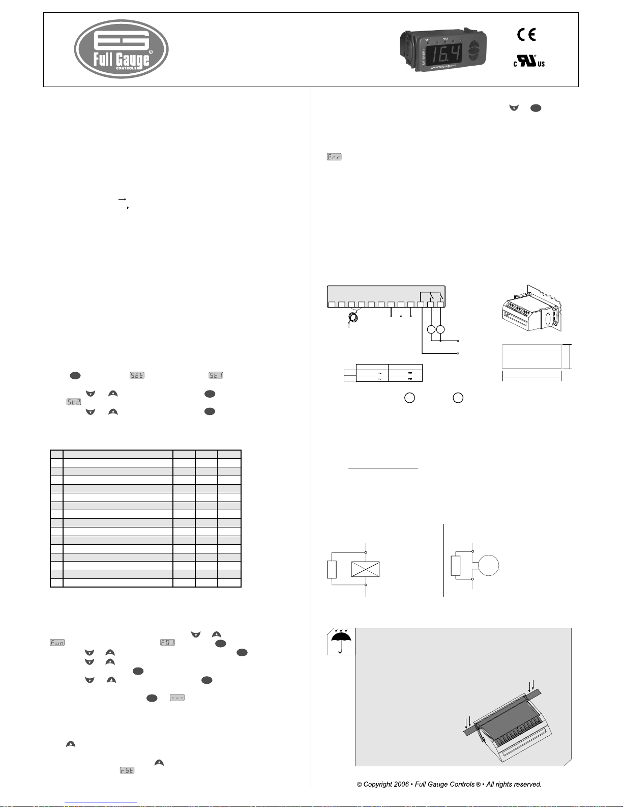
7. WIRING DIAGRAM
7 - 8
7 - 9
115V
230V
12V
24V
MT-518Ri MT-518RiL
Load 2
- Refrigerator
- Heating
- Contactor
- Solenoid
- Refrigerator
- Heating
- Contactor
- Solenoid
Load 1 Load 2
Above specified current use contactors.
Dimension of the clipping for
setting of the instrument
IMPORTANT
For more information contact our application eng. department through e-mail
support@ fullgauge.com or dial +55 51 3475.3308.
According to the chapters of norm IEC 60364:
1: Install protector against overvoltage on the power supply
2: Sensor cables and signal cables of the computer may be joined, but not in the same electric conduit
through which the electric input and the activation of the loads run
3: Install transient suppresors (RC filters) parallel to the loads as to increase the product life of the
relays.
Contact suppresor connection diagram
Suppresor
A1
A2
A1 e A2 are the
contactor coils.
Diagram for suppresor installation
for direct drive load inputs
Load
Suppresor
For direct activation the maximum
specified current should be taken
into consideration.
Note: The user can increase the length of the sensor cable to up to 200 meters, by using PP 2 X 24 A WG
cable. For immersion in water, use thermometric well.
PROTECTIVE VINYL:
This adhesive vinyl (included inside the packing) protects the instruments against
water drippings, as in commercial refrigerators, for example.
Do the application after finishing the electrical connections.
UL-Underwriters Laboratories
MT518V12-01T-10873
SET
Loads
72 mm
29 mm
- Refrigerator
- Heating
- Contactor
- Solenoid
Dimension of the clipping for
setting of the instrument
Load
For direct activation the maximum
specified current should be taken
into consideration.
Remove the protective paper
and apply the vinyl on the entire
superior part of the device,
folding the flaps as indicated by
the arrows.
 Loading...