

Page 1
MICROSOL II plus
DIFFERENTIAL TEMPERATURE CONTROLLER
FOR SOLAR HEATING WITH TWO
SOLAR BACKING
Ver. 02
UL-Underwriters Laboratories
MCSOL2V02-05T-10793
1.DESCRIPTION
Differential temperature controller for automation of solar heating systems,
MICROSOL II plus
becomes simple the management of the temperature of the water in the thermal reservoirs and
swimmingpools,use thesolarenergybetter..
Itactsinthecommand ofthewatercirculationpumpthrough the differentialoftemperaturebetweenthe
solarcollectors and the thermal reservoir orswimmingpool.It is a dedicated instrument thathasall its
parametersofconfiguration protectedbyaccesscode.
It makes use of two solar backings outputs, that can be electric, gas, diesel or also to program the
filteringoftheswimmingpool. solar backing1istiedwithan schedule thatallowstheconfigurationofup
to four daily events for each day of the week and solar backing 2 can optionally be configured for
functioninginset withtheschedule.
Ithasfunctions that prevent the water freezing and overheating inthetubingsanda clock with internal
batterytoguarantee itssynchronism,evenintheenergylack,permanyyears.Theinstrument hasserial
communicationforconnection withtheSITRAD viaInternet.
®
Productcomplieswith CE(EuropeanUnion)and ULInc.(United StatesandCanada).
2.APPLICATION
•Solarheating pumpedsystems
3.TECHNICAL SPECIFICATIONS
-Powersupply:
-Controltemperature:
115or 230Vac±10%(50/60Hz)
-50to105°
-58to221 ºF
-Resolution:
0.1°Cbetween-10 and100°Cand1°C intherestof therange
1°Fbetween-58 and221°F
-Dimensions:
-Operatingtemperature:
-Operatinghumidity:
-Sensors:
71x28 x71mm
0to50°C /32to122°F
10to90% RH(withoutcondensation)
S1-Sensor ofthecollectors
S2-Sensor oftheReservoir/Pool
S3-Sensorfor controlofsolarbackings
-Controloutputs:
PUMP-Waterpumporsolenoid -5(3)A/ 250Vac1/8HP
AUX1-solar backing1-5(3)A/250Vac1/8HP
AUX2-solar backing2-5(3)A/250Vac1/8HP
CLASSIFICATIONACCORDINGTOIEC60730-2-9STANDARD:
-Temperaturelimitof theinstallationsurface:
-Typeofconstruction:
-Automaticaction:
-Controlof pollution:
-Impulsevoltage:
Built-inelectroniccontroller
Type1
Level2
1,5kV
-Temperatureforthe testofspherepressure:
-Insulation:
ClassII
50°C
75°Cand125°C
4.CONFIGURATIONS
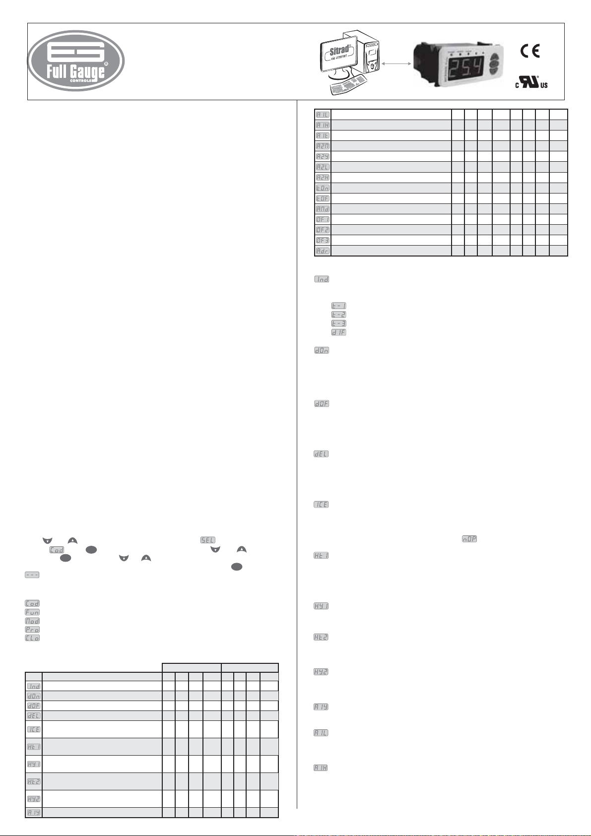
4.1- Toenter into the functionsmenu
Press and simultaneously for two seconds until it appears , then releasing it. When
appears press (tap) and enter thecode (123) through keys and .Toconfirm,
pressthekey .Throughthekeys and accessthe otherfunctionsandproceedin thesame
manner to adjust them. Toleavethe menu andreturn to normal operations, press (longhit) until
SET
SET
SET
appears.
4.2- Functions
Accesscodeentry
Advancedconfigurationfunctions
Eventsplanneroperating mode
Schedulinginthe eventsplanner
Adjustmentofthe clockandtheday oftheweek
4.2.1- Parameters table
Fun
Indication ofthepreferentialtemperature
Differentialforturningonthewatercirculation pump
Differentialforturningoffthewater circulation pump
Minimum timeforthepumpoff
Temperatureofthe antifreeze for sensor 1
to turnthewatercirculationpumpon
Overheat temperatureforsensor1
to turnthewatercirculationpumpoff
Overheated hysteresisforsensor1
for turningthewatercirculationpumpbackon
Overheat temperatureforsensor2
to turnthewatercirculationpumpoff
Overheated hysteresisforsensor2
for turningthewatercirculationpumpbackon
Hysteresis ofthesolarbacking1operation
Description
CELSIUS
Unit
Max
Min
-
1.0
1.0
0
3.0
0.0
0.1
0.0
0.1
0.1
Standard Standard
-
°C
20.0
°C
20.0
sec.
999
°C
10.0
°C
99.9
°C
20.0
°C
99.9
°C
20.0
°C
20.0
99.9
99.9
FAHRENHEIT
Unid
Max
Min
-
2
36
8.0
2
36
4.0
0
999
0
38
50
3.0
32
212
1
36
1.0
212
32
36
1
1.0
36
1
1.0
-
-
14
°F
7
°F
0
sec.
38
°F
212
°F
1
°F
212
°F
1
°F
1
°F
Minimum setpointofthesolarbacking1operation
Maximum setpointofthesolarbacking1operation
Manual activationtimeforsolarbacking1
Solar backing2operationmode
Hysteresis ofthesolarbacking2operation
Minimum setpointofthesolarbacking2operation
Maximum setpointofthesolarbacking2operation
Cyclical timertimeon
Cyclical timertimeoff
Method forlinkingthesolarbackingstothe events schedule
Indication offsetforthetemperatureofthe sensor 1
Indication offsetforthetemperatureofthe sensor 2
Indication offsetforthetemperatureofthe sensor 3
Address oftheinstrumentontheRS-485network
-50.0
-50.0
0.1
-50.0
-50.0
-5.0
-5.0
-5.0
-50.0
221
°C
105.0
°C
105.0
min.
999
0
5
0
°C
20.0
°C
105.0
°C
105.0
min.
999
1
min.
999
1
3
0
°C
5.0
°C
5.0
°C
5.0
247
1
-58
105.0
221
-58
0
999
0
0
1.0
-50.0
105.0
0.0
0.0
0.0
0
1
221
-58
221
-58
1
999
1
1
999
1
0
0
-9
-9
-9
1
247
1
-
-
-
-58
°F
221
°F
0
min.
0
-
5
1
°F
36
-58
°F
221
°F
1
min.
1
min.
0
-
3
0
°F
9
0
°F
9
0
°F
9
1
-
4.2.2 - Parameters description
Indicationofthepreferential temperature
Thisfunctionallowsthe preferentialtemperatureindicationtobe configured.Youmay choosebetween:
temperatureinthesensor 1
temperatureinthesensor 2
temperatureinthesensor 3
differentialtemperature(S1-S2)
Differentialforturningon thewatercirculationpump
Thisfunctionallowstheadjustmentofthedifferentialtemperature(S1-S2)to activate the water circulation
pump. As the solar collectors receive energy, the temperature in sensor S1 increases. When this
temperatureisatavalueestablishedasbeing above the temperature ofsensorS2,thepumpisturnedon
andcirculatesunderthe heatedwater,storingit inthereservoir,for example.
Differentialforturningoff thewatercirculationpump
Thisfunctionallows the adjustment of the differentialtemperature(S1-S2)toturn off the water circulation
pump. With the pump on, the hot water circulates below and cools upwards. After which time, the
temperaturedifferencebetweenS1and S2 tendstodecrease.Whenthisdifferencefalls to anestablished
level,thepumpis turnedoffandthewater circulationstops.
Minimumtimeforthe pumpoff
Thisfunctionallowsthe adjustmentoftheminimumtimeoff thatthepumpshouldhave beforebeingturned
on again. This option avoids the pump from being turned on and off in short periods of time, which thus
increasestheusefullifethereof.Thisfunctionalsodefinesthe delay in the pump's activation onturningon
thecontroller.
Temperatureof the antifreezeforsensor1 to turnthewatercirculationpump on
Thisfunctionallowsadjustmenttothetemperatureforformingice in the collectors. When thetemperature
in the collectors (sensor 1) are very low (Ex.: winter nights), the pump is turned on from time to time, to
prevent the water from freezing in the pipes and damaging them. The hysteresis is set at 2°C/4°F.To
deactivatethisfunctiondecrease thevalueuntilthemessage appearsinthedisplay.
Overheattemperatureforsensor 1toturnthewater circulationpumpoff
This function allows the adjustment of the overheating temperature of the collectors, to turn off the water
circulation pump. When the temperature in the collectors (sensor 1) is above an established value, the
pumpisturnedofftokeeptheoverheatedwaterfromcirculatingthroughthepipesanddamagingthem(if
PVCpipesareused).
Overheatinghysteresisofsensor 1toreconnectthewater circulationpump
Adjustment of the hysteresis of the overheated temperature of sensor 1 to allow the water pump to be
turnedonagain.
Overheattemperaturefor sensor2toturn thewatercirculationpump off
This function allows the adjustment of the overheating temperature of the pool to turn the water
circulationpumpoff, avoidingthermaldiscomfort.
Overheatedhysteresisfor sensor2forturning thewatercirculationpump backon
Adjustmentofthehysteresisoftheoverheated temperature of sensor 2 toallowthewaterpumptobe
turnedonagain.
Hysteresisofthe solarbacking1operation
Adjustmentofthe hysteresisfortheactivation temperaturesetpointforsolar backing1.
Minimumsetpointof thesolarbacking1operation
Lower limit, the purpose of which is to avoid the accidental regulation of temperatures far below the
setpointofsolar backing1.
Maximumsetpointof thesolarbacking1 operation
Upper limit, the purpose of which is to avoid the accidental regulation of temperatures far above the
setpointofsolar backing1.
Page 2
Manualactivationtime forsolarbacking1
Timethatsolar backing 1 is activewhenit is activated manually. Once this period oftime is over,solar
backing1returns tofunctionautomatically.
Operationmodefor solarbacking2
Thisfunctionenables configuringthemodeof operationofthesolar backing2output.Themodesare:
“0”-thermostatforrefrigeration
“1”-thermostatforheating
“2”-thermostatforrefrigeration hitchedtotheevent schedule
“3”-thermostatforheating hitchedtotheevent schedule
“4”-cyclictimerwith initialstateon
“5”-cyclictimerwith initialstateonhitched totheeventschedule
Hysteresisofthe solarbacking2operation
Adjustmentofthe hysteresisfortheactivation temperaturesetpointforsolar backing2.
Minimumsetpointof thesolarbacking2 operation
Lower limit, the purpose of which is to avoid the accidental regulation of temperatures far below the
setpointofsolar backing2.
Maximumsetpointof thesolarbacking2 operation
Upper limit, the purpose of which is to avoid the accidental regulation of temperatures far above the
setpointofsolar backing2.
Cyclicaltimertime on
Thisfunctionenables settingthetimeduring whichthecyclictimer willkeepitsoutput on.
Cyclicaltimertime off
Thisfunctionenables settingthetimeduring whichthecyclictimer willkeepitsoutput off.
Methodforlinking thesolarbackingsto theeventsschedule
Thisfunctionenablessettingtowhichofthe 4dailyeventseachsolarbackingoutputwillbe hitched.The
possiblemodesare:
“0”-Aux1hitchedtoevents1,2,3,4 “2”- Aux1hitchedtoevents1,2
Aux2hitched toevents1,2,3,4 Aux2hitched toevents3,4
“1”-Aux1hitchedtoevent 1 “3”- Aux1hitchedtoevents1,2,3
Aux2hitched toevents2,3,4 Aux2hitched toevent 4
Indicationoffsetfor thetemperatureofthe sensor1
Thisfunctionallows theindicationoffsetforthetemperatureofsensor1tobeadjusted(collectors).
Indicationoffsetforthe temperatureofthesensor 2
Thisfunctionallowsthe adjustmentoftheindication offsetforthetemperatureofsensor2(reservoirs/pool).
Sensor3temperaturedisplay offset3
Thisfunctionallowsthe indicationoffsetforthe temperatureofsensor3tobeadjusted(solarbackings).
Addressoftheinstrument onthenetworkRS-485
Addressoftheinstrument inthenetworkfor thecommunicationwiththe software.
Remarks:inasingle network,therecannotbe morethanoneinstrumentwith thesameaddress.
IMPORTANT:
function .Assuch, does not allow invalid adjustments to be madein order to
guaranteeitsperfectfunctioning.
(*)The value adjustedinfunction should beobligatorilygreaterthanwhatis adjusted in
MICROSOL II plus
SITRAD
®
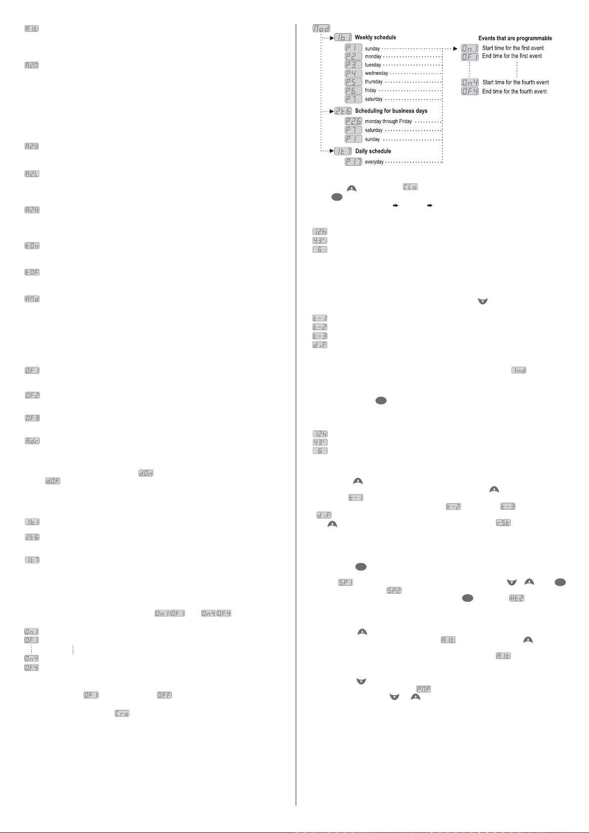
4.2.3 - Eventsscheduleoperating mode
Inthisoption,you canchoosehowthe eventsplannerwilloperate.
Weeklyprogramming
week.
Programming for business days
businessdays(MondaythroughFriday),andallowstheprogrammingofdifferent events for Saturday
andSunday .
Dailyprogramming
week.
-Inthismode,theinstrument can configure upto4eventsforeverydayof the
- In this mode, the instrument keeps the events the same for
-Inthismode,the instrument keeps theeventsthesameforallof the daysofthe
4.2.4- Programmingof the events schedule
Inthisoption,you canenterthevalues forthetimeperiodsfor eachevent.Theentryofthedatadepends
ontheoperatingmode configured.Youcan configure uptofoureventsfor each day.Foreachevent, the
startandend timeareconfiguredthrough theoptions upto , where:
Starttimefor thefirstevent
Endtimefor thefirstevent
Starttimefor the4ºevent
Endtimefor the4ºevent
Ifyoudonotneed to usethefourevents,youcan configure ittobedeactivated,andallyou havetodois
increase the off time ( for example) until the indication appears. It is also possible to
configureaneventtooverlap that itbeginsinonedayandit finishes intheother,andforthatyoushould
increasetheofftimeuntiltheoption appearsandadjustaneventforthenextdaytostartat00h
and00min.According to the operating mode configured, the following schedulingpossibilities may be
presented.
4.2.5 - Adjustmentof the currenttimeand day of the week
Pressthekey untilthe message appearsinthe visor.
SET
Hitkey .Thesettingswillappearinthefollowingorder:
HOURS MINUTES DAYOFTHEWEEK
Ex.:12h43min- Friday
Hours
Minutes
Dayofthe week
5.FUNCTIONS WHIT FACILITATEDACCESS
5.1- Visualize othertemperatures
To alternate between viewing the temperature of sensor 1, sensor 2, sensor 3 or the temperature
differencebetweensensor1 and2(differentialtemperature),press until thedesiredtemperatureis
showninthe display:
temperatureinthe sensor1
temperatureinthe sensor2
temperatureinthe sensor3
differentialtemperature(S1-S2)
Thetemperatureselectedwillbeshowninthedisplayfor fifteen seconds, and after that periodoftimehas
ended,thepreferentialindication willbeshownagain(as adjustedintheparameter ).
5.2- Visualize thecurrent time
Quickly pressing thekey , you can visualize the time set in the controller, the current time will be
SET
shown,followedby theminutesandthen thedayofthe week.
Ex.:12h43min- Friday
Hours
Minutes
Dayoftheweek
minimum and5.3 - Visualize maximum temperatures
Pressingthekey ,youcanvisualize the maximumandminimumtemperaturesforeach sensor,aswell
asthe minimum and maximumtemperaturedifferential. On pressing key (shorttouch), the message
will be shown showing the temperature of sensor 1 and soon after its minimum and maximum
temperatures,andthenthetemperaturesofsensor2( ),ofsensor3( )andthedifferential
().
Ifkey remainspressed,the values shall be restarted and the message shallbeshownon the
display.
5.4 - Set the operating tempera tures of the solar backings
(SETPOINTS)
Pressingthekey fortwosecondsmay adjusttheoperatingtemperatureforsolar backing 1andsolar
backing 2, as well as the overheating temperature for sensor 2 (reservoir/pool). A message will be
displayed ,adjusttheoperatingtemperature forsolarbacking1using keys e ,press
toconfirm.Thenthemessage willbedisplayed,adjusttheoperatingtemperatureforsolarbacking
2,pursuanttowhatisdescribedabove.After pressingthekey , the message willbedisplayed
toadjusttheoverheated temperatureforsensor2.
SET
SET
SET
5.5 - Manualactivation of solar backing 1
Pressing the key for ten seconds manually activates the output for solar backing 1. This will be
deactivated after the time adjusted in the function .lapses. By pressing key again for 10
seconds,themanual activationisdisabled,and solarbacking1resumes automaticoperation.
Todeactivatethemanualactivation, allyouhaveto doisconfigurefunction withthevalue“ 000”.
5.6- Manual activation of the watercirculationpump
By pressing key for 10 seconds, one can choose the mode of operation of the water circulation
pump.Afterpressing the key,themessage willbedisplayedandtheuser may thenchoosefromthe
optionslistedbelow,usingkeys and :
Page 3

Circulationpumpalways off
Circulationpumpalways on
Circulation pump operating in automatic mode without sensor 3 temperature validation. In this
modethecirculation pumpwillbeactivated onlybythediferential oftemperature(S1-S2)
Circulation pump operating in automatic mode with sensor 3 temperature validation. In this
mode the circulation pump will be activated by the diferential of temperature (S1-S2) and
whenthetemperature atsensor1is biggerthanatsensor 3.
Confirmtheselectionbypressingkey . The message willbedisplayed,showingtheendof
thefunction.
SET
5.7- Disabling thetemperature sensor 3
To disable the solar backing`s temperature sensor (sensor 3) enter the functions menu and access
function .Afterenteringthe functionpressthe buttonuntilthemessage appearsinthe
display,press the keytoconfirmandexit.
Whenthesensor 3isdisabledthe solarbackings1and 2willbecontrolledbysensor2(reservoir/pool).
If the circulation pump is adjusted for operation with sensor 3 validation and the sensor 3 was
deactivatedthecontroller willautomaticallydisablethe validation.
SET
6.SIGNALING
Sensor1(collectors) disconnectedoroutof range
Sensor2(reservoir /pool)disconnectedorout ofrange
Sensor3(solar backings)disconnectedorout ofrange
Temperatureforsensor1is freezing
Temperatureforsensor1is overheated
Temperatureforsensor2is overheated
Configurationparametersnot programmedoroutof range
Circulationpumpin offmanualmode
Circulationpumpin onmanualmode
7.UNIT SELECTION (°C /°F)
Todefine the unit that the system will use to operate, enter into the functions menu usingthe
access code “231” and confirm it by hitting key . The indication will appear,press or
tochoosebetween: or andconfirmwithkey .Afterselectingtheunitthe
SET
SET
messagewillappear,andtheinstrument will return to the function . Whenevertheunitisaltered,
theparametersshould bereconfigured,sincethey assume”standard”values.
IMPORTANT
Accordingtothe chaptersofnormIEC 60364:
1:
Install onthepower supply.
protectoragainstovervoltage
2:
Sensorcablesandsignalcables of the computer may be joined, but not in thesameelectricconduit
throughwhichthe electricinputandthe activationoftheloads run.
3:
Install transient suppresors (RC filters) parallel to the loads as to increase the product life of the
relays.
For more information,pleasecontactourTechnical Support by e-mail: or by
support@fullgauge.com
phone +5551 3475.3308.
Schematic for the connection of supresors
to contactors
A1
Suppresor
A1 andA2arethe
contactor coil terminals.
A2
Schematic for the connection of supresors to
direct activation loads
For direct activation themaximum
Load
specified current should betaken
Suppresor
into consideration.
PROTECTIVE VINYL:
This adhesive vinyl (included inside the packing) protects the instruments against
waterdrippings,as incommercialrefrigerators,for example.
Dotheapplication afterfinishingtheelectrical connections.
Remove the protective paper
andapplythevinyl on theentire
superior part of the device,
foldingtheflapsasindicatedby
thearrows.
8.WIRING DIAGRAM
9
230V
7
7
115V
Power
supply
9
8
8
10
10
PUMP
0
COMMON
Pump
Load 1
Above thecurrentspecified
use contactor
12
12
11
11
AUX1
AUX2
Load 2
Teardimensions
to position the instrument
Loads
supply
in the panel
72 mm
1
1
2
2
A
B
RS-485
Serial communication
Totheterminal of
the distributionbox
MICROSOLIIplus
9-8
9-7
3
3
Sensor 1
(collectors)
115V
230V
4
4
Sensor 2
(reservoir/pool)
5
5
6
6
Sensor 3
(solar backings)
Note: The sensor cable length can be increased by the user until 200 meters using PP 2 x 24 AWG
cable.
Integrating Controllers, RS-485 Serial Interface and Computer
®
External
mesh
Serial interface
RS-485
Full Gauge
terminal
grounded
RS-485SerialInterface
Device used to establish the
connectionFullGauge Controls’
instrumentswiththeSitrad
RS-485 Network
MOD 64
A
BB
B
A
AB
A
®
.
A
A
BB
B
A
A
BB
B
A
Instrument
Distribution Box
Usedtoconnectmorethan oneinstrument totheInterface.Thewire'sconnectionsmust
bemadein agreementwiththe followingrules:terminal oftheinstrument connectsto
theterminal of the distributionbox,thatmust be connectedwiththe terminal ofthe
Interface.Repeattheactionforterminals and , being thecableshield.
Theterminal ofdistributionbox mustbeconnected totherespective terminals of
eachinstrument.
A
B
MR
OUT4
L
A
OUT1
OUT2
3
T
OU
s
lu
p
R
0
0
-4
T
C
P
AA
RS-485 Network
A
A
BB
B
A
A
B
A
MP
U
P
s
lu
p
II
L
O
S
O
R
IC
M
X1
U
A
X
U
A
A
BB
2
A
B
A
A
B
A
B
29 mm
 Loading...