

Page 1
DIGITAL THERMOSTAT WITH
EVENT SCHEDULE
RT607EPLV03-02T-16701
5. INDICATIONS AND KEYS
1. DESCRIPTION
Digital temperature controller and indicator combined with a time scheduler which allows the user to
configure up to eight daily events, with programmable start and end time, which may be daily, weekly or
split into business days and weekends. It allows the user to activate the load manually even out of the
events. In addition to that, it offers parameters for recirculation and protection of water heaters. With the
sensor disabled it works as a time scheduler only. It includes serial communication for connection to
Sitrad.
2. SAFETY RECOMMENDATIONS
- Check the controller for correct fastening;
- Make sure that the power supply is off and that it is not turned on during the controller installation;
- Read the present manual before installing and using the controller;
- Use adequate Personal Protective Equipmenet (PPE);
- For application at sites subject to water spills, such as refrigerated counters, install the protecting vinyl
supplied with the controller;
- For protection under more critical conditions, we recommend the Ecase cover, which we make
available as an optional item (sold separately);
- The installation procedures should be performed by a qualified technician.
3. APPLICATIONS
• Air Conditioning
• Water heaters
• Displays with static coils
• Defrost control
• Ovens, injection machines
• All processes that require time scheduling
evolution
RT-607e plus
Ver
.03
(*) Acceptable variation in relation to the rated voltage.
(**) This device can measure and control temperatures of up to 200°C when used in conjunction with a model SB59
silicon sensor cable (sold separately)
Note: Sensor cable length can be increased to up to 200 meters by the user by using a PP 2 x 24 AWG cable.
4. TECHNICAL SPECIFICATIONS
Control temperature
-50 to 105ºC (-58 to 221°F)(**)
Electric supply
RT-607E plus: 115 or 230 Vac ±10%(*) (50/60 Hz)
RT-607EL plus: 12 or 24 Vac/dc +10%(*)
Operating temperature
0 to 50 ºC / 32 to 122°F
Operating humidity
10 to 90% RH (no condensation)
Dimensions (mm)
76 x 34 x 77 mm (WxHxD)
Maximum current/power per output
THERM - Thermostat control output:
16(12)A 250Vac 2HP
EVENT - Event schedule activation output:
10A / 240Vac ¼ HP
Dimensions for cutting – to fasten
the instrument
71 ± 0,5 x 29 ± 0,5 mm (see image V)
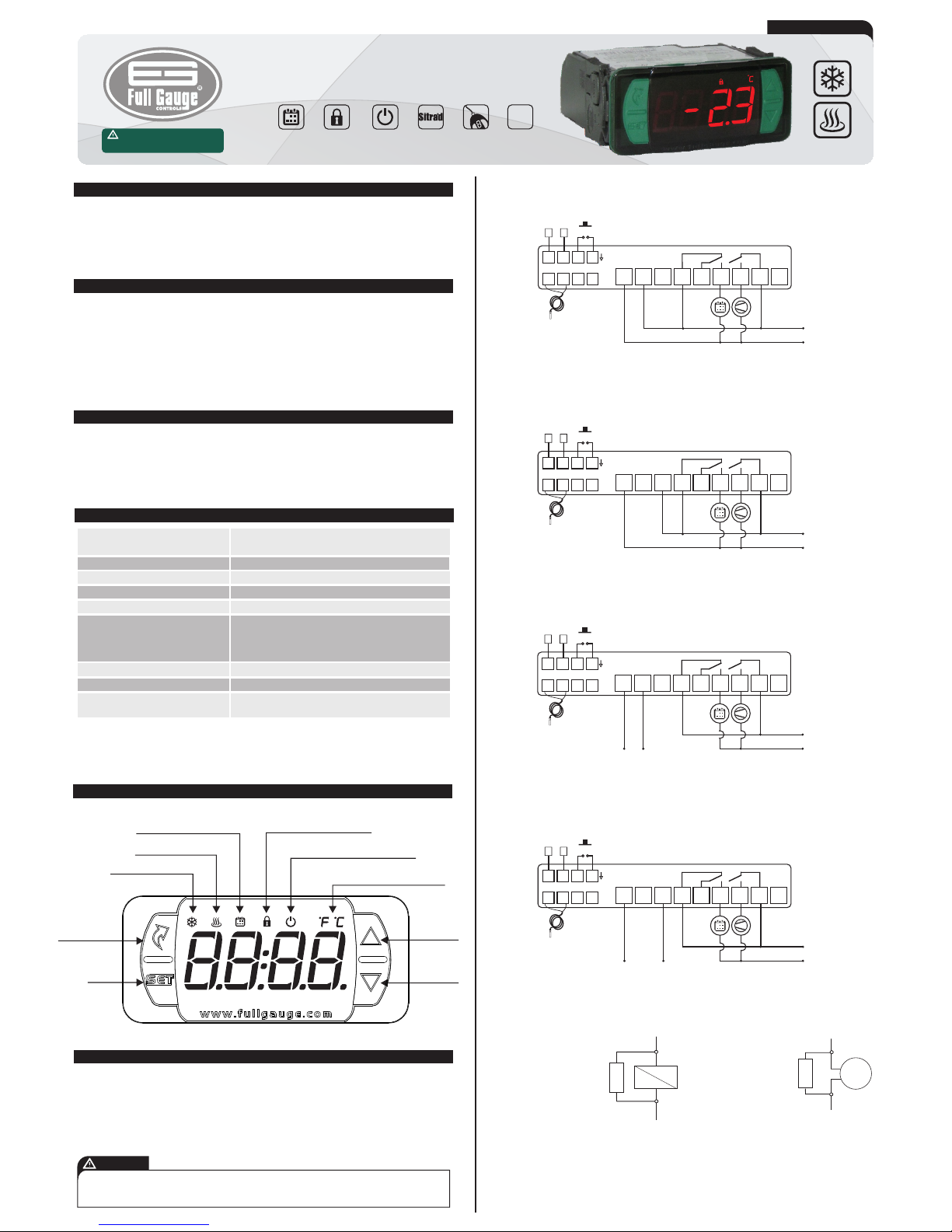
Set key
Quick access
menu key (Flatec)
Functions lock indication LED
Temperature unit indication LED
Increase key
Decrease key
Cooling indication LED
Heating indication LED
Event schedule indicator LED
RT-607e plus
Control functions off indication LED
6. WIRING DIAGRAM
6.1. Identifications (see Images I to IV)
- Image I: RT-607E plus , supplied at 115 Vac.
- Image II: RT-607E plus, supplied at 230 Vac.
- Image III: RT-607EL plus, supplied at 12 Vac/dc.
- Image IV: RT-607EL plus, supplied at 24Vac/dc.
6.2. Temperature sensor connection
- Connect the sensor wires to terminals ‘1 and 2’: the polarity is not relevant.
- Length of the sensor cables can be increased by user himself to up to 200 meters, using a PP 2x24
AWG cable.
Event
Schedule
Control
Functions
Shutdown
Functions
Lock
Serial
programming
Protection
level
IP 65
FRONT
Supervisory
system
Minimum interval between events
10 minutes
IMPORTANT
INSTRUMENTS IN THE EVOLUTION SERIES HAVE TWO DIFFERENT TERMINAL SIZES, BUT BOTH ARE
COMPATIBLE WITH THE SCREWDRIVER 2.0mm. USING THE APPROPRIATE TOOLS DURING INSTALLATION
ENSURES A LONGER LIFE AND THE PROPER OPERATION OF THE PRODUCTS.
RT-607e plus
RT-607e plus
Approximate consumption
0.7 VA
Have this manual in the palm of
your hand by FG Finder application.
1
5
678
2
3
4
9 10
11 121314
15 16
17
A
B
SITRAD
S1
D1
EVENT
THERM
Power supply
12Vac/dc
0
1
5
678
2
3
4
9 10
11 121314
15 16
17
A
B
SITRAD
S1
D1
EVENT
THERM
Power supply
24Vac/dc
0
Image I: RT-607E plus - 115Vac
Image III: RT-607EL plus - 12Vac/dc
Image II: RT-607E plus - 230 Vac
Image IV: RT-607EL plus - 24Vac/dc
1
5
678
2
3
4
9 10
11 121314
15 16
17
A
B
SITRAD
S1
D1
115 Vac
EVENT
THERM
1
5
678
2
3
4
9 10
11 121314
15 16
17
A
B
SITRAD
S1
D1
230 Vac
EVENT
THERM
Surge Protective Device (SPD) (sold separately)
W ir in g di ag ra m f or
in st alat ion o f SPD in
magnectic contactor
A1 and A2 are the terminals
of the contactor coil.
A1
A2
SPD
W ir i ng di ag r am fo r
instalation of SPD in line
with loads
For dir ect drive tak e in to
co nsid erat ion th e s pec ifie d
maximum current.
LOAD
SPD
Page 2
6.3. Controller power supply
Use the pins according to table below, considering the set version:
6.4. Recommendations of IEC60364 standard
a) Install overload protectors in the controller supply.
b) Install transient suppressors – suppressor filter RC – in the circuit to increase the service life of the
controller relay. See connection instructions of the filter on the previous page.
c) The sensor cables may be together, but not in the same conduit where the power supply of the
controller and/or of the loads passes through.
7. FASTENING PROCEDURE
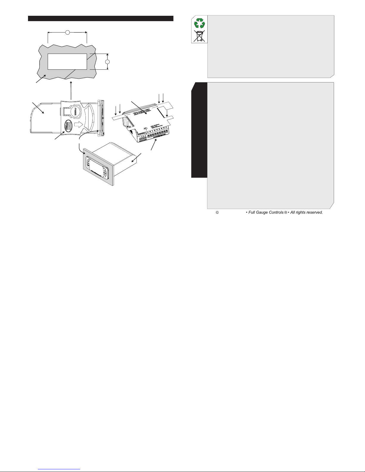
a) Cut out the panel plate (Image V - item 13) where the controller shall be fastened, with sizes
X = 71±0,5 mm and Y = 29±0,5 mm;
b) Remove side locks (Image VI - item 13): to do that, compress the central elliptical part (with the Full
Gauge Controls logo) and displace the locks backwards;
c) Introduce the controller in the notch made on the panel, inwards;
d) Place the locks again and then displace them until they compress into the panel, fastening the
controller to the housing (see arrow indication in Image VI - item 13);
e) Perform the electric installation as described in item 6;
f) Adjust the parameters as described in item 8.
ATTENTION: for installations requiring liquid tight sealing, the notch sizes for the controller
installation should be no more than 70.5x29mm. The side locks should be fastened so that they
press the sealing rubber avoiding infiltration between the notch and the controller.
Protector vinyl - Image VII (item 13)
It protects the controller when installed at a site subject to water spills, such as refrigerated counters.
This adhesive vinyl is supplied with the instrument in the package.
IMPORTANT: Make the application only after completing the electrical connections.
a) Retreat the side locks (Image VI - item 13);
b) Remove the protective film from the adhesive vinyl face;
c) Apply the vinyl over the entire upper part, bending the flaps, as indicated by the arrows - Image VII (item
13);
d) Reinstall the locks.
NOTE: The vinyl is transparent, allowing visualization of the wiring system of the instrument.
Pins RT-607E plus RT-607EL plus
9 and 10
9 and 11
115 Vac
230 Vac
12 Vac/dc
24 Vac/dc
8. OPERATIONS
8.1. Quick Access Menu Map
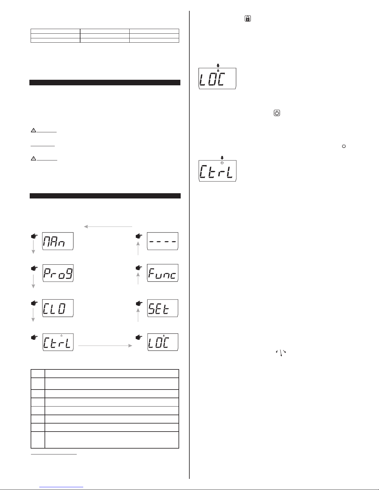
To access or browse the quick access menu use the ;key (quick touch) while the controller is
displaying the temperature/time. With each touch the next function in the list is displayed. To confirm use
the/ key (quick touch). See chapter 8.3 for more details. The map of functions is shown below:
8.3.2. Functions lock
The use of the functions lock brings greater security to the operation of the instrument. When it is active,
the setpoint and other parameters can be visible to the user, but are protected against undue changes
[,f15]= 2 or you can block changes of control functions and leave the adjustment of the setpoint
enabled [,f15]=1. Using the ;key (quick touch), access the function [LOC,] in the quick access
menu, confirm by pressing / (quick touch), then the message [no,,] will be displayed. After that
keep the > key pressed for the time configured for the functions lock[,f16]until [LOC,]is
displayed. The message [On,,]will be displayed indicating the function lock is activated upon
releasing the key.
RT-607e plus
To unlock, turn the controller off and then turn it on again with the > key pressed. Keep the key pressed
until [LOC,]is displayed. Keep the key pressed for 10 seconds and the message [OFF,] will be
displayed indicating the function lock is deactivated upon releasing the key.
8.3.3. Control functions shutdown
Turning the control functions off allows for the controller to operate just as an indicator of temperature,
keeping the control outputs and the alarms disconnected. Use of this feature is enabled or not by the
control functions shutdown function[,f17]. When enabled, the control and alarms functions are
turned off ([CTRL][OFF,]) or on ([Ctrl][ON,,]) through the quick access menu in the option
[Ctrl]. When the control functions are off the message [OFF,] will then be displayed alternately
with the temperature and the other messages.
Except when [,f17] is equal to 3 or 4, in which case the display is switched off, keeping only the .
icon on.
RT-607e plus
NOTE: It is also possible to switch the control functions on/off by pressing the ; key for five seconds.
NOTE: When switching the control functions back on, RT-607e plus will continue to respect the
functions “[,f06]- Minimum thermostat output off time”.
8.3.4. Minimum and Maximum Temperature Record
Holding the<key down (quick touch) or also via the quick access menu, will cause the message
[rEg,] to be displayed and the minimum and maximum temperatures to be recorded.
NOTE: If the<key is pressed while the events are being displayed the values will be reset and the
message [rsEt] will be displayed.
NOTE: If the temperature sensor is disabled the messages [____]and[++++]will be displayed.
8.3.5.View current date and time
Quickly pressing the/key makes possible to view the current date and time set in the controller.
However the display will show sequentially the current day ([,--d]), month ([,--m]), year
([,--y]), weekday([day-]), hour and minute ([00:00]) and if the preferred view set in [,f09]
is [Hour], the temperature is also displayed. It is also possible to view the date and time through the
quick access menu in the option [ClO,].
8.3.6. Manual triggering of event output
Pressing the key > for 10 seconds activates an event manually. This will be deactivated after the time
set in the [,f09] function has elapsed. Pressing the key > again for 10 seconds deativavates the
manual operation. When activating the manual trigger, the [Eon,] message and the [EOff]
message are displayed when you turn off the manual trigger. It is also possible to perform the activation
in the [man,] menu.
8.2. Quick access keys map
When controller is on temperature/time display mode, the following keys can be used as a shortcut for
the following functions:
Hold down for 2 seconds: setpoint adjustment (desired temperature).
/
<
Hold down for 10 seconds: manual activation of the event output.
Quick touch: enter the quick access menu.
;
/
Quick touch: the current day, month, year, day of the week, hour, and minute/
temperature will be shown in sequence on the display.
Quick touch: display of the maximum and minimum measurements recorded.
<
Hold down for 2 seconds: clear history when records are being displayed.
<
Hold down for 5 seconds: control functions shutdown.
;
Enters function selection.
<
<
8.3. Basic operations
8.3.1. Adjusting setpoint (desired temperature)
Hold the / key down for 2 seconds until the message [SET,]. is displayed. The adjusted control
temperature will be displayed when the key is released. Use the <or> key to change the value and
then press /to save. The desired temperature can also be changed in the quick access menu, (see
map on item 8.1).
;
FUNCTIONS LOCKDOWN
RT-607e plus
;
CONTROL FUNCTIONS
SHUTDOWN
RT-607e plus
;
ADJUSTING DESIRED
TEMPERATURE
(SETPOINT)
RT-607e plus
EXIT FUNCTION
;
RT-607e plus
FUNCTION SELECTION
;
RT-607e plus
RT-607e plus
SWITCH THE EVENT OUTPUT
ON/OFF (MANUAL MODE)
;
RT-607e plus
DATE AND TIME VIEW
;
;
SCHEDULE EVENT
PROGRAMMING
RT-607e plus
8.3.7. Date and time adjustment
Through the quick access menu, the [CLO,] option allows you to set controller date and time.
Use<or>to change the value and press/ when ready to save the configured value. If the date
entered is invalid, the message [ECLO]will be shown on the display.
Example 1 (correct access code entered):
[,00d]- day [,00M]- month [,00Y]- year [00:00]
time minute
flashing
IMPORTANT:
The controller has an auxiliary internal power supply to keep the clock running for at least 72 hours in
case of a power cut. If the controller remains off for a long period of time, the message [ECLO]may be
displayed to indicate that the clock is not programmed. In this case, the date and time must be adjusted
and the controller must be kept on for 10 hours to fully recharge the auxiliary power supply.
NOTE: To set the date and time through the menu outside the facilitated menu, it is necessary to enter
the access code 123.
a) Press the key ; (quick touch) simultaneously, < and > (quick touch), the [Code] option appears,
asking you to entered the access code.
b) Press / and enter the access code 123 using the < or > keys, confirming with the key /. The
[Code] option will again appear.
c) Navigate through the menu using the < or > keys until [Clo,] appears, and then press / key.
If the controller's clock is not programmed (message[ECLO]) it is possible to adjust the time even
when the functions are locked (message [LOC,] ). Under these conditions the clock adjustment is
enabled and the other functions remain locked. After the clock is adjusted the adjustment function is
locked again.
Page 3
8.3.8. Event schedule programming
This option allows entering the values of the time intervals for each event. Data input depends on the
configured operation mode. Up to eight events may be configured for each day. The start time and end
time of each event is set using options[,OnI]to [,On8][Off8], where:
[,On1] - Start time of the 1st event.
[OFF1] - End time of the 1st event.
.
.
.
[,On8] - Start time of the 8th event.
[OFF8] - End time of the 8th event.
NOTE: To program the event schedule outside the facilitated menu, it is necessary to enter the access
code 123. From the menu, press the key ; (quick touck) until you teach the [Prog] menu, skip steps a
and b and then press / (quick touch).
a)Press<and>(quick touch) simultaneously, the option[Code], will be displayed to request the
access code.
b)Press/and enter the access code 123 using the <or>key,confirming with/.The
option[Code]will appear again.
c)Browse the menu using the<or>key until the option[Prog]appears, and then press /. The
following programming options may be displayed depending on the operation mode:
[IbI,]- Weekly Programming
[mode]
[,,p1]- Sunday
[,,p2]- Monday
[,,p3]- Tuesday
[,,p4]- Wednesday
[,,p5]- Thursday
[,,p6]- Friday
[,,p7]- Saturday
[2t6,]- Weekdays Programming
[,p26]- Monday to Friday
[,,p7]- Saturday
[,,p1]- Sunday
[It7,]- Daily Programming
[,p17]- Every day
Events programmable by day
[,0n1]- Start time of the
1st event
[0ff1]- End time of the
1st event
[,0n8]- Start time of the
8th event
[0ff8]- End time of the
8th event
.
.
.
If it is not necessary to use all the eight events then they may be configured in the disabled mode by
increasing the switch off time ([Off1] for instance) until [Off,]is displayed. It is also possible to
configure an event to cross midnight by incrementing the switch off time until the option [Cro,] is
displayed and adjusting an event for the following day starting at 12:00 AM.
d)The time configured for the chosen event will be displayed. Use the<or>key to change the time
and press / again to return to the event programming menu.
e)To leave the event programming menu and return to the home screen, press/until the message
[----]is displayed.
Temperature control differential (hysteresis)
Sensor indication offset
Minimum setpoint allowed to the end user
Maximum setpoint allowed to the end user
Operation mode
Minimum thermostat output off time
Link the thermostat to the event schedule
Event schedule link mode
Time for manual activation of the event output
Preferred measurement view
Recirculation - Scan time
Interval between scans
Maximum time the thermostat output remains on
without reaching the setpoint
Thermostat output off time in state of alarm for not
reaching the setpoint
Digital input operation mode
Digital filter intensity applied to the sensor
Function lock mode
Time for functions lock
Control functions shutdown
Address of the instrument in the RS-485 network
[,f01]
[,f02]
[,f03]
[,f04]
[,f05]
[,f06]
[,f07]
[,f08]
[,f09]
[,f10]
[,f11]
[,f12]
[,f13]
[,f14]
[,f15]
[,f16]
[,f17]
[,f18]
[,f19]
[,f20]
Description
Fun
Min
Max
Unit
CELSIUS
FAHRENHEIT
Min
Max
Unit
StandardStandard
0.1
-5.1(off)
-50
-50
0(cool.)
0(no)
no
0
0(no)
temp.
0(no)
0(no)
0(no)
1
0(off)
0(no)
0
15
0(no)
1
8.5. Parameters table
20.0
5.0
200
200
1(heat.)
999
yes
7
999
all
999
999
999
999
2
9
2
60
4
247
°C
°C
°C
°C
-
sec.
-
-
min.
-
min.
min.
min.
min.
-
-
-
sec.
-
-
1.0
0.0
-50.0
105.0
1(heat.)
0(no)
yes
0
120
temp.
0(no)
0(no)
0(no)
1
0(off)
0(no)
0
15
0(no)
1
°F
°F
°F
°F
-
sec.
-
-
min.
-
min.
min.
min.
min.
-
-
-
sec.
-
-
1
-10(off)
-58
-58
0(cool.)
0(no)
no
0
0(no)
temp.
0(no)
0(no)
0(no)
1
0(off)
0(no)
0
15
0(no)
1
36
9
392
392
1(heat.)
999
yes
7
999
all
999
999
999
999
2
9
2
60
4
247
2
0
-58
221
1(heat.)
0(no)
yes
0
120
temp.
0(no)
0(no)
0(no)
1
0(off)
0(no)
0
15
0(no)
1
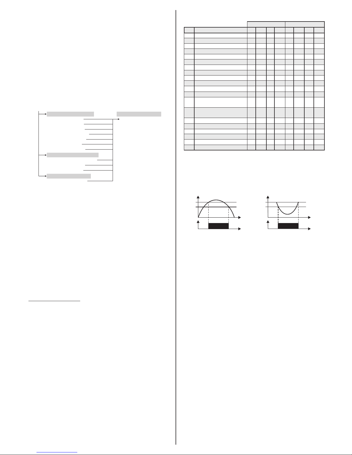
F01- Temperature control differential (Hysteresis):
It is the difference in temperature (hysteresis) between TURNING ON and OFF the cooling (or heating).
Example: One wants to control the temperature at 4.0 °C with a differential of 1.0 °C. Therefore, the
cooling is switched off at 4.0 °C and switched back on at 5.0 °C (4.0 + 1.0), in the heating mode the
output is switched off at 4° C and is switched on again at 3° (4.0 - 1.0), as per the charts below:
8.5.1. Description of parameters
Temperature [°C]
Cooling
Setpoint
Setpoint + Hysteresis
Time [S]
Relay Off
Relay On
4°C
5°C
Temperature [°C]
Heating
Setpoint
Setpoint - Hysteresis
Time [S]
3°C
4°C
Relay Off
Relay On
F02 - Sensor indication offset:
It allows compensating possible deviations in the temperature reading caused by the replacement of the
sensor or changes in the cable length. The temperature sensor can be switched off by adjusting this
function to the minimum value until the message[,OFF]is displayed. Under these conditions the
thermostat is disabled and the THERM output changes to the same state as the EVENT output.
F03 - Minimum setpoint allowed to the end user:
Avoids regulation of excessively low setpoint temperatures by mistake.
F04 - Maximum setpoint allowed to the end user:
Avoids regulation of excessively high setpoint temperatures by mistake.
F05 - Operation mode:
Allows selecting the controller operation mode.
[,,,0]- Refrigeration
[,,,1]- Heating
F06 - Minimum thermostat output off time:
It is the minimum time the thermostat output will remain off, i.e. the length of time between the last stop
and the next start up. It is used to relieve the discharge pressure and increase the service life of
compressor. This time is also used as an activation delay when the controller is switched on. This
function can be switched off by setting it at the minimum value 0 [No,,].
F07 - Link the thermostat to the event schedule:
This option allows linking the operation of the thermostat output to the event schedule. If the option 0
(no) is selected, the thermostat output will be controlled by the temperature only. In the case of option 1,
the thermostat output will be controlled by the temperature and will only be activated with a valid event in
the schedule.
F08- Event Schedule link mode:
This function allows the user to define whether the thermostat will work together with the event output or
not. Case the thermostat is linked to the event calendar (F07 = On), this function will inform which events
(times) the THERM and EVENT outputs will work. Otherwise, only EVENT events will be selected.
[,,,0] THERM linked to events 1,2,3,4,5,6,7 and 8.
EVENT linked to events 1,2,3,4,5,6,7 and 8.
[,,,1] THERM linked to event 1.
EVENT linked to events 2,3,4,5,6,7 and 8.
[,,,2] THERM linked to events 1,2.
EVENT linked to events 3,4,5,6,7e 8.
[,,,3] THERM linked to events 1,2,3.
EVENT linked to events 4,5,6,7e and 8.
[,,,4] THERM linked to events 1,2,3,4.
EVENT linked to events 5,6,7e 8.
[,,,5] THERM linked to events 1,2,3,4,5.
EVENT linked to events 6,7 and 8.
[,,,6] THERM linked to events 1,2,3,4,5,6.
EVENT linked to events 7 and 8.
[,,,7] THERM linked to events 1,2,3,4,5,6,7.
EVENT linked to event 8.
NOTE: By default, the event schedule leaves the factory with the same events for every day of the week,
and the schedules defined as fallows:
[,On1] - Opening time of 1st event: 04:00
[Off1] - End time of 1st event: 08:00
[,On2] - Start time of the 2nd event: 17:00
[Off2] - End time of the 2nd event: 21:00
Other events are disabled.
NOTE 2: When the event schedule operation mode is changed all events return to the default.
8.3.9. Unit Selection
To select the units that the system will use to operate, press<and>simultaneously as the
temperature is being displayed, enter the option[Code] using the access code [,231]and then
press/. Then select the desired unit[,=C,]or[,=F,]using the<>keys, and press/to
confirm.
NOTE: Whenever the units are changed, the functions’ configuration assumes the factory default, so
they need to be configured again.
8.4. Advanced operations
8.4.1. Adjustment of the parameters
Parameter adjustment can be done through the quick access menu (;) by accessing the option
[Func], or by pressing <and>simultaneously when the temperature/time is being displayed.
The following options will be displayed:
[Code]Entry to the access code
[Func]Change the advanced parameters
[Mode]Event schedule operation mode
[ProG]Event schedule programming
[ClO,]Adjustment or visualization of the date and time
8.4.2. Access code
To change the parameters or adjust the clock, select the[Code]option by pressing / (quick touch)
and entering the access code 123 (one hundred and twenty-three) using the<or>key, and confirm
with/.
Select the desired function using the<and>keys. Press/ (quick touch) after selecting the function
to view its value. Use<or>to change the value and press/when ready to save the configured
value and return to the functions menu. To leave the menu and return to the normal operating mode
(temperature indication), hold down/ (long touch) until[----]appears.
Note: If the function lock is active, the controller will show the message [LOC,]in the display upon
pressing <or> and will not allow the adjustment of the parameters.
8.4.3. Event schedule operation mode
In the main menu (after entering the code 123) select the option [Mode] and then the desired function
using the<or>keys. The factory default for the controller is [It7,]- Daily Programming.
To leave the menu and return to the normal operating mode (temperature indication), hold
down/(long touch) until [----]appears.
[IbI,]- Weekly Programming: In this mode the instrument can configure up to 8 events for each day
of the week.
[2t6,]- Weekdays Programming: In this mode, the instrument keeps the same events from
weekdays (Monday to Friday) and allows you to program different events for Saturday and Sunday.
[It7,]- Daily Programming: In this mode, the instrument keeps the same events for all days of the
week.
Page 4
11. GLOSSARY OF ACRONYMS
- °C: Temperature in Celsius degrees.
- °F: Temperature in Fahrenheit degrees.
- Heat.: Heating.
- LOC: Blocked.
- OFF: Turned off/disabled.
- ON: Turned on, enabled.
- Refr: Refrigeration.
- SET (as in "Setting") (setting or configuration).
- Vac: Electrical voltage (volts) of alternating current.
- Vdc: Electrical voltage (volts) of direct current.
9. SIGNALS
Error in sensor: Sensor disconnected or damaged.
[Err1]
[LOC,][On,,]
[LOC,][OFF,]
[OFF,]
[ClO,]
[EClO]
[ALrM]
[eCAL]
[pppp]
Functions lock.
Unlocking of functions.
Control functions off.
Contact Full Gauge Controls.
Reconfigure the values of the functions.
F09- Time for manual activation of the event output:
Time for which the event output remains on when manually activated. After this time has elapsed the
event output returns to the automatic operation. This function can be switched off by setting it at the
minimum value 0 [No,,].
F10 - Preferred measurement view:
It allows choosing which measurement will be displayed:
[Temp]- Temperature (if sensor is enabled).
[Hour]- Hour
[All,]- Switches between temperatures (if sensor is enabled) and time.
F11 - Recirculation - Scan time (if F05 = 1- heating):
Time during which the controller keeps the water circulation activated to equalize the water temperature
in the keg.
F12 - Interval between scans (if F05 = 1- heating):
It is the interval between the last and the next temperature scan.
NOTE: If the temperature to switch on the thermostat is reached the scan cycle is restarted.
F13 - Maximum time the thermostat output remains on without reaching the setpoint (if F05 = 1heating):
It is the maximum time the thermostat output will remain on without reaching the setpoint during the
heating process. When this time is exceeded the visual alarm [alrm] is activated and the thermostat
output remains off according to the time defined in F13. Functions F12 and F13 serves as protections for
the gas-fired heater so that in case of fault (flame out for instance), the water circulation is interrupted
and the heater is switched off to protect it.
This function can be switched off by setting it at the minimum value 0 [no,,].
F14 - Thermostat output off time in state of alarm for not reaching the setpoint (if F05 = 1heating):
It allows adjusting the time for which the controller will keep the thermostat output off while in state of
alarm for not reaching the setpoint. If the setpoint is reached during this time the alarm is switched off. If
the setpoint is not reached after this time has elapsed, new checks are performed during the time
defined in F12.
F15 - Digital input operating mode:
Allows the output associated with the event calendar to be associated outside of the schedule of events,
respecting the functions options and F07- Toggle thermostat to the event schedule and F09- Time of
manual activation of the event output.
[Off,] Off
[,,,1] Activate / deactivate manual override (NO button)
[,,,2] Activate / deactivate manual activation (NF button)
F16 - Digital filter intensity applied to the sensor:
This filter has the purpose of simulating an increase in thermal mass at the sensor thereby increasing its
response time (thermal inertia). The higher the value set in this function, the more time the sensor takes
to respond. This function can be switched off by setting it at the minimum value 0 [no,,].
F17 - Function lock mode:
It allows and configures the function lock.
[,,,0]Do not allow the function lock.
[,,,1]It allows a partial lock where the control functions will be locked but the adjustment of the
setpoint, date views, and maximum and minimum record views are allowed.
[,,,2]It allows the full lock, enabling only the date views and maximum and minimum record views.
F18 - Time for functions lock:
Allows lockdown of control functions (see item 8.3.2).
[,,15] - [,,60] - Defines the time in seconds for the controller to activate.
F19 - Control functions shutdown:
Allows the turning off the control functions (see item 8.3.3).
[,,,0]Disables the control functions shutdown.
[,,,1]Enables activation/deactivation of the control functions only if the functions are unlocked.
[,,,2]Enables activation/deactivation of the control functions even if the functions are locked.
[,,,3]It enables the activation/deactivation of the control functions only if the functions are unlocked,
switching off the display.
[,,,4]Enables activation/deactivation of the control functions even if the functions are locked,
switching off the display.
NOTE: In options 3 and 4 the display is switched off if no keys are pressed and switched on when any
key is pressed, remaining on for five seconds.
F20 - Address of the instrument in the RS-485 network:
Equipment's network address for communicating with Sitrad® software.
Note: One network must not have different equipment with the same address.
Adjustment or visualization of the date and time.
Invalid date and/or time (adjust the clock).
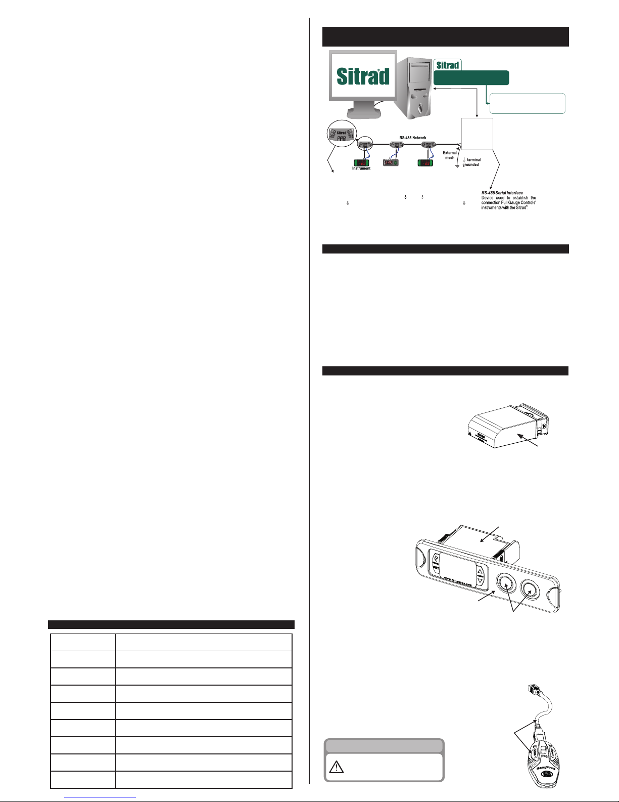
12. OPTIONAL ITEMS - Sold Separately
Ecase protective cover
It is recommended for the Evolution line, keeps water from entering the back part of the instrument. It
also protects the product when the installation site is washed.
ECASE PROTECTIVE COVER
Extended frame
It allows the installation of Evolution line controllers with sizes 76 x 34 x 77 mm in various situations,
since it does not require precision in the notch of the instrument fitting panel. The frame integrates two
switches of 10 Amperes that may be used to actuate interior light, air curtain, fan, and others.
CONTROLLER
EXTENDED
FRAME
SWITCHES
Alarm for failure to reach the setpoint.
10. INTEGRATING CONTROLLERS, RS-485 SERIAL INTERFACE
AND COMPUTER
AB
MT-530
super
AB
MT-530
super
A
A
B B
AB
A
B
A
A
B B
AB
A
A
B B
AB
A
A
B B
A B
*Connecting Block for Serial Communication
Used to connect more than one instrument to the Interface. The wire's connections must
be made in agreement with the following rules: terminal A of the instrument connects to
the terminal A of the connecting block, that must be connected with the terminal A of the
Interface. Repeat the action for terminals B and , being the cable shield.
the terminal of connecting block must be connected to the respective terminals of
each instrument.
*Sold Separately
CONV. 32
or
CONV. 256
Keep Sitrad updated in website:
http://www.sitrad.com
®
- version 2 or higherEasyProg
It is an accessory that has as its main function to store the parameters of the controllers. At any time, you
can load new parameters of a controller and download them on a production line (of the same
controller), for example. It has three types of connections to load or unload the parameters:
- Serial RS-485: It connects via RS-485 network to the controller (only
for controllers that have RS-485).
- USB: it can be connected to the computer via the USB port, using
Sitrad's Recipe Editor.
- Serial TTL: The controller can be connected directly to EasyProg
by the TTL Serial connection.
EASYPROG
IMPORTANT
TO PERFORM THE COMMUNICATION
WITH EASYPROG THIS EQUIPMENT MUST
NOT BE COMMUNICATING WITH SITRAD
SOFTWARE.
Watch Sitrad installation video in:
http://www.fullgauge.com/
videos/sitrad
Page 5
WARRANTY - FULL GAUGE CONTROLS
Products manufactured by Full Gauge Controls, as of May 2005, have a two (02) year
warranty, as of the date of the consigned sale, as stated on the invoice. They are guaranteed
against manufacturing defects that make them unsuitable or inadequate for their intended
use.
EXCEPTIONS TO WARRANTY
The Warranty does not cover expenses incurred for freight and/or insurance when sending
products with signs of defect or faulty functioning to an authorized provider of technical
support services. The following events are not covered either: natural wear and tear of parts;
external damage caused by falls or inadequate packaging of products.
LOSS OF WARRANTY
Products will automatically lose its warranty in the following cases:
- The instructions for assembly and use found in the technical description and installation
procedures in Standard IEC60364 are not obeyed;
- The product is submitted to conditions beyond the limits specified in its technical
description;
- The product is violated or repaired by any person not a member of the technical team of
Full Gauge Controls;
- Damage has been caused by a fall, blow and/or impact, infiltration of water, overload
and/or atmospheric discharge.
USE OF WARRANTY
To make use of the warranty, customers must send the properly packaged product to Full
Gauge Controls together with the invoice or receipt for the corresponding purchase. As much
information as possible in relation to the issue detected must be sent to facilitate analysis,
testing and execution of the service.
These procedures and any maintenance of the product may only be provided by Full
Gauge Controls Technical Support services in the company's headquarters at Rua Júlio de
Castilhos, 250 - CEP 92120-030 - Canoas - Rio Grande do Sul – Brasil
Rev. 03
ENVIRONMENTAL INFORMATION
Packaging:
The materials used in the packaging of Full Gauge products are 100% recyclable. Try to
perform disposal through specialized recyclers.
Product:
The components used in Full Gauge controllers can be recycled and reused if
disassembled by specialized companies.
Disposal:
Do not incinerate or dispose the controllers that have reached the end of their service as
household garbage. Observe the laws in your area regarding disposal of electronic
waste. If in doubt, please contact Full Gauge Controls.
Copyright 2016
13. ANNEXES - Reference Images
Image V
Image VI
Y
X
PANEL
PANEL
LOCKS
CONTROLLER
CONTROLLER
Image VII
VINYL
 Loading...