

Page 1

FOBQ 1000 G X
FOBQ 1000 G MBK
IT ISTRUZIONI PER L’INSTALLAZIONE E L’USO
EN INSTRUCTIONS FOR INSTALLATION AND USE
DE INSTALLATIONS- UND BEDIENUNGSANLEITUNG
ES
INSTRUCCIONES PARA LA INSTALACIÓN Y EL USO
BARBECUE DA INCASSO PER USO
DOMESTICO DA ESTERNO
BUILT-IN BARBECUE FOR HOME
OUTDOOR USE
EINBAU-GRILLKOFFER FÜR DEN
HAUSGEBRAUCH IM OUTDOOR-BEREICH
BARBECUE DE EMPOTRADO PARA USO
DOMÉSTICO EN EXTERIORES
Page 2

Page 3
IT
1
Complimenti
Complimenti e grazie per aver scelto il nostro barbecue
integrato. Siamo sicuri che sarà per voi un piacere usare
il nostro nuovo barbecue. Prima di usare il barbecue,
raccomandiamo di leggere tutto il manuale utente, che
fornisce la descrizione del barbecue e delle relative funzioni.
Per evitare quei rischi sempre presenti durante l’uso di un
apparecchio a gas, è importante installarlo correttamente e
leggere attentamente le istruzioni per la sicurezza, al fine di
evitare usi impropri e pericoli.
Raccomandiamo di conservare questo libretto di istruzioni
per consultazioni future e di consegnarlo ad eventuali
proprietari successivi.
Dopo aver tolto il barbecue dall’imballaggio, controllare
che non sia danneggiato. In caso di dubbio, non usare
l’apparecchio e contattare il più vicino centro di assistenza
clienti.
Suggerimento per l’ambiente Informazioni sullo
smaltimento per gli utilizzatori
• La maggior parte dei materiali di imballaggio è riciclabile.
Questi materiali vanno smaltiti tramite l’apposito centro
di riciclaggio locale o mettendoli in contenitori di raccolta
adeguati.
• Se si desidera gettare il prodotto, contattare gli uffici locali
competenti e informarsi sulla modalità di smaltimento
corretta.
INDICE PAG .
1 - Descrizione del prodotto 2
2 - Componenti 4
3 - Istruzioni importanti per la sicurezza 5
Utilizzazione 5
Responsabilita’ del costruttore 7
4 - Montaggio del barbecue 8
5 - Caratteristiche dei gas nei diversi paesi 10
Adattamento a diverso tipo di gas 11
Collegamento gas 12
Allacciamento metallico rigido/semirigido/
tubo in gomma 12
6 - Informazioni di sicurezza in merito alle
bombole del gas 14
Procedura di prova fughe 14
7 - Istruzioni di installazione e avvertenze 15
Scelta del punto di collocazione 16
Vano di installazione 16
Installazione stile isola 16
Installazione in un Top inserito in un’apposito
contesto 16
8 - Allacciamento della bombola di gpl 23
INDICE PAG .
9 - Applicazione del coperchio 24
Applicazione del coperchio basso 24
Applicazione del coperchio alto 25
10 - Istruzioni d’uso 26
Funzioni di controllo 27
Istruzioni di accensione 27
Accensione manuale 27
Preriscaldamento zone di cottura 27
Per spegnere il bruciatore 28
11 - Pulizia e cura 29
Pulizia e cura dell’apparecchio 29
Pulizia delle parti di cottura 29
Altre superfici in acciaio inossidabile 29
Pulizia delle griglie di cottura in ghisa 29
Pulizia delle griglie in acciaio inossidabile 29
Pulizia della vaschetta di raccolta olio 30
Bruciatori 30
12 - Manutenzione 31
Sistema di accensione 31
Aperture di ventilazione 31
13 - Risoluzione dei problemi 32
Page 4
IT
2
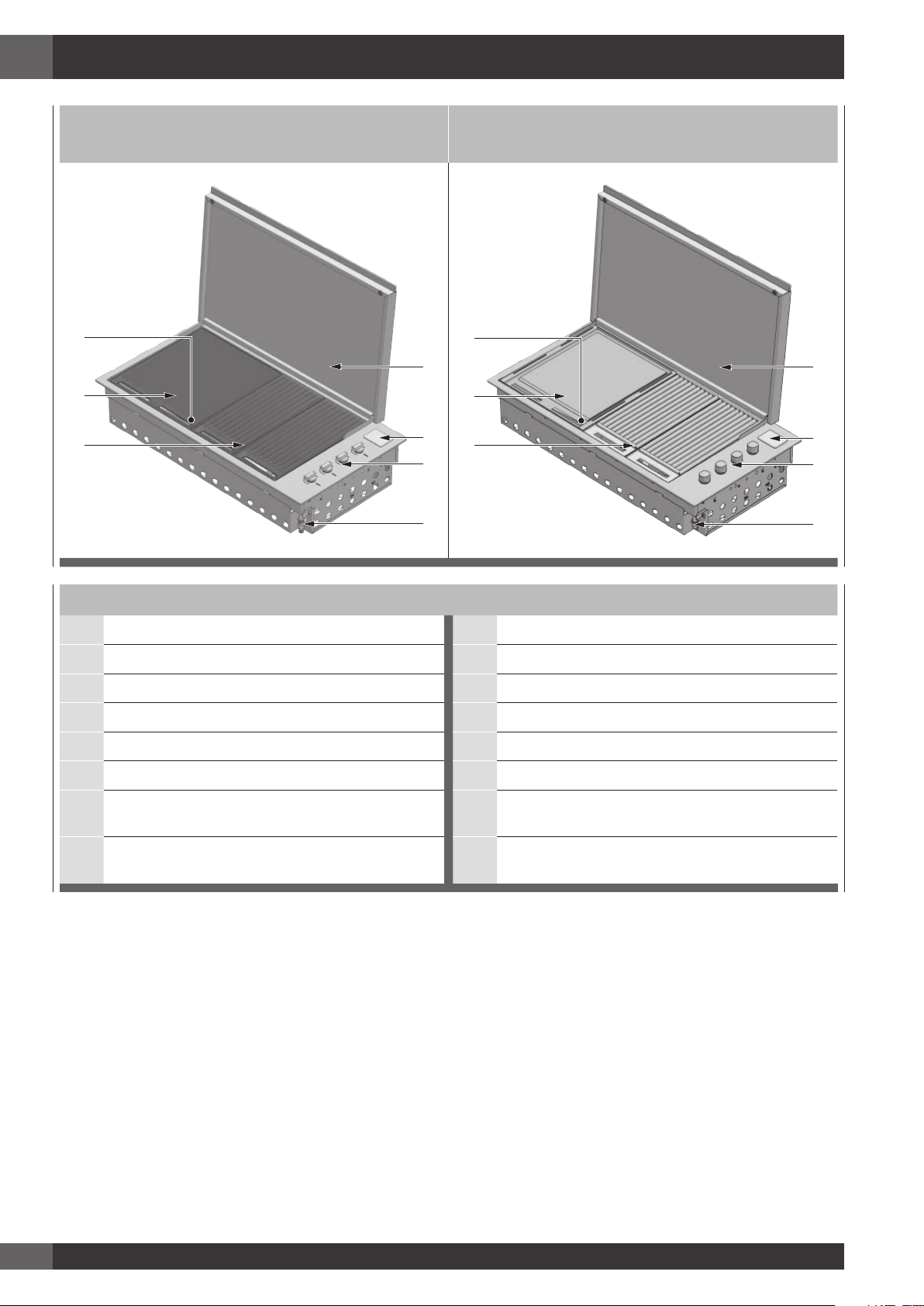
1 - Descrizione del prodotto
BARBECUE MOD. FOBQ 1000 G MBK
COPERCHIO BASSO MOD. FOBQ LL 1000 MBK
BARBECUE MOD. FOBQ 1000 G X
COPERCHIO BASSO MOD. FOBQ LL 1000 X
7
1
2
4
3
6
5
7
1
2
4
3
6
5
Barbecue integrato con coperchio sottile
1. Coperchio sottile 1. Coperchio sottile
2. Coperchio vano batteria 2. Coperchio vano batteria
3. Punto di allacciamento del gas 3. Punto di allacciamento del gas
4. Comandi dei bruciatori 4. Comandi dei bruciatori
5. Gruppo griglie in ghisa (2 set) 5. Gruppo griglia in acciaio inox (2 set)
6. Piastra di cottura 6. Piastra di cottura
7. Vaschetta di raccolta olio amovibile collocata
davanti al piano cottura (non illustrata)
7. Vaschetta di raccolta olio amovibile collocata
davanti al piano cottura (non illustrata)
8. Diffusori di fiamma (2 pz.) collocati sotto le griglie
(non illustrati)
8. Diffusori di fiamma (2 pz.) collocati sotto le griglie
(non illustrati)
Page 5
IT
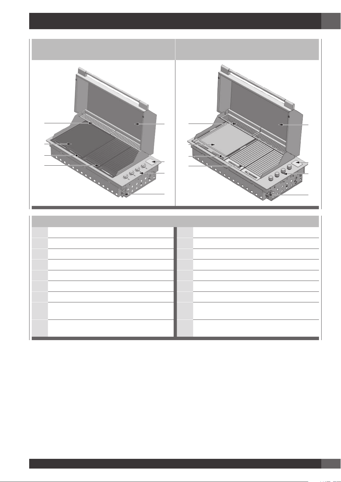
3
BARBECUE MOD. FOBQ 1000 G MBK
COPERCHIO ALTO MOD. FOBQ LL 1000 MBK
BARBECUE MOD. FOBQ 1000 G X
COPERCHIO ALTO MOD. FOBQ HL 1000 X
16
9
11
13
12
15
14
10
16
9
11
13
12
15
14
10
Barbecue integrato coperchio alto
9. Coperchio alto 9. Coperchio alto
10. Rastrelliere di riscaldamento 10. Rastrelliere di riscaldamento
11. Coperchio vano batteria 11. Coperchio vano batteria
12. Punto di allacciamento del gas 12. Punto di allacciamento del gas
13. Comandi dei bruciatori 13. Comandi dei bruciatori
14. Gruppo griglia in ghisa (2 set) 14. Gruppo griglia in acciaio inox (2 set)
15. Piastra di cottura 15. Piastra di cottura
16. Vaschetta di raccolta olio amovibile collocata
davanti al piano cottura (non illustrata)
16. Vaschetta di raccolta olio amovibile collocata
davanti al piano cottura (non illustrata)
17. Diffusori di fiamma (2 pz.) collocati sotto le griglie
(non illustrati)
17. Diffusori di fiamma (2 pz.) collocati sotto le griglie
(non illustrati)
Page 6

IT
4
QTÀ DESCRIZIONE QTÀ DESCRIZIONE
1
Scatola bruciatori e
profilo esterno
1
Piastra di cottura
massiccia in ghisa
4 Bruciatori 1
Piastra di cottura in
acciaio inox
2 Diffusori di fiamma 2 Gruppi griglie in ghisa
2
Diffusori di fiamma
(opzionale)
2
Gruppi griglie in acciaio
inox
1 Vaschetta per l’olio
CONFIGURAZIONE 1
QTÀ DESCRIZIONE
1 Coperchio Alto per cottura
CONFIGURAZIONE 2
QTÀ DESCRIZIONE
1 Coperchio Basso di copertura
2 - Componenti
Page 7
IT
5
Utilizzazione
Leggere attentamente il manuale utente e conservarlo in un luogo a portata di mano per esigenze
di consultazione futura.
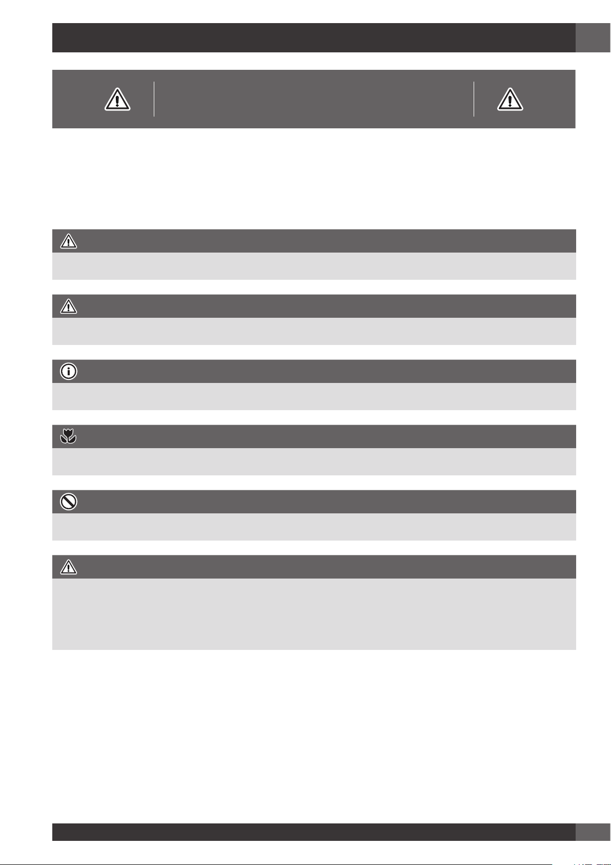
Viene mostrato qui di seguito il significato dei simboli usati in questo manuale:
ATTENZIONE
Questo simbolo segnala informazioni relative alla sicurezza personale dell’utente
AVVERTENZA
Questo simbolo segnala informazioni sul modo di evitare danni all’apparecchio
SUGGERIMENTI E INFORMAZIONI
Questo simbolo segnala suggerimenti e informazioni sull’uso dell’apparecchio
SUGGERIMENTO PER L’AMBIENTE
Questo simbolo segnala informazioni per un uso economico ed ecologico dell’apparecchio
DIVIETO
Questo simbolo segnala il divieto di compiere un’azione
ATTENZIONE
L’apparecchio DEVE essere installato e riparato solamente da personale qualificato e patentato.
L’installazione, la modifica delle regolazioni o la manutenzione effettuate in modo improprio
possono causare lesioni o danni a cose.
Del caso contattate il più vicino Centro di Assistenza Tecnica per avere ulteriori informazioni.
3 - Istruzioni importanti per la sicurezza
Per la propria sicurezza, l’utente è tenuto a leggere questo
manuale prima di mettere in funzione il barbecue.
Page 8

IT
6
DIVIETO
• Non piegarsi sul barbecue durante
l’accensione.
• Non lasciare il barbecue incustodito
quando è acceso.
• Non ritardare l’accensione una volta aperto
il gas.
• Non tenere o usare bombolette spray in
prossimità del barbecue.
• Non tenere liquidi infiammabili in prossimità
del barbecue.
• Non usare detergenti a base caustica o
abrasiva sul barbecue.
• Non mettere in funzione il barbecue con il
coperchio chiuso.
• Non cercare di smontare o sistemare i
rubinetti di comando.
• Non cercare di smontare o sistemare il
regolatore della bombola (non in dotazione)
ma eventualmente sostituirlo con uno nuovo.
• Non verificare la presenza di fughe con
una fiamma libera.
• Non modificare la struttura dell’apparecchio
e non modificare le dimensioni dell’orificio
degli iniettori.
DIVIETO
• Non ostruire le aperture di ventilazione del
barbecue.
• Non permettere ai bambini di mettere in
funzione il barbecue o di giocare vicino
ad esso Non utilizzare il barbecue se nel
raggio di circa 60 cm dalla parte superiore,
inferiore, posteriore o laterale del dispositivo
si trovano materiali infiammabili.
• Tenere eventuali cavi elettrici e tubi di
alimentazione carburante lontano dalle
superfici calde.
• Non tenere mai una bombola di gas di
ricambio vicino al barbecue.
• Questo dispositivo raggiunge temperature
elevate. Prestare particolare attenzione in
presenza di bambini o anziani.
• Non spostare l’apparecchio quando è
acceso.
• Indossare guanti di protezione durante
l’utilizzo del babecue.
• Tenere lontani i bambini di età inferiore agli
otto anni se non continuamente sorvegliati.
• Non tentare mai di spegnere una
fiamma/incendio con acqua: spegnere
l’apparecchio e coprire la fiamma con un
coperchio o con una coperta ignifuga.
NOTA PER L’INSTALLATORE: IL PRESENTE MANUALE DEVE RESTARE AL PROPRIETARIO PER
CONSULTAZIONE FUTURA
ATTENZIONE
SE SI SENTE ODORE DI GAS, non cercare di accendere il barbecue. Eseguire la procedura di
prova fughe come descritta nel manuale. Localizzare la fuga e riserrare il raccordo che perde se
quello della bombola sostituendo casomai anche la guarnizione di tenuta.
Se la fuga persiste, chiudere l’alimentazione di gas e chiamare l’assistenza tecnica.
Page 9

IT
7
DIVIETO
• Maneggiare con cura le bombole di gas
anche se sembrano vuote nel rispetto delle
norme sulla sicurezza in uso.
• Non utilizzare bombole di gas ammaccate
o arrugginite.
• Non scollegare la bombola di gas
dall’apparecchio quando è in funzione.
Eseguire qualsiasi intervento sulla bombola
di gas lontano dall’apparecchio.
• Accendere i bruciatori solamente a
coperchio sollevato.
• Se la manopola diventa difficile da ruotare,
fare controllare i rubinetti da un centro
assistenza autorizzato.
• Abbassare il coperchio accompagnandolo
con la mano facendo in modo che nulla si
interponga alla sua corretta chiusura.
• Durante la cottura a coperchio chiuso
tenete sotto controllo il termometro: e
se il valore supera i 350°C è necessario
sollevare il coperchio per evitare pericolosi
surriscaldamenti.
• Non lasciare oggetti sulle superfici di
cottura.
• Non usare in nessun caso l’apparecchio
per riscaldare l’ambiente.
• Chiudere sempre la valvola gas della
bombola a fine utilizzo.
Responsabilita’ del costruttore:
Il costruttore declina ogni responsabilità per
danni subiti da persone e cose causati da:
• uso dell’apparecchio diverso da quello
previsto;
• inosservanza delle prescrizioni del manuale
d’uso;
• manomissione anche di una singola parte
dell’apparecchio;
• utilizzo di ricambi non originali.
Page 10
IT
8
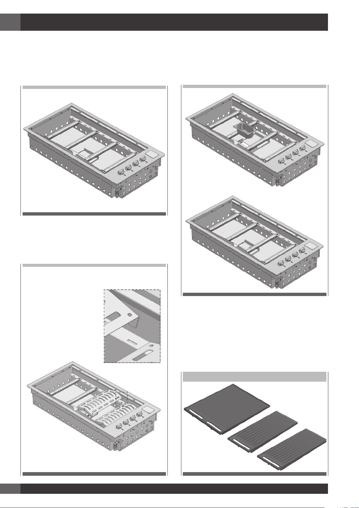
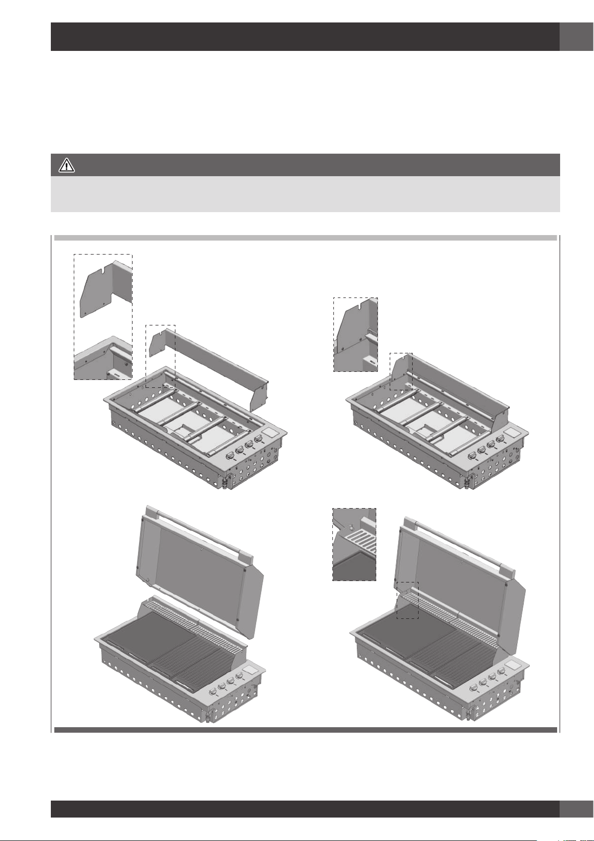
4 - Montaggio del barbecue
Utensili necessari per il montaggio:
- cacciavite con intaglio a croce
1. Togliere tutti i componenti dalla scatola.
RETRO
FRONTE
2. Collocare i diffusori di fiamma nelle posizioni desiderate
(sotto i punti (A) nei quali verranno messe le sezioni di
griglia) e attaccare il bordo posteriore del diffusore di
fiamma al retro del corpo del barbecue.
RETRO
FRONTE
3. Applicare le vaschette di raccolta olio alla parte anteriore
del barbecue.
RETRO
FRONTE
RETRO
FRONTE
4. Mettere la piastra di cottura e le sezioni di griglia nelle
posizioni desiderate accertandosi che i diffusori di
fiamma si trovino sotto le sezioni di griglia.
NOTA: assicurarsi che i gruppi griglie siano orientati
correttamente, in modo che la superficie della
griglia sia inclinata in avanti per permettere all’olio
di defluire nelle vaschette di raccolta
GRUPPI GRIGLIE IN GHISA
Page 11
IT
9
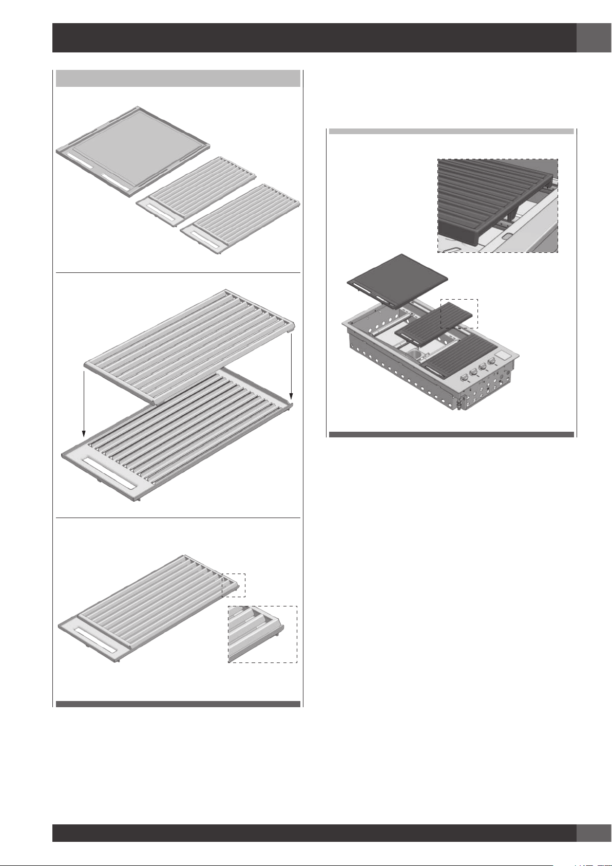
GRUPPI GRIGLIE IN ACCIAIO INOX
FRONTE
RETRO
5. Dopo l’installazione nel banco, collegare il coperchio
sottile o la cappa di cottura come descritto nel capitolo
“Applicazione del coperchio sottile o della cappa di
cottura” del presente manuale.
Page 12
IT
10
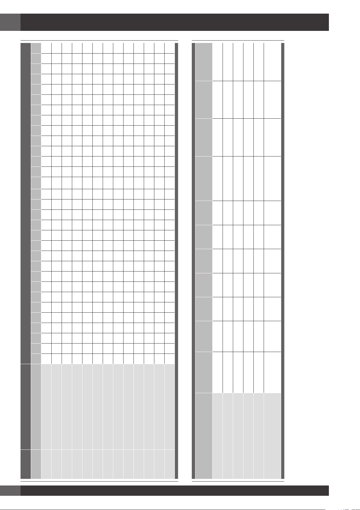
CATEGORIA GAS E PRESSIONI
PAESI DI DESTINAZIONE
AT BE CY HR DK EE FI FR DE GR IE IS IT LV LT LU MT NO NL PT PL GB CZ RO SK SI ES SE CH TR HU
I3+ G30 /G31 = 28-30/37 mbar • • • • • • • • • • • • • • •
I3B/P(30) G30 /G31 = 30 mbar • • • • • • • • • • • • • • • • • • •
I3B/P(37) G30 /G31 = 37 mbar •
I3B/P(50) G30 /G31 = 50 mbar • • • • •
2H G20 = 20 mbar • • • • • • • • • • • • • • • • • • • • • •
2E G20 = 20 mbar • • • • •
2E+ G20 = 20 mbar • •
2L G25 = 25 mbar •
2LL G25 /20 mbar • •
2H(25) G20 /25 mbar •
2S G25.3 /25 mbar • •
2Lw G27 /20 mbar •
2Ls G2.350/13 mbar •
G20-20
cat. 2H, 2E, 2E+
G20-25
cat. 2H(25)
G25-20
at. 2LL
G25-25
cat.2L
G25.3
cat.2S
G27
cat.2Lw
G2.350
cat.2Ls
G30 /G31
cat. I3+
G30 /G31
cat. I3B/P (30)
G30 /G31
cat. I3B/P (37)
G30 /G31
cat. I3B/P (50)
Portata termica nominale (kW) 15,2 15,2 15,2 15,2 15,2 15,2 15,2 15,2 15,2 15,2 15,2
Diametro iniettore (1/100mm) 135 130 155 145 145 155 194 94 94 89 83
Numero iniettori 4 4 4 4 4 4 4 4 4 4 4
Pressione (mbar) 20 25 20 25 25 20 13 28..30/30..37 30 37 50
Consumo massimo (l/h) 1448 1448 1684 1684 1683 1766 2011 1106 1106 1106 1106
Regolazione aria primaria (mm)
(X) vedi fig. pag. 12
1 1 1 1 1 1 1 Tutto aperto Tutto aperto Tutto aperto Tutto aperto
5 - Caratteristiche dei gas nei diversi paesi
Page 13
IT
11
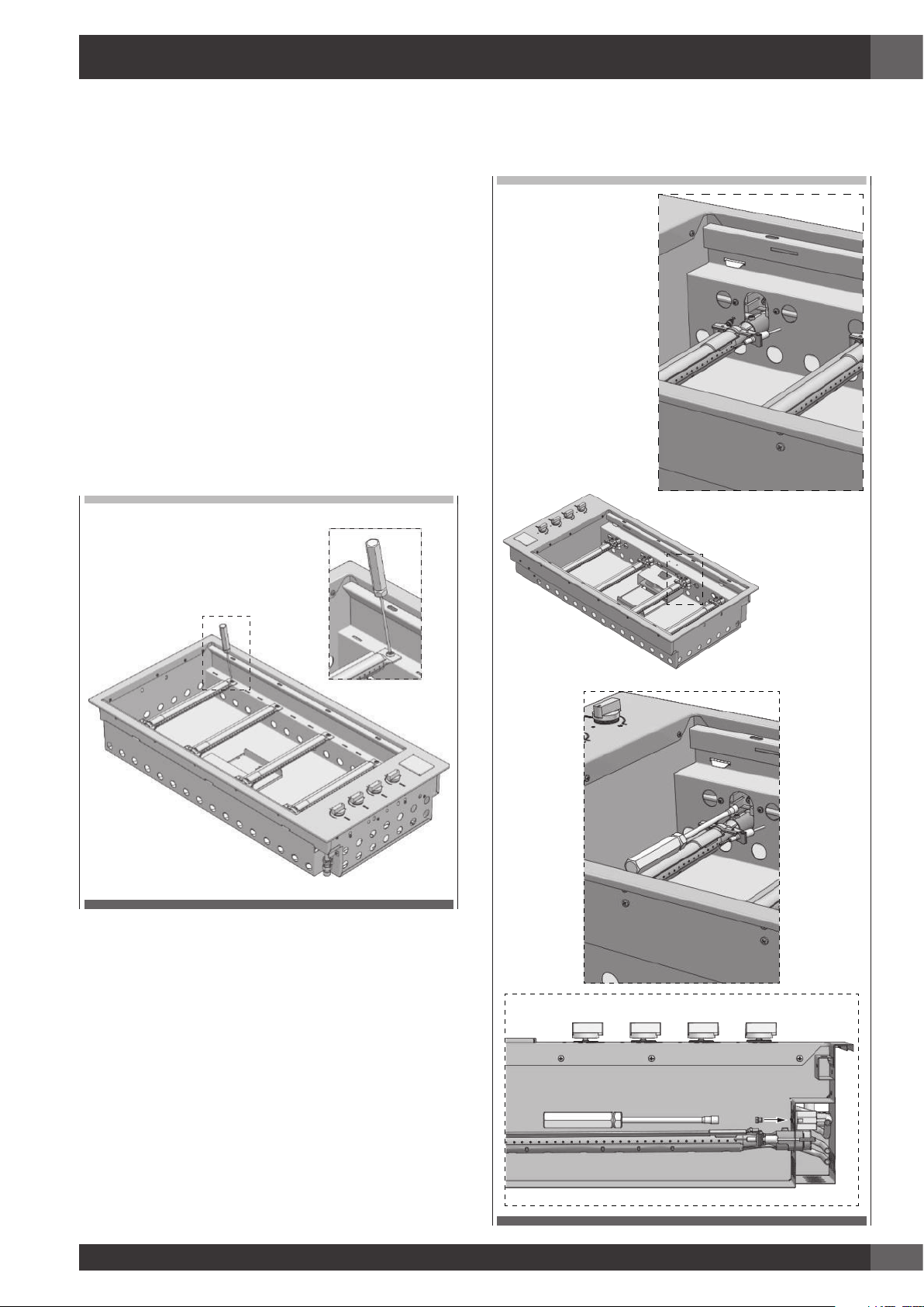
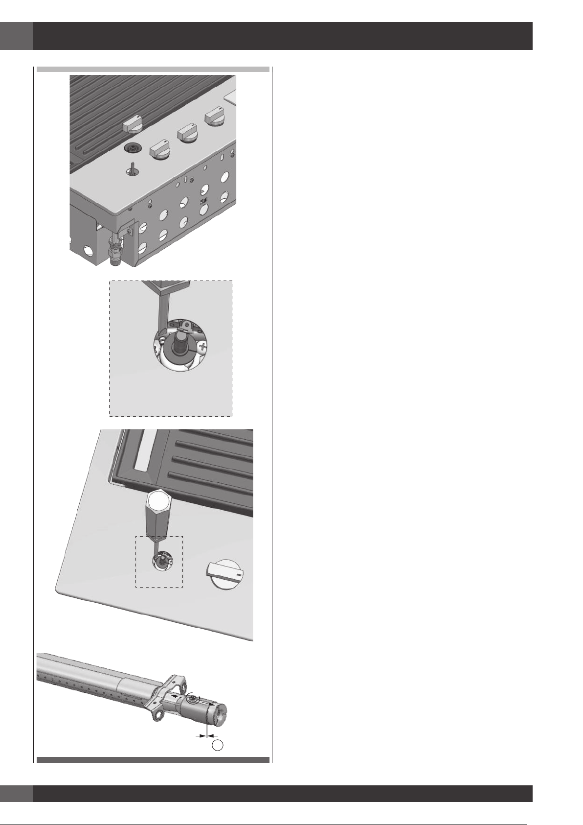
Adattamento a diverso tipo di gas
Se l’apparecchiatura risulta predisposta per un diverso
tipo di gas da quello di alimentazione disponibile, si deve
procedere alla sostituzione degli iniettori con i corrispondenti
al tipo di gas da utilizzare (vedi tabelle pagine precedenti).
La sostituzione va fatta usando un’apposita chiavetta da
7mm dopo aver abbassato i bruciatori come da immagini
che seguono. Una volta sostituito l’iniettore provvedere
a regolare l’Aria dello stesso portandolo a 1mm se per
metano e al massimo se a GPL.
Per la regolazione del minimo, una volta acceso il bruciatore,
tolto la manopola e la guarnizione sotto, ruotare l’apposita
vite del rubinetto (B - vedi pag. 12) che per il GPL va
totalmente chiusa mentre per il metano deve essere svitata
per circa 3/4 di giro ricordando che una fiamma più bassa
di 3mm può anche non venire “sentita” dalla termocoppia
del rubinetto. Una volta regolati i minimi, rimontare le
guarnizioni e le manopole relative.
1 - Svitare la vite di fissaggio bruciatore.
RETRO
FRONTE
2 - Abbassare il bruciatore e sostituire l’iniettore.
FRONTE
RETRO
Page 14
IT
12
X
NOTE
• L’apparecchio DEVE essere installato e riparato solamente
da personale qualificato e autorizzato.
• Il prodotto è destinato esclusivamente all’uso esterno.
• Il prodotto deve essere installato seguendo le istruzioni, che
richiedono delle aperture di ventilazione per permettere
al barbecue di funzionare correttamente. La mancanza di
un’adeguata ventilazione che fornisca l’alimentazione di
aria all’apparecchio può portare ad una scarsa efficienza
dei bruciatori o all’eccessivo sviluppo di calore all’interno
del vano di installazione.
• Le aperture di ventilazione dell’unità non devono essere
coperte durante l’installazione.
Collegamento gas
Collegare l’apparecchiatura alla bombola o all’impianto
secondo le prescrizioni delle norme in vigore accertandosi
preventivamente che l’apparecchiatura sia predisposta al
tipo di gas disponibile. In caso contrario vedi: “Adattamento
a diverso tipo di gas”. Verificare inoltre che la pressione
di alimentazione rientri nei valori riportati nella tabella:
“Caratteristiche del gas”.
Allacciamento metallico rigido/semirigido/tubo
in gomma
Eseguire l’allacciamento con raccordi e tubi metallici (anche
flessibili) in modo da non provocare sollecitazioni agli organi
interni all’apparecchio.
Il collegamento con tubo in gomma conforme alla norma vigente
può essere realizzato solamente se il tubo è ispezionabile in
tutta la sua lunghezza agevolmente sostituibile in prossimità
della scadenza indicata sul tubo stesso.
N.B. - Ad installazione ultimata controllare, con una soluzione
saponosa, la perfetta tenuta di tutto il sistema di collegamento.
NON UTILIZZARE FIAMME LIBERE PER IL CONTROLLO DI
TENUTA GAS
Page 15
IT
13
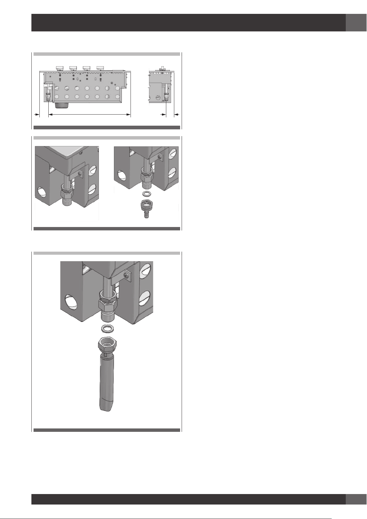
Dettaglio di allacciamento del gas
52 47488
Con nota: collegamento gas naturale GN.
Page 16

IT
14
6 - Informazioni di sicurezza in merito alle bombole del gas
• L’apparecchio, una volta fatta la conversione
per l’uso di GPL, è progettato per utilizzare
diversi tipi di bombola di gas a seconda
dell’installazione fatta. Vedi capitoli
relativi all’Installazione, Preparazione e
Allacciamento della bombola.
• La bombola del gas deve essere fabbricata
e marcata in accordo alle specifiche per le
bombole di GPL in uso nel paese.
• La valvola di isolamento deve essere chiusa
quando l’apparecchio non viene usato.
• Le bombole di gas devono essere tenute in
un alloggiamento appropriato fuori della
portata dei bambini.
• Quando si scollega la bombola del gas,
assicurarsi che i rubinetti di comando siano
in posizione di chiuso (O).
• Prima di scollegarla, togliere la bombola
dall’alloggiamento in cui eventualmente si
trova.
• Quando si ricollega il tubo alla bombola,
assicurarsi che tutti i collegamenti siano a
tenuta prima di riposizionarla nell’apposito
compartimento.
• Eseguire un controllo delle fughe come
descritto di seguito dopo ogni collegamento
di una nuova bombola.
Procedura di prova fughe
• Accertarsi che tutti i rubinetti del gas siano in
posizione di chiuso (O).
• In un piccolo contenitore, mescolare una
soluzione di acqua e detergente o sapone.
• Dopo il collegamento del tubo, aprire la
valvola sulla bombola del gas o eventualmente
il rubinetto di rete.
• Usando un pennello, applicare la soluzione
sui punti di collegamento del gas e controllare
se c’è formazione di bolle.
• La presenza di bolle indica una fuga.
• Chiudere la valvola e riserrare il raccordo
magari inserendo una nuova guarnizione.
Ripetere la prova fughe.
• Se la fuga persiste, chiudere il gas e contattare
un manutentore autorizzato e patentato di
impianti a gas per rimediare alla fuga.
Page 17
IT
15
7 - Istruzioni di installazione e avvertenze
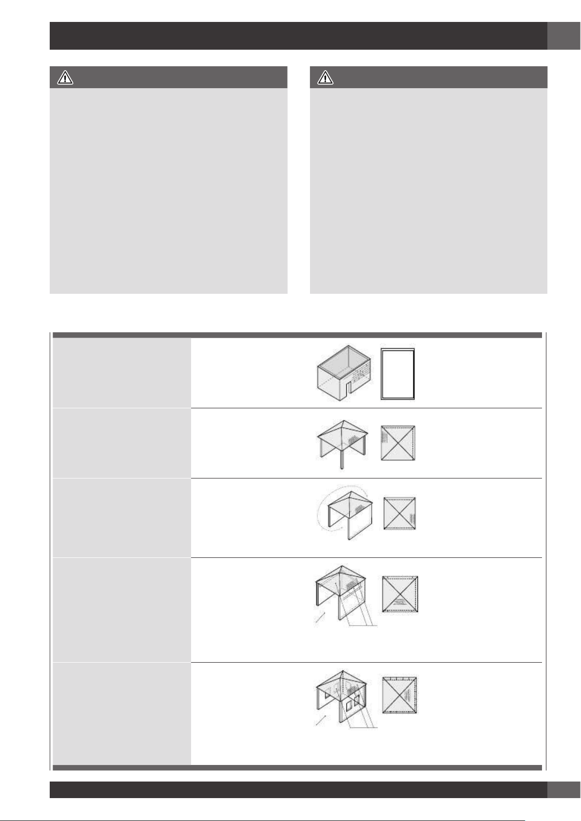
ATTENZIONE
• L’apparecchio deve essere usato soltanto sopra la
superficie del suolo, in condizioni di aria aperta con
ventilazione naturale e senza aree stagnanti, dove
le fughe di gas e i prodotti di combustione vengono
rapidamente dispersi dal vento o dalla convezione
naturale. Questo barbecue è stato progettato solo per
uso esterno. Fare riferimento ai disegni sottostanti.
• Non installare mai il barbecue all’interno di edifici,
garage, baracche o passaggi coperti oppure
all’interno di imbarcazioni, camper o caravan. Ciò
serve a prevenire il possibile sviluppo di incendi o di
monossido di carbonio con effetti tossici o di asfissia.
• Il vano in cui l’apparecchio viene installato deve essere
conforme ad uno dei seguenti requisiti:
ATTENZIONE
• Un vano con pareti su tutti i lati, ma con almeno
un’apertura permanente a livello del suolo e senza
copertura superiore.
• All’interno di un vano parziale che comprende una
chiusura superiore e non più di 2 pareti.
• All’interno di un vano parziale che comprende una
copertura superiore e più di 2 pareti; in questo caso si
applica il seguente principio:
• Almeno il 25% della superficie totale delle pareti è
completamente aperto e almeno il 30% della superficie
rimanente delle pareti è aperto e libero
• In caso di balconi, almeno il 20% della superficie
totale delle pareti laterali, posteriori e anteriori deve
essere e restare aperto e libero.
Superficie esterna esempio 1
Superficie esterna esempio 2
Superficie esterna esempio 3
entrambe le estremità aperte
Superficie esterna esempio 4
lato aperto per almeno il 25% della superficie totale delle pareti in totale il 30% o più
della superficie restante delle pareti è aperto e libero
Superficie esterna esempio 5
lato aperto per almeno il 25% della superficie totale delle paretiin totale il 30% o più
della superficie restante delle pareti è aperto e libero
Page 18
IT
16
Scelta del punto di collocazione
• L’apparecchio non deve essere installato su materiale
combustibile. La distanza minima da materiali
combustibili è di 600 mm.
• L’altezza libera sopra il piano cottura rispetto a materiali
combustibili deve essere di almeno 600 mm.
• L’apparecchio deve essere installato in conformità alle
norme e in accordo con le deviazioni locali.
• Durante l’uso di GPL all’interno di un vano deve essere
garantita la ventilazione. Il gas è altamente esplosivo e
può causare gravi lesioni e danni a cose se lo si lascia
accumulare e poi si infiamma.
• Il barbecue è destinato ad essere montato in un TOP con
profondità minima minima di 600 mm.
• Evitare le posizioni esposte al vento poiché potrebbero
risentirne la cottura e l’efficienza dei bruciatori. Se non
si può evitare una simile posizione, possono essere
necessari degli schermi.
Vano di installazione
• Il barbecue richiede una barriera non combustibile sotto
di esso per impedire che si raggiunga una temperatura
eccessiva in ottemperanza della Norma UNI EN 498
in vigore. Il pannello che funge da barriera deve essere
posizionato 30/35 mm al di sotto della base dell’unità.
• Il vano di installazione deve essere realizzato con
materiali non combustibili. Tra i materiali adatti per
la costruzione vi sono muratura, granito, marmo,
Hardiplank®, Villaboard®, utilizzati su una struttura di
metallo o su laterizi.
• L’apparecchio richiede la presenza di aperture di
ventilazione nella parete anteriore del vano. Si veda il
disegno pag. “RIMANDO 2” a pagina 19.
• L’apparecchio può essere montato sia in un banco tipo
isola che in un banco dotato di paraspruzzi. Leggere i
requisiti specifici per ciascun tipo di montaggio.
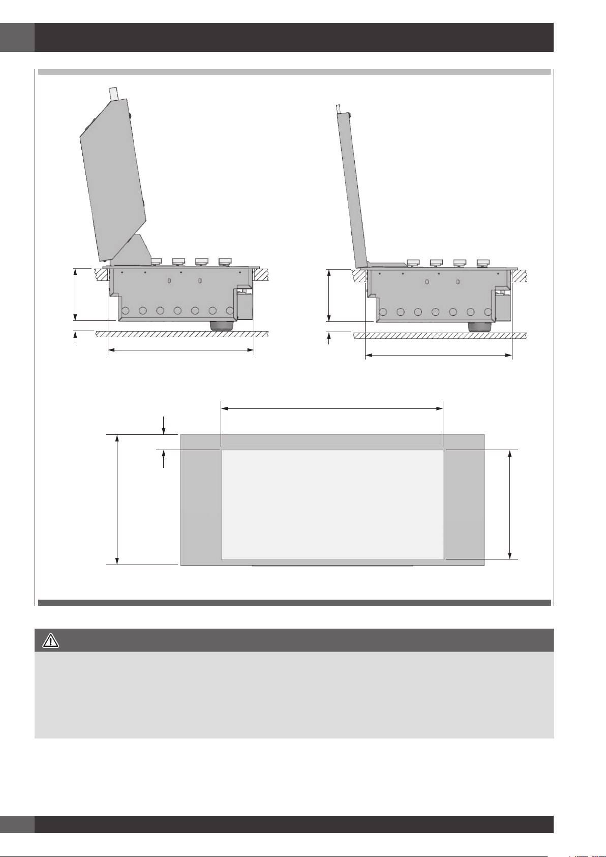
Installazione stile isola
• Se l’apparecchio viene installato in una montatura ad
isola, può essere collocato in posizione centrale. Fare
particolare attenzione alle dimensioni d’ingombro del
top dell’isola tenendo conto della cappa di cottura
aperta e della sporgenza. Vedere pag. 18.
• Le dimensioni richieste foro di inserimento sono di 1025
mm x 502 mm (vedere disegno).
Installazione in un Top inserito in un’apposito
contesto
• Il contesto deve essere realizzato in materiale non
combustibile.
• In caso di montaggio dell’apparecchio contro una
parete o una recinzione, è fondamentale aver cura di
assicurare l’isolamento dei materiali combustibili. Tutti i
materiali combustibili devono essere tenuti almeno 600
mm lontano dal barbecue.
• La profondità minima della superficie di montaggio (TOP)
è di 600 mm
• Le dimensioni richieste della foratura sono di 1025 mm x
505 mm (vedere disegno).
• Per i modelli con coperchio alto di cottura è richiesto
una spazio libero specifico sul retro del barbecue tra lo
schienale e la foratura del top, pari ad almeno 70 mm.
Questo affinché il coperchio alto disponga dello spazio
libero necessario per aprirsi.
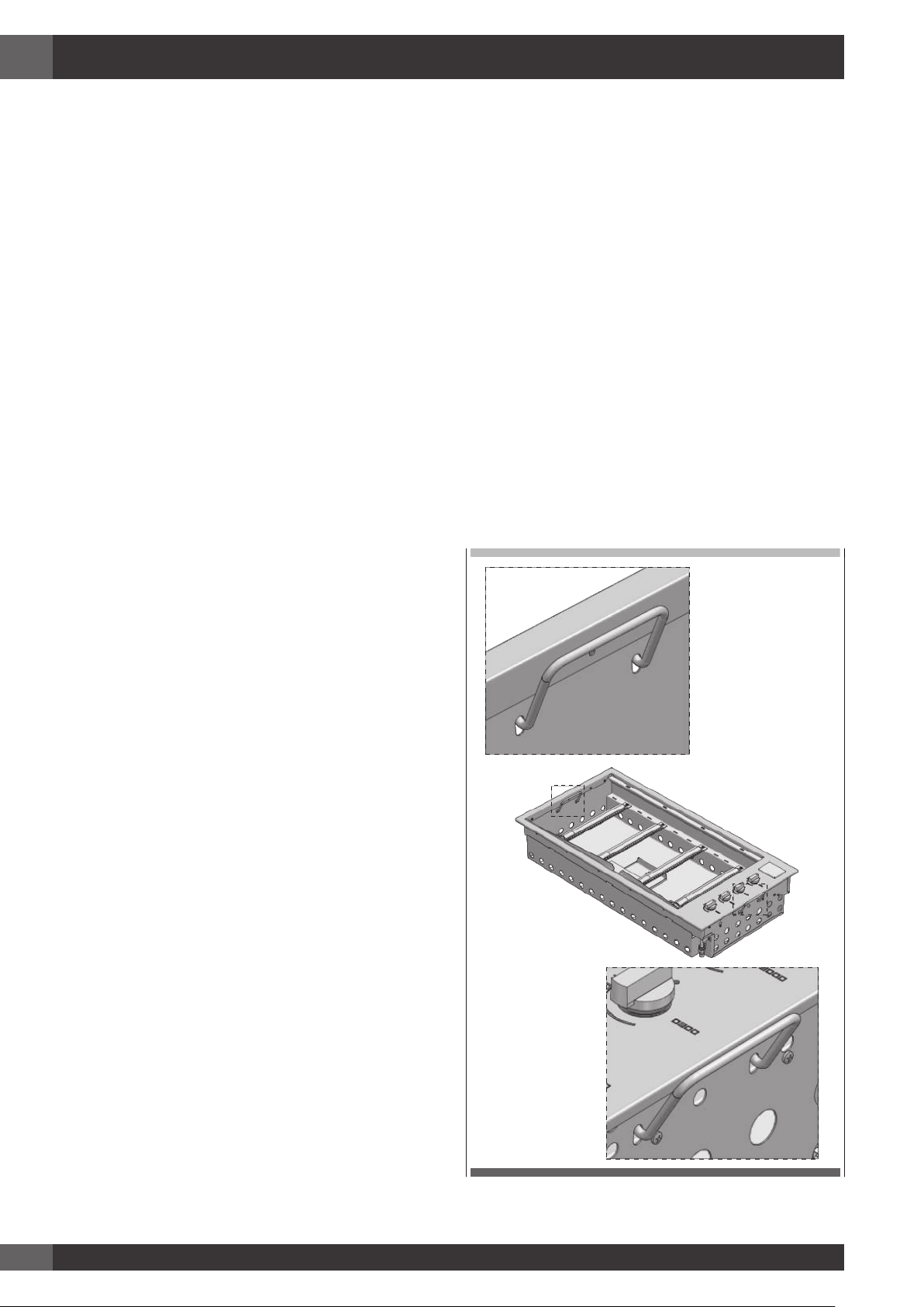
Per facilitare l’inserimento nel mobile, il prodotto e’ provvisto
di apposite maniglie di sollevamento (vedi figura sotto)
SX
DX
Page 19
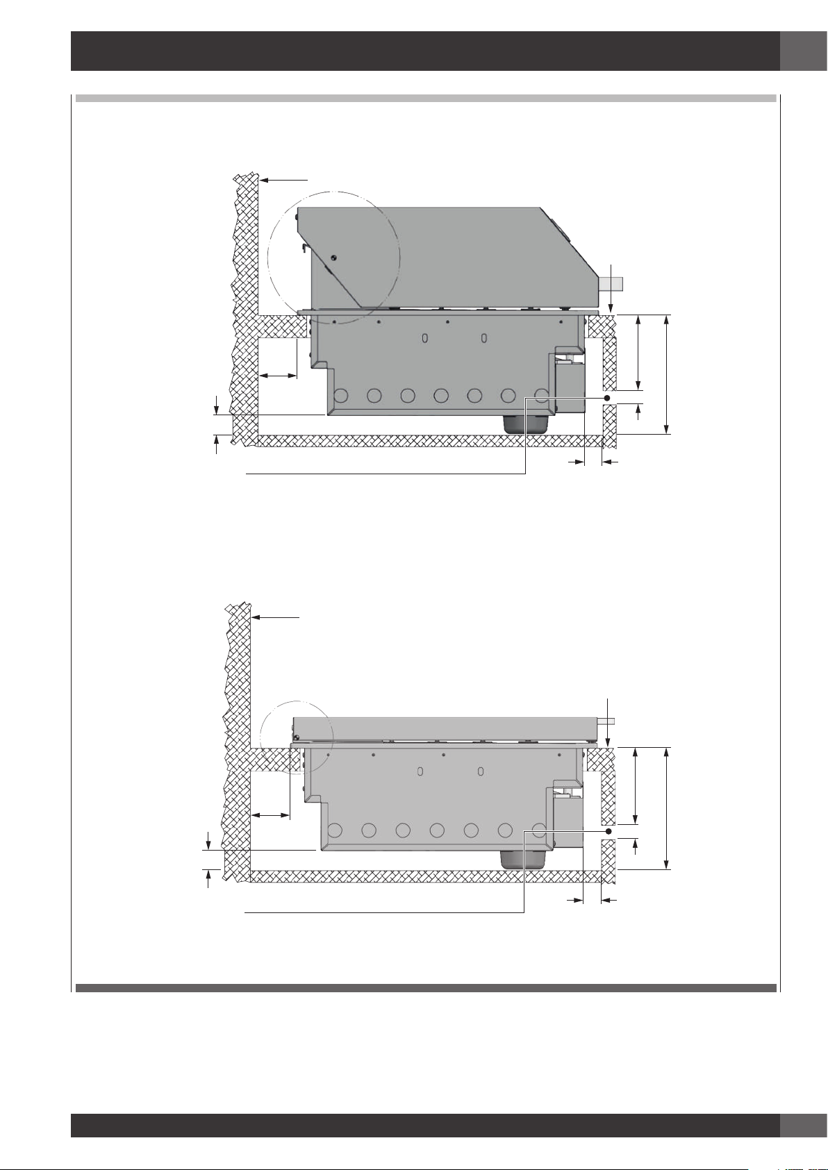
IT
17
Parete
Top
70
25 135
215
35
Apertura importante per areazione 25x700 mm
FRONTE
10
Parete
70
35
25 135
215
Top
Apertura importante per areazione 25x700 mm
10
FRONTE
Page 20
IT
18
505
35 180
505
35 180
Quota minima da parete
per giro coperchio
1025
600
70 min
505
Foro d’incasso
FRONTE
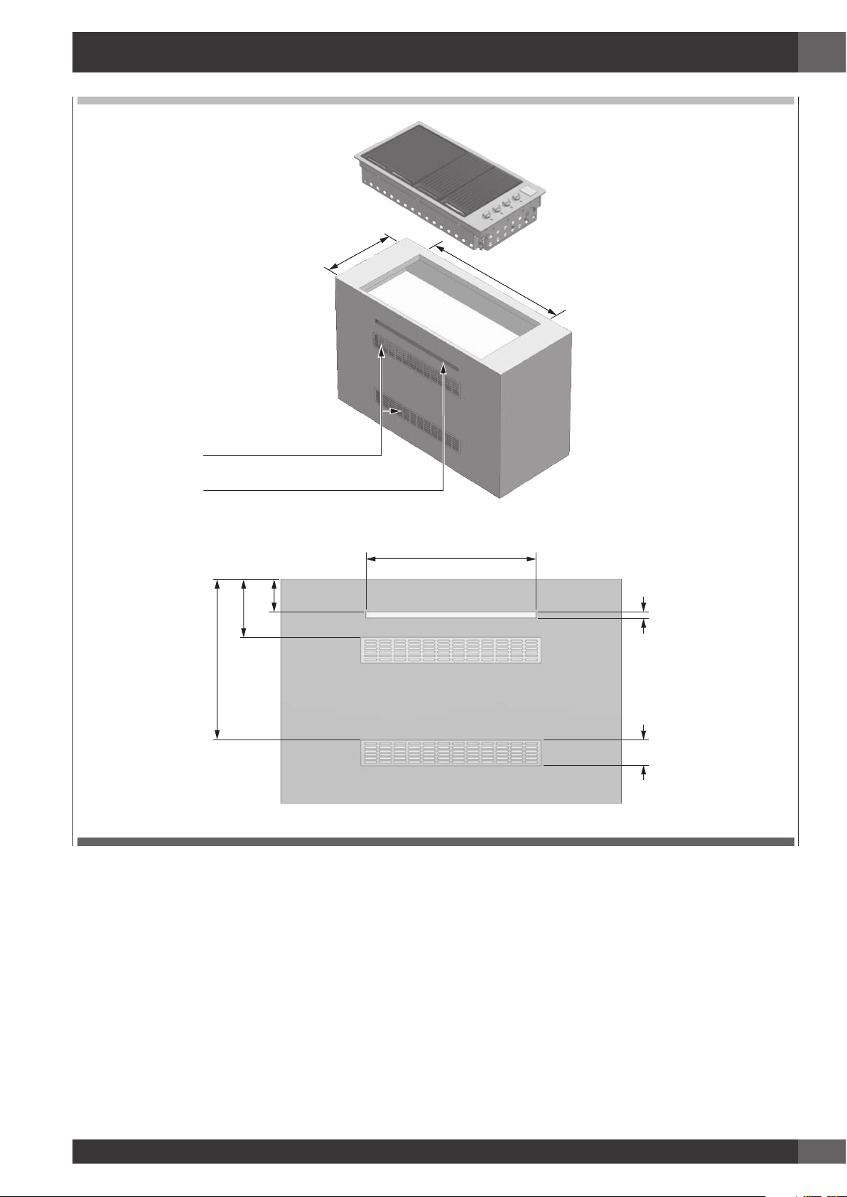
ATTENZIONE
• L’apparecchio richiede un’adeguata ventilazione. Deve essere prevista una superficie aperta come indicato sotto. Può
essere applicata una grata di aerazione se lo si desidera. Questa superficie di ventilazione consente l’ingresso dell’aria
nel vano per la corretta combustione dei gas e per la corretta aspirazione dei prodotti di combustione. Nel caso del
GPL, il gas è più pesante dell’aria; nell’eventualità di una fuga la bocchetta di ventilazione fa sì che il gas fuoriesca dal
vano. La bocchetta di ventilazione deve essere minimo di 700 mm x 25 mm e collocata in posizione centrale 135 mm
sotto la superficie di montaggio. (vedere disegno).
Page 21
IT
19
505
1025
apertura importante per areazione
griglie o fori d'areazione
700
135
240
660
25
105
Page 22
IT
20
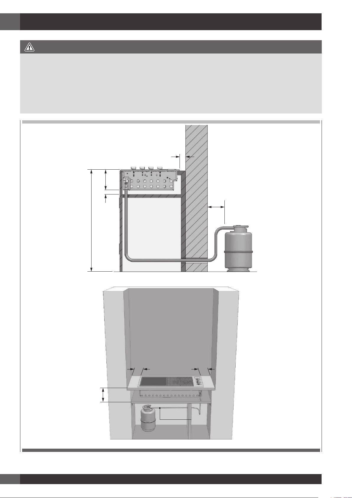
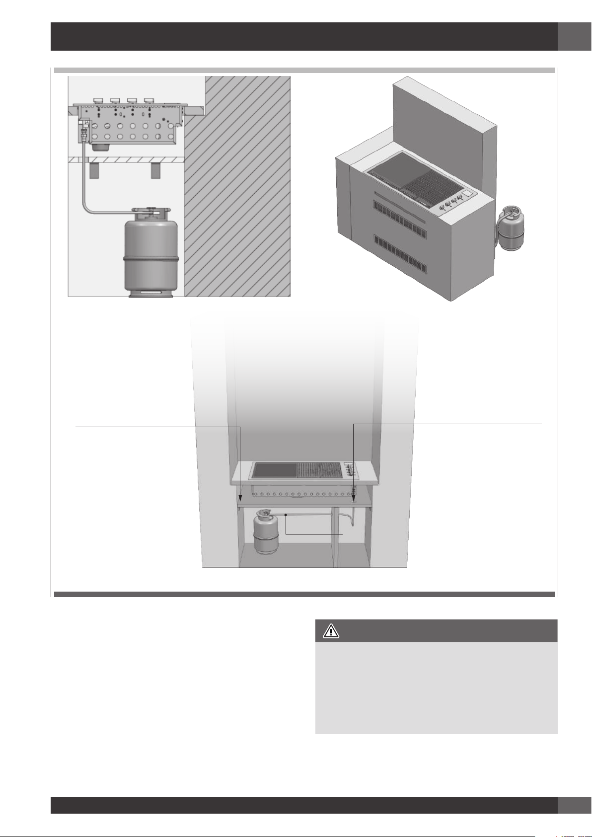
ATTENZIONE
• La bombola di GPL nel vano sotto l’unità barbecue, deve essere isolata dalla stessa per mezzo di un pannello non
combustibile. Il vano deve essere conforme ai requisiti della EN 498.
• I requisiti di ventilazione previsti dalla EN 498 per il ricovero delle bombole sono:
• In caso di struttura in lamiera o struttura simile impenetrabile, devono esserci aperture di ventilazione sulla parte superiore
e sul fondo del vano o della cavità, ognuna delle quali deve fornire una superficie libera di almeno 200 cm2 per ogni
bombola alloggiata le bocchette B servono inoltre come punto di ispezione nell’eventualità si usasse un tubo in gomma.
Distanza minima dalla parete
per apertura coperchio 55 mm
Min 20 mm
920
18035
Min 300 mm Min 300 mm
215 mm
MAX 1,5 mt
Page 23
IT
21
Barriera non combustibile
necessaria sotto barbecue
Tagliare un foro nella barriera
non combustibile solo per
passaggio del tubo
Parte frontale del vano rimossa per chiarezza illustrativa
MAX 1,5 mt
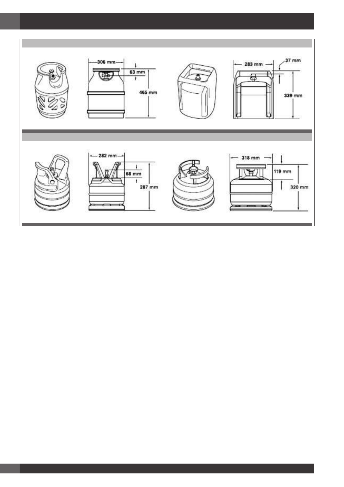
La bombola di GPL puo essere collegata all’interno del
vano portaoggetti del barbecue solo se ha le dimensioni
indicate nelle linee guida. L’utilizzo sicuro di una bombola
all’interno del vano portaoggetti del mobile che sostiene il
barbecue dipende da diversi fattori:
A) La base della bombola deve essere inserita correttamente
tra le piastre e trovarsi in posizione orizzontale sul pannello
di base.
Dimensioni della bombola
Altezza max 465 mm
Larghezza 289 mm - (sezione rettangolare) o 318 mm
(sezione circolare) massimo
B) Capacità della bombola max 6 kg
Sono disponibili diversi modelli di bombole di dimensioni
approvate (2).
AVVERTENZA
Se la bombola di GPL acquistata non presenta le
dimensioni richieste, non tentare di collegarla all’interno
del vano portaoggetti. Fissare la bombola sulla staffa
oppure posizionarla a terra. Il mancato rispetto di queste
istruzioni potrebbe danneggiare il tubo con conseguenti
incendi o esplosioni e causare lesioni gravi o mortali e
danni alle cose.
Page 24
IT
22
BP 5 kg BUTAGAZ 6 kg
CALOR 5 kg PRIMAGAZ 5.2 kg
Page 25
IT
23
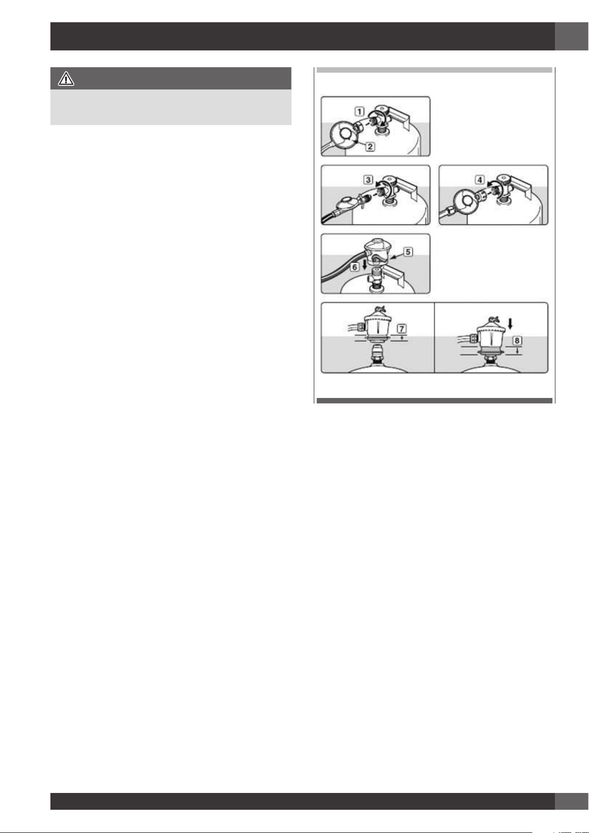
8 - Allacciamento della bombola di gpl
AVVERTENZA
Assicurarsi che la valvola della bombola GPL o del
regolatore sia chiusa.
Collegare la bombola di GPL.
Alcuni regolatori si collegano premendo ON e si scollegano
tirando OFF, mentre altri tipi di regolatori sono muniti di
dado con filettatura sinistra per il collegamento alla valvola
della bombola. Seguire le illustrazioni delle istruzioni di
collegamento specifiche per il regolatore.
a) Avvitare il regolatore alla bombola ruotando in senso
antiorario (1). Installare il regolatore in modo che il foro
di sfiato (2) sia rivolto verso il basso.
b) Avvitare il regolatore alla bombola ruotando in senso
antiorario (3) (4).
c) Assicurarsi che la leva del regolatore (5) sia abbassata
o in posizione off.
Premere il regolatore sulla valvola della bombola fino
a che non si avverte lo scatto che indica l’avvenuto
posizionamento (6).
d) Assicurarsi che la leva del regolatore sia in posizione
off. Alzare la ghiera del regolatore (7). Premere il
regolatore sulla valvola della bombola e tenere premuto.
Abbassare la ghiera (8). Se il regolatore non si blocca,
ripetere la procedura.
Page 26
IT
24
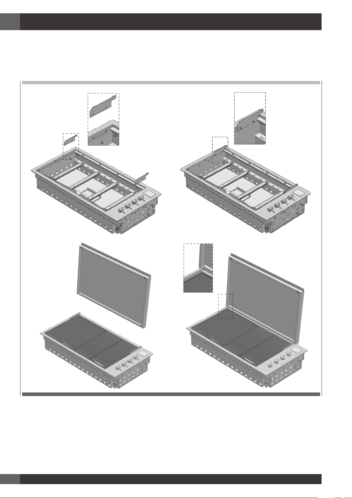
9 - Applicazione del coperchio
Applicazione del coperchio basso
• Togliere il coperchio sottile dall’imballaggio.
• Applicare le cerniere alla cornice esterna e fissarle con le apposite vite in dotazione.
SINISTRO
DESTRO
Page 27
IT
25
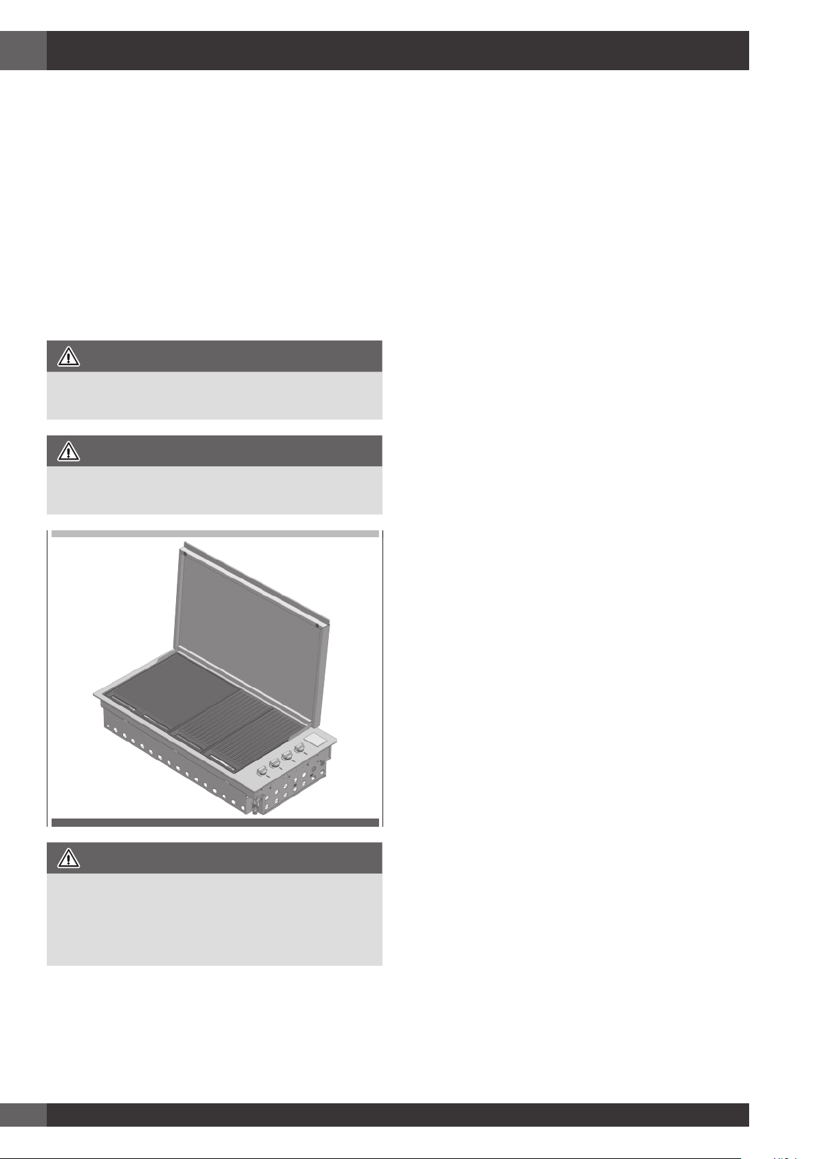
Applicazione del coperchio alto
• Togliere il coperchio alto dall’imballaggio.
• Estrarre la cerniera dal coperchio ed applicarla alla cornice esterna. Fissarla con le apposite viti in dotazione.
• Inserire il coperchio nelle apposite sedi della cerniera.
IMPORTANTE
Date le dimensioni della cappa di cottura, si consiglia che venga messa in posizione da due persone.
Durante il posizionamento del gruppo coperchio alto, fare particolare attenzione ad evitare di graffiare il profilo esterno.
Page 28
IT
26
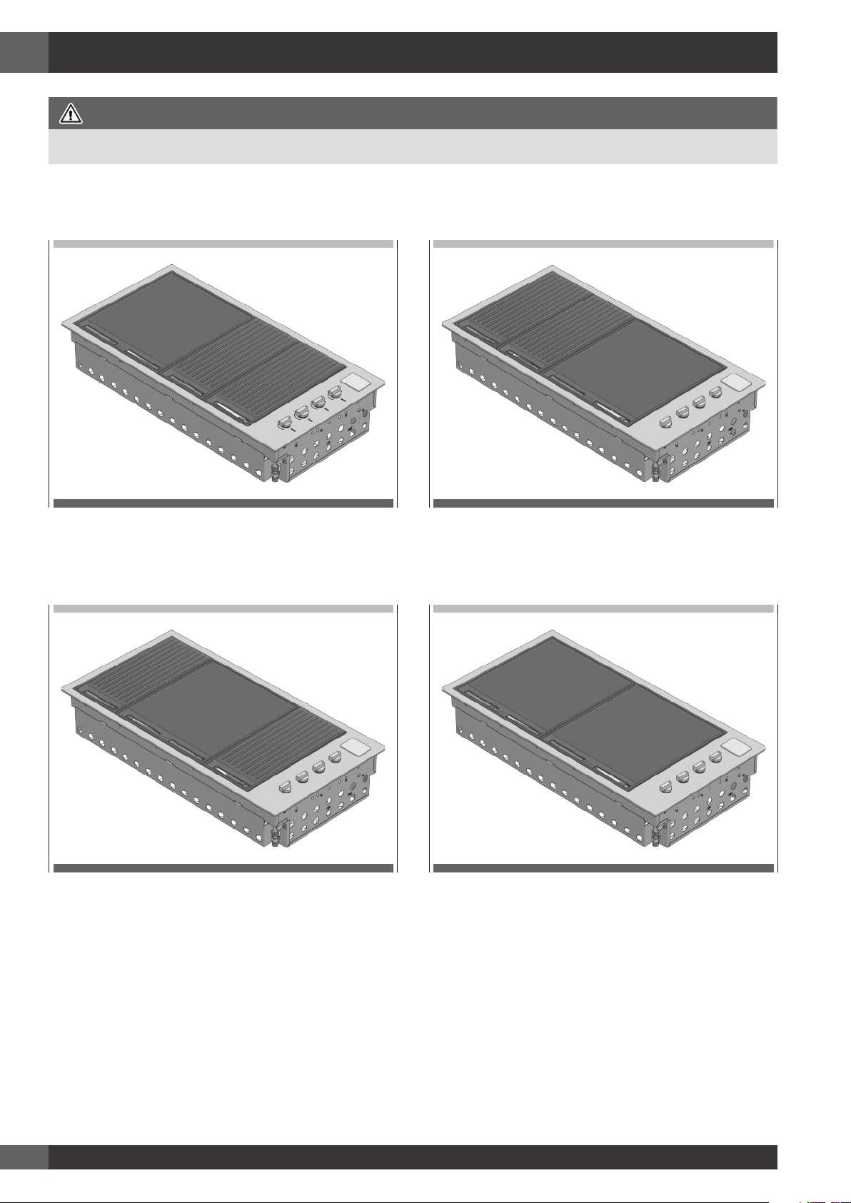
10 - Istruzioni d’uso
Piastra di cottura a sinistra, griglia a destra – orientamento
migliore per grigliare
Mezza griglia sinistra, piastra di cottura centrale, mezza
griglia a destra – orientamento migliore per arrostire
Griglie a sinistra, piastra di cottura a destra – orientamento
migliore alternativo per grigliare
Due piastre di cottura affiancate - disposizione opzionale
IMPORTANTE
Assicurarsi che i diffusori di fiamma siano posizionati sotto i pannelli delle griglie
Page 29
IT
27
Funzioni di controllo
Prima di accendere il barbecue:
• Controllare che tutti i tubi e raccordi del gas siano a
tenuta.
• Aprire il coperchio sottile o quello alto.
NOTA: Il coperchio sottile è progettato come copertura per
proteggere dagli agenti atmosferici. Il coperchio
non è concepito per essere usato come cappa di
cottura.
• Controllare che tutte le manopole di comando siano in
posizione di chiuso (O).
• Assicurarsi che le superfici di cottura siano pulite.
AVVERTENZA
Prima dell’uso, controllare che non vi sia grasso
accumulato nel vassoio inferiore. Rimuovere il grasso
eccessivo per evitare che prenda fuoco nel vassoio.
• Aprire la valvola di adduzione generale del gas.
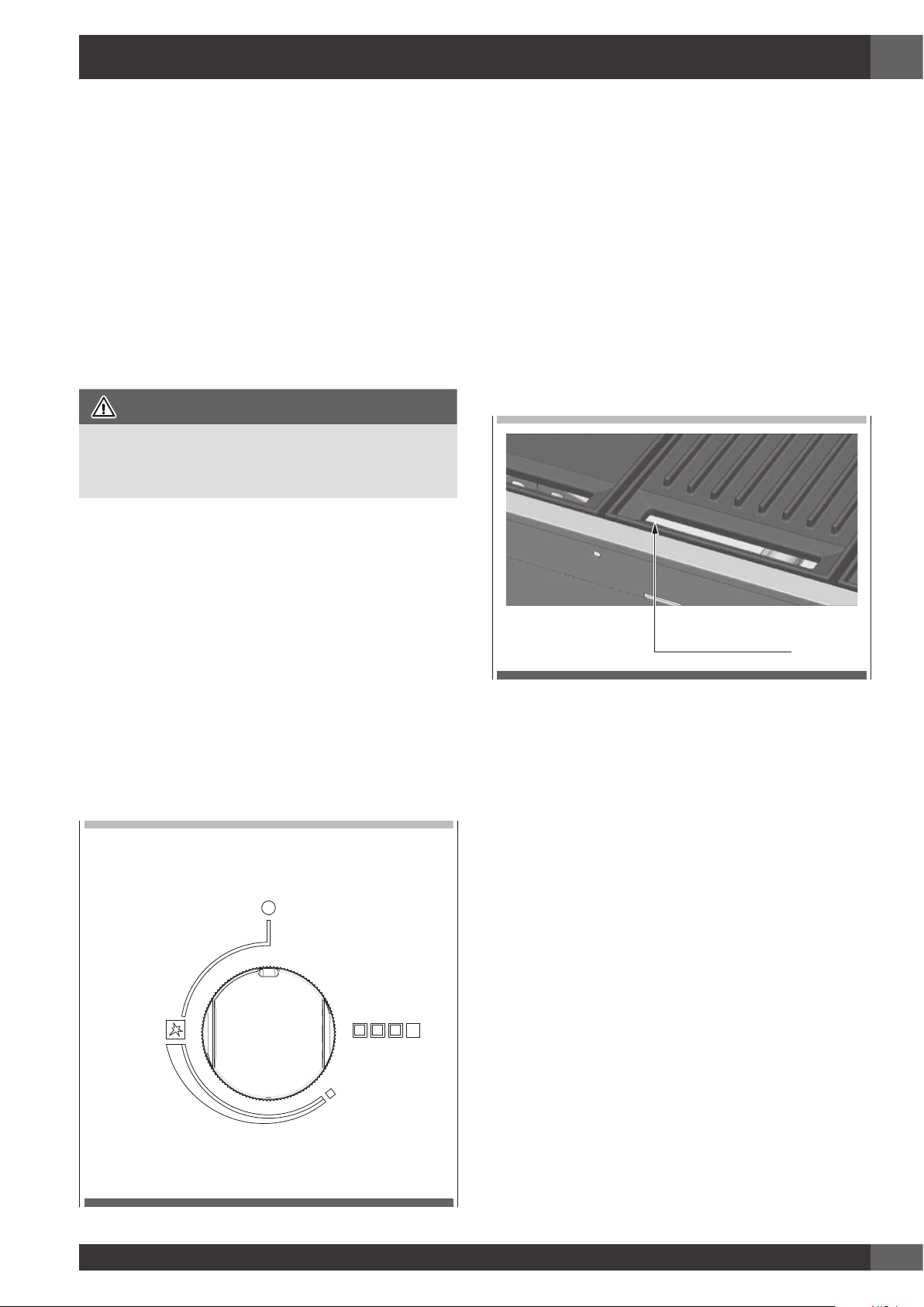
Istruzioni di accensione
• Non accendere i bruciatori con i piani cottura coperti.
• Per accendere un bruciatore, premere la manopola e
girarla in posizione ‘MAX’ (preriscaldamento rapido).
• Tenerla premuta per 5 secondi (contare fino a dieci),
rilasciarla e controllare la fiamma dalle feritoie sul
davanti.
• Se il bruciatore non si è acceso, girare la manopola in
posizione di chiuso (O). Lasciare che il gas si disperda,
quindi ripetere la procedura di accensione.
OFF
MAX
MIN
Accensione manuale
• Nel caso in cui il sistema automatico di accensione non
funzionasse, il barbecue può essere acceso manualmente.
• Per accenderlo manualmente, utilizzare un fiammifero
lungo (28cm). Far passare il fiammifero acceso tra le
fessure di ispezione sotto la parte anteriore delle piastre
di cottura, avvicinandolo al bruciatore, quindi girare la
manopola e tenerla premuta sul MAX (preriscaldamento
rapido) per effettuare l’accensione. Se l’accensione non
si verifica, chiudere la valvola di comando e attendere
per alcuni minuti che il gas si disperda prima di tentare
di nuovo di accendere il barbecue.
• Una volta acceso un bruciatore, ripetere la procedura
per gli altri se necessario.
Fessure di controllo
Preriscaldamento zone di cottura
• Questo barbecue è equipaggiato con bruciatori ad alta
potenza. Nella maggior parte delle condizioni sarà
necessario preriscaldare il barbecue solo per 5 minuti
prima che si possa iniziare la cottura.
• Come per la maggior parte delle cose, attraverso
l’esperienza maturata l’utente acquisisce dimestichezza
con l’efficacia e con l’intervallo necessario al
raggiungimento del tempo di preriscaldamento migliore
per ottenere la temperatura di cottura ideale. Non
dimentichiamo che ciò dipende anche dal tipo di cibo,
dal suo spessore e da come lo vogliamo cuocere.
• I test hanno dimostrato che si può abbassare la fiamma
dei bruciatori per una cottura soddisfacente.
• Se il barbecue è dotato di un coperchio sottile, è
consigliabile rimuoverlo in presenza di vento.
• Se l’unità non funziona correttamente, consultare il
capitolo “Risoluzione dei problemi”.
• Se si lascia che le zone di cottura si surriscaldino, si
svilupperà fumo in eccesso durante la fase di cottura,
con conseguente bruciatura del cibo che viene cucinato.
• Durante la cottura, evitare di sporgersi sulla griglia
aperta o di appoggiare le mani o le dita sul bordo del
vano di cottura.
Page 30
IT
28
• Nel caso di fiammate improvvise incontrollate,
allontanare il cibo dal fuoco fino a quando la fiamma
non si sarà smorzata.
• Per arrostire con il coperchio alto chiuso è sufficiente che
i 4 bruciatori siano regolati alla minima potenza (MIN)
per cuocere in modo soddisfacente
Per spegnere il bruciatore
• Quando la cottura è terminata, girare completamente
la manopola in senso orario in modo che l’indice sulla
manopola sia in posizione di chiuso (O).
AVVERTENZA
Ricordarsi di chiudere sempre la valvola gas della bombola
a fine utilizzo.
AVVERTENZA
L’utilizzatore si ricordi di escludere il gas prima di chiudere
il coperchio.
ATTENZIONE
IL COPERCHIO SOTTILE NON DEVE ESSERE CHIUSO
QUANDO I BRUCIATORI SONO IN FUNZIONE.
Se il coperchio viene chiuso mentre i bruciatori sono in funzione
si può provocare lo scolorimento e il danneggiamento del
coperchio e del barbecue.
Page 31

IT
29
Pulizia e cura dell’apparecchio
Perché il barbecue mantenga l’aspetto originario si consiglia
di pulire le zone cottura dopo ogni utilizzo.
ATTENZIONE
Assicurarsi che il barbecue sia spento e si sia raffreddato prima
di eseguire le istruzioni riportate di seguito.
Pulizia delle parti di cottura
• Togliere dalla griglia e dalla piastra di cottura tutti i
materiali solidi e il grasso in eccesso usando un raschietto
o una spazzola metallica con setole d’ottone.
• Assicurarsi che tutte le superfici vengano asciugate con
un panno pulito e asciutto
Altre superfici in acciaio inossidabile
ATTENZIONE
Non usare detergenti abrasivi o caustici, pagliette o raschietti
metallici su queste superfici in acciaio inossidabile, perché
possono graffiare e danneggiare in permanenza il barbecue.
• Lavare tutte le parti in acciaio inossidabile, compresi
il coperchio sottile, coperchio alto e le manopole di
comando, con uno strofinaccio morbido usando acqua
calda saponata.
• Pulire le superfi accertandosi di strofi nare/asciugare
nella direzione della grana per non rovinare l’acciaio
inox.
• L’interno del barbecue può essere pulito con un panno
morbido bagnato in acqua calda saponata. Il pannello /
vassoio anteriore collocato all’interno è asportabile per
una facile pulizia.
• Assicurarsi che tutte le superfici vengano asciugate con
un panno pulito e asciutto
Pulizia delle griglie di cottura in ghisa
• Pulire con una spazzola adatta con setole di ottone. Se
necessario, rimuoverle dal barbecue, lavarle con acqua
saponata tiepida, sciacquarle con acqua ed effettuare
un’attenta asciugatura.
IMPORTANTE
A fine cottura e pulizia, le griglie in ghisa vanno oliate.
Utilizzando un panno o un pennello, applicate su tutto
il pezzo un sottile strato di olio vegetale. Quindi, con
un panno strofinate come se doveste ripulire tutto l’olio
appena messo.
Pulizia delle griglie in acciaio inossidabile
• Togliere dalla griglia e dalla piastra di cottura tutti i
materiali solidi e il grasso in eccesso usando un raschietto
o una spazzola metallica.
• Per facilitare la pulizia, le due metà della griglia possono
essere rimosse con la piastra di cottura. Per le macchie
ostinate, immergere semplicemente le parti della griglia e
la piastra in acqua calda saponata prima di risciacquarle
con cura.
• Assicurarsi che tutte le superfici vengano asciugate con
un panno pulito e asciutto.
AVVERTENZA
Fare particolare attenzione (in special modo quando si pulisce
sulle manopole e attorno ad esse) ad evitare che acqua e
residui di sapone entrino nel pannello di controllo in cui si
trovano i rubinetti o nei bruciatori. Fare attenzione anche a non
toccare l’elettrodo di accensione e termocoppia. Tra l’elettrodo
e i bruciatori deve essere mantenuta una distanza di 3 mm
(vedere disegno pagina seguente).
3 mm
11 - Pulizia e cura
Page 32

IT
30
3 mm
Pulizia della vaschetta di raccolta olio
Il barbecue integrato ha un sistema di gestione dell’olio,
che usa un canale per convogliare tutto l’olio verso la parte
anteriore in una vaschetta di raccolta facilmente amovibile,
la vaschetta deve essere pulita dopo ogni utilizzo.
• Per estrarre la vaschetta, attendere che l’apparecchio
e la vaschetta si raffreddi, togliere le griglie, spostare
il cassetto e sollevare verso l’alto la vaschetta; smaltire
poi il contenuto raccolto in modo responsabile. Lavare
la vaschetta di raccolta in acqua calda saponata o, se
volete, potete metterla in lavastoviglie.
Bruciatori
I bruciatori vanno controllati almeno una volta all’anno e
puliti se necessario. Ispezionare i bruciatori per accertarsi
che non si siano depositati dei residui e che gli attacchi del
gas siano liberi.
SUGGERIMENTI E INFORMAZIONI
Nota speciale sulla “colorazione tè”
Talvolta le superfici di acciaio inossidabile sono affette da
un’alterazione cromatica chiamata “colorazione tè”. Questa si
verifica solitamente nelle zone in cui si impiega un calore molto
forte e può essere facilmente rimossa usando detergenti specifici
per l’acciaio inossidabile. Per ottenere i risultati migliori, si
consiglia di usare regolarmente detergenti specifici su tutte le
parti in acciaio inossidabile. Questi detergenti sono disponibili
in quasi tutti i negozi di ferramenta ma anche nei supermercati.
Nota speciale sull’acciaio inossidabile
I pannelli di acciaio inossidabile possono deformarsi durante
l’uso ma riprendono la forma normale una volta raffreddati.
Page 33

IT
31
Sistema di accensione
Per cambiare la batteria togliere il coperchio copri batteria
sollevando dal lato sinistro lo sportellino del porta batteria
ed estrarre la batteria. Sostituirla con una batteria D nuova
e riposizionare il coperchio. Fare una prova premendo la
manopola; si dovrebbe udire un clic sonoro.
Aperture di ventilazione
Le aperture di ventilazione del vano di installazione devono
essere controllate prima di ogni utilizzo dell’apparecchio,
per assicurarsi che non presentino ostruzioni che possono
ostacolare il libero flusso dell’aria.
12 - Manutenzione
Page 34

IT
32
PROBLEMA
CAUSA POSSIBILE
RIMEDIO
Il barbecue non si accende Assenza di gas Controllare che la valvola di isolamento sia aperta
(ON)
Bombola del gas vuota - riempire o cambiare la
bombola
Il sistema di accensione non
funziona
Controllare la batteria – si dovrebbe udire un clic
sonoro quando si preme la manopola
Sostituire la batteria
Accendere il barbecue manualmente
Rubinetto del gas regolato
troppo alto
Pulire e asciugare delicatamente l’elettrodo
assicurandosi che la posizione sia corretta
Fumo eccessivo emesso dalla
superficie di cottura
Valvola del gas regolata troppo
alta
Abbassare il gas o spegnere alcuni bruciatori
Odore di gas
NON CERCARE DI
ACCENDERE L’PPARECCHIO
Fuga di gas Chiudere il gas con le valvole di isolamento
Verificare se ci sono fughe, stringere i raccordi
Se il problema persiste chiamare l’assistenza
13 - Risoluzione dei problemi
Page 35

IT
33
Page 36

IT
34
DICHIARAZIONE DEL PRODUTTORE
Con la presente il produttore dichiara che i prodotti di questo catalogo rispondono, a secondo delle tipologie, ai requisiti
fondamentali richiesti dalle Direttive Europee e perciò il prodotto è stato contrassegnato col marchio CE e per esso è stata
emessa la dichiarazione di conformità, a disposizione degli organi preposti al controllo del mercato.
SMALTIMENTO DEGLI APPARECCHI USATI
Al termine del periodo di utilizzo è vietato smaltire questi apparecchi elettrodomestici con i normali rifiuti urbani, deve bensì
essere consegnato al punto di raccolta e riciclaggio delle apparecchiature elettriche ed elettroniche. Ne informa il simbolo
riportato sul prodotto, sul manuale di istruzioni o sull’imballaggio.
I materiali impiegati nell’apparecchio possono essere riutilizzati in conformità alla loro destinazione.
Grazie al riutilizzo, al riciclo dei materiali o ad altre forme di riutilizzo degli apparecchi inservibili,
darete il Vostro contributo alla protezione del nostro ambiente naturale.
Le informazioni relative ai punti di smaltimento degli apparecchi inservibili vi saranno fornite dalle competenti autorità
territoriali.
Il produttore declina ogni responsabilità per inesattezze contenute nel presente catalogo a causa di errori tipografici. Ci
riserviamo il diritto di apportare delle modifiche migliorative o indispensabili ai prodotti senza alterarne le specifiche essenziali.
I prodotti possono subire delle modifiche a seguito di richieste migliorative e normative CE.
SERVIZIO ASSISTENZA TECNICA: 800.305.302
Page 37

EN
1
Congratulations
Congratulations and thanks for choosing our integrated
barbecue. We are confident that it will be a pleasure for you
to use our new barbecue. Before using the barbecue, we
recommend reading the entire user guide, which provides a
description of the barbecue and its functions. To avoid those
risks that are always present when using a gas appliance,
it is important to install it correctly and carefully read the
safety instructions in order to avoid misuse and hazards.
We recommend you keep this instruction booklet for future
reference and pass it to any subsequent owners. After
removing the barbecue from its packaging, check to see
that it is not damaged. If in doubt, do not use the appliance
and contact your nearest customer service centre.
Suggestion for the environment Disposal information
for users
• Most of the packaging material is recyclable. These
materials should be disposed of through a local recycling
centre or by putting them in appropriate collection
containers.
• If you want to discard the product, contact your local
authorities and ask about the correct method of disposal
TABLE OF CONTENTS PA G E
1 - Product description 2
2 - Components 4
3 - Important safety instructions 5
Use 5
The manufacturer’s liability: 7
4 - Assembling the barbecue 8
5 - Characteristics of gas in different countries 10
Adapting to different types of gas 11
Gas connection 12
Rigid and semi-rigid metal and rubber hose
connection 12
6 - Gas cylinder safety information 14
Leak testing procedure 14
7 - Installation instructions and warnings 15
Selection of the point of installation 16
Installation compartment 16
Island-mounted 16
Installation in a counter in a special context 16
8 - Connection of the LPG cylinder 23
TABLE OF CONTENTS PA G E
9 - Application of the cover 24
Application of the low cover 24
Application of the high cover 25
10 - Usage instructions 26
Control functions 27
Ignition instructions 27
Manual lighting 27
Pre-heating cooking areas 27
To turn off the burner 28
11 - Cleaning and care 29
Care and cleaning of the appliance 29
Cleaning of cooking parts 29
Other stainless steel surfaces 29
Cleaning the cooking grills made of cast iron 29
Pulizia delle griglie in acciaio inossidabile 29
Cleaning the grease drip pan 30
Burners 30
12 - Maintenance 31
Ignition system 31
Ventilation openings 31
13 - Troubleshooting 32
Page 38

EN
2
1 - Product description
BARBECUE MOD. FOBQ 1000 G MBK
LOW LID MOD. FOBQ LL 1000 MBK
BARBECUE MOD. FOBQ 1000 G X
LOW LID MOD. FOBQ LL 1000 X
7
1
2
4
3
6
5
7
1
2
4
3
6
5
Integrated barbecue with thin cover
1. Thin cover 1. Thin cover
2. Battery compartment cover 2. Battery compartment cover
3. Gas connection point 3. Gas connection point
4. Burner controls 4. Burner controls
5. Cast iron grills group (2 set) 5. Stainless steel grill group (2 set)
6. Cooking plate 6. Cooking plate
7. Removable oil collection drip plan located in front
of the cooking surface (not shown)
7. Removable oil collection drip plan located in front
of the cooking surface (not shown)
8. Flame diffusers (2 pcs.) located under the grills (not
shown)
8. Flame diffusers (2 pcs.) located under the grills (not
shown)
Page 39

EN
3
BARBECUE MOD. FOBQ 1000 G MBK
HIGH LID MOD. FOBQ LL 1000 MBK
BARBECUE MOD. FOBQ 1000 G X
HIGH LID MOD. FOBQ HL 1000 X
16
9
11
13
12
15
14
10
16
9
11
13
12
15
14
10
Integrated barbecue high cover
9. High cover 9. High cover
10. Heating racks 10. Heating racks
11. Battery compartment cover 11. Battery compartment cover
12. Gas connection point 12. Gas connection point
13. Burner controls 13. Burner controls
14. Cast iron grill group (2 set) 14. Stainless steel grill group (2 set)
15. Cooking plate 15. Cooking plate
16. Removable oil collection drip plan located in front
of the cooking surface (not shown)
16. Removable oil collection drip plan located in front
of the cooking surface (not shown)
17. Flame diffusers (2 pcs.) located under the grills (not
shown)
17. Flame diffusers (2 pcs.) located under the grills (not
shown)
Page 40

EN
4
QTY DESCRIPTION QTY DESCRIPTION
1
Burner box and external
profile
1
Large cast iron
cooking plate
4 Burners 1
Stainless steel
cooking plate
2 Flame diffusers 2 Cast iron grills groups
2 Flame diffusers (optional) 2
Stainless steel
grills group
1 Oil tray
CONFIGURATION 1
QTY DESCRIPTION
1 High cover for cooking
CONFIGURATION 2
QTY DESCRIPTION
1 Low cover
2 - Components
Page 41

EN
5
Use
Carefully read the user manual and keep it in a handy place for future reference.
Below, we explain the meaning of the symbols used in this manual:
ATTENTION
This symbol indicates information relating to the user’s personal safety
WARNING
This symbol indicates information on how to prevent damage to the appliance
TIPS AND INFORMATION
This symbol indicates tips and information about the use of the appliance
SUGGESTION FOR THE ENVIRONMENT
This symbol indicates information for the economical and ecological use of the appliance
PROHIBITION
This symbol indicates a prohibited action
ATTENTION
The appliance MUST only be installed and serviced by qualified and authorized personnel.
Improper installation, modification, adjustment or maintenance can cause personal injury or
property damage.
Contact your nearest Service Centre for further information.
3 - Important safety instructions
For your own safety, you should read this manual before
operating the barbecue.
Page 42

EN
6
PROHIBITION
• Do not lean over barbecue while lighting.
• Do not leave the barbecue unattended
when it is on.
• Do not delay ignition once the gas is
opened.
• Do not store or use aerosol sprays near the
barbecue.
• Do not store inflammable liquids near the
barbecue.
• Do not use abrasive or caustic detergents
on the barbecue.
• Do not operate the barbecue with the cover
closed.
• Do not attempt to disassemble or adjust the
control valves.
• Do not attempt to disassemble or adjust
the cylinder regulator (not supplied) but, if
necessary, replace with a new one.
• Do not use an open flame to check for leaks.
• Do not modify the structure of the appliance
and do not modify the dimensions of the
injector orifice.
PROHIBITION
• Do not obstruct the ventilation openings of
the barbecue.
• Do not allow children to operate the
barbecue or play near it.
• Do not use the barbecue if inflammable
materials are within a radius of about 60
cm from the top, bottom, rear or sides of
the appliance.
• Keep any electrical wires and fuel hoses
away from hot surfaces.
• Never store a spare gas cylinder near the
barbecue.
• This appliance reaches high temperatures.
Be especially careful when children and
elderly persons are present
• Do not move the barbecue when it is on.
• Wear protective gloves when using the
barbecue.
• Keep children under the age of eight years
away, if not constantly supervised.
• Never attempt to extinguish a flame/fire
with water: turn off the appliance and cover
the flame with a cover or a fire blanket.
NOTE FOR THE INSTALLER: THIS MANUAL MUST BE LEFT WITH THE OWNER FOR FUTURE
REFERENCE
ATTENTION
IF YOU SMELL GAS, do not try to light the barbecue. Perform the leak test procedure described in
this manual. Locate the leak and tighten the leaking fitting; if it is the cylinder fitting, also replace
the gasket seal.
If the leak persists, turn off the gas supply and call for technical assistance.
Page 43

EN
7
PROHIBITION
• Be careful when handling gas cylinders
even if they appear empty, in compliance
with current safety rules.
• Do not use dented or rusty gas cylinders
• Do not disconnect the gas cylinder from
the appliance when it is on. Perform any
service on the gas cylinder far away from
the appliance.
• Only turn the burners on with the cover lifted
• If the knob becomes difficult to rotate, have
the taps checked by an authorized service
centre.
• Lower the cover, accompanying it with
your hand and make sure that nothing is
obstructing its proper closure.
• When cooking with the cover closed
keep an eye on the thermometer: if the
temperature exceeds 350 °C, lift the cover
to prevent dangerous overheating.
• Do not leave objects on the cooking
surfaces.
• Never use the appliance to heat the area.
• Always close the valve of the gas cylinder
after use.
The manufacturer’s liability:
The manufacturer will not be liable for personal
injury or property damage caused by:
• any use of the appliance other than
anticipated;
• failure to follow the instructions of the user
manual;
• tampering with any part of the appliance;
• use of other than original parts.
Page 44

EN
8
4 - Assembling the barbecue
Tools needed for assembly:
- Phillips screwdriver
1. Remove all components from the box.
BACK
FRONT
2. Place the flame diffusers in the desired positions (under
the points (A) in which the grill sections will be placed)
and attach the rear edge of the flame diffuser to the rear
of the body of the barbecue.
BACK
FRONT
3. Apply the oil drip pans to the front of the barbecue.
BACK
FRONT
BACK
FRONT
4. Place the cooking plate and grill sections in the desired
positions, making sure that the flame diffusers are under
the grill sections.
NOTE: Make sure that the grill groups are correctly oriented
so that the surface of the grill is tilted forward to
allow the oil to drain into the drip pans.
CAST IRON GRILLS GROUPS
Page 45

EN
9
STAINLESS STEEL GRILLS GROUPS
FRONT
BACK
5. After installation in the counter, connect the thin cover
or cooking hood area as described in the chapter
“Application of the thin cover or cooking hood” in this
manual.
Page 46

EN
10
CATEGORY GAS AND PRESSURES
COUNTRIES OF DESTINATION
AT BE CY HR DK EE FI FR DE GR IE IS IT LV LT LU MT NO NL PT PL GB CZ RO SK SI ES SE CH TR HU
I3+ G30 /G31 = 28-30/37 mbar • • • • • • • • • • • • • • •
I3B/P(30) G30 /G31 = 30 mbar • • • • • • • • • • • • • • • • • • •
I3B/P(37) G30 /G31 = 37 mbar •
I3B/P(50) G30 /G31 = 50 mbar • • • • •
2H G20 = 20 mbar • • • • • • • • • • • • • • • • • • • • • •
2E G20 = 20 mbar • • • • •
2E+ G20 = 20 mbar • •
2L G25 = 25 mbar •
2LL G25 /20 mbar • •
2H(25) G20 /25 mbar •
2S G25.3 /25 mbar • •
2Lw G27 /20 mbar •
2Ls G2.350/13 mbar •
G20-20
cat. 2H, 2E, 2E+
G20-25
cat. 2H(25)
G25-20
at. 2LL
G25-25
cat.2L
G25.3
cat.2S
G27
cat.2Lw
G2.350
cat.2Ls
G30 /G31
cat. I3+
G30 /G31
cat. I3B/P (30)
G30 /G31
cat. I3B/P (37)
G30 /G31
cat. I3B/P (50)
Nominal heat input (kW) 15,2 15,2 15,2 15,2 15,2 15,2 15,2 15,2 15,2 15,2 15,2
Injector diameter (1/100mm) 135 130 155 145 145 155 194 94 94 89 83
Number of injectors 4 4 4 4 4 4 4 4 4 4 4
Pressure (mbar) 20 25 20 25 25 20 13 28..30/30..37 30 37 50
Maximum consumption (l/h) 1448 1448 1684 1684 1683 1766 2011 1106 1106 1106 1106
Primary air regulation (mm)
(X) see fig. page 12
1 1 1 1 1 1 1 All open All open All open All open
5 - Characteristics of gas in different countries
Page 47

EN
11
Adapting to different types of gas
If the appliance is configured for a different type of gas than
that available, you have to replace the injectors with ones
corresponding to the type of gas to be used (see tables on
the preceding pages). The replacement will be made using
an adequate 7 mm key after having lowered the burners as
in the following images. After replacing the injector, regulate
the air to 1mm for natural gas and to the maximum if LPG.
To adjust the minimum, after lighting the burner, remove the
knob and the gasket below and rotate the screw of the tap
(B - see page 12), which should be totally closed for
LPG and opened about 3/4 turn for natural gas, keeping
in mind that a flame lower than 3 mm may not even be
“perceived” by the thermocouple of the tap. After regulating
the minimums, replace the gaskets and knobs.
1 - Unscrew the fixing screws of the burner.
BACK
FRONT
2 - Lower the burner and replace the injector.
FRONT
BACK
Page 48

EN
12
X
NOTES
• The appliance MUST only be installed and serviced by
qualified and authorized personnel.
• The product is exclusively intended for outdoor use.
• The product must be installed according to the instructions,
which require ventilation openings to allow the grill to work
properly. The lack of adequate ventilation to supply air to
the appliance can lead to poor operation of the burners or
excessive heat build-up in the installation compartment.
• The unit’s ventilation openings must not be covered during
installation.
Gas connection
Connect the appliance to the cylinder or system according to
the requirements of current law, making sure that the appliance
is configured for the type of gas available. If not, see: “Adapting
to different types of gas”. Also check that the feed pressure falls
within the values shown in the table: “Gas specifications”.
Rigid and semi-rigid metal and rubber hose
connection
Make the hook-up with metal fittings and pipes (even flexible
hoses) so as not to stress the components inside the appliance.
A rubber hose connection complies with current law only if
the hose can be inspected along its entire length and easily
replaced near the expiration indicated on the hose.
NOTE: - After installation, use soapy water to check the perfect
seal of the entire connection system. DO NOT USE AN OPEN
FLAME TO CHECK THE GAS SEAL.
Page 49

EN
13
Detail of the gas connection
52 47488
With note: natural gas connection NG.
Page 50

EN
14
6 - Gas cylinder safety information
• When converted for the use of universal
LPG, the appliance is designed to use
different types of cylinders depending on
the installation made. See the chapters on
Installation Preparation and Connection of
the cylinder.
• The gas cylinder must be manufactured and
marked in accordance with the specifications
for LPG cylinders.
• The shut-off valve must be closed when the
appliance is not in use.
• The gas cylinders must be kept in an approved
housing out of the reach of children.
• When you disconnect the gas cylinder, make
sure all the control valves are in the “OFF”
(O) position.
• Before disconnecting, remove the cylinder
from any housing in which it may be located.
• When you reconnect the hose to the cylinder,
make sure all the connections are tight before
placing it back in its compartment.
• After each connection of a cylinder, perform
a leak test as described below.
Leak testing procedure
• Make sure that all the gas taps are in the
“OFF” (O) position.
• Mix a solution of water and detergent or
soap in a small container.
• After connecting the hose, open the valve on
the gas cylinder or gas system tap.
• Using a brush, paint the solution on the gas
connection points and check for bubbles.
• Bubbles indicate a leak.
• Close the valve and tighten the fitting, possibly
inserting a new gasket. Repeat the leak test.
• If the leak persists, turn off the gas and contact
an authorized gas system maintenance
technician to repair the leak.
Page 51

EN
15
7 - Installation instructions and warnings
ATTENTION
• The appliance must only be used above ground level,
in open air and natural ventilation without stagnant
areas where leaking gas and combustion products are
rapidly dispersed by the wind or natural convection.
This barbecue is designed exclusively for outdoor use.
Refer to the drawings below.
• Never install the barbecue inside buildings, garages,
sheds or covered walkways, or in a boat, camper or
caravan. This prevents the creation of fires or carbon
monoxide with toxic effects or asphyxiation.
• The compartment in which the appliance is installed
must conform to one of the following requirements:
ATTENTION
• A compartment with walls on all sides, but with at least
one permanent opening at ground level and without
upper cover.
• In a partial compartment that has a top cover and not
more than two walls.
• In a partial compartment that has a top cover and
not more than two walls; in this case, the following
principle applies:
• At least 25% of the total area of the walls is completely
open and at least 30% of the remaining area of the
walls is open and free.
• In the case of balconies, at least 20% of the total area
of the side, front and rear walls must be and remain
open and free.
External surface area example 1
External surface area example 2
External surface area example 3
both ends open
External surface area example 4
open side for at least 25% of the total area of the walls in total 30% or more of the
remaining surface of the walls is open and free
External surface area example 5
open side for at least 25% of the total area of the walls in total 30% or more of the
remaining surface of the walls is open and free
Page 52

EN
16
Selection of the point of installation
• The appliance must not be installed on combustible
materials. The minimum distance from combustible
materials is 600 mm.
• The free space above the cooking surface with respect to
combustible materials must be at least 600 mm.
• The appliance must be installed in accordance with
standards and local deviations.
• When using LPG, ventilation must be ensured in the
compartment. The gas is highly explosive and can cause
serious personal injury and property damage if it is left to
accumulate and then ignited.
• The barbecue is designed to be mounted in a counter
with a minimum depth of 600 mm.
• Avoid locations exposed to the wind as this may affect
cooking and the efficiency of the burners. If you cannot
avoid such a location, screens may be necessary.
Installation compartment
• The barbecue requires a non-combustible barrier beneath
it to prevent reaching an excessive temperature in
compliance with the current UNI EN 498 standard. The
panel that acts as a barrier must be positioned 30/35
mm below the base of the unit.
• The installation compartment must be made of noncombustible materials. Materials suitable for its
construction include brick, granite, marble, Hardiplank®
and Villaboard® on a metal or brick structure.
• The appliance requires ventilation openings in the
front wall of the compartment. See the drawing page
“RIMANDO 2” a pagina 19.
• The appliance unit can be mounted in an island counter
or a counter with splash guard. Read the specific
requirements for each type of mounting.
Island-mounted
• If the appliance is installed in an island, it can be placed
in the centre. Pay particular attention to the overall
dimensions of the top of the island, taking into account
the open cooking hood and its projection. See page
18.
• The required dimensions of the cut-out are 1025 mm x
502 mm (see drawing). .
Installation in a counter in a special context
• The context must be made of non-combustible material.
• When mounting the appliance against a wall or a
fence, it is essential to insulate combustible materials.
All combustible materials must be kept at least 600 mm
away from the barbecue.
• The minimum depth of the mounting surface (counter) is
600 mm
• The required dimensions of the cut-out are 1025 mm x
505 mm (see drawing).
• Models with high cooking cover require a specific free
space on the back of the barbecue between the splash
guard and the cut-out of the counter of at least 70 mm.
This, so that the hood has the free space needed to open.
To facilitate insertion in the cabinet, the product has specific
lifting handles (see figure below)
LEFT
RIGHT
Page 53

EN
17
Wall
Top
70
25 135
215
35
FRONT
10
Special opening for ventilation 25x700 mm
Wall
70
35
25 135
215
Top
10
FRONT
Special opening for ventilation 25x700 mm
Page 54

EN
18
505
35 180
505
35 180
1025
600
70 min
505
Cut out
FRONT
Minimum distance
From wall for cover rotation
ATTENTION
• The appliance requires adequate ventilation. An open area must be provided as shown below. A ventilation grate can
be applied, if desired. This ventilation surface allows air to enter the compartment for the proper combustion of the gas
and aspiration of the combustion products. In the case of LPG, the gas is heavier than air; in the event of a leak the vent
allows the gas to leave the compartment. The air vent must be at least 700 mm x 25 mm and placed in a central position
135 mm below the mounting surface. (See drawing).
Page 55

EN
19
505
1025
important opening for ventilation
grille or ventilation holes
700
135
240
660
25
105
Page 56

EN
20
ATTENTION
• The LPG cylinder in the compartment below the barbecue unit, must be isolated from it by a non-combustible panel. The
compartment must comply with the requirements of EN 498.
• The ventilation requirements of EN 498 for the cylinder compartment are:
• In case of a sheet metal, or similar impenetrable, structure, ventilation openings must be made on the top and bottom the
compartment or cavity, each of which must provide a free surface of at least 200 cm2 per cylinder housed; the openings
also serve as inspection points if a rubber hose is used.
Min 20 mm
920
18035
Minimum distance from
the rear wall 55mm
Min 300 mm Min 300 mm
215 mm
MAX 1,5 mt
Page 57

EN
21
MAX 1,5 mt
non-combustible barrier
necessary under
the barbecue
cut a hole in the
non-combustible
barrier only for the hose
front of the compartment emoved for clarity
The LPG cylinder may be connected inside the object-holder
compartment of barbecue only if it has the dimensions
shown in the guidelines. The safe use of a cylinder inside
the object-holder compartment of the barbecue depends on
several factors:
A) The base of the cylinder must be properly inserted
between the plates and be horizontal on the base panel.
Dimensions of the cylinder
Max height 465 mm
Width 289 mm - (rectangular section) or 318 mm (circular
section) maximum B) Capacity of the cylinder max 6 kg
There are several models of cylinders with approved
dimensions (2).
WARNING
If the LPG cylinder purchased does not have the required
dimensions, do not attempt to connect it inside the objectholder compartment. Fix the cylinder to the bracket or rest
it on the floor. Failure to follow these instructions could
damage the hose and cause fire or explosion, with serious
injury or death and property damage.
Page 58

EN
22
BP 5 kg BUTAGAZ 6 kg
CALOR 5 kg PRIMAGAZ 5.2 kg
Page 59

EN
23
8 - Connection of the LPG cylinder
WARNING
Make sure the LPG cylinder valve or regulator is closed.
Connect the LPG cylinder.
Some regulators are connected by pushing ON and are
disconnected by pulling OFF, while other types of regulators
have a nut with left hand thread for connecting to the
cylinder valve. Follow the illustrations in the instructions for
the specific connection of the regulator.
a) Screw the regulator to the cylinder by turning it counter-
clockwise (1). Install the regulator so that the vent hole
(2) is facing downward.
b) Screw the regulator to the cylinder by turning it counter-
clockwise (3).
c) Make sure that the regulator lever (5) is in the lowered or
off position.
Press the regulator on the cylinder valve until you hear a
click indicating that it is in position (6).
d) Make sure that the regulator lever is in the OFF position.
Lift the bezel of the regulator (7). Press the regulator onto
the cylinder valve and hold it pressed. Lower the bezel
(8). If the regulator does not lock, repeat the procedure.
Page 60

EN
24
9 - Application of the cover
Application of the low cover
• Remove the thin cover from the packaging.
• Attach the hinges to the outer frame and secure it with the special screw provided.
LEFT
RIGHT
Page 61

EN
25
Application of the high cover
• Remove the High cover from the packaging.
• Remove the hinge from the cover and apply it to the outer frame. Fix it with the special screws provided.
• Insert the cover into the seats of the hinge
IMPORTANT
Given the dimensions of the cooking hood, we recommend that two people position it.
During positioning the high cover group, take special care to avoid scratching the external profile.
Page 62

EN
26
10 - Usage instructions
Cooking plate to the left, grill to the right - best orientation
for grilling
Half-grill to the left, central cooking plate, half-grill to the
right - best orientation for roasting
Grills to the left, cooking plate to the right - best alternative
orientation for grilling
Two flanked hobs - optional layout
IMPORTANT
Make sure that the flame diffusers are positioned flame under the panels of the grills
Page 63

EN
27
Control functions
Before lighting the barbecue:
• Check that all the gas hoses and fittings are tight.
• Open the thin or high cover.
NOTE: The thin cover is intended to protect against the
weather. The cover is not intended to be used as a
cooking hood.
• Make sure that all the control knobs are in the closed (O)
position.
• Make sure that the cooking surfaces are clean.
WARNING
Before use, check that there is no accumulated grease in
the lower tray. Remove excessive grease to prevent it from
catching fire in the tray.x
• Open the main gas valve.
Ignition instructions
• Do not light the burners with the cooking surfaces
covered.
• To light a burner, press the knob and turn it to the “MAX”
(fast pre-heating) position.
• Hold it for 5 seconds (count to 10), release it and check
the flame from the slots in the front.
• If the burner is not lit, turn the knob to the closed (O)
position. Allow the gas to disperse, and then repeat the
ignition procedure.
OFF
MAX
MIN
Manual lighting
• If the automatic ignition system is not working, the
barbecue can be lit manually.
• To turn it on manually, use a long match (28cm). Pass
the lit match between the inspection slots under the front
part of the hob, approaching it to the burner, then turn
the knob and hold it pressed on MAX (quick preheating)
in order to perform the ignition. If it does not light, close
the control valve and wait a few minutes for the gas to
disperse before trying to light the barbecue again.
• Once one burner is lit, repeat the procedure for the
others, if necessary.
Inspection slits
Pre-heating cooking areas
• The barbecue is equipped with high-power burners.
Under most conditions, it will only be necessary to preheat the barbecue for just 5 minutes before starting to
cook.
• As with most things, experience will teach the user the
effectiveness and interval necessary for reaching the
best pre-heating time for obtaining the ideal cooking
temperature. Don’t forget that this also depends on the
type of food, its thickness and how you want to cook it.
• Tests have shown that you can reduce the heat of the
burners for satisfactory cooking.
• If the barbecue has a thin cover, you should remove it in
the presence of wind.
• If the appliance is not working properly, refer to the
chapter “Troubleshooting”.
• If you let the cooking areas overheat, there will be
excessive smoke during cooking and the food will burn.
• While cooking, avoid leaning over the open grill or
placing the hands or fingers on the edge of the oven.
• In case of uncontrolled sudden flames, remove the food
from the fire until the flame is damped.
• To roast with the high cover closed, it is sufficient to
adjust the 4 burners to the minimum power (MIN) for
satisfactory cooking
Page 64

EN
28
To turn off the burner
• When done cooking, turn the knob fully clockwise so that
the mark on the knob is in the closed (O) position.
WARNING
Remember to always close the valve of the gas cylinder after
use.
WARNING
Remember to shut-off the gas before closing the cover.
ATTENTION
THE COVER MUST NOT BE CLOSED WHEN THE BURNERS
ARE LIT.
If the cover is closed while the burners are lit, the cover and
barbecue can be discoloured and damaged.
Page 65

EN
29
Care and cleaning of the appliance
To preserve its original appearance, we recommend
cleaning the cooking surfaces after each use.
ATTENTION
Make sure the barbecue is turned off and has cooled down
before executing the instructions shown below.
Cleaning of cooking parts
• Remove from the grill and from the cooking burners all
the solid materials and the excess grease using a scraper
or a metal brush with brass bristles
• Use a clean, dry cloth to make sure all surfaces are dry.
Other stainless steel surfaces
WARNING
Do not use caustic or abrasive detergents, steel wool or metal
scrapers on these stainless steel surfaces because they can
scratch and permanently damage the barbecue.
• Wash all stainless steel parts, including the thin cover,
high cover and control knobs, with a soft cloth and warm
soapy water
• Clean the surfaces, making sure to rub/dry in the direction
of the grain in order not to damage the stainless steel.
• The inside of the barbecue can be cleaned with a soft
cloth soaked in warm soapy water. The front panel/tray
placed inside can be removed for an easy cleaning.
• Use a clean, dry cloth to make sure all surfaces are dry.
Cleaning the cooking grills made of cast iron
• Clean with an adequate brass bristle brush. If necessary,
remove from barbecue, wash with warm soapy water,
rinse with water and dry carefully.
IMPORTANT
After cooking and cleaning, the cast-iron grids should be
oiled. Apply a thin layer of vegetable oil using a cloth or
brush. Afterwards, use a cloth to rub the cookware as if you
want clean the oil you just placed on it.
Cleaning the stainless steel grills
• Remove all solid materials and excess grease from the
grill and cooking plate using a scraper or wire brush.
• To facilitate cleaning, the two halves of the grill can be
removed with the cooking plate. For stubborn stains,
simply immerse the parts of the grill and the plate in hot
soapy water before carefully rinsing them.
• Make sure all surfaces are dried with a clean, dry cloth.
WARNING
Pay particular attention (especially when cleaning the knobs
and around them) to avoid water and soap residue from
entering the control panel containing the valves or in the
burners. Also, be careful not to touch the ignition electrode
and thermocouple. There must be 3 mm of space between the
electrode and the burners (see drawing on the next page).
3 mm
11 - Cleaning and care
Page 66

EN
30
3 mm
Cleaning the grease drip pan
The integrated barbecue has a unique oil management
system that uses overlapping channels to convey all the oil
towards the front to easily removable drip pans, which must
be cleaned after each use.
• To remove the drip pan, pull them upwards from the front
of the barbecue; dispose of their contents in a responsible
way. Wash the collection pans in hot soapy water or, if
you want, you can put them in the dishwasher.
Burners
The burners should be checked at least once a year and
cleaned if necessary. Inspect the burners to make sure that
no residue deposits and that the gas connections are free.
SUGGESTIONS AND INFORMATION
Special note on “tea staining”
Sometimes stainless steel surfaces are affected by a colour
change called “tea staining”. This usually occurs in areas
high heat is used and can be easily removed using specific
detergents for stainless steel. For best results, we recommend
that you regularly use specific detergents on all stainless steel
parts. These detergents are available in almost all hardware
stores and even supermarkets.
Special note on stainless steel
Stainless steel panels can be deformed during use but return
to their normal shape when cooled.
Page 67

EN
31
Ignition system
To change the battery, remove the battery cover by lifting
the battery holder flap on the left side and pull out the
battery. Replace it with a new D battery and replace the
cover. Perform a test by pressing the knob; you should hear
a click.
Ventilation openings
The ventilation openings of the installation compartment
must be inspected before each use of the appliance to make
sure that there are no obstructions that could impede the
free flow of air.
12 - Maintenance
Page 68

EN
32
PROBLEM
POSSIBLE CAUSE
SOLUTION
The barbecue doesn’t light No gas Check that the shut-off valve is open (ON)
Gas cylinder empty - refill or change the cylinder
The ignition system is not
working
Check the battery - you should hear a clicking
sound when you press the knob
Replace the battery
Light the barbecue manually
Gas tap regulated too high Clean and delicately dry the electrode making sure
that its position is correct
Excessive smoke from the
cooking surface
Gas valve set too high Lower the gas or turn off some of the burners
Odour of gas
DON NOT TRY TO LIGHT THE
APPLIANCE
Gas leak Close the gas with the shut-off valves
Check for leaks, tighten the fittings
If the problem persists, call the Service Centre
13 - Troubleshooting
Page 69

EN
33
Page 70

EN
34
MANUFACTURER’S DECLARATION
The manufacturer declares that, depending on their type, the products in this catalogue conform to the fundamental
requirements of European Directives and, for this reason, the product bears the CE mark, for which this declaration of
conformity was issued and made available to market supervisory bodies.
DISPOSAL OF USED APPLIANCES
At the end of their useful life, these appliances may not be disposed of with normal urban waste but must be given to an
electronic and electrical equipment collection and recycling point. This is indicated by the symbol shown on the product, in the
instruction manual or on the packing materials.
The materials used in this appliance can be reused in conformity with their intended use. Thanks to the reuse, recycling or other
forms of recovery of unusable appliances, you will make a contribution to protecting our natural environment.
You can obtain information about the disposal points for unusable appliances from your local authorities.
The manufacturer will not be liable for inaccuracies in this manual due to typographic errors. We reserve the right to make
improvements or indispensable modifications to products without altering their essential specifications. Products can be modified
following requests for improvements and CE standards.
Page 71

DE
1
Herzlichen Glückwunsch
Herzlichen Glückwunsch und vielen Dank, dass Sie sich
für unseren integrierten BBQ entschieden haben. Wir sind
sicher, dass es Ihnen ein Vergnügen sein wird, unseren neuen
BBQ zu benutzen. Vor der Benutzung des BBQs empfehlen
wir Ihnen, die gesamte Bedienungsanleitung zu lesen, die
eine Beschreibung des BBQs und seiner Funktionen enthält.
Um die bei der Verwendung eines Gasgerätes immer
vorhandenen Risiken zu vermeiden, ist es wichtig, dieses
richtig zu installieren und die Sicherheitshinweise sorgfältig
zu lesen, um Missbrauch und Gefahren zu vermeiden.
Wir empfehlen Ihnen, diese Betriebsanleitung zur späteren
Verwendung aufzubewahren und an alle weiteren
Eigentümer weiterzugeben.
Nachdem Sie den BBQ aus der Verpackung entnommen
haben, überprüfen Sie, ob er nicht beschädigt ist. Verwenden
Sie im Zweifelsfall das Gerät nicht und wenden Sie sich an
Ihr nächstes Kundendienstzentrum.
Umwelttipp Entsorgungshinweise für die Anwender
• Die meisten Verpackungsmaterialien sind recycelbar.
Diese Materialien sollten über den örtlichen Recyclinghof
oder in geeignete Sammelbehälter entsorgt werden.
• Wenn Sie das Produkt entsorgen möchten, wenden Sie
sich bitte an Ihre örtliche Entsorgungsstelle und fragen
Sie nach, wie Sie es ordnungsgemäß entsorgen können.
VERZEICHNIS S.
1 - Produktbeschreibung 2
2 - Komponenten 4
3 - Wichtige Sicherheitshinweise 5
Verwendung 5
Herstellerhaftung 7
4 - Montage des BBQs 8
5 - Gas-Eigenschaften in den verschiedenen Ländern 10
Anpassung an verschiedene Gasarten 11
Gasanschluss 12
Starre/halbsteife/metallische Verbindung /
Gummischlauch 12
6 - Sicherheitshinweise zu Gasflaschen 14
Prüfverfahren auf Leckagen 14
7 - Installationsanweisungen und Warnhinweise 15
Standort-Auswahl 16
Einbauraum 16
Insel-Einbau 16
Einbau in ein Top in einem speziellen Bereich 16
8 - Anschluss der LPG-Flasche 23
VERZEICHNIS S.
9 - Montage der Abdeckhaube 24
Montage der flachen Abdeckhaube 24
Montage der hohen Abdeckhaube 25
10 - Bedienungsanleitung 26
Steuerungsfunktionen 27
Zündungsanweisungen 27
Manuelle Zündung 27
Vorwärmung der Kochplatten 27
Zum Ausschalten des Brenners 28
11 - Reinigung und Pflege 29
Reinigung und Pflege des Geräts 29
Reinigung der Kochteile 29
Andere Edelstahloberflächen 29
Reinigung der gusseisernen Kochroste 29
Reinigung von Edelstahl-Rosteln 29
Reinigung der Ölwanne 30
Brenner 30
12 - Wartung 31
Zündsystem 31
Lüftungsöffnungen 31
13 - Fehlerbehebung 32
Page 72

DE
2
1 - Produktbeschreibung
BBQ MOD. FOBQ 1000 G MBK
FLACHE ABDECKHAUBE MOD. FOBQ LL 1000 MBK
BBQ MOD. FOBQ 1000 G X
FLACHE ABDECKHAUBE MOD. FOBQ LL 1000 X
7
1
2
4
3
6
5
7
1
2
4
3
6
5
Integrierter BBQ mit dünner Abdeckhaube
1. Dünne Abdeckhaube 1. Dünne Abdeckhaube
2. Batteriefachabdeckung 2. Batteriefachabdeckung
3. Gasanschlussstelle 3. Gasanschlussstelle
4. Brenner-Steuerungen 4. Brenner-Steuerungen
5. Gusseiserne Rostbaugruppe (2 Sätze) 5. Edelstahl-Rostbaugruppe (2 Sätze)
6. Kochplatte 6. Kochplatte
7. Abnehmbare Ölwanne vor der Kochplatte (nicht
abgebildet)
7. Abnehmbare Ölwanne vor der Kochplatte (nicht
abgebildet)
8. Flammabstrahler (2 Stück) unter den Gittern (nicht
abgebildet)
8. Flammabstrahler (2 Stück) unter den Gittern (nicht
abgebildet)
Page 73

DE
3
BBQ MOD. FOBQ 1000 G MBK
HOHE ABDECKHAUBE MOD. FOBQ LL 1000 MBK
BBQ MOD. FOBQ 1000 G X
HOHE ABDECKHAUBE MOD. FOBQ HL 1000 X
16
9
11
13
12
15
14
10
16
9
11
13
12
15
14
10
Integrierter BBQ mit hoher Abdeckhaube
9. Hohe Abdeckhaube 9. Hohe Abdeckhaube
10. Wärmegestelle 10. Wärmegestelle
11. Batteriefachabdeckung 11. Batteriefachabdeckung
12. Gasanschlussstelle 12. Gasanschlussstelle
13. Brenner-Steuerungen 13. Brenner-Steuerungen
14. Gusseiserne Rostbaugruppe (2 Sätze) 14. Edelstahl-Rostbaugruppe (2 Sätze)
15. Kochplatte 15. Kochplatte
16. Abnehmbare Ölwanne vor der Kochplatte (nicht
abgebildet)
16. Abnehmbare Ölwanne vor der Kochplatte (nicht
abgebildet)
17. Flammabstrahler (2 Stück) unter den Gittern (nicht
abgebildet)
17. Flammabstrahler (2 Stück) unter den Gittern (nicht
abgebildet)
Page 74

DE
4
M.GE BESCHREIBUNG M.GE BESCHREIBUNG
1
Brennerkasten und
Außenprofil
1
Kochplatte aus
massivem Gusseisen
4 Brenner 1
Kochplatte aus
Edelstahl
2 Flammabstrahler 2
Gusseiserne
Rostbaugruppe
2
Flammabstrahler
(optional)
2 Edelstahl-Rostbaugruppe
1 Ölwanne
KONFIGURATION 1
M.GE BESCHREIBUNG
1 Hohe Abdeckhaube zum Kochen
KONFIGURATION 2
M.GE BESCHREIBUNG
1 Flache Abdeckhaube zum Schützen
2 - Komponenten
Page 75

DE
5
Verwendung
Die Bedienungsanleitung ist sorgfältig zu lesen und zum späteren Nachschlagen an einem geeigneten
Ort aufzubewahren.
Nachfolgend werden die Bedeutungen der in diesem Handbuch verwendeten Symbole dargestellt:
ACHTUNG
Dieses Symbol kennzeichnet Informationen zur persönlichen Sicherheit des Bedieners
WARNUNG
Dieses Symbol kennzeichnet Informationen, wie man Schäden am Gerät vermeiden kann
TIPPS UND INFORMATIONEN
Dieses Symbol weist auf Tipps und Informationen zur Verwendung des Geräts hin
UMWELTTIPP
Dieses Symbol weist auf Informationen für den wirtschaftlichen und ökologischen Gebrauch des
Gerätes hin
VERBOT
Dieses Symbol zeigt an, dass keine Maßnahmen getroffen werden können
ACHTUNG
Das Gerät MUSS nur von qualifiziertem und autorisiertem Personal installiert und repariert werden.
Unsachgemäße Installation, Einstellung oder Wartung kann zu Verletzungen oder Sachschäden
führen.
Bei Bedarf wenden Sie sich für weitere Informationen an das nächste Kundendienstzentrum in
Ihrer Nähe.
3 - Wichtige Sicherheitshinweise
Zu Ihrer eigenen Sicherheit ist es empfehlenswert, diese
Anleitung vor der Inbetriebnahme des BBQs zu lesen.
Page 76

DE
6
VERBOT
• Während der Anzündung sich nicht über
den BBQ beugen.
• Der BBQ darf nicht unbeaufsichtigt bleiben,
während er eingeschaltet ist.
• Die Zündung darf nicht verzögert werden,
sobald das Gas geöffnet ist.
• Keine Spraydosen in der Nähe des BBQs
lagern oder verwenden.
• Keine brennbaren Flüssigkeiten in der Nähe
des BBQs aufbewahren.
• Keine scharfen oder scheuernden
Reinigungsmittel auf dem BBQ verwenden.
• Den BBQ nicht mit geschlossenem Deckel
betreiben.
• Die Steuerventile dürfen nicht demontiert
oder montiert werden.
• Den Flaschenregler (nicht im Lieferumfang
enthalten) nicht demontieren oder
montieren, sondern bei Bedarf durch einen
neuen ersetzen.
• Nicht mit offener Flamme auf Undichtigkeiten
prüfen.
VERBOT
• Die Struktur der Einheit und die Größe
der Öffnung der Injektoren dürfen nicht
verändert werden.
• Die Lüftungsöffnungen des BBQs dürfen
nicht blockiert werden.
• Kinder dürfen den BBQ nicht bedienen
oder in der Nähe spielen. Den BBQ
nicht verwenden, wenn sich brennbare
Materialien in einem Radius von ca. 60 cm
um die Oberseite, den Boden, die Rückseite
oder die Seite des Gerätes befinden.
• Die Stromkabel und Kraftstoffleitungen sind
von heißen Oberflächen fernzuhalten.
• Eine Ersatzgasflasche niemals in der Nähe
des BBQs aufbewahren.
• Dieses Gerät erreicht hohe Temperaturen.
Besonders auf die Anwesenheit von Kindern
oder älteren Menschen achten.
• Das Gerät darf nicht bewegt werden,
während es eingeschaltet ist.
• Beim Grillen Schutzhandschuhe tragen.
• Kinder unter acht Jahren fern halten, wenn
sie nicht ständig überwacht werden.
HINWEIS FÜR DEN INSTALLATEUR: DIESES HANDBUCH MUSS ZUM SPÄTEREN NACHSCHLAGEN
BEIM EIGENTÜMER VERBLEIBEN
ACHTUNG
WENN SIE GAS RIECHEN, versuchen Sie nicht, den BBQ einzuschalten. Die Dichtheitsprüfung wie
in der Anleitung beschrieben durchführen. Die Leckage lokalisieren und die undichte Verbindung,
falls vorhanden, wieder anziehen und ggf. die Dichtung austauschen.
Wenn die Leckage weiterhin besteht, die Gasversorgung schließen und den Kundendienst rufen.
Page 77

DE
7
VERBOT
• Niemals versuchen, eine Flamme/Brand mit
Wasser zu löschen: Schalten Sie das Gerät
aus und decken Sie die Flamme mit einer
feuerfesten Abdeckung oder Decke ab.
• Gasflaschen, auch wenn sie leer erscheinen,
sorgfältig und unter Beachtung der geltenden
Sicherheitsvorschriften behandeln.
• Keine verbeulten oder rostigen Gasflaschen
verwenden.
• Die Gasflasche darf nicht vom Gerät
getrennt werden, während es in Betrieb ist.
Alle Arbeiten an der vom Gerät entfernten
Gasflasche müssen durchgeführt werden.
• Die Brenner nur mit angehobener
Abdeckhaube anzünden.
• Wenn der Knopf schwer zu drehen
ist, die Hähne von einer autorisierten
Kundendienststelle überprüfen lassen.
• Die mitgelieferte Abdeckhaube mit der
Hand absenken, so dass sich nichts in den
Verschluss einfügt.
• Beim Kochen mit geschlossener
Abdeckhaube ist das Thermometer zu
beachten: Und wenn der Wert 350°C
überschreitet, ist es notwendig, die
Abdeckhaube anzuheben, um eine
gefährliche Überhitzung zu vermeiden.
• Keine Gegenstände auf den Kochflächen
zurücklassen.
• Das Gerät niemals zum Heizen des Raumes
verwenden.
• Das Gasventil der Gasflasche am Ende des
Gebrauchs immer zumachen.
Herstellerverantwortung:
Der Hersteller lehnt jede Verantwortung für
Personen- und Sachschäden ab, die durch
folgendes verursacht werden:
• andere als die bestimmungsgemäße
Verwendung des Gerätes;
• Nichtbeachtung der Anweisungen in der
Bedienungsanleitung;
• Manipulation auch nur eines Teils des
Gerätes;
• Verwendung von nicht Original-Ersatzteilen.
Page 78

DE
8
4 - Montage des BBQs
Für die Montage erforderliche Werkzeuge:
- Kreuzschlitzschraubendreher
1. Alle Komponenten aus der Box entfernen.
FRONTSEITE
HINTERE SEITE
2. Die Flammenabstrahler an den gewünschten Stellen
(unter den Punkten (A), wo die Gitterabschnitte
angeordnet werden) positionieren und die Hinterkante
des Flammenabstrahlers an der Rückseite des Grillkörpers
befestigen.
FRONTSEITE
FRONTSEITE
3. Die Ölauffangwannen an der Vorderseite des Grills
anbringen.
FRONTSEITE
HINTERE SEITE
FRONTSEITE
HINTERE SEITE
4. Die Kochplatten- und Gitterabschnitte in die gewünschten
Positionen bringen und darauf achten, dass sich die
Flammenabstrahler unter den Gitterabschnitten befinden.
HINWEIS: Auf die korrekte Ausrichtung der Gittereinheiten
achten, so dass die Gitterfläche nach vorne geneigt
ist, damit das Öl in die Auffangwannen ablaufen
kann
GUSSEISERNE ROSTBAUGRUPPE
Page 79

DE
9
EDELSTAHL-ROSTBAUGRUPPE
FRONTSEITE
HINTERE SEITE
5. Nach der Installation in der Kochfläche schließen Sie die
flache Abdeckhaube oder die Dunstabzugshaube wie im
Kapitel "Befestigen der dünnen Abdeckhaube oder der
Dunstabzugshaube" in dieser Anleitung beschrieben an.
Page 80

DE
10
KATALOG GASE UND DRÜCKE
BESTIMMUNGSLÄNDER
AT BE CY HR DK EE FI FR DE GR IE IS DE LV LT LU MT NO NL PT PL GB CZ RO SK SI ES SE CH TR HU
I3+ G30 /G31 = 28-30/37 mbar • • • • • • • • • • • • • • •
I3B/P(30) G30 /G31 = 30 mbar • • • • • • • • • • • • • • • • • • •
I3B/P(37) G30 /G31 = 37 mbar •
I3B/P(50) G30 /G31 = 50 mbar • • • • •
2H G20 = 20 mbar • • • • • • • • • • • • • • • • • • • • • •
2E G20 = 20 mbar • • • • •
2E+ G20 = 20 mbar • •
2L G25 = 25 mbar •
2LL G25 /20 mbar • •
2H(25) G20 /25 mbar •
2S G25.3 /25 mbar • •
2Lw G27 /20 mbar •
2Ls G2.350/13 mbar •
G20-20
Kat. 2H, 2E, 2E+
G20-25
Kat. 2H(25)
G25-20
Kat. 2LL
G25-25
cat.2L
G25.3
cat.2S
G27
cat.2Lw
G2.350
Kat.2Ls
G30 /G31
Kat. I3+
G30 /G31
Kat. I3B/P
(30)
G30 /G31
Kat. I3B/P
(37)
G30 /G31
Kat. I3B/P
(50)
Nennwärmeleistung (kW) 15,2 15,2 15,2 15,2 15,2 15,2 15,2 15,2 15,2 15,2 15,2
Injektordurchmesser (1/100mm) 135 130 155 145 145 155 194 94 94 89 83
Anzahl Injektoren 4 4 4 4 4 4 4 4 4 4 4
Druck (mbar) 20 25 20 25 25 20 13 28..30/30..37 30 37 50
Maximaler Verbrauch (l/h) 1448 1448 1684 1684 1683 1766 2011 1106 1106 1106 1106
Primärluftregelung (mm)
(X) siehe Abb. S. 12
1 1 1 1 1 1 1 Komplett offen Komplett
offen
Komplett
offen
Komplett
offen
5 - Gas-Eigenschaften in den verschiedenen Ländern
Page 81

DE
11
Anpassung an verschiedene Gasarten
Wenn das Gerät für eine andere Gasart als die verfügbare
Versorgung vorbereitet ist, müssen die Injektoren durch
solche ersetzt werden, die der zu verwendenden Gasart
entsprechen (siehe Tabellen auf den vorherigen Seiten). Der
Austausch muss mit einem speziellen 7-mm-Schlüssel nach
dem Absenken der Brenner erfolgen, wie in den folgenden
Bildern dargestellt. Nach dem Austausch des Injektors muss
die Luft des Injektors auf 1 mm für Methan und höchstens für
LPG eingestellt werden.
Um das Minimum einzustellen, muss man nach dem Zünden
des Brenners und dem Entfernen des Knopfes und der
Dichtung die Spezialschraube des Hahns (B - siehe Seite
12) drehen, die bei LPG vollständig geschlossen sein
muss, während bei Methan für etwa 3/4 einer Umdrehung
abgeschraubt werden muss, wobei man bedenkt, dass
eine Flamme von weniger als 3 mm vom Thermoelement
des Hahns auch nicht "gespürt" werden kann. Sobald die
Mindestwerte eingestellt sind, werden die Dichtungen und
die entsprechenden Knöpfe wieder montiert.
1 - Die Befestigungsschraube des Brenners lösen.
FRONTSEITE
HINTERE SEITE
2 - Den Brenner absenken und den Injektor austauschen.
FRONTSEITE
HINTERE
SEITE
Page 82

DE
12
X
ANMERKUNGEN
• Das Gerät MUSS nur von qualifiziertem und autorisiertem
Personal installiert und repariert werden.
• Das Produkt ist nur für den Einsatz im Freien bestimmt.
• Das Produkt muss gemäß den Anweisungen installiert
werden, die Lüftungsöffnungen erfordern, damit der BBQ
einwandfrei funktionieren kann. Eine unzureichende
Belüftung der Luftzufuhr zum Gerät kann zu einem
schlechten Brennerwirkungsgrad oder einer übermäßigen
Wärmeentwicklung im Installationsfach führen.
• Die Lüftungsöffnungen des Gerätes müssen bei der
Installation nicht abgedeckt werden.
Gasanschluss
Das Gerät gemäß den Anforderungen der geltenden
Normen an die Gasflasche oder -anlage anschließen
und vorab überprüfen, ob das Gerät für die verfügbare
Gasart vorbereitet ist. Wenn dies nicht der Fall ist, siehe:
„Anpassung an verschiedene Gasarten”. Außerdem ist
zu prüfen, ob der Versorgungsdruck innerhalb der in der
Tabelle angegebenen Werte liegt: „Gaseigenschaften“.
Starre/halbsteife/metallische Verbindung /
Gummischlauch
Mit Metallarmaturen und Schläuchen (einschließlich
Schläuchen) verbinden, um die inneren Teile des Gerätes
nicht zu belasten.
Die Verbindung mit Gummischlauch nach der aktuellen
Norm kann nur hergestellt werden, wenn der Schlauch auf
seiner gesamten Länge geprüft und problemlos in der Nähe
des auf dem Schlauch selbst angegebenen Verfallsdatums
ausgetauscht werden kann.
Hinweis. - Nach Abschluss der Installation ist mit einer
Seifenlösung die einwandfreie Dichtheit des gesamten
Verbindungssystems zu überprüfen. VERWENDEN SIE
KEINE OFFENEN FLAMMEN, UM DIE GASDICHTIGKEIT
ZU ÜBERPRÜFEN
Page 83

DE
13
Detail des Gasanschlusses
52 47488
Mit Hinweis: Erdgasanschluss GN.
Page 84

DE
14
6 - Sicherheitshinweise zu Gasflaschen
• Das Gerät, das einmal für die Verwendung
von LPG umgebaut wurde, ist so konzipiert,
dass es je nach Installation unterschiedliche
Gasflaschentypen verwendet. Siehe Kapitel
über die Installation, Vorbereitung und den
Anschluss der Gasflasche.
• Die Gasflasche muss in Übereinstimmung mit
den Spezifikationen für LPG-Flaschen, die in
dem Land verwendet werden, hergestellt und
gekennzeichnet werden.
• Das Absperrventil muss geschlossen sein,
wenn das Gerät nicht benutzt wird.
• Gasflaschen müssen in einem geeigneten
Gehäuse außerhalb der Reichweite von
Kindern aufbewahrt werden.
• Beim Trennen der Gasflasche ist darauf zu
achten, dass sich die Steuerventile in der
geschlossenen Position (O) befinden.
• Entfernen Sie vor dem Trennen der Gasflasche
aus dem Gehäuse, in dem sie sich befindet.
• Wenn Sie den Schlauch wieder an die
Gasflasche anschließen, vergewissern Sie
sich, dass alle Anschlüsse fest sitzen, bevor
Sie sie wieder in den Raum einsetzen.
• Führen Sie nach jedem Anschluss einer neuen
Gasflasche eine Dichtheitsprüfung durch, wie
nachfolgend beschrieben.
Prüfverfahren auf Leckagen
• Sicherstellen, dass sich alle Gashähne in der
geschlossenen Position (O) befinden.
• In einem kleinen Behälter eine Lösung aus
Wasser und Reinigungsmittel oder Seife
mischen.
• Nach dem Anschließen des Schlauches
das Ventil an der Gasflasche oder ggf. den
Netzhahn öffnen.
• Die Lösung mit einer Bürste auf die
Gasanschlussstellen auftragen und auf Blasen
prüfen.
• Das Vorhandensein von Blasen deutet auf
eine Leckage hin.
• Schließen Sie das Ventil und ziehen Sie die
Verschraubung wieder an, eventuell durch
Einsetzen einer neuen Dichtung. Wiederholen
Sie den Leckage-Test.
• Wenn die Leckage weiterhin besteht,
schließen Sie das Gas und wenden Sie
sich an einen autorisierten und autorisierten
Gasanlagenbetreuer, um die Leckage zu
beheben.
Page 85

DE
15
7 - Installationsanweisungen und Warnhinweise
ACHTUNG
• Das Gerät darf nur über der Erdoberfläche, im Freien
mit natürlicher Belüftung und ohne stagnierende
Bereiche eingesetzt werden, in denen Gasleckagen
und Verbrennungsprodukte durch den Wind oder die
natürliche Konvektion schnell verteilt werden. Dieser
BBQ ist nur für den Außenbereich bestimmt. Beachten
Sie die folgenden Zeichnungen.
• Installieren Sie den BBQ niemals in Gebäuden,
Garagen, Baracken oder überdachten Gängen oder
in Booten, Wohnmobilen oder Wohnwagen. Damit
soll die mögliche Entstehung von Bränden oder
Kohlenmonoxid mit toxischer Wirkung oder Erstickung
verhindert werden.
• Der Bereich, in dem das Gerät installiert ist, muss eine
der folgenden Anforderungen erfüllen:
ACHTUNG
• Ein Raum mit allseitigen Wänden, aber mit mindestens
einer permanenten Öffnung im Bodenbereich und ohne
obere Abdeckung.
• Innerhalb eines Teilraums, der eine obere Abdeckung
und nicht mehr als 2 Wände beinhaltet.
• Innerhalb eines Teilraums, der eine obere Abdeckung
und mehr als 2 Wände umfasst; in diesem Fall gilt das
folgende Prinzip:
• Mindestens 25% der Gesamtfläche der Wände
sind vollständig offen und mindestens 30% der
verbleibenden Fläche der Wände sind offen und frei
• Bei Balkonen müssen mindestens 20% der Gesamtfläche
der Seiten-, Rück- und Vorderwände offen und frei sein
und bleiben.
Beispiel einer Außenfläche 1
Beispiel einer Außenfläche 2
Beispiel einer Außenfläche 3
beide Wände offen
Beispiel einer Außenfläche 4
offene Seite für mindestens 25% der Gesamtfläche der Wände insgesamt 30% oder
mehr der verbleibenden Fläche der Wände sind offen und frei
Beispiel einer Außenfläche 5
offene Seite für mindestens 25% der Gesamtfläche der Wände insgesamt 30% oder
mehr der verbleibenden Fläche der Wände sind offen und frei
Page 86

DE
16
Standort-Auswahl
• Das Gerät darf nicht auf brennbaren Materialien
installiert werden. Der Mindestabstand zu brennbaren
Materialien beträgt 600 mm.
• Die freie Höhe über der Kochplatte in Bezug auf brennbare
Materialien muss mindestens 600 mm betragen.
• Das Gerät muss normgerecht und nach örtlichen
Abweichungen installiert werden.
• Bei der Verwendung von LPG in einem Raum muss für
Belüftung gesorgt werden. Das Gas ist hochexplosiv
und kann schwere Verletzungen und Sachschäden
verursachen, in dem es sich ansammeln und dann
entzünden darf.
• Der BBQ ist für die Montage in einem TOP mit einer
Mindesttiefe von 600 mm vorgesehen.
• Die dem Wind ausgesetzten Stellen sind zu vermeiden,
da sie das Kochen und den Wirkungsgrad der Brenner
beeinträchtigen können. Lässt sich eine solche Position
nicht vermeiden, können Abschirmungen erforderlich
sein.
Einbauraum
• Der BBQ erfordert eine nicht brennbare Barriere darunter,
um zu verhindern, dass gemäß der geltenden Norm UNI
EN 498 eine zu hohe Temperatur erreicht wird. Die als
Barriere wirkende Platte muss 30/35 mm unter dem
Boden des Gerätes positioniert werden.
• Der Einbauraum muss aus nicht brennbaren Materialien
bestehen. Geeignete Baumaterialien sind Mauerwerk,
Granit, Marmor, Hardiplank®, Villaboard®, das auf
einer Metallstruktur oder auf Ziegeln verwendet wird.
• Das Gerät benötigt Lüftungsöffnungen in der Vorderwand
des Faches. Siehe die untenstehende S. „VERWEISUNG
2“ auf Seite 19.
• Die Einheit kann entweder in einer Inselbank oder in einer
mit Spritzschutz ausgestatteten Arbeitsplatte montiert
werden. Die spezifischen Anforderungen für jede Art von
Montage sind zu beachten.
Insel-Einbau
• Wenn das Gerät in einer Insel installiert ist, kann es in
einer zentralen Position positioniert werden. Achten Sie
besonders auf die Außenmaße der Inseloberseite unter
Berücksichtigung der offenen Küchenhaube und des
Überstandes. Siehe S. 18.
• Die erforderlichen Abmessungen der Einführungsöffnung
betragen 1025 mm x 502 mm (siehe Zeichnung).
Einbau in ein Top in einem speziellen Bereich
• Der Kontext muss aus nicht brennbarem Material
bestehen.
• Bei der Montage des Gerätes an einer Wand oder einem
Zaun ist auf die Isolierung von brennbaren Materialien zu
achten. Alle brennbaren Materialien müssen mindestens
600 mm vom BBQ entfernt sein.
• Die Mindesttiefe der Montagefläche (TOP) beträgt 600
mm
• Die erforderlichen Abmessungen der Einführungsöffnung
betragen 1025 mm x 505 mm (siehe Zeichnung).
• Bei Modellen mit hoher Abdeckhaube ist auf der Rückseite
des Grills ein spezifischer Abstand von mindestens 70
mm zwischen der Rückenseite und der Lochung des Top
erforderlich. Auf diese Weise wird sichergestellt, dass
die hohe Abdeckhaube den notwendigen Freiraum zum
Öffnen hat.
Um das Einführen in einem Unterschrank zu erleichtern, ist
das Produkt mit speziellen Hebegriffen ausgestattet (siehe
Abbildung unten)
LEFT
RIGHT
Page 87

DE
17
Wand
Top
70
25 135
215
35
FRONTSEITE
10
Wichtige Lüftungsöffnung 25x700 mm
Wand
70
35
25 135
215
Top
10
FRONTSEITE
Wichtige Lüftungsöffnung 25x700 mm
Page 88

DE
18
505
35 180
505
35 180
1025
600
70 min
505
Einbaulochung
FRONTSEITE
Mindestwandabmessung
Abdeckhaubedrehung
ACHTUNG
• Das Gerät benötigt eine ausreichende Belüftung. Es muss eine offene Fläche vorgesehen werden, wie unten gezeigt.
Auf Wunsch kann ein Lüftungsgitter angebracht werden. Diese Lüftungsfläche ermöglicht den Eintritt von Luft in den
Raum für die korrekte Verbrennung von Gasen und die korrekte Absaugung von Verbrennungsprodukten. Bei LPG ist
das Gas schwerer als die Luft; im Falle eines Lecks bewirkt die Entlüftung, dass das Gas aus dem Raum entweicht. Die
Lüftungsöffnung muss mindestens 700 mm x 25 mm groß sein und 135 mm unter der Montagefläche in einer zentralen
Position positioniert werden. (Siehe Zeichnung).
Page 89

DE
19
505
1025
Wichtige Lüftungsöffnung
Gitter oder Lüftungsöffnungen
700
135
240
660
25
105
Page 90

DE
20
ACHTUNG
• Die LPG-Flasche im Fach unterhalb der BBQ-Einheit ist durch eine nicht brennbare Platte von der BBQ-Einheit zu trennen.
Das Fach muss den Anforderungen der EN 498 entsprechen.
• Die Lüftungsanforderungen der EN 498 für die Lagerung von Gasflaschen sind:
• Bei Blech- oder ähnlichen undurchdringlichen Konstruktionen müssen oben und unten im Fach oder Hohlraum
Lüftungsöffnungen vorhanden sein, die jeweils eine freie Fläche von mindestens 200 cm2 für jede untergebrachte
Gasflasche vorsehen, die Düsen B dienen auch als Kontrollpunkt bei Verwendung eines Gummischlauches.
Min 20 mm
920
18035
Mindestabstand
von der Wand zur
Abdeckhaubelöffnung 55 mm
Min 300 mm Min 300 mm
215 mm
MAX 1,5 mt
Page 91

DE
21
MAX 1,5 mt
Nicht-Brennstoffbarriere
unterhalb BBQ
erforderlich
Ein Loch in die nicht
brennbare Barriere
nur für den Durchlauf
des Rohres schneiden
Vorderseite des Fachs zur besseren Veranschaulichung entfernt
Die LPG-Flasche darf nur dann an die Innenseite des
BBQ-Faches angeschlossen werden, wenn sie die in den
Richtlinien angegebenen Abmessungen hat. Die sichere
Verwendung einer Gasflasche im Fach des Unterschrankes,
der den BBQ trägt, hängt von mehreren Faktoren ab:
A) Der Unterteil der Gasflasche muss korrekt zwischen die
Platten eingesetzt sein und sich in horizontaler Position auf
der Grundplatte befinden.
Abmessungen der Gasflasche
Max. Höhe 465 mm
Breite 289 mm - (rechteckiger Querschnitt) oder 318 mm
(runder Querschnitt) maximal
B) Inhalt der Gasflasche max. 6 kg
Es stehen mehrere Gasflaschemodelle mit zugelassenen
Abmessungen (2) zur Verfügung.
WARNUNG
Wenn die gekaufte LPG-Flasche nicht den erforderlichen
Abmessungen entspricht, versuchen Sie nicht, sie in der
Innenseite des Faches zu verbinden. Befestigen Sie die
Gasflasche an der Halterung oder legen Sie sie auf
den Boden. Die Nichtbeachtung dieser Anweisungen
kann den Schlauch beschädigen, was zu Bränden oder
Explosionen, schweren oder tödlichen Verletzungen und
Sachschäden führen kann.
Page 92

DE
22
BP 5 kg BUTAGAZ 6 kg
CALOR 5 kg PRIMAGAZ 5.2 kg
Page 93

DE
23
8 - Anschluss der LPG-Flasche
WARNUNG
Sicherstellen, dass das Ventil der LPG-Flasche oder des
Reglers geschlossen ist.
Anschliessen der LPG-Flasche.
Einige Regler werden durch Drücken von ON verbunden und
durch Ziehen von OFF getrennt, während andere Reglertypen
mit einer Mutter mit Linksgewinde für den Anschluss an das
Flaschenventil ausgestattet sind. Die Abbildungen in den
steuerungsspezifischen Anschlussanweisungen sind zu
beachten.
a) Den Regler durch Drehen gegen den Uhrzeigersinn (1)
mit der Flasche verschrauben. Den Regler so montieren,
dass die Entlüftungsbohrung (2) nach unten zeigt.
b) Den Regler durch Drehen gegen den Uhrzeigersinn (3)
(4) mit der Flasche verschrauben.
c) Sicherstellen, dass sich der Einstellhebel (5) in der
unteren oder Off-Stellung befindet.
Den Regler am Flaschenventil drücken, bis er einrastet
(6).
d) Sicherstellen, dass sich der Einstellhebel in der Off-
Stellung befindet. Die Einstellringmutter (7) anheben.
Den Regler am Flaschenventil drücken und gedrückt
halten. Die Ringmutter (8) absenken. Wenn der Regler
nicht verriegelt, den Vorgang wiederholen .
Page 94

DE
24
9 - Montage der Abdeckhaube
Montage der flachen Abdeckhaube
• Die flache Abdeckhaube von der Verpackung entfernen.
• Die Scharniere am Außenrahmen befestigen und mit den mitgelieferten Schrauben sichern.
LINKS
RECHTS
Page 95

DE
25
Montage der hohen Abdeckhaube
• Die hohe Abdeckhaube aus der Verpackung nehmen.
• Das Scharnier vom Deckel abnehmen und am Außenrahmen befestigen. Mit den mitgelieferten Schrauben befestigen.
• Die Abdeckhaube in die entsprechenden Schlitze am Scharnier einsetzen.
WICHTIG
Angesichts der Größe der Dunstabzugshaube wird empfohlen, sie von zwei Personen in Position zu bringen.
Bei der Positionierung der hohen Abdeckhaube ist besonders darauf zu achten, dass das Außenprofil nicht zerkratzt wird.
Page 96

DE
26
10 - Bedienungsanleitung
Kochplatte links, Rost rechts - beste Orientierung zum Grillen
Halbes Rost links, Kochplatte in der Mitte, halbes Rost rechts
- beste Orientierung für das Braten
Grills links, Kochplatte rechts - alternativ beste Orientierung
zum Grillen
Zwei Kochplatten nebeneinander - optionale Anordnung
WICHTIG
Sicherstellen, dass sich die Flammendurchlässe unter den Gitterplatten befinden
Page 97

DE
27
Steuerungsfunktionen
Vor dem Einschalten des BBQs:
• Überprüfen, ob alle Gasleitungen und Anschlüsse dicht
sind.
• Die flache oder hohe Abdeckhaube öffnen.
ANMERKUNG: Die flache Abdeckhaube ist als
Abdeckung zum Schutz vor Witterungseinflüssen
konzipiert. Der Deckel ist nicht für den Einsatz als
Dunstabzugshaube vorgesehen.
• Überprüfen, ob sich alle Bedienknöpfe in der
geschlossenen Position (O) befinden.
• Darauf achten, dass die Kochflächen sauber sind.
WARNUNG
Vor der Verwendung ist sicherzustellen, dass sich kein Fett
in der unteren Schale angesammelt hat. Überschüssiges
Fett entfernen, um zu verhindern, dass es sich im Fach
entzündet.
• Das allgemeine Gaseinlassventil öffnen.
Zündungsanweisungen
• Die Brenner nicht mit abgedeckten Kochfeldern anzünden.
• Um einen Brenner zu zünden, den Knopf drücken und
ihn in die Position "MAX" (Schnellvorwärmung) drehen.
• Die Taste 5 Sekunden lang gedrückt halten (bis zehn
zählen), die Flamme aus den Schlitzen an der Vorderseite
ablassen und kontrollieren.
• Wenn sich der Brenner nicht entzündet hat, den Knopf in
die geschlossene Position (O) drehen. Das Gas austreten
lassen und dann den Zündvorgang wiederholen.
OFF
MAX
MON
Manuelle Zündung
• Wenn die automatische Zündanlage nicht funktioniert,
kann der BBQ manuell eingeschaltet werden.
• Um es manuell anzuzünden, soll man ein langes
Streichholz (28 cm) verwenden. Das angezündete
Streichholz durch die Inspektionsschlitze unter der
Vorderseite der Kochplatten führen, es näher an den
Brenner heranbringen, dann den Knopf drehen und
am MAX (Schnellvorwärmung) festhalten, um es zu
entzünden. Wenn keine Zündung stattfindet, das
Steuerventil schließen und einige Minuten warten, bis
sich das Gas zerstreut hat, bevor Sie versuchen, den
BBQ wieder anzuzünden.
• Sobald ein Brenner gezündet ist, den Vorgang für die
anderen bei Bedarf wiederholen.
Kontrollschlitze
Vorwärmung der Kochplatten
• Dieser BBQ ist mit Hochleistungsbrennern ausgestattet.
In den meisten Fällen muss man den BBQ nur 5 Minuten
vorheizen, bevor man mit dem Kochen beginnen kann.
• Wie bei den meisten Fällen macht sich der Anwender
durch die gewonnene Erfahrung mit der Wirksamkeit und
dem Intervall vertraut, das erforderlich ist, um die beste
Vorheizzeit zu erreichen und die ideale Kochtemperatur
zu erreichen. Wir sollen nicht vergessen, dass dies auch
von der Art der Lebensmittel, ihrer Dicke und der Art und
Weise abhängt, wie wir sie zubereiten wollen.
• Tests haben gezeigt, dass die Brennerflamme für ein
zufriedenstellendes Kochen abgesenkt werden kann.
• Wenn der BBQ eine flache Abdeckhaube hat, ist es
ratsam, diese bei Wind zu entfernen.
• Wenn das Gerät nicht ordnungsgemäß funktioniert, lesen
Sie bitte das Kapitel "Fehlersuche".
• Wenn Sie die Kochzonen überhitzen lassen, entsteht
während der Kochphase überschüssiger Rauch, der zur
Verbrennung der zu garenden Speisen führt.
• Beim Kochen darf man sich nicht über den offenen Rost
lehnen oder die Hände oder Finger auf den Rand des
Garraums legen.
Page 98

DE
28
• Bei plötzlich auftretenden unkontrollierten Flammen muss
man die Lebensmittel aus dem Feuer entfernen, bis die
Flamme nachgelassen hat.
• Um bei geschlossener hohen Abdeckhaube zu braten,
genügt es, dass die 4 Brenner auf die minimale Leistung
(MIN) eingestellt sind, um zufriedenstellend zu kochen
Zum Ausschalten des Brenners
• Wenn das Kochen beendet ist, Sie den Knopf ganz im
Uhrzeigersinn drehen, so dass sich der Zeigefinger auf
dem Knopf in der geschlossenen Position (O) befindet.
WARNUNG
Denken Sie immer daran, das Gasventil der Flasche am
Ende des Gebrauchs zu schließen.
WARNUNG
Der Benutzer muss daran denken, das Gas auszuschließen,
bevor er die Abdeckung schließt.
ACHTUNG
DIE FLACHE ABDECKUNG DARF NICHT GESCHLOSSEN
WERDEN, WENN DIE BRENNER IN BETRIEB SIND.
Das Schließen des Deckels bei laufendem Brenner kann
zu Verfärbungen und Schäden an Deckel und Grill führen.
Page 99

DE
29
Reinigung und Pflege des Geräts
Damit der BBQ sein ursprüngliches Aussehen behält, ist es
ratsam, die Kochzonen nach jedem Gebrauch zu reinigen.
ACHTUNG
Sicherstellen, dass der BBQ ausgeschaltet und abgekühlt ist,
bevor Sie die folgenden Anweisungen befolgen.
Reinigung der Kochteile
• Alle festen Materialien und überschüssiges Fett mit einem
Schaber oder einer Drahtbürste mit Messingborsten von
Grill und Kochplatte entfernen.
• Sicherstellen, dass alle Oberflächen mit einem sauberen,
trockenen Tuch getrocknet sind
Andere Edelstahloberflächen
ACHTUNG
Auf diesen Edelstahloberflächen dürfen keine scheuernden
oder ätzenden Reinigungsmittel, Wollpads oder
Metallabstreifer verwendet werden, da sie kratzen und den
BBQ dauerhaft beschädigen können.
• Alle Edelstahlteile, einschließlich der dünnen Abdeckung,
der hohen Abdeckung und der Bedienknöpfe, mit einem
weichen Tuch und mit heißer Seifenlauge reinigen.
• Die Oberflächen reinigen und dabei darauf achten, dass
sie in Richtung der Maserung reiben/trocknen, um den
Edelstahl nicht zu beschädigen.
• Die Innenseite des Grills kann mit einem weichen, mit
warmer Seifenlauge getränkten Tuch gereinigt werden.
Die im Inneren befindliche Frontplatte/Tablett ist zur
einfachen Reinigung abnehmbar.
• Sicherstellen, dass alle Oberflächen mit einem sauberen,
trockenen Tuch getrocknet sind
Reinigung der gusseisernen Kochroste
• Mit einer geeigneten Bürste mit Messingborsten reinigen.
Bei Bedarf vom BBQ nehmen, mit warmer Seifenlauge
waschen, mit Wasser abspülen und gut trocknen.
WICHTIG
Nach dem Kochen und Reinigen müssen die
Gusseisengitter geölt werden. Mit einem Tuch oder einer
Bürste eine dünne Schicht Pflanzenöl auf das gesamte
Stück auftragen. Dann mit einem Tuch abwischen, als ob
Sie das gesamte Öl reinigen würden.
Reinigung von Edelstahl-Rosteln
• Alle festen Materialien und überschüssiges Fett mit einem
Schaber oder einer Drahtbürste von Grill und Kochplatte
entfernen.
• Um die Reinigung zu erleichtern, können die beiden
Hälften des Gitters mit der Kochplatte entfernt werden.
Bei hartnäckigen Flecken kann man die Teile des Grills
und der Platte einfach in warme Seifenlauge tauchen,
bevor man sie gründlich spült.
• Sicherstellen, dass alle Oberflächen mit einem sauberen,
trockenen Tuch getrocknet sind.
WARNUNG
Besonders vorsichtig vorgehen (insbesondere bei der
Reinigung der Knöpfe und ihrer Umgebung), um zu
verhindern, dass Wasser und Seifenreste in das Bedienfeld,
wo sich die Armaturen befinden, oder in die Brenner
gelangen. Außerdem ist darauf zu achten, dass die
Zündelektrode und das Thermoelement nicht berührt werden.
Zwischen der Elektrode und den Brennern muss ein Abstand
von 3 mm eingehalten werden (siehe Zeichnung auf der
nächsten Seite).
3 mm
11 - Reinigung und Pflege
Page 100

DE
30
3 mm
Reinigung der Ölwanne
Der integrierte BBQ hat ein Ölmanagementsystem, das über
einen Kanal das gesamte Öl in einer leicht abnehmbaren
Auffangwanne nach vorne fördert, die nach jedem
Gebrauch gereinigt werden muss.
• Um das Fach zu entfernen, muss man warten, bis
das Gerät und das Fach abgekühlt sind, die Gitter
entfernen, die Schublade bewegen und das Fach
nach oben heben und dann den gesammelten Inhalt
verantwortungsbewusst entsorgen. Die Auffangwanne in
warmer Seifenlauge waschen oder, wenn Sie möchten,
in die Geschirrspülmaschine stellen.
Brenner
Die Brenner sollten mindestens einmal im Jahr überprüft
und gegebenenfalls gereinigt werden. Die Brenner darauf
achten, dass sich keine Rückstände abgesetzt haben und
die Gasanschlüsse frei sind.
TIPPS UND INFORMATIONEN
Besonderer Hinweis zur "Teefärbung"
Manchmal sind Edelstahloberflächen von einem
Farbumschlag betroffen, der als "Teefärbung"
bezeichnet wird. Dies ist in der Regel in Bereichen mit
sehr hoher Wärmeentwicklung der Fall und kann mit
edelstahlspezifischen Reinigungsmitteln leicht entfernt
werden. Für beste Ergebnisse wird empfohlen, regelmäßig
spezifische Reinigungsmittel auf allen Edelstahlteilen zu
verwenden. Diese Reiniger sind in fast allen Baumärkten,
aber auch in Supermärkten erhältlich.
Besonderer Hinweis auf Edelstahl
Edelstahlplatten können sich während des Gebrauchs
verformen, nehmen aber nach dem Abkühlen wieder ihre
normale Form an.
 Loading...