

Page 1

RANGE TOP 30” ELECTRIC INDUCTION
INSTALLATION INSTRUCTIONS
INSTRUCTIONS D’INSTALLATION
INSTRUCCIONES PARA LA INSTALACIÓN
Page 2

Page 3

Dear Customer,
Thank you for purchasing a Fulgor Milano product. Fulgor Milano is
committed to excellence and our signature technologies provide you with
professional tools for your kitchen. One of our central philosophies is
continuous investment in research that is rooted in developing life enhancing
technology. Our goal is to deliver products that are worthy of your family
recipes and that will breathe life into your kitchen, the heart of your home.
We invite you to enjoy your new Fulgor Milano product with same amount
of care and attention that we have put into creating it.
Your Life | Our Passion
Page 4

Page 5

Pay attention to these symbols present in this manual:
EN
TABLE OF CONTENTS PAG E
1 - Special Warnings 2
Before Starting Installation 2
Mobile Home Installation 2
2 - Product Dimensions and Cutout Requirements 3
3 - Installation Information 8
4 - Installation Information 9
5 - Electrical Connections 10
General information 10
3-Wire branch circuit 11
4-Wire branch circuit 11
6 - Final checklist 12
DANGER
You can be killed or seriously injured if you don’t
IMMEDIATELY follow instructions.
WARNING
This is the safety alert symbol. This symbol alerts you to
potential hazards that can kill or hurt you and others. You
can be killed or seriously injured if you don’t follow these
instructions.
READ AND SAVE THESE INSTRUCTIONS.
To installer:
Leave these instructions with the appliance.
To customer:
Retain these instructions for future reference.
IMPORTANT: Save these instructions for the local electrical
inspector use.
INSTALLER: Please leave this manual with owner for future
reference.
OWNER: Please keep this manual for future reference.
WARNING
If the information in this manual is not followed exactly, a fire
or explosion may resulting in product and property damage
and / or personal injury or death.
Do not store or use gasoline or other flammable vapours and
liquids in the vicinity of this or any other appliance.
1
Page 6
EN
1 - Special Warnings
IMPORTANT INSTRUCTION
Special Warnings
Please read all instruction before using this appliance.
Proper installation is your responsibility.
Have a qualified technician install this rangetop.
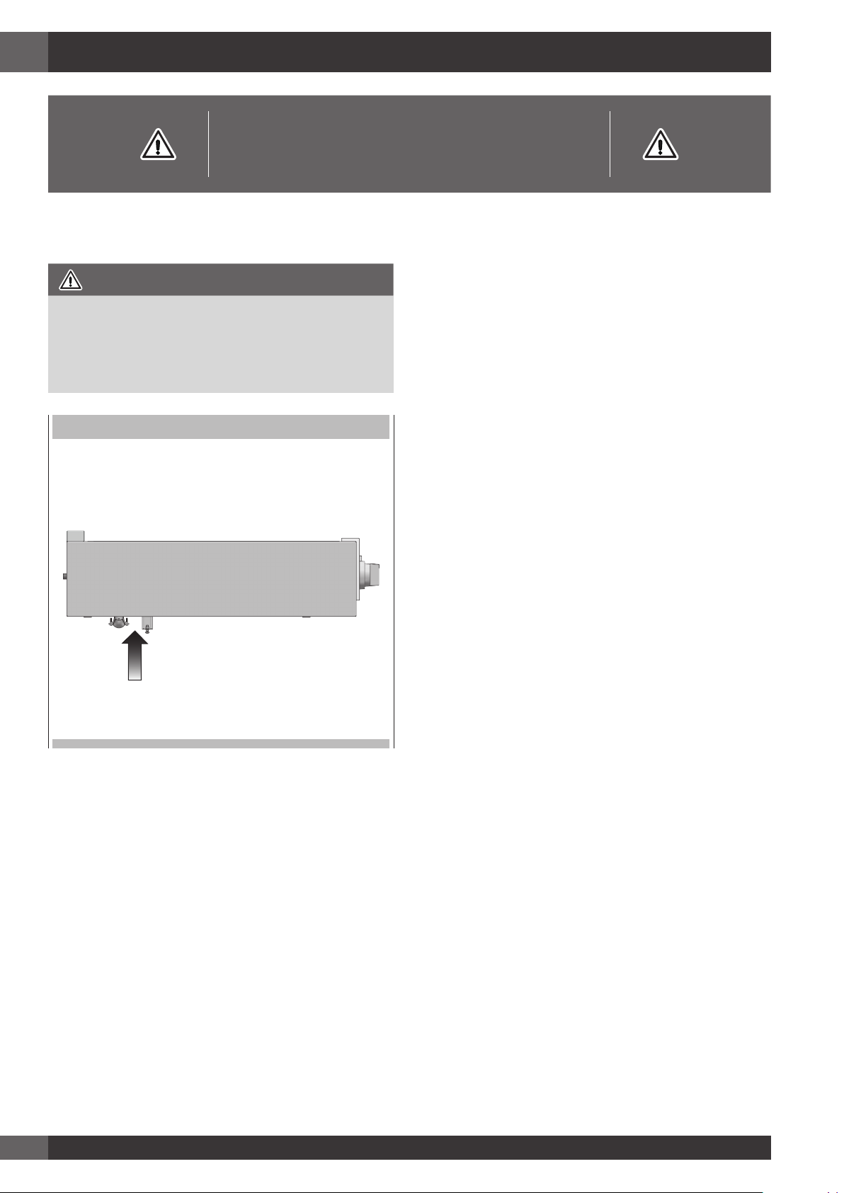
IMPORTANT
- Observe all governing codes and ordinances.
- Write down the model and serial numbers before installing
the range. Both numbers are on the serial rating plate refer
to the illustration below.
LOCATION OF RATING PLATE
Mobile Home Installation
The installation of this appliances must conform to the
Manufactured Home Construction and Safety Standards, Title
24 CFR, Part 3280 (formerly the Federal Standard for Mobile
Home Construction and Safety; Title 24 HUD part 280); or
when such standard is not applicable, the Standard for
Manufactured Home Installations (Manufactured Home Sites,
Communities and Setups), ANSI A225.1 - latest edition, or
with local codes.
In Canada, the installation of this appliances must conform
with the current standards CAN/CSA-Z240 - latest edition, or
with local codes.
Before Starting Installation
• Electrical grounding is required.
See “Electrical Requirements”
• Assure that electrical installation is adequate and in
conformance with National Electrical Code, ANSI/
NFPA 70 - latest edition**, or Canadian Electrical Code,
part 1 C22.1 (latest edition)*** and all local codes and
ordinances.
Copies of the standards listed may be obtained from:
** National Fire Protection Association One Batterymarch Park
Quincy, Massachusetts 02269
*** CSA International 8501 East Pleasant Valley Rd. Cleveland,
OH 44131-5575
2
Page 7
7” (17,9)
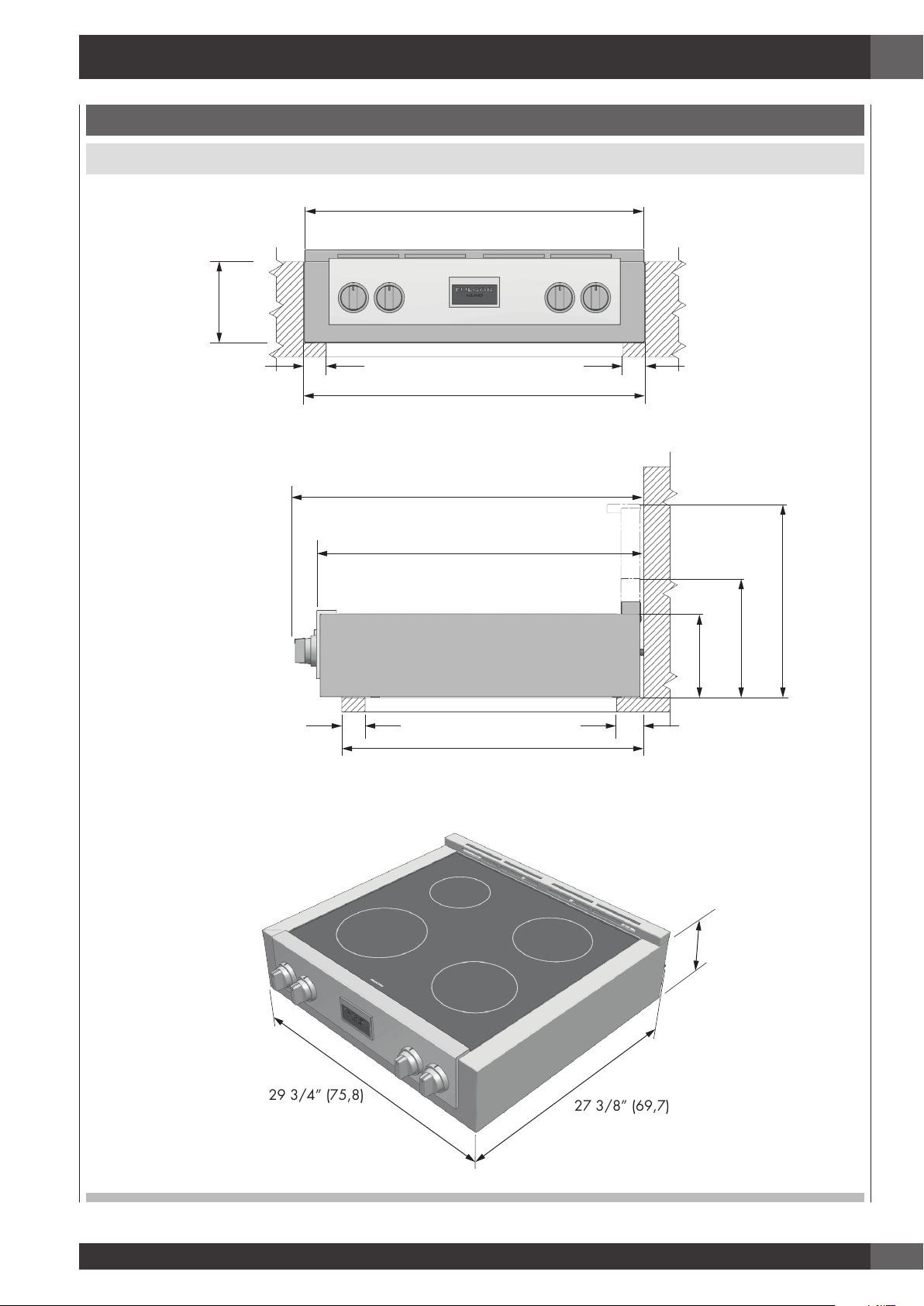
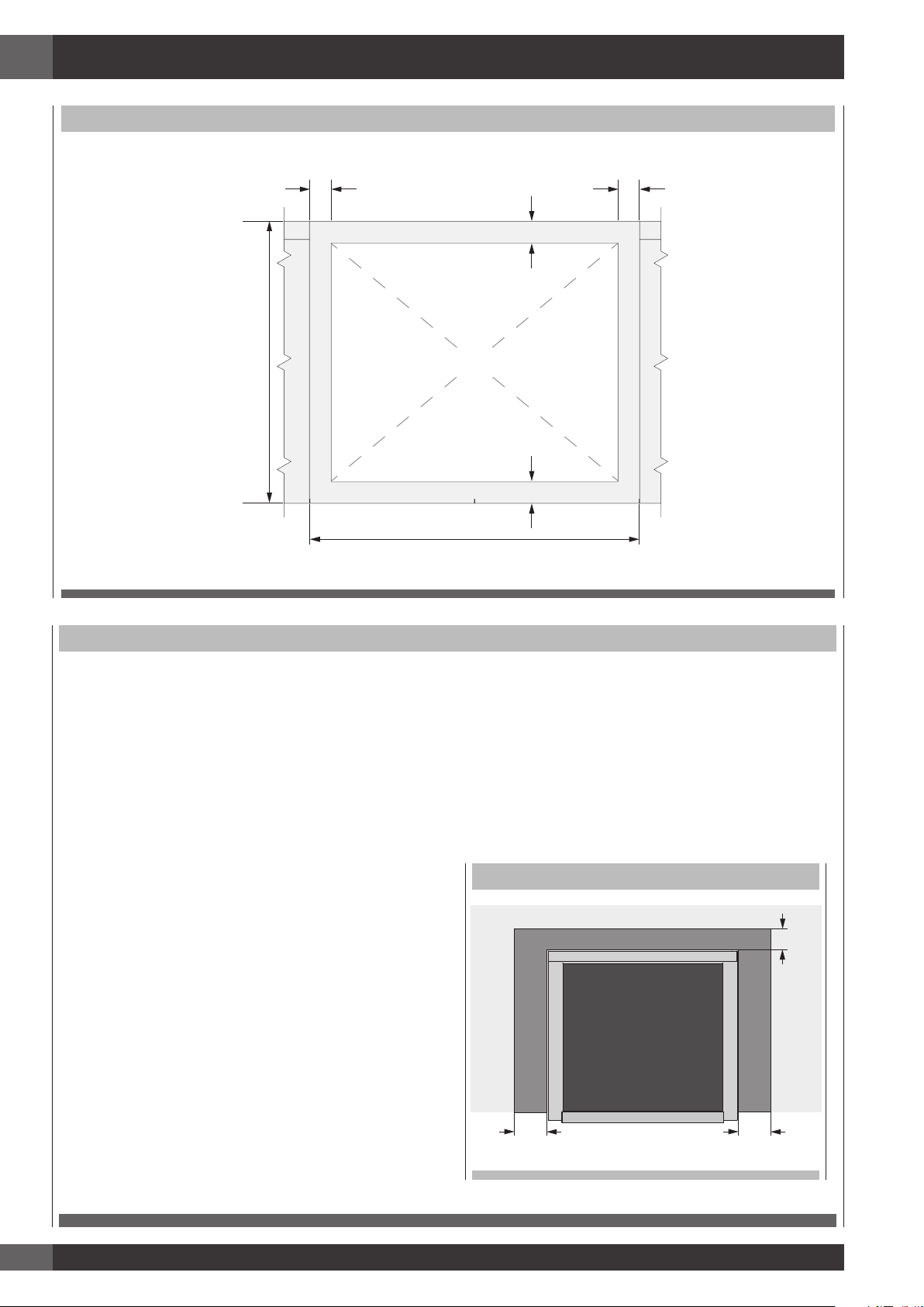
2 - Product Dimensions and Cutout Requirements
PRODUCT DIMENSIONS
30” Wide Rangetop Models
29 3/4” (75,8)
EN
2” (5)
2” (5)
30” (76,2)
29 1/2” (75,1)
27 3/8” (69,7)
min. 24” (61)
max. 25 5/8” (65)
2” (5)
7” (17,9)
2” (5)
10” (25,5)
16 3/8” (41,5)
29 3/4” (75,8)
7” (17,9)
27 3/8” (69,7)
3
Page 8
EN
(61)
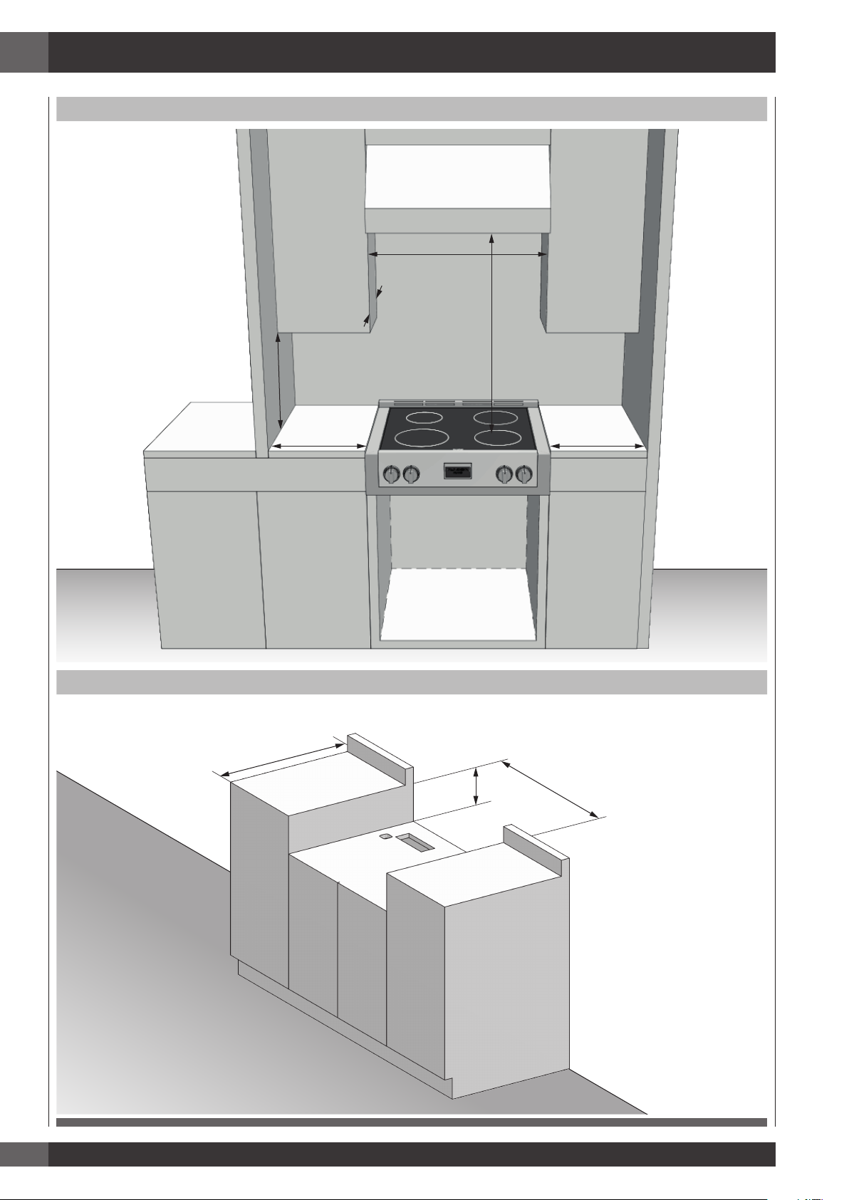
2 - Product Dimensions and Cutout Requirements
CUTOUT REQUIREMENTS
30” (76,2)
max 13” (33)
min 30” (76,2)
min 18” (45,7)
min 6” (15,2) min 6” (15,2)
to bottom of
ventilation hood
INSTALLATION WITH SEPARATOR SHEET
min 24”
max 25 1/2” (65)
Electrical
connection
in this area
9
7,
1
(
”
7
30” (76,2)
)
4
Page 9
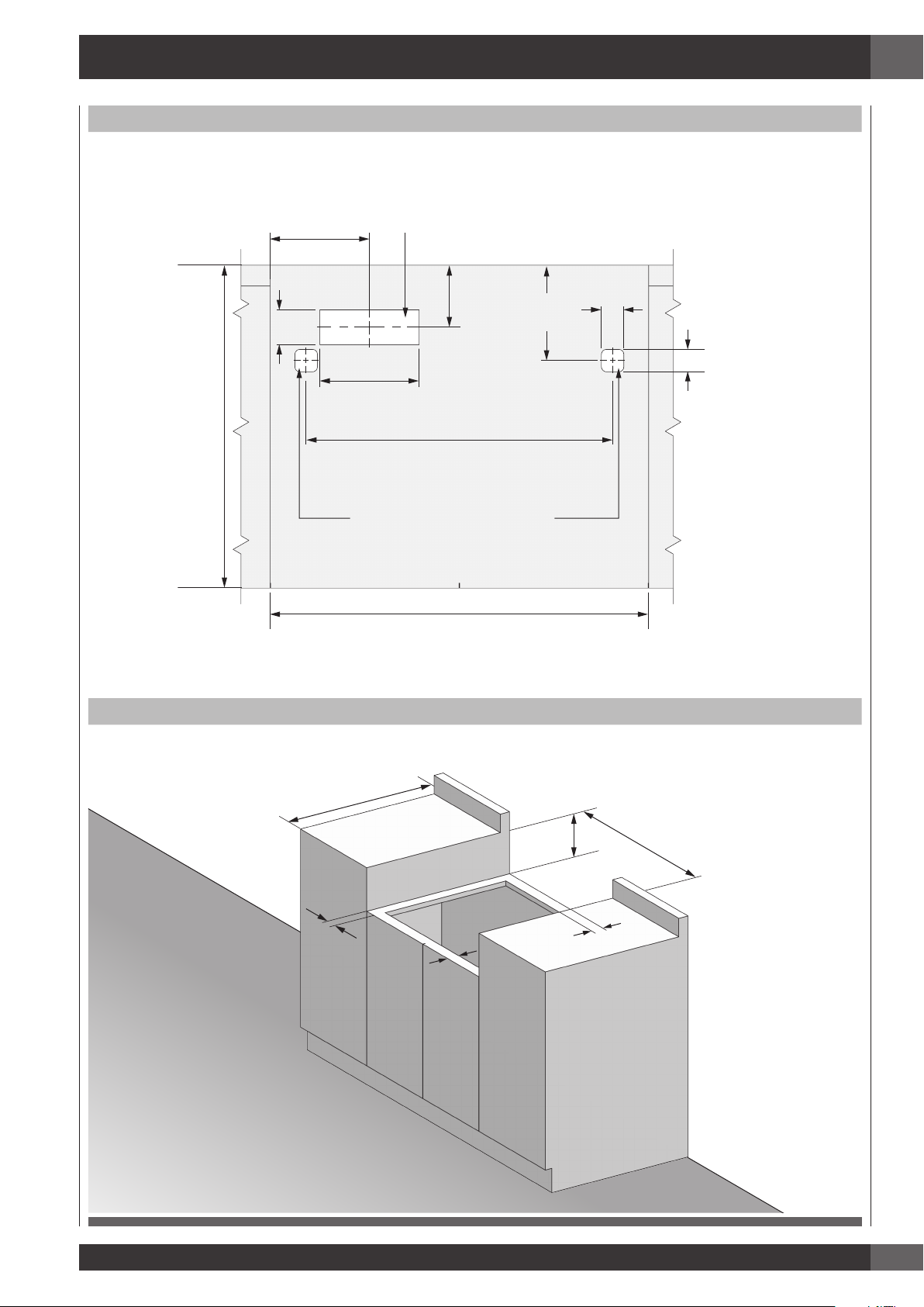
2 - Product Dimensions and Cutout Requirements
7 7/8” (20)
1 3/4” (4,5)
CUTOUT FOR ELECTRICAL
(61)
INSTALLATION WITH SEPARATOR SHEET
EN
2 3/4” (7)
min 24” (61)
max 25 1/2” (65)
4 7/8”
(12,5)
7 7/8” (20)
24 1/4” (61,7)
CUTOUT FOR FIXING BRAKETS
30” (76,2)
7 1/2”
(19,2)
1 3/4”
INSTALLATION WITHOUT SEPARATOR SHEET
(4,5)
min 24”
max 25 1/2” (65)
2
”
(
5
)
2” (5)
17,9)
(
7”
30” (76,2)
)
5
(
”
2
5
Page 10
EN
2” (5) 2” (5)
30” (76,2)
max 25 1/2” (65)
2 - Product Dimensions and Cutout Requirements
INSTALLATION WITHOUT SEPARATOR SHEET
2” (5)
EMPTY SPACE
min 24” (61)
2” (5)
CUTOUT REQUIREMENTS
The surface of the entire back wall above the range and below the hood must be covered with a noncombustible material.
*Consult local code for exact location requirements.
Note: Clearances to non-combustible materials must
conform with local codes or, in the absence of local
codes, with the National Fuel Gas Code, ANSI
Z223.1/NFPA 54.
Minimum clearances:
Above cooking surface (above 36” [91.4 cm])
• Sides 3” (7.6 cm)
ADDITIONAL CLEARANCES:
For island installation, maintain 2-½ in. minimum from
cutout to back edge of countertop and 3 in. minimum from
cutout to side edges of countertop (see top view).
FLUSH ISLAND TRIM INSTALLATION
BACK
• Within 3” (7.6 cm) side clearance, wall cabinets no
deeper than 13” (33.0 cm) must be minimum 18” (45.7
cm) above cooking surface.
• Wall cabinets directly above product must be a minimum
of 30” (76.2 cm) above cooking surface.
• Rear - 0” with 3” (7.6 cm) backguard.
min 2 1/2” (6.3)
6
min 3” (7.6) min 3” (7.6)
Page 11

2 - Product Dimensions and Cutout Requirements
Vent hood Combinations:
It is recommended that these rangetop be installed in
conjunction with a suitable overhead vent hood.
Install a hood with at least 450 CFM.
Due to the high heat capacity of this unit, particular attention
should be paid to the hood and ductwork installation to assure
it meets local building codes.
WARNING
Clearances to horizontal surfaces above the rangetop,
measured to the cooking surface are below. Failure to
comply may result in fire hazard.
• Installations without a hood require 30” (76 cm) minimum
to combustibles.
• A custom hood installation with exposed horizontal
combustible surfaces must have an Auto-On feature.
• For other installations with a hood, refer to the hood
installation instructions for specific hood clearances.
EN
CAUTION
Due to the weight and size of the range and to reduce the
risk of personal injury or damage to the product:
TWO PEOPLE ARE REQUIRED FOR PROPER INSTALLATION.
7
Page 12

EN
3 - Installation Information
WARNING
• Excessive Weight Hazard
Use two or more people to move and install rangetop.
Failure to do so can result in back or other injury.
• Cut Hazard
Beware of sharp edges. Use the polystyrene ends when
carrying the product. Failure to use caution could result in
minor injury or cuts.
DO NOT obstruct the flow of combustion and ventilation air.
All openings in the wall behind the appliance and in the
floor under the appliance must be sealed.
CHOOSING RANGE LOCATION
Carefully select the location where the rangetop will be placed.
The rangetop should be located for convenient use in the
kitchen, but away from strong drafts.
Strong drafts may be caused by open doors or windows, or by
heating and/or air conditioning vents or fans.
TOOLS WILL YOU NEED
IMPORTANT NOTE
When installing against a combustible surface, a minimum
riser is required for a the rangetop, Follow all minimum
clearances to combustible surfaces shown in the illustration
on the previous pages.
To eliminate the risk of burns or fire by reaching over heated
surface units, cabinet storage space located above the surface
units should be avoided.
If cabinet storage is to be provided, the risk can be reduced by
installing a range hood that projects horizontally a minimum of
inches beyond the bottom of the cabinets.
Remove packaging materials and literature package from the
cooktop before beginning installation.
Remove Installation Instructions from the literature pack and
read them carefully before you begin
MATERIALS PROVIDED
8
Page 13
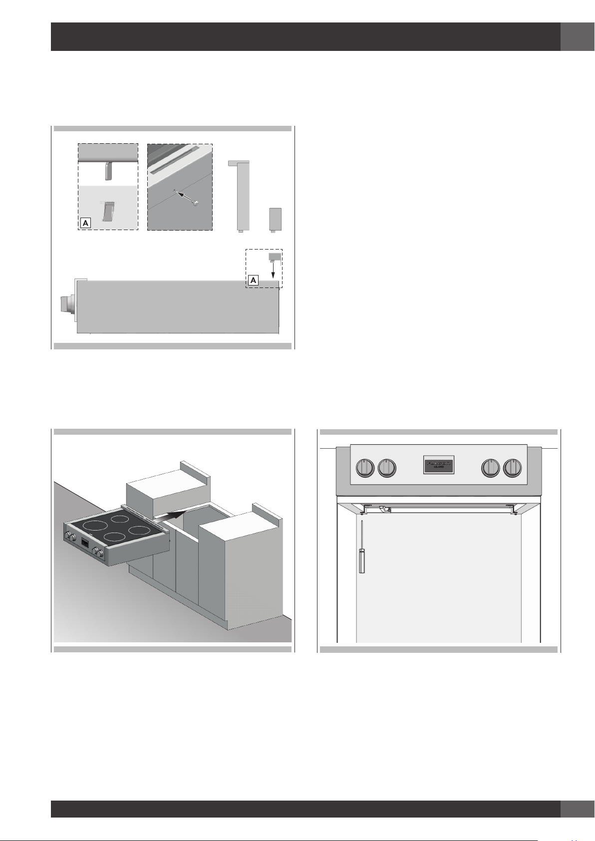
4 - Installation Instructions
EN
STEP 1
Install the backsplash (if provided) by the three screws on the
back and the toe kick
3”9”
STEP 3
Two clamp brackets are provided with your unit.
After rangetop has been installed into the countertop, install the
brackets on the burner box as shown.
step A place the clamping screws into brackets.
step B attach brackets by using the attachment screws on the
selected location of burner box, tighten screws just
enough to hold brackets in place.
step C position brackets so that they are with the clamp screw
in contact with the counter top bottom.
step D tighten attachment screws securely.
step E check that the front edge of the rangetop is parallel
to the front edge of the countertop tighten the screw
clamping against the countertop.
DO NOT OVER TIGHTEN
STEP 2
Slide the range top into place.
9
Page 14
EN
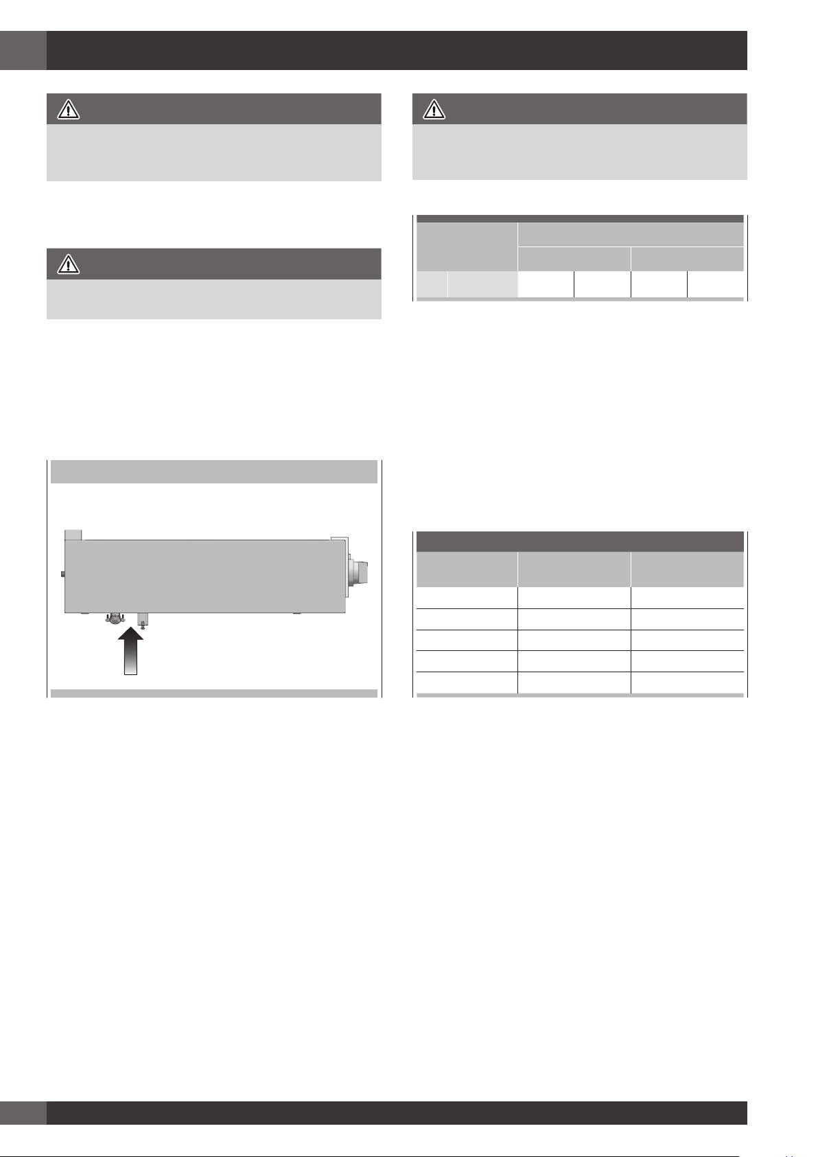
5 - Electrical Connections
DANGER
Disconnect power before servicing the product.
Failure to do so could result in death or electrical shock.
General information
WARNING
The models may be powered at 240V or 208V.
This rangetop does not require a neutral connection. If the
rangetop is to be completely enclosed in a cabinet, feed the
cooktop cable through the opening in the cabinet. Make the
electrical connection following the appropriate steps for your
installation.
Your rangetop must be connected to the proper electrical
voltage and frequency as specified in the table on the right.
LOCATION OF SERIAL TAG
WARNING
Improper connection of aluminum house wiring to the copper
leads can result in a serious problem.
Model
30“ F7IT30*1
240 V 60 Hz 208 V 60 Hz
7.20 kW 30 A 6.45 kW 31 A
National Fire Protection Association Batter/march Park
Quincy, Massachusetts 02269
A three-wire, single phase, 240 Volt 60 cycle electrical system
(properly circuit protected to meet Local Codes of NFPA
No.70) must be provided. Unit must be properly grounded
in accordance with local wiring code. The chart below
recommends the minimum circuit protector and wire size if the
appliance is the only unit on the circuit. If smaller sizes of wire
are used, the unit efficiency will be reduced and a fire hazard
may be created. It is advisable that the electrical wiring and
hookup be accomplished by a competent electrician.
Power Supply
Connect with copper wire only
If the house has aluminum wiring, follow the procedure below:
1. Connect the aluminum wiring to the copper wire by using
special connectors designed and Underwriters Laboratorieslisted for joining copper to aluminum. Follow the electrical
connector manufacturer’s recommended procedure.
2. Aluminum/copper connection must conform with local
codes and industry- accepted wiring practices.
The flexible conduit (supplied) 3 feet long (100 cm) located at
the right rear of the cooktop bottom box should be connected
directly to junction box. Do not cut the conduit. A U.L - or CSA
- listed conduit connector must be provided at each end of the
power supply cable (at the cooktop and at the junction box.) A
time delay fuse or circuit breaker is recommended.
Do not ground to a gas pipe. Do not have a fuse in the
grounding or neutral circuit.
Fuse both supply (phase) lines.
Recommended Minimum
kW Rating on
serial plate
0.1 - 4.8 20 12
4.9 - 6.9 30 10
7.0 - 9.9 40 8
10.0 - 11.9 50 8
12.0 - 14.9 60 6
Be sure your appliance is properly installed and grounded by a
qualified technician.
Ask your dealer to recommend a qualified technician or an
authorized repair service.
This rangetop does not require a neutral connection.
If the cooktop Is to be completely enclosed In a cabinet, feed the
cooktop cable through the opening in the cabinet.
Make the electrical connection following the appropriate steps
for your installation.
This appliance is manufactured with a green ground wire
connected to the cooktop chassis.
After making sure that the power has been turned off, connect
the flexible conduit from the appliance to the junction box
using a U.L. listed conduit connector.
The instructions provided below present the most common way
of connecting the cooktops.
Your local codes and ordinances, of course, take precedence
over these instructions. Complete electrical connections
according to local codes and ordinances
Circuit protection
in amperes
Wire size
(AWG)
10
Page 15

5 - Electrical Connections
DANGER
Risk of Electric Shock, frame grounded to neutral of appliance through a link.
Grounding through the neutral conductor is prohibited for new branch-circuit installations (1996 NEC); mobile homes; and
recreational vehicles, or in an area where local codes prohibit grounding through the neutral conductor.
EN
3-Wire branch circuit
Where local codes allow the connection of ground wire from
the cooktop to the branch circuit neutral wire (gray or white
colored wire) proceed as follows:
1. If local codes permit, connect the green GROUND wire
from the cooktop to the branch circuit neutral wire (gray or
white colored wire).
2. Connect the red and black leads from the cooktop to the
corresponding leads in the junction box.
Cable from power supply
Red Wires
Junction box
Twist-on connector
4-Wire branch circuit
1. Connect the green ground wire from the cooktop to the
ground wire in the junction box (bare or green colored
wire).
2. Connect the red and black leads from the cooktop to the
corresponding leads in the junction box.
3. Terminate and insulate the neutral (gray or white colored
wire) in the junction box.
Cable from power supply
Red wires
Junction box
White wire
White Wires
Bare or green wires
3-Wire cable from cooktop
U.L.-or CSA-listed conduit connector
Where local codes permit connecting the frame-ground
conductor to the neutral (white) junction box wire.
(Not used for Canadian installations)
Black wires
Bare or green wires
3-Wire cable from cooktop
U.L. - or CSA-listed conduit connector
Twist-on
connector
Black wires
11
Page 16

EN
6- Final checklist
To prevent improper connections leading to damage of
electrical components and so voiding the warranty, the
following steps must be performed:
1. Check the electrical requirements and make sure you have
the correct electrical supply and that the range is properly
grounded.
2. Before the range is connected, turn on the power supply.
3. Check power at the junction box wires using a voltmeter
having a range of 0-250 VAC.
IMPORTANT
Leave these INSTALLATION instructions as well as the USE
AND CARE MANUAL with the owner.
12
Page 17

Veuillez prêter attention à ces symboles que vous rencontrerez
dans ce manuel :
FR
TABLES DES MATIERES PAG E
1 - Avertissement Spéciaux 2
Avant de Procéder à l’Installation 2
Installation autocaravane 2
2 - Dimensions et Dispositions pour la Découpe 3
3 - Consignes d’installation 8
4 - Instructions d’Installation 9
5 - Connexions Electriques 10
Informations générales 10
Connexion à 3 fils 11
Connexion à 4 fils 11
6 - Liste de vérification finale 12
DANGER
Si vous ne suivez pas IMMEDIATEMENT ces instructions,
vous courez le risque de mourir ou d’être sérieusement
blessé.
AVERTISSEMENT
Ce symbole signifie que la sécurité est en danger. Il signale
les risques potentiels qui peuvent entraîner la mort ou des
blessures à l’opérateur ou aux autres.
Si vous ne suivez pas ces instructions à la lettre, vous courez
le risque de mourir ou d’être sérieusement blessé.
BIEN LIRE CES INSTRUCTIONS ET LES CONSERVER.
À l’installateur :
Laissez ces instructions avec l’appareil.
Au client :
Gardez ces instructions comme référence future.
IMPORTANT: Gardez ces instructions pour une utilization
d’inspection électrique locale
INSTALLATEUR: Veuillez laisser ce manuel au propriétaire
pour de futures références.
PROPRIETAIRE: Veuillez garder ce manuel pour de futures
références.
AVERTISSEMENT
Le respect minutieux des indications fournies dans ce manuel
est indispensable pour éviter le risque de feu ou d’explosion
susceptible d’endommager les biens et les produits et de
provoquer des blessures, voire même la mort.
Ne pas stocker ou utiliser de l’essence ou d’autres liquides
inflammables à proximité de cet appareil ou de tout autre
appareil électroménager.
1
Page 18

FR
1 - Avertissement Spéciaux
INSTRUCTION IMPORTANT
Avertissement Spéciaux
Veuillez lire les instructions avant toute utilisation
Il est de votre responsabilité d’installer l’appareil correctement.
Confiez l’installation de cette cuisinières à un technicien qualifié.
AVERTISSEMENT
- Respecter les règlements et ordonnances en vigueur.
- Avant l’installation de la cuisinière, noter le modèle et
les numéros de série. Les deux numéros se trouvent sur
la plaque de données dans la position indiquée dans la
figure ci-dessous.
POSITION DE LA PLAQUE SIGNALÉTIQUE
Installation autocaravane
L’installation de cette table de cuisson doit être conforme
aux Normes de Construction et de Sécurité des Habitations,
titre 24 CFR, Partie 3280 (jadis la Norme Fédérale pour la
Construction et la Sécurité des Autocaravanes; titre 24HUD
partie 280); ou lorsque de telles normes ne sont pas
applicables, la Norme pour les Installations des Habitations
(Emplacements, Communautés et Structures Habitations),
ANSI 225.1 - dernière édition ou aux réglementations locales.
Au Canada, l’installation de cette table de cuisson doit être
conforme aux normes en vigueur CAN/CSA-Z240 - dernière
édition ou aux réglementations locales.
Avant de Procéder à l’Installation
• L’appareil doit nécessairement être relié à la terre.
Voir «Conditions requises électricité».
• Veuillez vous assurer que l’installation électrique est
adéquate et conforme à la Réglementation Électrique
Nationale ANSI/NFPA 70 – dernière édition** ou à la
Réglementation Électrique du Canada, C22.1 – 1982 et
C22.2 N° 01982 (ou dernière édition)*** et à tous les
règlements et ordonnances en vigueur localement.
Vous pouvez demander une copie des standards répertoriés à:
** National Fire Protection Association One Batterymarch Park
Quincy, Massachusetts 02269
*** CSA International 8501 East Pleasant Valley Rd. Cleveland,
OH 44131 – 5575
2
Page 19

7” (17,9)
2 - Dimensions et Dispositions pour la Découpe
DIMENSIONS DU PRODUIT
Modèles de cuisinière 30”
29 3/4” (75,8)
FR
2” (5)
2” (5)
30” (76,2)
29 1/2” (75,1)
27 3/8” (69,7)
min. 24” (61)
max. 25 5/8” (65)
2” (5)
7” (17,9)
2” (5)
10” (25,5)
16 3/8” (41,5)
29 3/4” (75,8)
7” (17,9)
27 3/8” (69,7)
3
Page 20

FR
(61)
2 - Dimensions et Dispositions pour la Découpe
DISPOSITIONS POUR LA DÉCOUPE
30” (76,2)
max 13” (33)
min 18” (45,7)
min 6” (15,2) min 6” (15,2)
min 30” (76,2)
de distance avec le fond
de la hotte d'aération
INSTALLATION AVEC PLAQUE DE SEPARATION
min 24”
max 25 1/2” (65)
Branchement
électrique
dans cette zone
)
9
7,
1
(
”
7
30” (76,2)
4
Page 21

(61)
2 - Dimensions et Dispositions pour la Découpe
INSTALLATION AVEC PLAQUE DE SEPARATION
FR
7 7/8” (20)
2 3/4” (7)
min 24” (61)
max 25 1/2” (65)
DECOUPE POUR BRANCHEMENT ELECTRIQUE
4 7/8”
(12,5)
7 7/8” (20)
24 1/4” (61,7)
DECOUPES POUR ETRIERS DE FIXATION
30” (76,2)
7 1/2”
(19,2)
1 3/4”
(4,5)
1 3/4” (4,5)
INSTALLATION SANS PLAQUE DE SEPARATION
min 24”
max 25 1/2” (65)
17,9)
(
2
”
(
5
)
2” (5)
7”
30” (76,2)
)
5
(
”
2
5
Page 22

FR
2 - Dimensions et Dispositions pour la Découpe
INSTALLATION SANS PLAQUE DE SEPARATION
2” (5) 2” (5)
VIDE
max 25 1/2” (65)
min 24” (61)
2” (5)
2” (5)
30” (76,2)
DISPOSITIONS POUR LA DÉCOUPE
La totalité de la surface du mur arrière ainsi que la surface se trouvant au-dessus de la table de cuisson doit être faite d’une matière ignifuge.
*Consulter les réglementations locales pour les exigences exactes de localisation.
Remarque: La distance par rapport aux matériaux non
combustible doit respecter les réglementations
locales ou, en l’absence de celles-ci, avec le
« National Fuel Gas Code », ANSI Z223.1/
NFPA 54.
Dégagements minimums d’une construction:
ESPACE SUPPLÉMENTAIRES:
Pour une installation en îlot, maintenir une distance minimum
de 6,3 cm (2 ½ po) entre le bord et le dos du comptoir et
7,6 cm (3 po) minimum sur les côtés du comptoir (voir vue
de dessus).
INSTALLATION ÉBARBER
Au-dessus de la surface de cuisson [au-dessus de 36 po (91,4 cm)]
• Côtés - 3 po (7,6 cm)
DOS
min 2 1/2” (6,3)
• Avec un dégagement latéral de 3 po (7,6 cm) ou moins,
les placards muraux ne mesurant pas plus de 13 po (33
cm) de profondeur doivent se trouver à 18 po (45,7 cm)
minimum au-dessus de la surface de cuisson.
• Les armoires murales juste au-dessus du produit doivent
se trouver à 30 po (76.2 cm) minimum au-dessus de la
surface de cuisson
• Arrière - 0 po avec dosseret de 3 po (7,6 cm).
min 3” (7,6) min 3” (7,6)
6
Page 23

2 - Dimensions et Dispositions pour la Découpe
Disposition de hotte d’extraction:
Il est recommandé d’installer nos cuisinières avec une hotte
d’extraction suspendue.
Installez une hotte disposant d’une capacité d’évacuation d’au
moins 450 CFM.
Cet appareil produisant une importante quantité de chaleur,
vous devez porter une attention toute particulière à l’installation
de la hotte et de la conduite d’aération afin de vous assurer
qu’elle répond aux normes de construction en vigueur dans
votre region.
AVERTISSEMENT
Il faut prévoir les dégagements ci-dessous par rapport
aux surfaces horizontales qui se trouvent au-dessus de la
cuisinière.
Le non-respect de cette consigne pourrait présenter un risque
d’incendie.
• Pour les installations dépourvues de hotte, prévoyez un
espace minimum de 30” (76 cm) entre l’appareil et tout
élément inflammable situé au-dessus de celui-ci.
• Il est possible d’installer une hotte spéciale à proximité
d’éléments horizontaux inflammables dans la mesure
où celle-ci dispose d’une fonction de mise en marche
automatique.
• Pour obtenir les spécifications relatives aux espaces
d’autres installations pourvues d’une hotte, veuillez vous
reporter aux instructions fournies avec celle-ci
FR
ATTENTION
Afin d’éviter tout risque de blessure ou d’endommagement
de l’appareil et compte tenu du poids et de la taille de la
cuisinière:
DEUX PERSONNES SONT NÉCESSAIRES POUR UNE
INSTALLATION ADÉQUATE DES CUISINIÈRES.
7
Page 24

FR
3 - Consignes d’installation
AVERTISSEMENT
• Risque du fait du poids excessif
Soyez à deux personnes ou plus pour porter et installer la
cuisinières. Sinon, vous risquez de vous blesser au dos ou
de subir d’autres blessures.
• Risque de coupure
Méfiez-vous des bords tranchants et des extrémités du
polystyrène lorsque vous portez le produit. Sinon, vous
risquez de vous couper ou de vous faire légèrement mal.
NE PAS obstruer le flux de combustion et l’air de ventilation.
Toutes les ouvertures dans le mur situé derrière
l’appareil et dans le sol, sous l’appareil, doivent refermées
et scellées.
CHOIX DE LA POSITION DE LA CUISINIÈRE
Choisissez attentivement l’emplacement d’installation de la
cuisinière.
La cuisinière doit être positionnée pour être utilisée dans la
cuisine, mais loin des courants d’air.
Une porte ou une fenêtre ouvertes, l’air mis en mouvement par
les ventilateurs de chauffage/climatisation peuvent causer des
courants d’air forts.
NOTE IMPORTANTE
Si vous installez la cuisinière contre une surface combustible,
veillez à prévoir un minimum de rehausse.
Respectez toutes les distances par rapport aux surfaces
combustibles qui sont indiquées dans les pages précédentes
LES OUTILS DONT VOUS AUREZ BESOIN
Avant de commencer l’installation, enlevez les matériaux
d’emballage et les manuels d’explication sur la table de
cuisson; puis retirez du manuel d’explication, les instructions
concernant l’installation et lisez-les avec attention.
MATÉRIEL FOURNI
Pour éliminer le risque de brûlure ou d’incendie à cause
d’une surchauffe de la surface des unités, évitez de placer une
armoire de rangement au-dessus de l’unité.
Si vous avez une armoire au-dessus de la cuisinière, vous
pouvez réduire le risque en installant à une certaine distance
au-dessous de la partie inférieure de l’armoire un écran de
protection qui projette horizontalement.
8
Page 25

4 - Instructions d’Installation
FR
ÉTAPE 1
Installez le dosseret (si fourni) au moyen de trois vis dans la
partie postérieure et la plinthe
3”9”
ÉTAPE 3
2 étriers de fi xation sont fournis avec l’unité.
Une fois la table de cuisson encastrée dans le plan de travail, fi
xez les étriers sur la caisse du brûleur comme indiqué.
Etape A placez les vis de fi xation dans les étriers.
Etape B attachez les étriers par des vis de fi xation aux endroits
choisis sur la boîte du brûleur, serrez les vis juste assez
pour tenir en place les étriers.
Étape C: positionnez les étriers et les vis de fi xation de sorte
qu’ils soient au contact du bas du plan de travail.
Étape D: bien serrer les vis de fi xation.
Étape E: vérifi ez que le bord antérieur de la table de cuisson
est bien parallèle au bord du plan de travail, serrez la
vis de fi xation contre le plan de travail.
BIEN SERRER MAIS PAS TROP FORT
STEP 2
Faire glisser la cuisinière à son emplacement
9
Page 26

FR
5 - Connexions Electriques
DANGER
Débranchez l’électricité avant de mettre en service le produit.
Sinon, vous risquez de vous tuer ou de vous électrocuter.
Informations générales
AVERTISSEMENT
Les modèles peuvent être actionnés à 240V ou à 208V.
Cette table de cuisson n’exige pas de branchement neutre.
Si la table de cuisson doit être complètement fermée dans un
meuble, alimentez le câble de la table de cuisson à travers
l’ouverture du meuble. Faites les branchements électriques
selon les étapes appropriées pour votre installation. Votre table
de cuisson doit être connecté au voltage électrique correct et
au fréquence spécifié à droite.
NUMÉRO DE SÉRIE
AVERTISSEMENT
Une connexion incorrecte de l’installation électrique en
aluminium au cuivre peut entraîner des problèmes graves.
Modèle
30“ F7IT30*1
National Fire Protection Association Batter/march Park
Quincy, Massachusetts 02269
Il faut avoir une prise à trois fils, courant monophasé,
système électrique de 240 volt 60 cycles (circuit protégé
correctement pour être conforme aux codes locaux de NFPA
No.70). L’appareil doit être correctement branché selon le
code de câblage local. Le tableau ci-dessous recommande le
protecteur de circuit minimum et la taille de câble minimum si
l’appareil est le seul sur le circuit. Si des tailles de câble plus
petites sont utilisées, l’efficacité de l’appareil sera réduite et un
risque d’incendie est possible. Il est conseillé que le câblage
électrique et le branchement soit mis en place par un électricien
compétent.
Alimentation électrique requise
240 V 60 Hz 208 V 60 Hz
7.20 kW 30 A 6.45 kW 31 A
Connexion uniquement avec un câble en cuivre
Si la maison est pourvue d’un câblage aluminium, suivez la
procédure suivante:
1. Raccordez le câblage aluminium au câble en cuivre
en utilisant des raccords spéciaux conçus et venant de
Underwriters Laboratories-listed pour joindre le cuivre à
l’aluminium. Suivez les instructions recommandées du
fabricant des raccords électriques.
2. La connexion aluminium/cuivre doit être conforme aux
codes locaux et industriels acceptés pour les câblages.
Le conduit flexible conduit (fourni) de 3 pieds (100 cm) situé à
l’arrière à droite sous le caisson de la table de cuisson doit être
connecté directement à la boîte de jonction. Ne coupez pas
le conduit. Un raccord de conduit U.L - ou CSA- listed doit être
posé à chaque extrémité du câble d’alimentation électrique (à
la table de cuisson et à la boîte de jonction.) Un dispositif de
surcharge ou un disjoncteur est recommandé.
Ne le branchez pas à un tuyau à gaz. Ne placez de fusible
dans le branchement ou de circuit neutre. Raccordez les deux
lignes d’alimentation (phase).
Minimum recommandé
Caractéristiques
des kW sur
plaques de série
0.1 - 4.8 20 12
4.9 - 6.9 30 10
7.0 - 9.9 40 8
10.0 - 11.9 50 8
12.0 - 14.9 60 6
Assurez-vous que votre installation est correctement installée et
branchée par un technicien qualifié.
Demandez à votre revendeur un technicien qualifié ou un service
de réparation agréé.
Cette table de cuisson n’exige pas de connexion neutre.
Si la table de cuisson doit être complètement enfermée dans
un meuble, posez le câble de la table de cuisson à travers
l’ouverture du meuble.
Faites les branchements électriques en suivant les étapes
appropriées pour votre installation.
Cet appareil est fabriqué avec un conducteur de terre vert
connecté au châssis du table de cuisson.
Après vous être assurer qu’il n’y a plus de courant, branchez le
conduit flexible depuis le table de cuisson jusqu’au boîtier de
raccordement en utilisant un connecteur de conduit U.L. listed.
Les instructions fournies présentant la manière la plus commune
de brancher un table de cuisson. Vos codes locaux et règlements
sont évidemment prioritaires sur ces instructions.
Effectuez les connexions électriques conformément aux codes
locaux et les règlements.
Protection de circuit
en ampères
Taille de câble
(AWG)
10
Page 27

Si les règlements locaux ne permettent pas de branchement de
ble neutre (blanc) de la
te de jonction (non utilisé pour les installations
5 - Connexions Electriques
DANGER
Risque d’électrocution, cadre à la masse à une position neutre d’un appareil par une liaison
Mettre à la masse par un conducteur neutre est interdit pour les nouvelles installations de circuit électrique (1996 NEC); les mobile
homes; et les véhicules de parc, ou dans les régions où les codes locaux interdisent de brancher à la masse à travers un conducteur
neutre.
FR
Connexion à 3 fils
Où les codes locaux permettent la connexion du conducteur
de terre du four au fil neutre du circuit de branchement (fil gris
ou coloré blanc):
1. Si les codes locaux le permettent, connectez le conducteur
de terre vert du table de cuisson et le fil neutre du circuit de
branchement (fil gris ou coloré blanc).
2. Connectez les broches de raccordement du table de cuisson
aux broches de raccordement correspondantes dans le
boîtier de jonction.
Cable de l’alimentation
Cables rouges
Boite de jonction
Connecteur verrouille
par rotation
Connexion à 4 fils
1. Connectez le conducteur de terre vert du table de cuisson
au conducteur de terre dans le boîtier de jonction (câble nu
ou coloré vert).
2. Connectez les broches de raccordement rouge et noir
du table de cuisson aux broches de raccordement
correspondantes dans le boîtier de raccordement.
3. Raccordez et isolez le câble neutre (gris ou blanc) à la
boîte de jonction.
Cable de l’alimentation
Cables rouges
Boite de jonction
Cable blanc
Cable blanc
Cables nus ou vert
Cable 3 fils de la table de cuisson
Connecteur de conduit UL ou CSA Listed
conducteur à la masse de châssis au câ
boî
canadiennes)
Cable noirs
Cables nus ou vert
Cable 3 fils de la table de cuisson
Connecteur de conduit UL ou CSA Listed
Connecteur
verrouille
par rotation
Cables noirs
11
Page 28

FR
6 - Liste de vérification finale
Afin d’éviter des erreurs de raccordement pouvant porter à la
détérioration des composants électriques et à la perte d’effet
de la garantie, suivre les indications suivantes :
1. Vérifier les conditions électriques requises et s’assurer que
l’alimentation électrique est correcte et que la cuisinière est
mise à la terre correctement.
2. Avant que la cuisinière ne soit branchée, branchez
l’alimentation principale.
3. Vérifier l’arrivée de courant aux câbles de la boîte de
jonction à l’aide d’un voltmètre ayant une plage de travail
de 0-250 VAC.
AVERTISSEMENT
Laissez ces instructions d’INSTALLATION et le MANUEL
D’UTILISATION ET D’ENTRETIEN au propriétaire.
12
Page 29

Preste la debida atención a los siguientes símbolosque
encontrará en el manual:
ES
TABELA DE CONTENIDO
1 - Advertencias Especiales 2
Antes de comenzar la instalación 2
Instalación en Casas Móviles 2
2 - Dimensiones del Producto y de Encastre 3
3 - Información de instalación 8
4 - Instrucciones para la Instalación 9
5 - Conexiones Eléctricas 10
Informaciones generales 10
Circuito de conexión de 3 hilos 11
Circuito de conexión de 4 hilos 11
6 - Lista de verificación final 12
PAG E
PELIGRO
Si no sigue estas instrucciones de forma INMEDIATA, puede
correr peligro de muerte o de resultar gravemente herido.
ADVERTENCIA
• Este es el símbolo de los avisos relacionados con la
seguridad: alerta sobre potenciales peligros que pueden
derivar en muerte o daños a las personas.
• Si no sigue estas instrucciones, puede correr peligro de
muerte o de resultar gravemente herido.
LEA Y CONSERVE ESTAS INSTRUCCIONES.
Instalador:
Deje las instrucciones con el electrodoméstico.
Cliente:
Conserve las instrucciones como referencia futura.
IMPORTANTE: Guarde estas instrucciones para el uso del
inspector eléctrico local.
INSTALADOR: Por favor, deje este manual a propietario para
futuras consultas.
PROPIETARIO: Por favor, conserve este manual para futuras
consultas.
ADVERTENCIA
• La inobservancia de las indicaciones recogidas en
este manual puede derivar en muerte o en daños a las
personas.
• No almacene ni utilice gasolina u otros vapores o líquidos
inflamables cerca de este ni otro electrodoméstico.
1
Page 30

ES
1 - Advertencias Especiales
INSTRUCCIONES IMPORTANTE
Por favor, lea todas las instrucciones antes de utilizar este aparato.
Efectuar una instalación adecuada es responsabilidad suya.
Asegúrese de que el electrodoméstico es instalado por un
técnico cualificado.
IMPORTANTE
- Cumpla todas las normativas y ordenanzas vigentes aplicables.
- Antes de instalar la cocina, comprobar el modelo y los
números de serie. Los dos números se encuentran en la placa
de datos en la posición indicada en la figura a continuación
POSICIÓN DE LA PLACA DE SEÑALIZACIÓN
Instalación en Casas Móviles
La instalación de esta placa de cocina debe cumplir con
el título 24 CFR, Parte 3280 de las Normas de seguridad
y construcción de viviendas prefabricadas o móviles
estadounidenses (Manufactured Home Construction and Safety
Standards, [anteriormente denominada Federal Standard for
Mobile Home Construction and Safety (Norma federal para
seguridad y construcción de casas prefabricadas), Title 24
HUD, Part 280]; o, en caso de que dicha norma no sea
aplicable, deberá seguirse la pauta marcada por la Norma
para instalaciones en casas prefabricadas estadounidense
[(Standard for Manufactured Home Installations (Manufactured
Home Sites, Communities and Setups], ANSI A225.1 (última
edición) o bien, la normativa local existente referente a casas
móviles.
En Canadá, la instalación de esta placa de cocción debe
cumplir con las normativas actuales CAN/CSA-Z240 (última
edición) o con las normativas locales.
Antes de comenzar la instalación
• Es necesario que el electrodoméstico se conecte a una toma
de tierra.
Consulte la sección “Conexión eléctrica. Requisitos”.
• Debe asegurarse de que la instalación es adecuada y
conforme con el Código eléctrico americano (National
Electrical Code), ANSI/NFPA 70 (última edición**) o con
el Código eléctrico canadiense (Canadian Electrical Code),
C 22.1 – 1982 y C22.2 Nº 01982 (o la última edición)***
y con todos los códigos y ordenanzas locales.
• Debe asegurarse de que la conexión de gas está conforme
con los códigos y ordenanzas locales.
Puede obtener copias de las normas citadas en:
** National Fire Protection Association One Batterymarch Park
Quincy, Massachusetts 02269
*** CSA International 8501 East Ple0asant Valley Rd. Cleveland,
OH 44131-5575
2
Page 31

7” (17,9)
2 - Dimensiones del Producto y de Encastre
DIMENSIONES DU PRODUCTO
Modelos de estufa de 30” de ancho
29 3/4” (75,8)
ES
2” (5)
2” (5)
30” (76,2)
29 1/2” (75,1)
27 3/8” (69,7)
min. 24” (61)
max. 25 5/8” (65)
2” (5)
7” (17,9)
2” (5)
10” (25,5)
16 3/8” (41,5)
29 3/4” (75,8)
7” (17,9)
27 3/8” (69,7)
3
Page 32

ES
(61)
2 - Dimensiones del Producto y de Encastre
DIMENSIONES DE ENCASTRE
max 13” (33)
min 18” (45,7)
min 6” (15,2) min 6” (15,2)
30” (76,2)
Mín 30" (76,2) en la
parte inferior de la
cubierta de ventilación
INSTALACIÓN CON HOJA SEPARADORA
min 24”
max 25 1/2” (65)
Conexión eléctrica
en esta zona
)
9
7,
1
(
”
7
30” (76,2)
4
Page 33

(61)
2 - Dimensiones del Producto y de Encastre
INSTALACIÓN CON HOJA SEPARADORA
ES
7 7/8” (20)
2 3/4” (7)
min 24” (61)
max 25 1/2” (65)
DECOUPE POUR BRANCHEMENT ELECTRIQUE
4 7/8”
(12,5)
7 7/8” (20)
24 1/4” (61,7)
DECOUPES POUR ETRIERS DE FIXATION
30” (76,2)
7 1/2”
(19,2)
1 3/4”
(4,5)
1 3/4” (4,5)
INSTALACIÓN SIN HOJA SEPARADORA
min 24”
max 25 1/2” (65)
2
”
(
5
)
2” (5)
7”
17,9)
(
30” (76,2)
)
5
(
”
2
5
Page 34

ES
2 - Dimensiones del Producto y de Encastre
INSTALACIÓN SIN HOJA SEPARADORA
2” (5) 2” (5)
EL ESPACIO VACÍO
max 25 1/2” (65)
min 24” (61)
2” (5)
2” (5)
30” (76,2)
DIMENSIONES DE ENCASTRE
La supercie de toda la pared trasera sobre la cocina y por debajode la capucha debe cubrirse con un material no combustible.
*Consultar las normas locales para la exigencias exactas de colocación.
Nota: La distancia con relación a los materiales no
combustibles debe respetar las normas locales o, en
ausencia de las mismas, el « National Fuel Gas Code
», ANSI Z223.1/NFPA 54.
ESPACIOS ADICIONALES:
Para la instalación de la isla, deje un espacio mínimo de
2-½” entre la abertura y el extremo trasero de la mesada y
un mínimo de 3” entre la abertura y los extremos laterales de
la mesada (ver la vista superior).
Distancia mínima a construcciones:
INSTALACIÓN AL RAS DEL CANTO DE LA ISLA
Por arriba de la supercie de cocinar (más de 36” [91.4 cm])
• Lados - 3” (7.6 cm).
PARTE POSTERIOR
• Dentro del espacio lateral de 3” (7.6 cm), los gabinetes
de la pared no más profundos de 13” (33.0 cm) deben
estar a un mínimo de 18” (45.7 cm) por arriba de la
supercie de cocinar.
• Los gabinetes de la pared que estén directamente por
encima del producto deben estar a un mínimo de 30”
(76.2 cm) por arriba de la supercie de cocinar.
• Parte posterior - 0” a la pared posterior de 3” (7.6 cm).
min 2 1/2” (6,3)
min 3” (7,6) min 3” (7,6)
6
Page 35

2 - Dimensiones del Producto y de Encastre
Combinaciones de capuchas de ventilación:
Se recomienda que estas estufa se instalen en conjunto con
una adecuada capucha de ventilación aérea.
Instale una capucha de por lo menos 450 CFM (pies cúbicos
por minuto).
Debido a la elevada capacidad de calor de esta unidad, debe
prestarse especial atención a la instalación de la capucha y
de la red de conductos para garantizar que cumpla con los
códigos de construcción locales.
ADVERTENCIA
Distancias respecto de superficies horizontales sobre la
estufa, medidas en relación a la superficie de cocción.
No cumplir con esto puedo provocar un peligro de incendio.
• Las instalaciones sin capucha requieren un mínimo de 30”
(76 cm) respecto de elementos combustibles.
• Una instalación de capucha a medida con superficies
expuestas horizontales combustibles debe contar con una
función de encendido automático.
ES
• Para otras instalaciones con una capucha, consulte las
instrucciones de instalación de capuchas sobre espacios
específicos para capuchas.
PRECAUCIÓN
Debido al peso y tamaño de la cocina y para reducir el
riesgo de lesiones personales o daños al producto:
SE REQUIEREN DOS PERSONAS PARA UNA
INSTALACIÓN.
7
Page 36

ES
3 - Información de instalación
ADVERTENCIA
• Peligro por peso excesivo
Dos personas o más tienen que desplazar e instalar la
estufa.
De lo contrario podrían sufrir daños en la espalda u otros.
• Peligro de corte
Cuidado con las aristas cortantes. Al desplazar el
producto, agarrarlo por los protectores de poliestireno.
De lo contrario podrían sufrir heridas leves o cortes.
NO obstruya el flujo de aire de combustión y de ventilación.
Todas las aberturas en la pared detrás del aparato y en el
piso bajo el aparato deben estar selladas.
ELECCIÓN DE LA POSICIÓN DE LA COCINA
Elija con atención la posición de la estufa.
La estufa se debe colocar en una posición que permita una
utilización práctica, pero alejada de corrientes de aire fuertes.
Una puerta o una ventana abiertas, el aire en movimiento por
ventiladores de calefacción/refrigeración pueden originar
fuertes corrientes de aire.
No taponar los flujos de aire en combustión a nivel de la
apertura de ventilación del horno ni debajo de panel frontal
inferior de la cocina. Evitar tocar las aperturas de ventilación
o las superficies cercanas ya que estas superficies podrían
calentarse mientras que el horno está funcionando.
Es indispensable que haya un aire fresco para una buena
combustión en el quemador.
HERRAMIENTAS NECESARIAS
Retire el embalaje y separe los manuales de instrucciones
antes de comenzar la instalación.
Lea atentamente los manuales de instalación antes de
comenzar.
NOTA IMPORTANTE
Si instala la estufa contra una superficie combustible,
prevea un mínimo de realce Respete todas las distancias
con relación a las superficies combustibles indicadas en las
páginas anteriores.
Si tiene un armario encima de la cocina, puede reducir el
riesgo instalando a una cierta distancia por debajo de la parte
inferior del armario una pantalla de protección que recubra
toda la superficie horizontal
MATERIALES PROVISTOS
8
Page 37

4 - Instrucciones para la Instalación
ES
PASO 1
Instalar la parte dorsal (si se entrega) por medio de tres tornillos
en la parte trasera y el pinto.
3”9”
PASO 3
En el embalaje del producto han sido incluidas cuatro grapas
de fi jación. Una vez haya instalado la placa de cocción en la
encimera, instale las grapas en la placa tal y como se indica
en la fi gura.
paso A coloque los tornillos de fi jación en las grapas.
paso B una vez haya colocado los tornillos en los puntos
indicados de la carcasa de los quemadores, ajústelos.
Apriete los tornillos lo sufi ciente para mantener las
grapas fi jadas.
paso C coloque las grapas de forma que estén encontacto
con la base de la encimera.
paso D apriete los tornillos de fi jación hasta que estén bien
asegurados.
paso E compruebe que el borde delantero de la placa de
cocción esté paralelo al borde delantero de la
encimera y apriete el tornillo de fi jación contra la
encimera.
NO APRIETE DEMASIADO LOS TORNILLOS
PASO 2
Deslice la cubierta superior en su lugar.
9
Page 38

ES
5 - Conexiones Eléctricas
PELIGRO
Desconecte la electricidad antes de instalar el producto. Si
no lo hace, podría correr peligro de muerte o de sufrir una
descarga eléctrica.
Informaciones generales
ADVERTENCIA
Los modelos se pueden accionar en 240V o 208V.
Esta placa de cocción no requiere conexión del neutro. Si va
a colocar la placa en un armario, asegúrese de que en él hay
una abertura para pasar el cable de alimentación. Efectúe
la conexión eléctrica siguiendo los pasos adecuados para su
instalación.
La placa debe estar conectada al voltaje y la frecuencia
adecuados, tal y como se indica a la derecha.
LOCACION NUMERO DI SERIE
ADVERTENCIA
Una conexión inadecuada del cableado de aluminio al
cableado de cobre puede provocar graves problemas.
Modelo
30“ F7IT30*1
240 V 60 Hz 208 V 60 Hz
7.20 kW 30 A 6.45 kW 31 A
National Fire Protection Association Batter/march Park
Quincy, Massachusetts 02269
Debe instalarse un sistema eléctrico de tres cables, una fase,
240 voltios y 60 ciclos, debidamente protegido conforme al
código local de la NFPA n.º 70. La unidad debe conectarse
adecuadamente a una toma de tierra de acuerdo con los
códigos locales. La tabla que encontrará a continuación
recoge las recomendaciones mínimas de protección del
circuito y el calibre del cableado si el electrodoméstico es la
única unidad del circuito. Si utiliza un calibre de cableado
menor, la eficiencia de la unidad se vería reducida y podría
provocar un riesgo de incendio.
Es recomendable que la conexión del cableado y del
electrodoméstico sean efectuadas por un electricista
cualificado.
Alimentación
Utilice únicamente cableado de cobre
Si su vivienda tiene cableado de aluminio, siga este
procedimiento:
1. Conecte el cable de aluminio al cable de cobre utilizando
los conectores específicos diseñados y garantizados por
Underwriters Laboratories (UL) para conectar cobre y
aluminio. Siga el procedimiento recomendado por el
fabricante del conector eléctrico.
2. La conexión aluminio-cobre debe estar conforme con los
códigos locales y con las prácticas industriales aprobadas.
El conducto flexible (suministrado con el producto) de 100 cm
de longitud que se encuentra en la parte trasera derecha de la
caja de la placa, debe conectarse directamente a la caja de
empalme. No corte el conducto.
Debe conectar un conector aprobado por UL o CSA en cada
extremo del cable de alimentación (en la placa y la caja de
empalme). Es recomendable instalar también un fusible de
acción retardada o un diferencial.
No utilice como toma de tierra una tubería de gas. No conecte
la toma de tierra o el circuito neutro cerca de un fusible. Instale
fusibles en las dos líneas (fases) de alimentación.
Mínimos recomendados
Potencia (kW)
placa de serie
0.1 - 4.8 20 12
4.9 - 6.9 30 10
7.0 - 9.9 40 8
10.0 - 11.9 50 8
12.0 - 14.9 60 6
Asegúrese de que un técnico cualificado instale y conecte a tierra
correctamente su aparato.
Consulte con su vendedor para que le recomiende un técnico
cualificado o un servicio de mantenimiento autorizado. Esta
placa de cocción no requiere
conexión del neutro.
Si va a colocar la placa en un armario, asegúrese de que en él
hay una abertura para pasar el cable de alimentación.
Efectúe la conexión eléctrica siguiendo los pasos adecuados
para su instalación.
Este aparato está fabricado con un hilo verde de tierra
conectado al bastidor de la placa de cocción.
Después de haberse asegurado de que la corriente está
desconectada, conecte el conducto flexible desde la placa de
cocción hasta la caja de empalme usando un conector de
conducto que figure en la lista U L. Las figuras 13 y 14 que
aparecen debajo muestran las maneras más comunes para
conectar la placa de cocción.
Las disposiciones y las normas locales de su zona, por su
puesto, tienen precedencia con respecto a estas instrucciones.
Complete las conexiones eléctricas en conformidad con las
normas y disposiciones locales.
Protección del
circuito en ampere
Calibre del
cable (AWG)
10
Page 39

ódigos locales no permiten la conexión del conductor
de tierra al cable neutro (blanco) de la caja de empalme (no
5 - Conexiones Eléctricas
PELIGRO
Riesgo de electrocución, marco conectado a tierra al neutro del aparato por medio de un enlace.
La puesta a tierra por medio de un conductor neutro está prohibida para las instalaciones de nuevos circuitos de conexión (1996
NEC); casas móviles, vehículos recreativos, o en áreas en donde las normas locales prohíben la conexión a tierra mediante un
conductor de neutro.
ES
Circuito de conexión de 3 hilos
Tome como referencia la figura 13, en la que las normas
locales permiten conectar el hilo de toma de tierra desde la
placa de cocción hasta el hilo de neutro del circuito (hilos de
color gris o blanco):
1. Si las normas locales lo permiten, conecte el cable cable
lo verde de tierra desde la placa de cocción y el cable
de neutro del circuito de conexión (hilos de color gris o
blanco).
2. Conecte los conductores rojo y negro desde la placa de
cocción hasta los conductores correspondientes en la caja
d empalme.
Cable desde la alimentación eléctrica
Cables rojos
Caja de empalme
Conector twist-on
Circuito de conexión de 4 hilos
1. Conecte el cable verde de tierra desde la placa de cocción
al cable de tierra en la caja de empalmes (cable de color
carne o verde).
2. Conecte los conectores rojo y negro desde el placa de
cocción hasta los conectores correspondientes en la caja
de empalme.
3. Conecte y aísle el cable neutro (gris o blanco) a la caja de
empalme.
Cable desde la alimentación eléctrica
Cables rojos
Caja de empalme
Cable blanco
Cable blanco
Cables desprotegidos
o verdes
Cableado de la placa (3 cables)
Conector aprobado por UL o CSA
Si los c
aplicable a instalaciones canadienses)
Cables negros
Cables desprotegidos
o verdes
Conector
twist-on
Cables negrosCableado de la placa (3 cables)
Conector aprobado por UL o CSA
11
Page 40

ES
6 - Lista de verificación final
Para evitar errores de empalme que pueden originar el
deterioro de los componentes eléctricos y la pérdida de efecto
de la garantía, seguir las indicaciones:
1. Comprobar los requisitos eléctricos y asegurarse de que
la alimentación eléctrica es correcta y la cocina puesta a
tierra correctamente.
2. Antes de conectar la estufa, conecte la alimentación
eléctrica.
3. Comprobar la llegada de corriente a los cables de la caja
de conexión con un voltímetro 0-250 VAC.
IMPORTANT
Dejar estas instrucciones de INSTALACIÓN y el MANUAL
DE USO Y MANTENIMIENTO al propietario.
12
Page 41

Note / Note / Nota
13
Page 42

Note / Note / Nota
14
Page 43

Page 44

09FL8530 ed 02/2018
 Loading...