

Fujitsu Technology Solutions SCENIC8651 User Manual
r
Introduction
This Operating Manual tells you how to put your PC into operation and how to operate it in daily use.
This description applies for all configuration levels. Depending on the configuration level chosen
some of the hardware components described may not be available on your PC. Please observe the
notes on your operating system.
Your device is a powerful PC which is suitable for both professional and private use.
Your PC is available in various configuration levels, which differ in hardware and software
equipment. In addition, you can incorporate operable drives (for example DAT drive, streamer) and
a second hard disk, as well as other boards.
Depending on the configuration level chosen, your PC is supplied with Windows 9x or Windows NT
as the operating system.
Your PC has a number of security features to ensure that no unauthorized persons can access your
data. For example, you can activate a screen saver with password protection. The security functions
BIOS Setup
in the
also lock your PC mechanically using the cover lock. Systems with a chipcard reader offer additional
protection.
Further information on this PC is provided:
•
in the manual "Safety, Guarantee and Ergonomics"
•
in the Operating Manual for the monitor
•
in the Technical Manual for the system board
•
in the manual "BIOS Setup"
•
in the documentation of your operating system
•
in the information files (e. g.
also allow you to protect your data by means of passwords. In addition, you can
*.TXT, *.DOC, *.WRI, *.HLP
)
Some of the manuals listed can be found on the CD "Drivers & Utilities" provided with you
computer. These manuals can be read and printed with the Acrobat Reader contained on
i
the CD.
Notational conventions
The meanings of the symbols and fonts used in this manual are as follows:
Pay particular attention to texts marked with this symbol. Failure to observe this warning
endangers your life, destroys the system, or may lead to loss of data.
!
This symbol is followed by supplementary information, remarks and tips.
i
Texts which follow this symbol describe activities that must be performed in the order shown.
Texts in this typeface
Texts in italics
"Quotation marks" indicate names of chapters and terms that are being emphasized.
A26361-K516-Z100-3-7619
indicate commands or menu items.
are screen outputs.
1

Important notes
In this chapter you will find information regarding safety which it is essential to take note of when
working with your PC. The manufacturer's notes contain helpful information on your PC.
Safety
Pay attention to the information provided in the manual "Safety, Guarantee and
Ergonomics" and to the following notes.
!
•
During installation and before operating the device, observe the instructions on environmental
conditions in the chapter entitled "Technical data
"Preparation for use and operation
•
Please check whether the device is set to the local power supply (see chapter "Preparation for
use and operation").
•
The main switch and the ON/OFF switch do not disconnect the system unit from the line
voltage. To disconnect the line voltage completely, remove the power plug from the grounded
power outlet.
•
Replace the lithium battery on the system board in accordance with the instructions in the
chapter "System expansions
•
Caution: components in the system can get very hot.
•
Keep this Operating Manual together with your device. If you pass on the device to third
parties, you should also pass on this manual.
".
- Replacing processor and lithium battery".
" as well as the instructions in the chapter
Notes on installing and removing boards
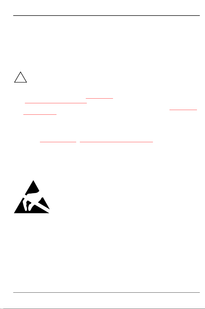
Boards with electrostatic sensitive devices (ESD) may be identified by the
label shown.
When you handle boards fitted with ESDs, you must observe the following
points under all circumstances:
•
You must always discharge yourself (e.g. by touching a grounded
object) before working.
•
The equipment and tools you use must be free of static charges.
•
Pull out the power plug before inserting or pulling out boards containing
ESDs.
•
Always hold boards with ESDs by their edges.
•
Never touch pins or conductors on boards fitted with ESDs.
A26361-K516-Z100-3-7619
3

Important notes Manufacturer's notes
Manufacturer's notes
Energy saving
When the PC is delivered, some energy-saving functions are already set (see the Technical Manual
for the system board or the manual "BIOS Setup").
•
If you are not using your PC, switch it off.
•
Energy saving under Windows NT
If the attached monitor and screen controller support power management in accordance with VESA
(DPMS), the screen saver
into power management mode.
Energy saving under Windows 95
The
following item in the
Energy saving features of monitor
Energy saving under Windows 98
In the
management functions.
Disposal and recycling
This device has been manufactured to the greatest possible degree from materials which can be
recycled or disposed of in a manner that is not environmentally damaging. The device is taken back
after use, so that it can be recycled, provided that it is returned in a condition which is the result of
normal use. Any components not recuperated will be disposed of in an environmentally acceptable
manner.
BIOS Setup
In the
Manual of the system board or in the manual "BIOS Setup").
Screen Saver
Start - Settings - Control Panel - Power Management
you may set further energy-saving functions for the PC (see the Technical
Powersaver
tab allows you to set further energy-saving functions for your screen. Select the
Start
menu:
("Drivers & Utilities" CD) can be used to switch the monitor
Settings - Control Panel - Display - Display Properties - Screen Saver -
.
menu you can set additional power-
For devices marked with this symbol Siemens AG offers a guarantee for
36 months with a Bring-in-Service. The guarantee starts on the day of
delivery (sale date) by Siemens or a Siemens partner.
We herewith declare that it will be possible to repair any device marked with
the eco-label for at least 5 years after production of that device has
discontinued.
Information on power management and energy saving mode can be found in
chapter "Technical data
Do not throw lithium batteries or accumulators into the trashcan. They must be disposed of in
accordance with local regulations concerning special waste.
4
".
A26361-K516-Z100-3-7619

Manufacturer's notes Important notes
If you have any questions on disposal, please contact your local office, our service department, or,
directly:
Siemens AG
Recyclingcenter
D-33106 Paderborn
Tel.: 49 5251 818 010
Fax: 49 5251 818 015
CE certificate
The shipped version of this device complies with the requirements of the EEC directives
89/336/EEC "Electromagnetic compatibility" and 73/23/EEC "Low voltage directive".
FCC Class B Compliance Statement
If there is an FCC statement on the device, then:
The following statement applies to the products covered in this manual, unless otherwise specified
herein. The statement for other products will appear in the accompanying documentation.
NOTE:
This equipment has been tested and found to comply with the limits for a "Class B" digital device,
pursuant to Part 15 of the FCC rules and meets all requirements of the Canadian InterferenceCausing Equipment Regulations. These limits are designed to provide reasonable protection against
harmful interference in a residential installation. This equipment generates, uses and can radiate
radio frequency energy and, if not installed and used in strict accordance with the instructions, may
cause harmful interference to radio communications. However, there is no guarantee that
interference will not occur in a particular installation. If this equipment does cause harmful
interference to radio or television reception, which can be determined by turning the equipment off
and on, the user is encouraged to try to correct the interference by one or more of the following
measures:
•
Reorient or relocate the receiving antenna.
•
Increase the separation between equipment and the receiver.
•
Connect the equipment into an outlet on a circuit different from that to which the receiver is
connected.
•
Consult the dealer or an experienced radio/TV technician for help.
Siemens AG is not responsible for any radio or television interference caused by unauthorized
modifications of this equipment or the substitution or attachment of connecting cables and
equipment other than those specified by Siemens AG. The correction of interferences caused by
such unauthorized modification, substitution or attachment will be the responsibility of the user.
The use of shielded I/O cables is required when connecting this equipment to any and all optional
peripheral or host devices. Failure to do so may violate FCC rules.
A26361-K516-Z100-3-7619
5
Important notes Manufacturer's notes
Power cord selection
The power cord for this unit has been packed
separately and has been selected according to
the country of destination. It must be used to
prevent electric shock. Use the following
guidelines if it is necessary to replace the
original cord set.
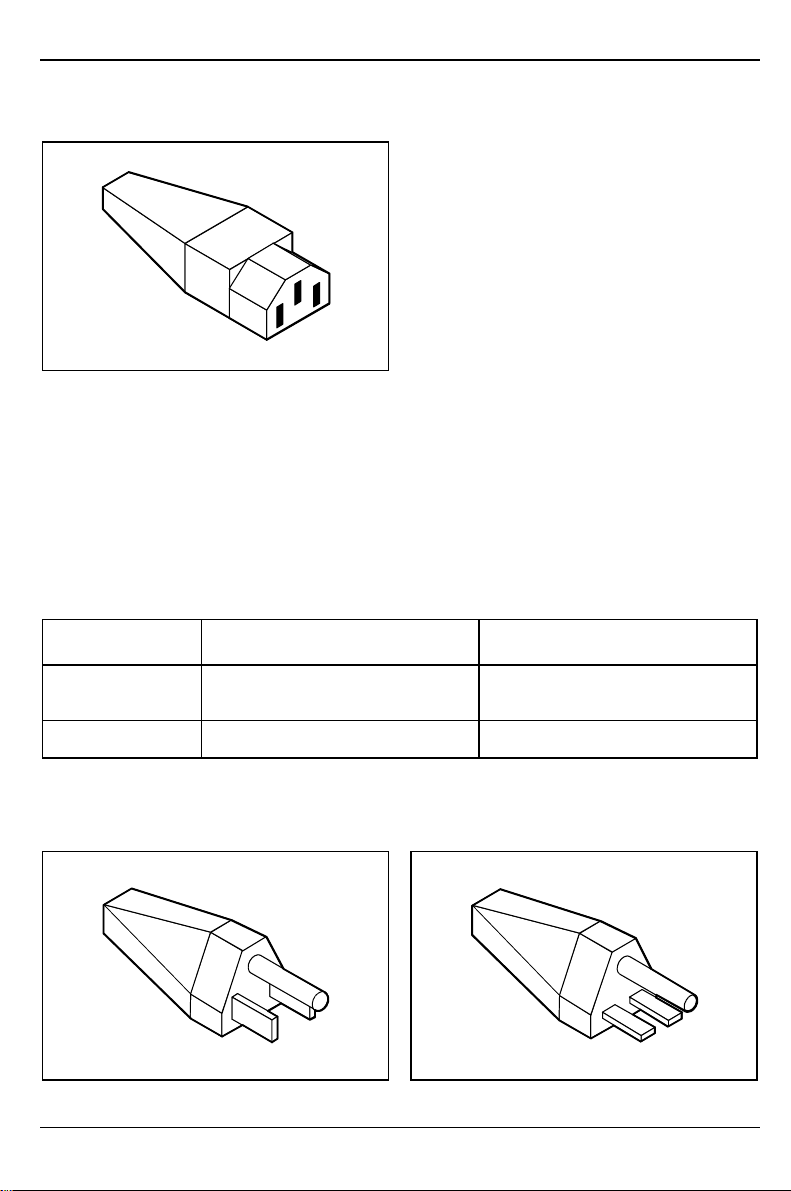
The female receptacle of the cord set must meet
CEE-22 requirements (see Figure).
For the United States and Canada
Use a UL listed and CSA labeled cord set consisting of a three conductor cord with a maximum
length of 15 feet.
For units which stand on a desk or table, type SVT or SJT cord sets shall be used.
For units which stand on floor, only SJT type cord sets shall be used.
The cord set must be selected according to the current rating for your unit. Please consult Table A
for the selection criteria for power cords used in the United States and Canada.
Table A:
Cord Type Size of Conductors
in Cord
SJT 18 AWG
16 AWG
14 AWG
SVT 18 AWG
17 AWG
Maximum Current
Rating of Unit
10 Amps
12 Amps
12 Amps
10 Amps
12 Amps
For units set at 115 V:
use a parallel blade, grounding type attachment
plug rated 15 A, 125 V.
6
For units set at 230 V (domestic use):
use a tandem blade, grounding type attachment
plug rated 15 A, 250 V.
A26361-K516-Z100-3-7619

Transporting the PC Important notes
For units set at 230 V (outside of the United States and Canada):
use a cord set consisting of a minimum AWG according to Table A and a grounding type attachment
plug rated 15 A, 250 V. The cord set should have the appropriate safety approvals for the country in
which the equipment will be installed and should be marked HAR.
For the United Kingdom
Should the plug on the flexible cord not be of the type for your socket outlets, do not use an adapter
but remove the plug from the cord and discard. Carefully prepare the end of the supply cord and fit a
suitable plug.
WARNING
THIS APPLIANCE MUST BE EARTHED
IMPORTANT
The wires in this mains lead are colored in accordance with the following code:
Green and Yellow: Earth
Blue: Neutral
Brown: Live
As the colors of the wires in the mains lead of this appliance may not correspond with the colored
markings identifying the terminals in your plug, proceed as follows:
•
The wire which is colored Green and Yellow must be connected to the terminal in the plug
which is marked with the letter E or by the earth symbol or colored Green or Green and Yellow.
•
The wire which is colored Blue must be connected to the terminal which is marked with the
letter N or colored Black.
•
The wire which is colored Brown must be connected to the terminal which is marked with the
letter L or colored Red.
Transporting the PC
Transport all parts separately, and in their original packaging or in a packaging which
protects them from knocks and jolts, to the new site. Do not unpack them until all transport
!
maneuvers are completed.
Never drop the monitor (risk of implosion)!
A26361-K516-Z100-3-7619
7
Important notes Cleaning the PC
Cleaning the PC
Turn off all power and equipment switches and pull the power plug out of the grounded
power outlets.
!
Do not clean any interior parts yourself, leave this job to a service technician.
Do not use any cleaning agents that contain abrasives or may corrode plastic.
Ensure that no liquid enters the system.
Ensure that the ventilation areas of the system unit and the monitor are free.
Cleaning the system unit and the monitor
Wipe the system unit and monitor casing with a dry cloth. If particularly dirty, use a cloth which has
been moistened in mild domestic detergent and then carefully wrung out.
Cleaning the keyboard and the mouse
Use a cloth for disinfection to clean the keyboard and the mouse.
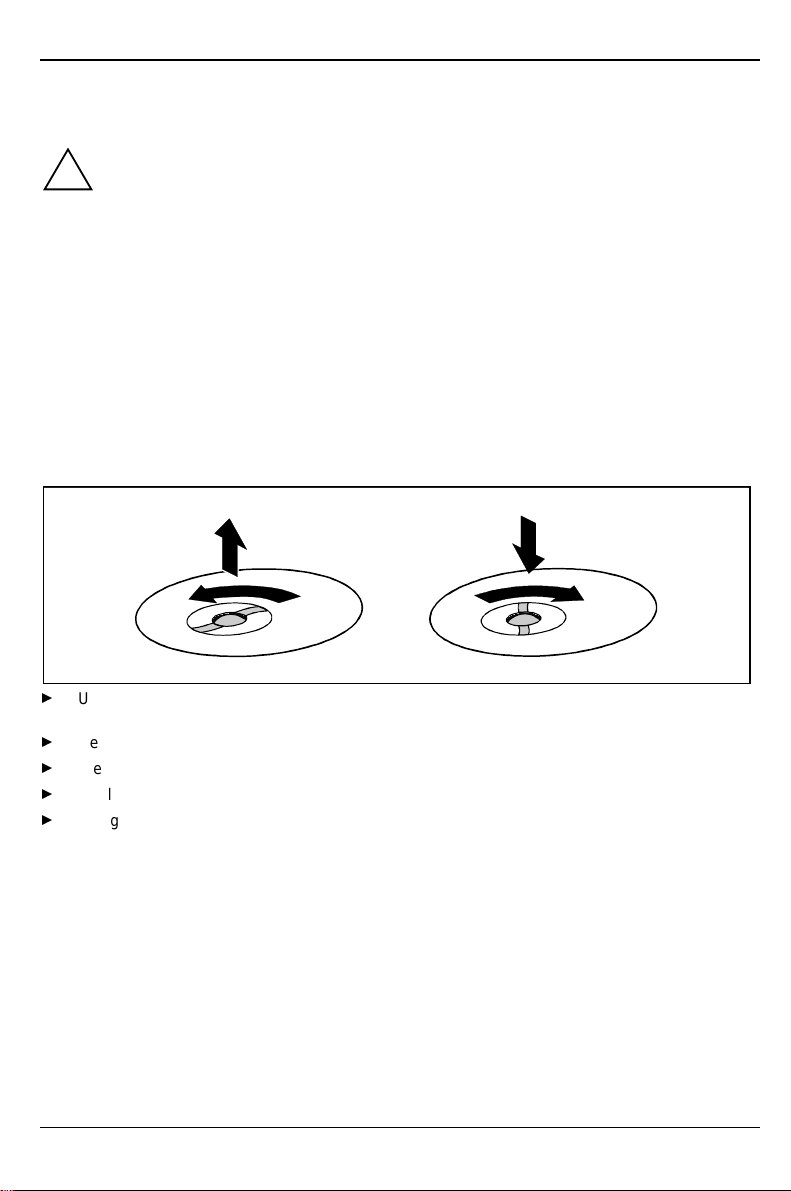
Remove the retaining ring on the underside of the mouse and then clean the mouse mechanism and
the rotating ball.
2
1
Using both thumbs exert downward pressure on the notches of the retaining ring and turn the
ring anticlockwise (1).
Remove the retaining ring and the rotating ball from the mouse (2).
Clean the three small wheels in the mouse and the ball with a lint-free cloth.
Replace the ball and the retaining ring (3).
Using both thumbs exert downward pressure on the notches of the retaining ring (4) and turn
the ring clockwise. You must feel the ring engage.
3
4
8
A26361-K516-Z100-3-7619
Preparation for use and operation
Please take note of the safety information in the chapter "Important notes".
!
Unpacking and checking the delivery
It is recommended not to throw away the original packaging material! It may be required for
reshipment at some later date.
Unpack all the individual parts.
Check the delivery for damage incurred during transport.
Check whether the delivery agrees with the details in the delivery note.
Should you discover that the delivery does not correspond to the delivery note, notify your local
sales office immediately.
If you have received drives or boards with your PC, please do not install them until after
first-time setup. How to install drives and boards is described in the chapter "System
i
expansions".
Preparing the PC for use
First-time setup includes the connection of the devices (monitor, mouse, keyboard etc.) and the
setup of the supplied software.
When you set up the PC for the first time, you should carry out the following steps in the order
shown:
1. Decide where you are going to use the PC.
2. Connect the external devices to the system unit.
3. Check the rated voltage of the system unit and connect it to the line voltage.
4. Switch the PC on and follow the instructions on the screen.
A26361-K516-Z100-3-7619
9

Preparation for use and operation Setting up the PC
Setting up the PC
When installing your PC, give consideration to the recommendations and safety notes in
the manual "Safety, Guarantee and Ergonomics".
!
Set up the PC only in its correct orientation. The points to observe are illustrated on the
following pages.
We recommend that you place your equipment on a surface with good anti-slip qualities.
In view of the multitude of different finishes and varnishes used on furniture, it is possible
that the rubber feet of the devices will mark the surface they stand on.
Do not expose the PC to extreme environmental conditions (see chapter "Technical
data"). Protect it from dust, humidity and heat.
Provide at least 200 mm of clearance on the left, in front of and behind the ventilator area
of the system unit to ensure adequate ventilation. Do not cover the ventilation areas of the
monitor and the fan.
Do not place several system units one above the other.
Connecting devices
The power plug must be disconnected!
!
Read the documentation on the external device before connecting it.
Do not connect or disconnect cables during a thunderstorm.
Always take hold of the actual plug body. Never unplug a cable by pulling the cable itself!
Connect and disconnect the cables in the order described below.
Connecting cables
•
Turn off all power and equipment switches.
•
Unplug all power plugs from the grounded power outlets.
•
Connect all cables at the system unit and peripherals. You must observe the information
provided in the chapter "Important notes".
•
Plug all data communication cables into the utility sockets.
•
Plug all power cables into the grounded power outlets.
Disconnecting cables
•
Turn off all power and equipment switches.
•
Unplug all power plugs from the grounded power outlets.
•
Unplug all data communication cables from the utility sockets.
•
Disconnect all cables from the system unit and peripherals.
10
A26361-K516-Z100-3-7619
Connecting devices Preparation for use and operation
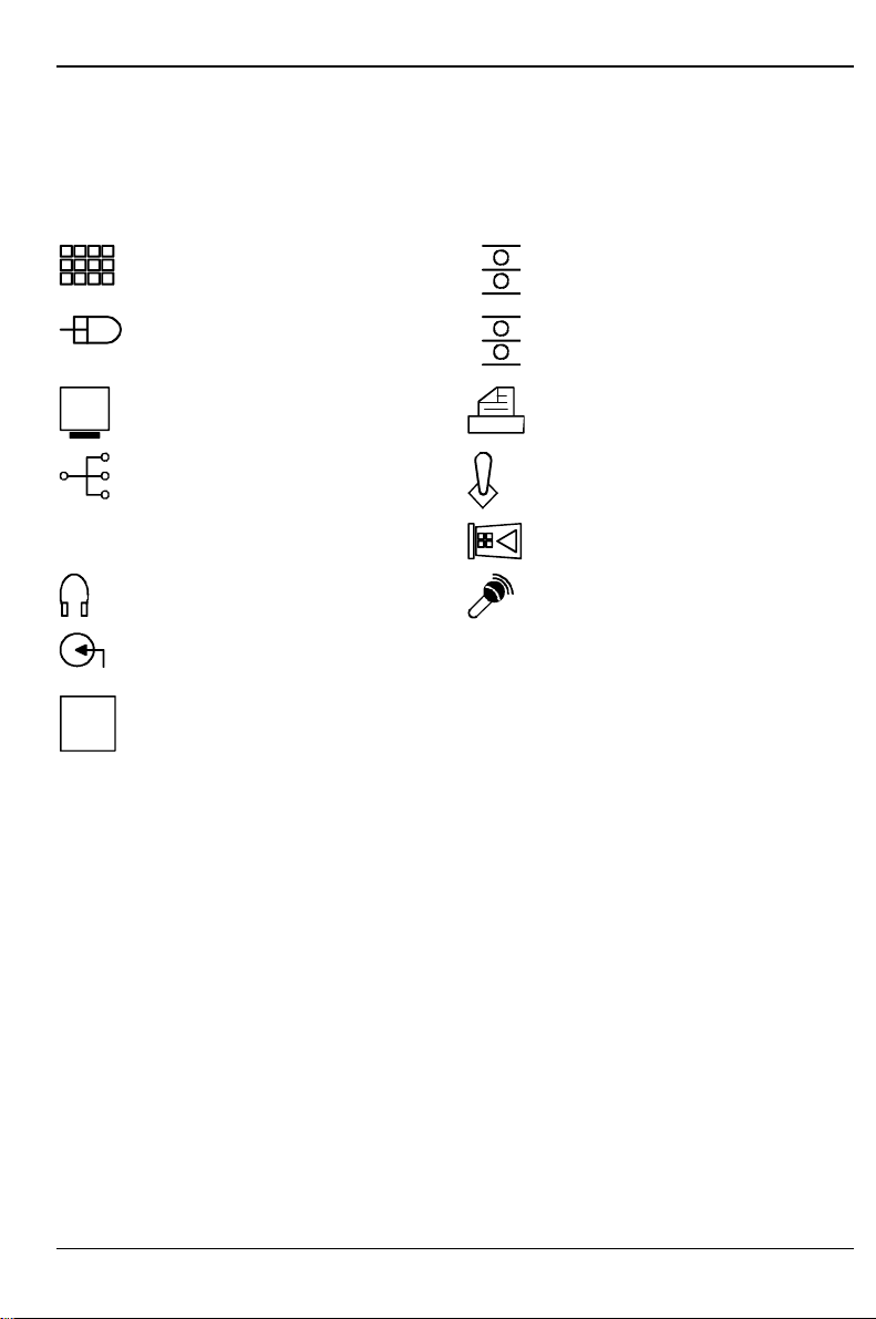
Ports for external devices
The ports for external devices are on the rear and on the front of the system unit. The ports
available on your device depend on the configuration level you have selected. The standard ports
are marked with symbols like those below or similar symbols. Exact details of the position of the
ports are supplied in the Technical Manuals for the boards.
Keyboard port
Serial port 1
PS/2 mouse port
Serial port 2
Video connector Parallel interface
USB - Universal Serial Bus Game port
LAN port Chipcard reader
Audio output (Line out)
Audio input (Line in)
Some of the devices that you connect require special drivers (see the documentation for
the connected device and for the operating system).
i
Microphone jack
A26361-K516-Z100-3-7619
11
Preparation for use and operation Connecting devices
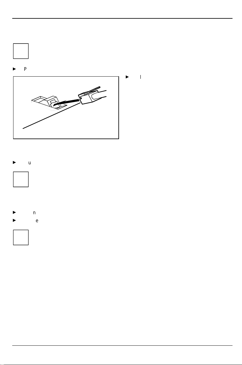
Connecting the keyboard
Use only the keyboard cable supplied.
i
Plug the round plug of the keyboard cable into the keyboard port on the system unit.
Plug the other connector of the keyboard
cable into the socket on the underside of
the keyboard.
Connecting the mouse
Plug the connector of the mouse cable into the mouse port.
If you do not attach a mouse at the PS/2 mouse port, you can disable the mouse
controller in the
i
BIOS-Setup
in order to free the IRQ12 for a different application.
Connecting devices with serial or parallel port
Connect the data cable to the external device.
Connect the data cable of the external device to the appropriate port on the system unit.
Most devices that you connect to the serial or parallel port require special drivers. Your
operating system already includes many drivers . But if the driver you need is not on the
i
hard disk please install it from the floppy disk supplied with the device or with the
application program.
If you need to change the default settings of the serial or parallel port (e.g. address,
interrupt), you can do so in the
described in the Technical Manual for the system board or in the "BIOS Setup" manual.
12
BIOS Setup
. The default setting for the interfaces are
A26361-K516-Z100-3-7619
Connecting devices Preparation for use and operation
Connecting the monitor to the line voltage
Prepare the monitor as described in the Operating Manual for the monitor.
Plug the data cable of the monitor into the monitor port of the system unit.
2
1
Depending on the connector, plug the monitor power cable into either the system unit (1) or the
grounded power outlet (2).
You may only plug the monitor power cable into the monitor connector if the rated current
of the monitor is less than 1.5 A (230 V) or 3 A (115 V). The rated current for the monitor
!
is also given on the monitor itself and in the Operating Manual for the monitor.
A26361-K516-Z100-3-7619
13
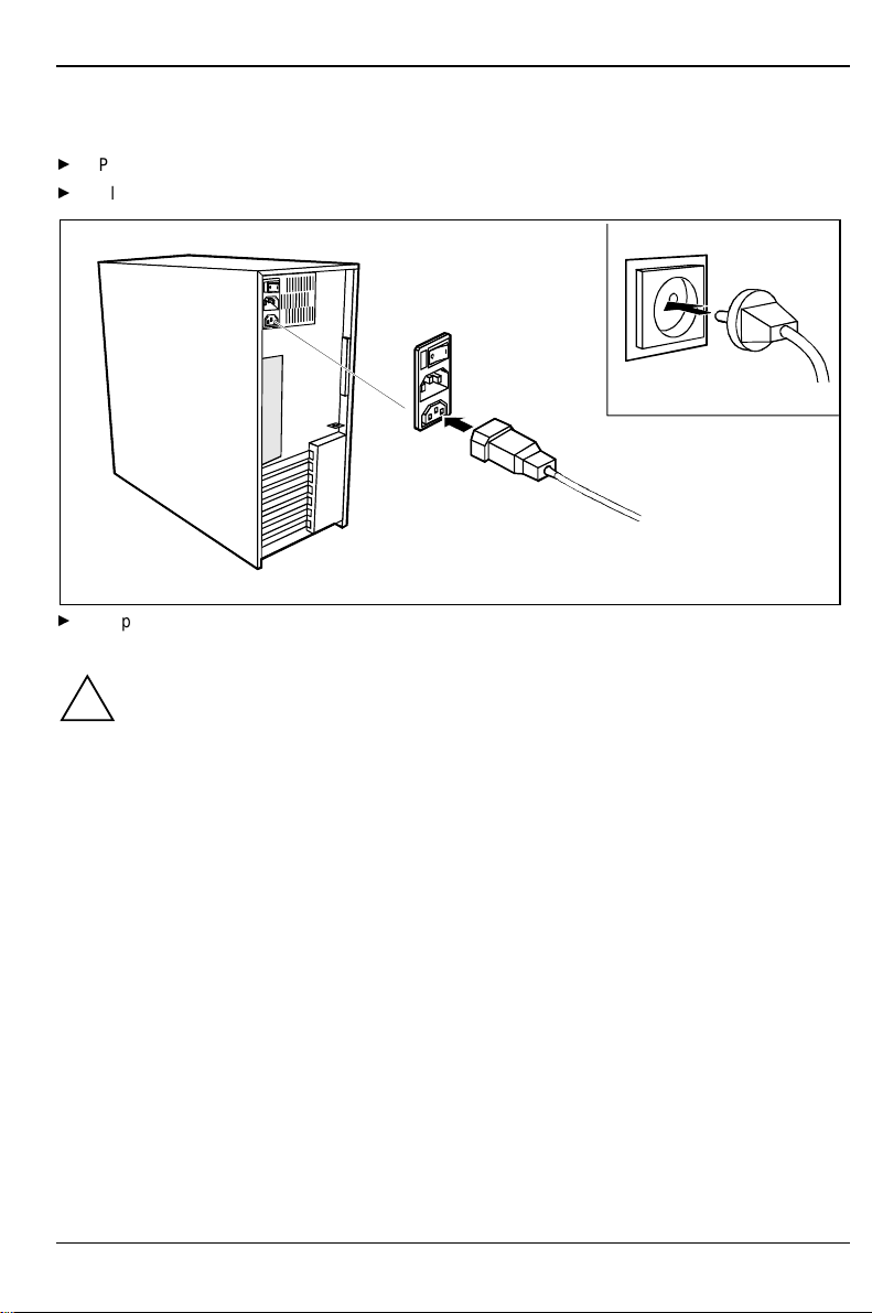
Preparation for use and operation Connecting the PC to the line voltage
Connecting the PC to the line voltage
100 V - 125 V 200 V - 240 V
1 1
1 = Notch for inserting the screwdriver
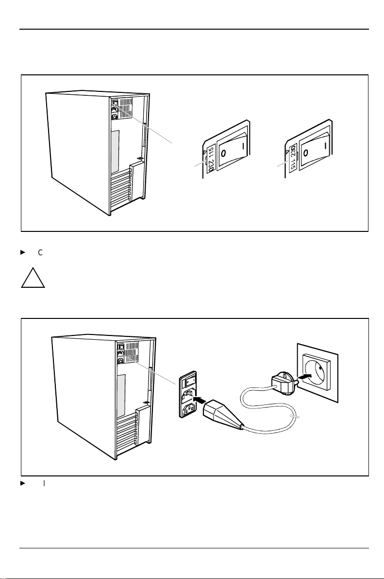
Check the rated voltage.
The value marked with an arrow must agree with the local line voltage:
115 = 100 V to 125 V 230 = 200 V to 240 V
!
If the rated voltage does not agree with the local line voltage, lift out the plug-in unit with a
screwdriver (1), turn it and replace it.
2
1
Plug the system unit's power cable into the system unit (1) and then into the grounded power
outlet (2).
14
A26361-K516-Z100-3-7619

Unlocking/locking the system unit Preparation for use and operation
Unlocking/locking the system unit
With the casing lock you can mechanically lock the system unit, and with the drive cover you can
block access to the drives.
Unlocking the system unit
1
2
Turn the key counterclockwise (1).
Slide the drive cover in direction of the arrow (2).
Locking the system unit
2
1
Slide the drive cover in direction of the arrow (1) and turn the key clockwise (2).
A26361-K516-Z100-3-7619
15
Preparation for use and operation Switching the PC on and off
Switching the PC on and off
0
1
I
3
2
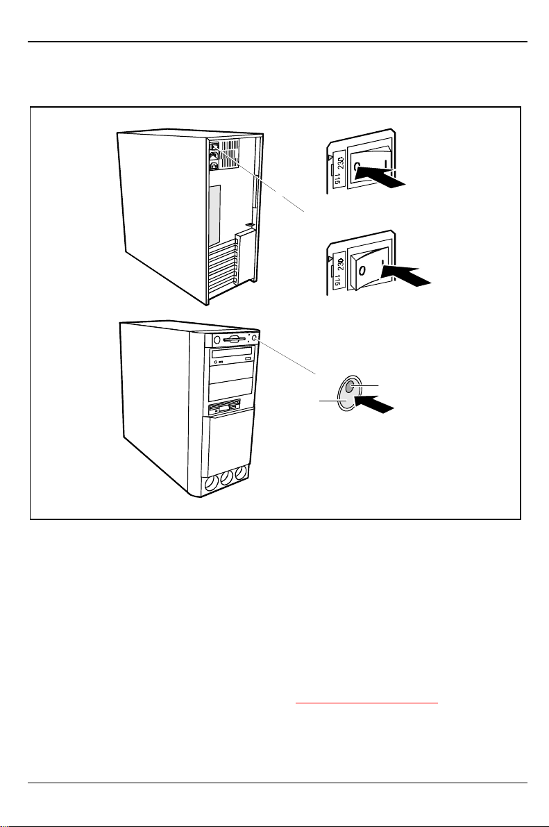
1 = Main switch
2 = ON/OFF switch
3 = Power-on indicator
System unit is off
The main switch (1) is in position 0, the power-on indicator (3) does not light, and the ON/OFF
switch (2) is disabled.
System unit is ready-to-operate
The main switch (1) is in position I and the power-on (3) indicator lights up orange or flashes
green/orange. In this mode, you can switch the system unit on with the ON/OFF switch (2). The
"ready-to-operate" status corresponds to the "stand-by" status of a TV set. The exact description of
the power-on indicator (3) is contained in the section "Indicators on the system unit
System unit is on
The main switch (1) is in position I and the power-on indicator (3) lights up green. The system unit
can be switched ready-to-operate at the ON/OFF switch (2).
16
0 = System unit is switched off
I = System unit is ready-to-operate
".
A26361-K516-Z100-3-7619
Switching the PC on and off Preparation for use and operation
Switching on the PC for the first time
When you switch on your PC for the first time the supplied software is set up and configured.
If the PC is integrated into a network, the user and server details as well as the network
protocol are required. Contact your network administrator if you have any questions about
i
these details.
The license number for Windows is printed on the front cover of the Windows manual
supplied.
Switch your monitor on.
Switch the system unit on with the ON/OFF switch.
The power-on indicator lights green and the PC is started.
While the PC boots, the screen remains dark for up to a minute depending on the system
configuration. To see the start-up messages, you can switch off this standard setting in
!
Adjust the brightness if necessary (see the Operating Manual for the monitor).
!
BIOS Setup
the
Some variants require you to start the software installation by pressing the function key
.
Once the installation has been started the PC must not be switched off.
You should only reboot the PC during installation if you are requested to do so. Otherwise
the installation will be not be performed correctly. If a fault occurs in the installation the
contents of the hard disk must be completely restored.
in the
Quiet Boot
entry.
During installation follow the instructions on the screen.
Consult the operating system manual if there is anything unclear about the requested input data.
Some system configurations do not include a Windows CD in the delivery package. In this case you
should create a backup copy after installing Windows so that you can restore the hard disk contents
in an emergency.
You need about 40 diskettes for this.
Create Windows diskettes with the
them using the labels supplied.
You will find further information about the system, drivers, utilities, updates, and manuals
etc. on the "Drivers & Utilities" CD supplied.
i
A26361-K516-Z100-3-7619
MSCSD
backup program (create system diskettes) and label
17
Preparation for use and operation Switching the PC on and off
Switching on the PC
Switch the monitor on (see the Operating Manual for the monitor).
Switch the system unit on with the main switch at the rear of the system unit.
If the power-on indicator lights orange, press the ON/OFF switch at the front of the system unit.
The power-on indicator lights green and the PC is started.
While the PC boots, the screen remains dark for up to a minute depending on the system
configuration. To see the start-up messages, you can switch off this standard setting in
!
BIOS Setup
the
If you have assigned the system password, you must enter this when requested to do so,
in order to start the operating system.
in the
Quiet Boot
entry.
Switching off the PC
Shut down the operating system properly. Windows in the
If the operating system does not automatically switch the system unit off, switch the system
unit to ready-to -operate by pressing the ON/OFF switch or turn it off by pressing the main
switch when requested to do so.
If the system unit is ready-to-operate, the power-on indicator lights up orange. The system unit
consumes a minimum of energy and can be switched on by an external device (provided that the
remote-on functionality is enabled in
When the system unit is switched off with the main switch the power-on indicator goes off after
approx. 15 seconds. The system unit no longer uses any power.
BIOS Setup
).
Start
menu via the
Quit
function.
The main switch and the ON/OFF switch do not disconnect the system unit from the line
voltage. To disconnect the line voltage completely, remove the power plug from the
i
grounded power outlet.
Switch the monitor off (see the Operating Manual for the monitor).
Placing a PC (with soft power off function) in a ready-to-operate state by means of software
Prerequisite: Your system must support switching off with software and this functionality must be
enabled in
on Windows NT systems.
You can switch your PC ready-to-operate under Windows 9x or Windows NT via the
shutdown the Computer
18
BIOS Setup (Soft Power OFF - Enabled
menu or by using the
DeskOff
). In addition, the soft off software must be installed
program.
A26361-K516-Z100-3-7619
 Loading...