

Page 1

PRIMEPOWER, RM
PRIMESTATION
as LAN Console or System Management Console (SMC)
E. Hübner-Hatzel
Fujitsu Siemens Computers GmbH Paderborn
33094 Paderborn
e-mail: email: manuals@fujitsu-siemens.com
Tel.: (05251) 81 4895
Fax: (++49) 700 / 372 00001
U41270-J-Z916-2-76
Sprachen: En
Edition October 2002
Page 2

Comments… Suggestions… Corrections…
The User Documentation Department would like to
know your opinion of this manual. Your feedback helps
us optimize our documentation to suit your individual
needs.
Fax forms for sending us your comments are included in
the back of the manual.
There you will also find the addresses of the relevant
User Documentation Department.
Certified documentation
according DIN EN ISO 9001:2000
To ensure a consistently high quality standard and
user-friendliness, this documentation was created to
meet the regulations of a quality management system
which complies with the requirements of the standard
DIN EN ISO 9001:2000.
cognitas. Gesellschaft für Technik-Dokumentation mbH
www.cognitas.de
Copyright and Trademarks
Copyright © 2002 Fujitsu Siemens Computers GmbH.
All rights reserved.
Delivery subject to availability; right of technical modifications reserved.
All hardware and software names used are trademarks of their respective manufacturers .
This manual is printed on
paper treated with
chlorine-free bleach.
Page 3

Contents
1 Preface . . . . . . . . . . . . . . . . . . . . . . . . . . . . . . 1
1.1 Target group . . . . . . . . . . . . . . . . . . . . . . . . . . . . 2
1.2 Summary of contents . . . . . . . . . . . . . . . . . . . . . . . 3
1.3 Notational conventions . . . . . . . . . . . . . . . . . . . . . . 4
2 Safety notes . . . . . . . . . . . . . . . . . . . . . . . . . . . 5
3 Functionality . . . . . . . . . . . . . . . . . . . . . . . . . . . 7
3.1 Functions supported as a LAN Console . . . . . . . . . . . . . . 7
3.2 Functions supported as an SMC . . . . . . . . . . . . . . . . . 8
4PRIMESTATION. . . . . . . . . . . . . . . . . . . . . . . . . . 9
4.1 Preinstallation . . . . . . . . . . . . . . . . . . . . . . . . . . . 9
4.2 PRIMESTATION hardware . . . . . . . . . . . . . . . . . . . 11
4.2.1 Power ratings . . . . . . . . . . . . . . . . . . . . . . . . . . 11
4.2.2 Environmental conditions . . . . . . . . . . . . . . . . . . . . 12
4.2.3 Standards . . . . . . . . . . . . . . . . . . . . . . . . . . . . 13
4.3 Startup and operation . . . . . . . . . . . . . . . . . . . . . . 13
4.3.1 Scope of delivery . . . . . . . . . . . . . . . . . . . . . . . . 13
4.3.2 Unpacking and checking the delivery unit . . . . . . . . . . . . 14
4.3.3 Installing the PRIMESTATION . . . . . . . . . . . . . . . . . 14
4.4 Overview of connections . . . . . . . . . . . . . . . . . . . . . 15
4.4.1 Connecting the keyboard . . . . . . . . . . . . . . . . . . . . 16
4.4.2 Connecting the mouse . . . . . . . . . . . . . . . . . . . . . . 16
4.4.3 Connecting devices with a serial or USB interface . . . . . . . 17
4.4.4 Connecting the monitor . . . . . . . . . . . . . . . . . . . . . 17
4.4.5 Connecting the PRIMESTATION to the power supply . . . . . . 18
4.5 Operating the PRIMESTATION . . . . . . . . . . . . . . . . . 20
4.5.1 Switching on/off the PRIMESTATION . . . . . . . . . . . . . . 20
4.5.1.1 System unit is switched off . . . . . . . . . . . . . . . . . . . . 20
4.5.1.2 System unit is in standby mode . . . . . . . . . . . . . . . . . 21
4.5.1.3 System unit is switched on . . . . . . . . . . . . . . . . . . . 21
4.5.2 Displays on the system unit . . . . . . . . . . . . . . . . . . . 21
4.5.3 Pre-installation . . . . . . . . . . . . . . . . . . . . . . . . . . 22
4.5.4 Hard disk partitioning . . . . . . . . . . . . . . . . . . . . . . 23
4.5.5 First booting . . . . . . . . . . . . . . . . . . . . . . . . . . . 24
U41270-J-Z916-2-76
Page 4

C
ontents
5 PRIMESTATION as LAN Console . . . . . . . . . . . . . . . . 25
5.1 Architecture . . . . . . . . . . . . . . . . . . . . . . . . . . . . 25
5.2 Remote Communication Adapter . . . . . . . . . . . . . . . . . 26
5.2.1 Connections on the rear of the RCA . . . . . . . . . . . . . . . 28
5.2.1.1 LAN connection . . . . . . . . . . . . . . . . . . . . . . . . . . 28
5.2.1.2 Serial port for connecting the console . . . . . . . . . . . . . . 29
5.2.2 Cable types . . . . . . . . . . . . . . . . . . . . . . . . . . . . 33
5.2.3 Technical specifications . . . . . . . . . . . . . . . . . . . . . . 33
5.2.3.1 Power ratings . . . . . . . . . . . . . . . . . . . . . . . . . . . 33
5.2.3.2 Environmental conditions . . . . . . . . . . . . . . . . . . . . . 34
5.2.3.3 Dimensions and weights . . . . . . . . . . . . . . . . . . . . . 34
5.2.3.4 Standards . . . . . . . . . . . . . . . . . . . . . . . . . . . . . 34
5.2.3.5 Conformity tests . . . . . . . . . . . . . . . . . . . . . . . . . . 35
5.2.3.6 Approvals . . . . . . . . . . . . . . . . . . . . . . . . . . . . . 35
5.2.4 Switching on the RCA . . . . . . . . . . . . . . . . . . . . . . . 35
5.3 Installing software packages on the LAN Console . . . . . . . . 36
5.4 Configuration . . . . . . . . . . . . . . . . . . . . . . . . . . . 40
5.4.1 Configuring the connected servers . . . . . . . . . . . . . . . . 41
5.4.1.1 Configuring the PRIMEPOWER systems (MR) . . . . . . . . . . 41
5.4.1.2 Configuring the RM systems . . . . . . . . . . . . . . . . . . . 41
5.4.2 Configuring the LAN Console and RCA . . . . . . . . . . . . . 41
5.4.2.1 Initial configuration of the LAN Console and RCA . . . . . . . . 43
5.4.2.2 Configuring the LAN Console . . . . . . . . . . . . . . . . . . . 44
5.4.2.3 Configuring the RCA . . . . . . . . . . . . . . . . . . . . . . . 47
5.4.2.4 New RCA ports . . . . . . . . . . . . . . . . . . . . . . . . . . 54
5.4.2.5 Connecting further RCAs to the LAN Console . . . . . . . . . . 55
5.4.2.6 Connecting another LAN Console to the RCA . . . . . . . . . . 55
5.4.2.7 Modifying the LAN Console and RCA . . . . . . . . . . . . . . 55
5.4.3 Remote boot and installation . . . . . . . . . . . . . . . . . . . 58
5.4.3.1 setup_RM_server . . . . . . . . . . . . . . . . . . . . . . . . . 59
5.4.3.2 bootpconf . . . . . . . . . . . . . . . . . . . . . . . . . . . . . 62
5.4.3.3 add_RM_client . . . . . . . . . . . . . . . . . . . . . . . . . . 62
5.5 Operating the LAN Console . . . . . . . . . . . . . . . . . . . . 66
5.6 Switching LAN Consoles . . . . . . . . . . . . . . . . . . . . . 69
5.6.1 Planned switches . . . . . . . . . . . . . . . . . . . . . . . . . 69
5.6.2 Switching because of problems . . . . . . . . . . . . . . . . . . 70
5.7 Diagnostics . . . . . . . . . . . . . . . . . . . . . . . . . . . . 70
5.7.1 Log files . . . . . . . . . . . . . . . . . . . . . . . . . . . . . . 70
5.7.2 Status information for the rtty monitor . . . . . . . . . . . . . . 71
5.7.3 Configuration entries for the LAN Console . . . . . . . . . . . . 71
5.7.4 RCA system information . . . . . . . . . . . . . . . . . . . . . 72
5.8 Error situations . . . . . . . . . . . . . . . . . . . . . . . . . . 7 2
5.8.1 No response from the RCA . . . . . . . . . . . . . . . . . . . . 72
5.8.2 Failure to establish a connection . . . . . . . . . . . . . . . . . 73
U41270-J-Z916-2-76
Page 5

Conten
ts
5.8.3 Disrupted RCA - LAN Console connection . . . . . . . . . . . 73
5.8.3.1 LAN connection disrupted . . . . . . . . . . . . . . . . . . . . 73
5.8.3.2 No output in console window . . . . . . . . . . . . . . . . . . 74
5.8.4 Invalid password for RCA setup . . . . . . . . . . . . . . . . . 75
5.9 RCA commands . . . . . . . . . . . . . . . . . . . . . . . . . 75
5.9.1 Access rights . . . . . . . . . . . . . . . . . . . . . . . . . . 76
5.9.2 List of commands . . . . . . . . . . . . . . . . . . . . . . . . 77
5.9.2.1 Help command . . . . . . . . . . . . . . . . . . . . . . . . . . 77
5.9.2.2 Port commands . . . . . . . . . . . . . . . . . . . . . . . . . 77
5.9.2.3 Server commands . . . . . . . . . . . . . . . . . . . . . . . . 83
5.9.2.4 Show commands . . . . . . . . . . . . . . . . . . . . . . . . 86
5.9.2.5 User commands . . . . . . . . . . . . . . . . . . . . . . . . . 91
6 PRIMESTATION as SMC . . . . . . . . . . . . . . . . . . . . 95
6.1 Architecture . . . . . . . . . . . . . . . . . . . . . . . . . . . 95
6.2 Upgrading the PRIMESTATION to an SMC . . . . . . . . . . . 97
6.2.1 Hardware upgrade with 2 Fast Ethernet controllers . . . . . . . 98
6.2.2 Use of onboard eri LAN ports . . . . . . . . . . . . . . . . . . 100
6.3 System Console Software (SCS) . . . . . . . . . . . . . . . . 101
6.3.1 Installing SCS . . . . . . . . . . . . . . . . . . . . . . . . . . 101
6.3.2 Operating the SCS . . . . . . . . . . . . . . . . . . . . . . . . 102
7 Teleservice on PRIMESTATION . . . . . . . . . . . . . . . . 103
7.1 Installation and generation . . . . . . . . . . . . . . . . . . . . 104
7.2 Generating the software . . . . . . . . . . . . . . . . . . . . . 105
7.3 Selecting validated Teleservice modems . . . . . . . . . . . . 106
7.4 TeleCall . . . . . . . . . . . . . . . . . . . . . . . . . . . . . 111
7.4.1 Installing Telecall . . . . . . . . . . . . . . . . . . . . . . . . . 112
7.4.1.1 Preparations . . . . . . . . . . . . . . . . . . . . . . . . . . . 112
7.4.1.2 Software installation on the PRIMESTATION . . . . . . . . . . 113
7.4.1.3 Software installation on the RM . . . . . . . . . . . . . . . . . 113
7.4.1.4 Software installation on the PRIMEPOWER . . . . . . . . . . . 113
7.4.2 Generating the Telecall cluster . . . . . . . . . . . . . . . . . 114
Glossary . . . . . . . . . . . . . . . . . . . . . . . . . . . . . . . . . . 117
Abbreviations . . . . . . . . . . . . . . . . . . . . . . . . . . . . . . . 119
Related publications . . . . . . . . . . . . . . . . . . . . . . . . . . . 123
Index . . . . . . . . . . . . . . . . . . . . . . . . . . . . . . . . . . . . 135
U41270-J-Z916-2-76
Page 6

Page 7

1 Preface
The PRIMEST A TION acts as a system console for one or more Fujitsu Siemens
Computers UNIX systems (RM or PRIMEPOWER systems). The server
systems are connected to the PRIMESTATION via V.24/Ethernet converter
located close to the system (max. 15m away) or in the system cabinets.
The PRIMESTATION is based on a high-performance SPARC processor in a
desktop model, which can also be installed and operated in a 19-inch rack using
a rack mounting kit. It is released for the following products:
– RM300/400/600 with Reliant UNIX
– PRIMEPOWER 100N/200/400/600/650/850 (Midrange Server, MR) with
Solaris
– PRIMEPOWER 800/1000/2000 (Enterprise Server, EP) with Solaris
This PRIMEST A TION can be used both as a LAN Console for midrange servers
and as a System Management Console (SMC) for enterprise servers.
The Teleservice port for all networked RM or PRIMEPOWER servers is
managed from the PRIMESTATION (teleservice gateway), which means that
only one line to the Service organization is required for all networked
RM/PRIMEPOWER servers.
Use as a LAN Console for midrange servers
This includes the RM models (300/400/600, ServerNode) and the
PRIMEPOWER midrange server models 100N/200/400/600/650/850. Genuine
LAN Console software is used on the PRIMESTATION for managing the server
systems. The Remote Communication Adapter (RCA) can be used as a
V.24/Ethernet converter. Up to 8 or 16 UNIX servers of Fujitsu Siemens
Computers - dependent on the RCA model - can be connected to this RCA.
Multiple RCAs can be installed. Up to 256 Fujitsu Siemens Computers UNIX
servers (MR) can be managed from the PRIMESTATION.
Use as a system management console (SMC) for enterprise servers
This includes the PRIMEPOWER server models 800/1000/2000. The
PRIMESTATION is used as a system management console (SMC) for these
PRIMEPOWER systems. The SPARC-based PRIMESTATION is a costeffective alternative to an SMC on the basis of a PRIMEPOWER 200 system
console. The PRIMEST ATION is equipped with additional hardware for use as
U41270-J-Z916-2-76 1
Page 8

T
arget group Prefac
e
an SMC. The SCS (System Console Software) software is used as well as the
Console Connection Units (CCU) as V.24/Ethernet converters in the system
cabinets.
If you have a GP7000 F midrange (M200/M400/M600) machine, all of the
PRIMEPOWER (MR) information applies to your machine also, because the
name GP7000F has been changed to PRIMEPOWER.
The midrange models referred to from both system families can be managed in
mixed mode from a PRIMESTATION with the same user interface. The
PRIMESTATION can be operated in parallel as both a LAN console and SMC
assuming the hardware and software configuration supports this.
It is not only possible to use the PRIMESTA TION in its console function but also
for (network-based) system administration, configuration, diagnostics and
software installation and distribution for one or more RM or PRIMEPOWER
(MR) servers. Furthermore, multiple clustered RM or PRIMEPOWER (MR)
servers can be configured, administered and monitored from one console.
Scope of delivery
The PRIMESTATION product consists of a SPARC-based processor with the
Solaris Version 8 operating system, the Solaris Media Kit.
LAN console software (see the chapter “PRIMESTATION as LAN Console”) or
system console software (see the chapter “PRIMESTATION as SMC”) should
be ordered separately.
I The RCA and PRIMESTATION must be ordered separately.
1.1 Target group
This manual is targeted at system administrators. Knowledge of Reliant UNIX
and Solaris systems is required. If any problems occur with the PRIMESTATION, the connected systems or the RCA during system operation, please
contact your local Service organization.
V LAN Console, RCA and SMC are not SIDATA-compatible
The PRIMEST ATION as LAN Console or SMC and RCA do not support
SIDATA, i.e. they must be installed and started up by a technician.
System administrators are given instructions on setting them up and
configuring them.
2 U41270-J-Z916-2-76
Page 9

P
reface Summary of conten
ts
I If you are working with a PRIMEPOWER 200 as SMC, you will find the
description in the SMC manual rather than in this one (see documentation on PRIMEPOWER 2000/1000/800 in the appendix).
1.2 Summary of contents
V Safety notes
It is essential to read the chapter “Safety notes” on page 5 before
starting to work with the PRIMESTATION. This chapter contains
essential information for proper installation and handling of this device.
This manual describes how to install the PRIMESTATION and the RCA and
explains how to configure and operate the PRIMESTATION as a LAN Console
or SMC.
The chapter “PRIMESTATION” on page 9 tells you everything about setting up
and connecting the PRIMESTATION as well as about the preinstallation and
hard disk partitioning.
The chapter “PRIMESTATION as LAN Console” on page 25 explains how to
install the RCA, cable it and start it up. It goes on to describe how to install the
software on the LAN Console from the CD-ROM and how to operate the LAN
Console and RCA. A remote boot/installation is also described. The chapter
also tells you how to replace a PRIMESTATION in the event of error and
provides support for troubleshooting and diagnostics.
The section “RCA commands” on page 75 contains a detailed description of the
commands for the RCA relevant for LAN Console functionality.
The chapter “PRIMEST ATION as SMC” on page 95 describes how to upgrade
a PRIMESTATION to an SMC and the SMC basic configuration.
The chapter “Teleserv ice on PR IMESTATION” on page 103 tells you how to
install and operate Teleservice and Telecall.
You will find other helpful information in the reference chapters “Glossary” on
page 117, “Related publications” on page 123 and “Index” at the end of the
manual.
I Please follow all instructions in the order they appear in this manual. You
will avoid problems by doing so and get along faster. Always pay
attention to the device-specific information that is supplied with the
various devices.
U41270-J-Z916-2-76 3
Page 10

N
otational conventions Prefac
e
1.3 Notational conventions
The following notational conventions are used in this manual:
Monospace This indicates system output, e.g. text on a CRT or
LCD screen (cathode ray tube / liquid crystal
display).
Bold
monospace font
Italics This indicates commands, file names, menu names
Bold This indicates emphasis in the text.
[Key] This indicates keys or key combinations in
This indicates user inputs in examples.
and inputs in continuous text.
continuous text.
I This indicates additional information and tips.
V Title This indicates information, which if not heeded may
jeopardize your health, the functioning of your
system or the security of your data.
Ê This indicates a step that you have to perform.
--> This indicates the last possible solution to a problem
or the last step in a flow chart.
● This character and the one below
– Symbolizes itemized lists.
4 U41270-J-Z916-2-76
Page 11

2 Safety notes
This section gives advice on safety that you have to heed when using your
PRIMESTATION and the RCA.
The devices comply with the relevant safety regulations for information
technology equipment, including electrical machines for use in office environments. Please contact your local sales offi ce or our Service organization if y ou
are in doubt about whether the device can be installed in the environment you
envisage. Also note the safety notes for RM and PRIMEPOWER (MR) and rack
systems.
V Radio Frequency Interference Statement PRIMESTATION
(see also the information in the section “Standards” on page 13 and
page 34)
● The following notice is for EU users only:
This is a product that meets class B of the European standard
EN55022.
● The following notice is for USA users only:
This equipment has been tested and found to comply with the limits
for a Class B digital device, pursuant to Part 15 of the FCC Rules.
These limits are designed to provide reasonable protection against
harmful interference.
V Radio Frequency Interference Statement RCA
(see also the information in the “T echnical specifications” on page 33 and
page 34)
● The following notice is for EU users only:
This is a product that meets European standard EN55022.
● The following notice is for USA users only:
This equipment has been tested and found to comply with the limits
for a Class A digital device, pursuant to Part 15 of the FCC Rules.
These limits are designed to provide reasonable protection against
harmful interference.
U41270-J-Z916-2-76 5
Page 12

s
V Safety notes
● Only transport the device in its original packaging or in other suitable
packaging, which will protect it against impact and jolts.
● Condensation may occur when the device is brought in from the cold
to its site of installation. Wait until the device has reached a stable
temperature and is absolutely dry before putting it into operation.
● Heed the ambient conditions described in the section “Environmental
conditions” on page 12 and for the RCA in the section “Technical
specifications” on page 33 before installing the device and putting it
into operation.
● This device features a safety-tested power cable and may only be
connected to a grounded socket.
● Make sure that the socket on the device or the mains socket on the
housing installation are readily accessible.
● The ON/OFF button does not isolate the device from the mains
voltage completely . To do this, you have to remove the plug from the
mains socket.
● In the case of system units that do not have a main switch, the
ON/OFF button does not disconnect the monitor socket from the
mains supply. A monitor connected to this socket must always be
switched off using its own ON/OFF button.
Safety note
● Lay cables in such a way that there is no danger of people tripping
over them and damaging them. When connecting the device, note the
information given in the section “Connections on the rear of the RCA”
on page 28.
● Do not connect or disconnect communication cables during a
thunderstorm.
● Make sure that no liquids penetrate the interior of the device (risk of
electric shock, short-circuit).
● In cases of emergency (e.g. damage to the housing, controls or
power cable, or penetration of liquid) turn the device of f immediately,
remove the mains plug and notify your sales office or our Service
organization.
● This device may only be repaired by authorized personnel. Unautho-
rized opening of the housing and inadequate repairs may pose a
considerable danger for users (electric shock, risk of ignition).
6 U41270-J-Z916-2-76
Page 13

3 Functionality
This manual describes the functionality of the PRIMESTATION as a LAN
Console or System Management Console (SMC) for UNIX/Solaris servers of
Fujitsu Siemens Computers.
The PRIMESTATION offers the following properties:
1. The PRIMESTATION can be used as a standalone computer system.
2. Input and output are handled via the monitor and keyboard of the
PRIMESTATION.
3. Teleservice connection.
4. The PRIMESTA TION can be equipped with LAN Console software and used
simultaneously as a console on RM and PRIMEPOWER (MR) servers and
with suitable hardware/software upgrades as an SMC for the
PRIMEPOWER enterprise server.
5. The DVD drive of the PRIMESTATION can be used for all connected
systems.
6. The PRIMESTATION can be used as cluster console in high availability
applications with RM an PRIMEPOWER (MR) servers. This may require
additional hardware and software components, which are not part of the
standard configuration of the PRIMESTATION. The console takes over the
function of monitoring the system cluster as a whole and the function of
system console for all connected RM and PRIMEPOWER servers.
3.1 Functions supported as a LAN Console
The PRIMESTATION as a LAN Console can be used to administer
UNIX/Solaris midrange (MR) servers of Fujitsu Siemens Computers. It offers
the following properties:
– It can be used for installation, configuration, admini stration, and diagnostics
management of one or more connected RM or PRIMEPOWER (MR)
servers.
– All functions of a character-oriented display , including IKDB (Internal Kernel
Debugger) and BDM (Board Debug Monitor) or OBP (Open Boot Prom)
Monitor and the rebooting of a system can be carried out from the
PRIMESTATION.
U41270-J-Z916-2-76 7
Page 14

F
unctions supported as an SMC Functionali
ty
– The xscon tool is used to select and represent one or more consoles of RM
and PRIMEPOWER (MR) servers.
– Support for WSA (Web-based System Administration)
– RM and PRIMEPOWER (MR) servers can also be booted and installed
remotely (via LAN).
3.2 Functions supported as an SMC
The PRIMESTATION can be used on PRIMEPOWER enterprise servers as a
System Management Console (SMC) (see also manuals for SMC and System
Console Software in the Related publications section):
– The SMC can check the hardware configuration and the operating status of
the PRIMEPOWER system.
– The SMC performs resource partitioning and in this way allows the shared
use of the processor and storage capacities of the PRIMEPOWER system.
– The SMC supports individual console displays for the different partitions.
– The SMC supports a power supply scheduling system, which allows the
selective switching on and off of the PRIMEPOWER system.
– The DVD drive on the SMC can be used across partitions. This means that
operating systems and applications can be install ed in every partiti on of the
PRIMEPOWER system.
– Clock tuning is performed for every partition of the PRIMEPOWER system
with the SMC clock via the Network Time Protocol (NTP).
– The SMC monitors the entire hardware of the PRIMEPOWER system. If an
error is detected, relevant information is displayed on the SMC. The system
administrator is then notified immediately by e-mail.
8 U41270-J-Z916-2-76
Page 15
4 PRIMESTATION
4.1 Preinstallation
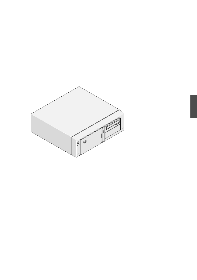
The PRIMEST ATION can be used as a standalone system in desktop housing
with a desktop monitor, standard PC keyboard (German/International) and 3button mouse.
Figure 1: PRIMESTATION as a standalone system
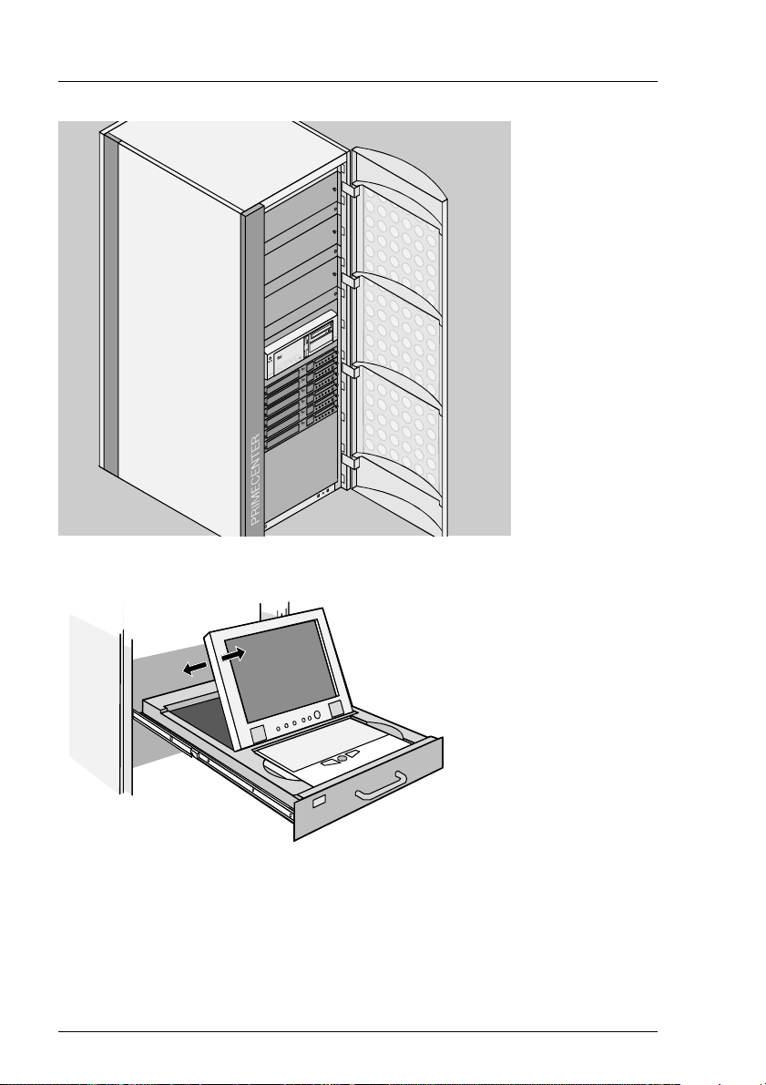
A mounting frame is provided for installing the PRIMESTATION in a 19-inch
rack (3.5 height units), as well as a pull-out rack console with fold-away TFT
monitor (15”/35cm) and keyboard with touchpad.
U41270-J-Z916-2-76 9
Page 16
P
reinstallation PRIMESTATIO
N
Figure 2: PRIMESTATION rack module
Figure 3: Fold-away monitor of PRIMESTATION in the rack
The power supply is enabled when the monitor is tilted open. At the same time,
a safety mechanism on the right hand rear side of the rack module prevents the
rack being pushed back in while the monitor is tilted open.
10 U41270-J-Z916-2-76
Page 17
P
RIMESTATION PRIMESTATION hardwa
re
4.2 PRIMESTATION hardware
The PRIMESTATION is equipped with the following hardware:
Hardware components Configuration/Performance
Processor 500MHz UltraSparc IIe
Main memory 256 MByte (max. 2 GByte possible)
Graphics controller Resolution of 1280x1024 pixels, 24-bit
color, VGA port
DVD drive 12x DVD/40x CD-ROM or better
Diskette drive 1.44 MByte
2 x Fast-Ethernet onboard 2 x 10/100 Mbits/s
2 x hard disks 2 x 20 GByte
2 x serial interfaces COM1 and COM2, DB9 Connector
COM2 for Teleservice
PS/2 interface for 3-button mouse for X-Windows
interface
PS/2 interface for Keyboard German/International
2 x USB
Audio on board
Table 1: PRIMESTATION hardware components
4.2.1 Power ratings
Mains voltage range
(switchable)
Rated frequency 50-60 Hz
Power consumption approx. 60 W
Power factor cosj 120V: >0.90
Table 2: Power ratings
U41270-J-Z916-2-76 11
100V-125V/ 200V-240V
230V: >0.75
Page 18

P
RIMESTATION hardware PRIMESTATIO
N
V Different mains voltages
Note the different mains voltages in Anglo-American countries. You will
find details of this under “Connecting the PRIMESTATION to the power
supply” and for the RCA in the table “Power ratings” on page 33.
4.2.2 Environmental conditions
Environmental conditions for the PRIMESTATION
Climatic class Operation:
(acc. to EN 60721-3-x)
– Temperature (°C):
– Relative humidity (%):
– Height above sea-level (m):
Climatic class Transport:
(acc. to EN 60721-3-2)
– Temperature (°C):
– Relative humidity (%) at 30°C:
– Height above sea-level (m):
Physically active substances (operation): 3M2
Physical environmental conditions:
Operation
Transport
Required space for service activities:
– Minimum distance (mm)
Front:
Rear:
Table 3: Environmental conditions
3K3
5 – 40
5 – 85
3000
2K2
-25 – +60
15 – 98
3000
3M2
2M2
1000
1000
Dimensions and weight Desktop housing Rack module
Breadth (mm):
Depth (mm):
Height (mm):
Weight basic configuration (kg)
Weight SMC (kg)
Table 4: Dimensions and weight
1
without documentation and media kit
1
:
454
456
138
1
11
:
12
449 (with panel 482.6)
456
138 (with panel 152)
11.2
12.2
12 U41270-J-Z916-2-76
Page 19

P
RIMESTATION Startup and operatio
n
4.2.3 Standards
Product safety IEC60950; EN60950
UL60950;CSA60950-00
GS symbol
Immunity to radiation EN55024
Radiated inter-
ference
Approvals GS symbol;
Table 5: Standards
EN 55022-B; EN 61000-3-2; EN 61000-3-3
FCC Class B
CSAUS; CE; CB certificate
c
4.3 Startup and operation
The PRIMESTATION can be used as a LAN Console for one or more RM or
PRIMEPOWER (MR) servers. Up to 256 RM or PRIMEPOWER (MR) servers
can be administrated from one LAN Console.
The PRIMESTATION can also be used as an SMC for PRIMEPOWER enterprise servers. It is recommended to configure one SMC for every enterprise
server. The SMC should always be in the immediate proximity of the server to
allow better servicing.
V Caution
Please refer to the chapter “Safety notes” on page 5.
4.3.1 Scope of delivery
The PRIMESTATION product only consists of the system unit, power supply
cable (grounding type plug) and the Solaris Media Kit actually released for the
PRIMESTATION. The RCA, monitor, keyboard and mouse, the modem for
teleservice (see “Selecting validated Teleservice modems” on page 106) and
the requested cables are not part of the scope of delivery and have to be
ordered separately. The LAN Console software or System Console Software
(SCS) must also be ordered separately.
U41270-J-Z916-2-76 13
Page 20

S
tartup and operation PRIMESTATIO
N
4.3.2 Unpacking and checking the delivery unit
You should keep the original device packaging in case the device has to be
transported.
Ê Unpack all the parts.
Ê Check the package contents for visible transport damage.
Ê Check that the delivery matches the details on the delivery note.
If you discover transport damage or inconsistencies between the packaging unit
and the delivery note, inform your local sales office immediately.
4.3.3 Installing the PRIMESTATION
V Warning
Pay attention to the safety notes when installing the PRIMESTATION.
The PRIMESTATION should only be installed in a specially designated
position. This can be checked from the diagrams on the next pages.
The device should not be subjected to any extreme environmental condi-
tions (see section “Environmental conditions” on page 12). It should be
protected from dust, humidity and heat.
The must be at least 200 mm free space to the front and rear of the
system unit, so that the unit is adequately ventilated. The fan areas on
the monitor and system unit should not be covered.
Do not place any objects over 40 kg in weight on the system unit and do
not stack several system units above one another.
We recommend you position the devices on a non-slip surface. Because
different coatings and varnishes are used on furniture, it is entirely
possible that the plastic feet on the device could damage the surface.
14 U41270-J-Z916-2-76
Page 21
P
RIMESTATION Overview of connection
s
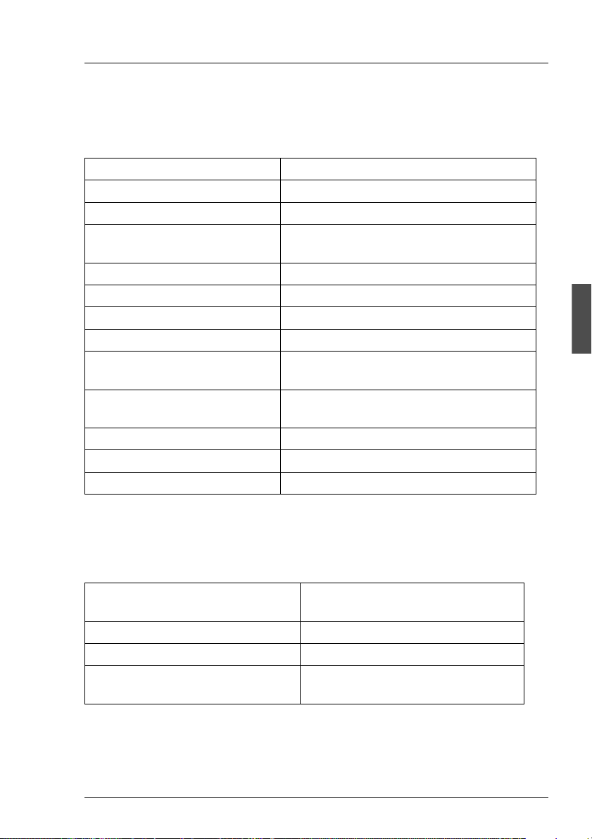
4.4 Overview of connections
The connections are located on the rear of the system unit.
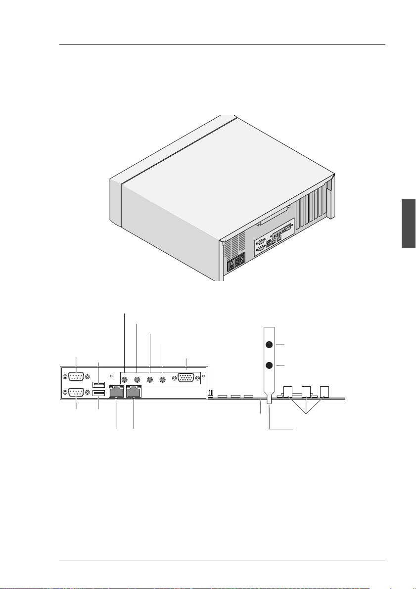
Figure 4: Rear of the PRIMESTATION
Headphone-out (J1)
Line-out (J2)
Line-in (J3)
Serial
port B
USB0
Microphone-in (J4)
Video connector (J5)
PS/2 connector
mouse
PS/2 connector
keyboard
2
1
J24
J25
J23
3
port A
USB1Serial
Ethernet 0
connector
Ethernet 1
connector
AX1105 motherboard
PCI slots on the motherboard
PCI slot cover plate slot 4
Figure 5: Connections on the rear of the LAN Console
V Warning
The power plug must be pulled out!
The cables should neither be plugged in or unplugged during a thunder-
storm (electrical shock).
U41270-J-Z916-2-76 15
Page 22

O
verview of connections PRIMESTATIO
N
Always unplug a cable by its plug. Do not pull on the cable its elf (damage
to plug or socket)!
I You have to install and c onfigure special software (e.g. drivers) for some
of the connected devices (see documentation for the connected device
and for the operating system).
4.4.1 Connecting the keyboard
The keyboard is not part of the scope of delivery of the PRIMESTA TION and has
to be ordered separately.
I Only use the keyboard cable supplied.
Ê Insert the round plug of the keyboard cable into the keyboard port on the
system unit.
Ê Insert the other plug for the keyboard cable i nto the socket on the underside
of the keyboard.
Figure 6: Keyboard connections
4.4.2 Connecting the mouse
Ê Connect the mouse to the mouse port.
16 U41270-J-Z916-2-76
Page 23
P
RIMESTATION Overview of connection
s
4.4.3 Connecting devices with a serial or USB interface
Ê Connect the data cable to the external device.
Ê Connect the data cable of the external device to the corresponding interface
on the PRIMESTATION.
I Most devices that you connect to the serial or Universal Serial Bus (USB)
interface require special drivers. Many drivers are already included in
your operating system. If the required driver is not on the hard disk, you
have to install it from the diskette or CD-ROM, which was supplied with
the device or with the application program.
4.4.4 Connecting the monitor
The monitor is not part of the scope of delivery of the PRIMESTATION and has
to be ordered separately.
Ê Prepare the monitor as described in the Operating Manual for the monitor.
Ê Insert the data cable for the monitor into the monitor port of the PRIMES-
TATION (video connector J5 as shown in figure 5).
2
1
Figure 7: Monitor connection
Ê Connect the power cable for the monitor, depending on the plug, to the
monitor socket on the system unit (1) or to the grounded power outlet (2).
U41270-J-Z916-2-76 17
Page 24
O
verview of connections PRIMESTATIO
N
V Warning
You may only connect the power cable for the monitor to the monitor
socket on the system unit if the power consumption of the monitor is
less than 1.5 A (for 230 V) or 3 A (for 115 V). You will find the values
for the monitor’s power consumption in the technical data for the
monitor itself or in the Operating Manual for the monitor.
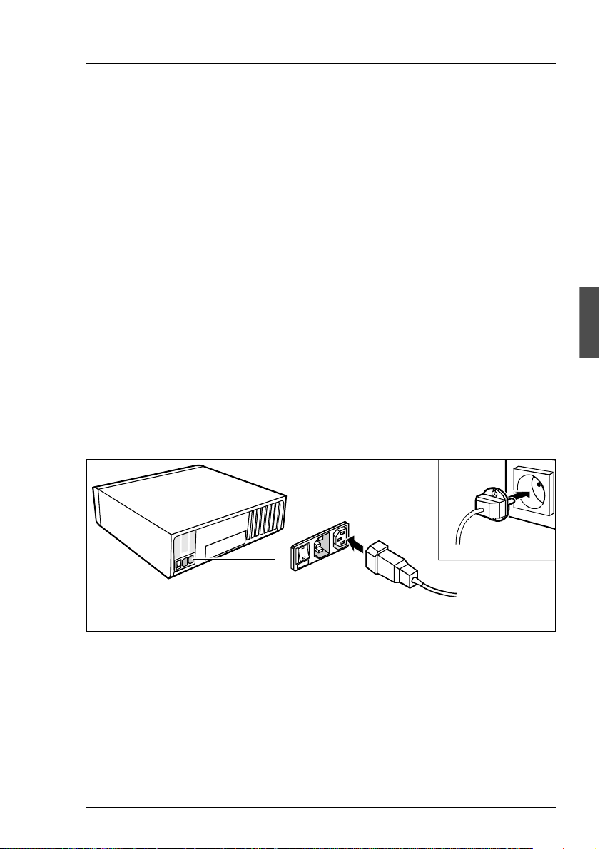
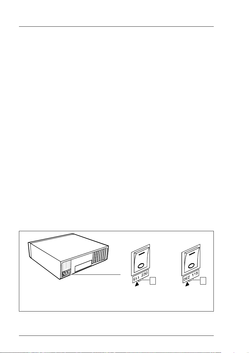
4.4.5 Connecting the PRIMESTATION to the power supply
Ê Check the power supply setting.
V Warning
The value displayed or indicated with the arrow must conform with the
local power supply:
115 = 100 V to 125 V 230 = 200 V to 240 V
Changing the power supply when it is set incorrectly
I Your PRIMES T A TION has a main switch on the rear of the s ystem unit in
addition to the ON/OFF button on the front. The power supply setting is
found beneath this switch.
Ê Unscrew the plug-in element at the groove (1), rotate it and insert it back into
place again.
100 V - 125 V 200 V - 240 V
1 1
Figure 8: Setting the power supply
1= groove for inserting the screwdriver
18 U41270-J-Z916-2-76
Page 25
P
RIMESTATION Overview of connection
s
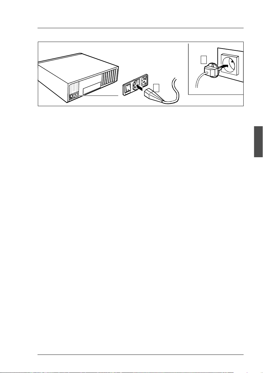
2
1
Figure 9: Connector on system unit
Ê First connect the power cable for the system unit to the P RIMESTATION (1)
and then to the earthed power outlet (2).
U41270-J-Z916-2-76 19
Page 26
O
perating the PRIMESTATION PRIMESTATIO
N
4.5 Operating the PRIMESTATION
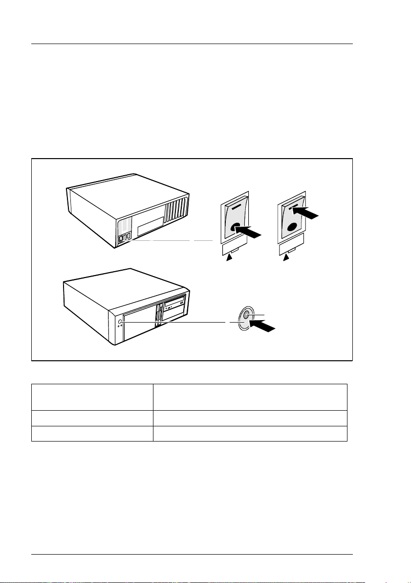
4.5.1 Switching on/off the PRIMESTATION
The PRIMESTATION also has a main switch on the rear of the system unit in
addition to the ON/OFF button on the front.
0
1
2
Figure 10: Switching on/off the PRIMESTATION
1=Main switch O=System unit is switched off
I=System unit is operational
2=On/off button
3=Power LED
4.5.1.1 System unit is switched off
I
3
The main switch (1) is in position O, the power LED (3) is not lighting and the
ON/OFF button (2) is not functional.
20 U41270-J-Z916-2-76
Page 27

P
RIMESTATION Operating the PRIMESTATIO
N
4.5.1.2 System unit is in standby mode
The main switch (1) is in position I and the power LED (3) is not lighting. You
can enable the PRIMEST ATION in this mode with the ON/OFF button (2). The
power LED (3) is described in greater detail in the next section.
4.5.1.3 System unit is switched on
The main switch (1) is in position I and the power LED (3) is lighting green. The
PRIMESTATION can be switched to standby mode using the ON/OFF button
(2).
To do this, press the ON/OFF button for 4 seconds.
I This should only happen from the OBP (Open Boot Prom) or in the event
of an error.
“init 5” should always be used under Solaris to shut down to standby
mode.
4.5.2 Displays on the system unit
4
1
2 3
Figure 11: Free-standing PRIMESTAT ION
1. Power LED
If the power LED is lighting green, the PRIMESTATION is switched on.
The system then switches to the OBP or Solaris is started.
2. Hard disk indicator
U41270-J-Z916-2-76 21
5
Page 28

O
perating the PRIMESTATION PRIMESTATIO
N
The indicator lights when the hard disk drive of the PRIMESTATION is
accessed.
3. Message indicator
This indicator is intended for future applications.
4. DVD-ROM indicator
The indicator lights when the DVD-ROM drive of the PRIMESTATION is
accessed.
5. Diskette indicator
The indicator lights when the diskette drive of the PRIMESTATION is
accessed. The diskette must not be removed under any circumstances while
the indicator is lighting.
4.5.3 Pre-installation
The PRIMESTATION is pre-installed as follows:
Component Pre-installation
Operating system Solaris 8 (entire distribution plus OEM
support 64 bit) incl. Disksuite, SUNVTS™
Patches regard patches as necessary
Teleservice V4.0
Language German
(English is installed automatically as well)
Table 6: Pre-installing the PRIMESTATION
22 U41270-J-Z916-2-76
Page 29
P
RIMESTATION Operating the PRIMESTATIO
N
4.5.4 Hard disk partitioning
The following hard disk partitioning is predefined:
Partition Fold er Hard disk partitioning 20 GByte
0 /(root) overlap - (swap+Partition 6 + Partition 7)
ï
overlap - (swap + 32 MByte)
1 swap 512 MByte
2 overlap Entire disk
3
4
5
6 16 MByte as metadevice
7 16 MByte as metadevice
Table 7: Hard disk partitioning
This hard disk arrangement allows use both as a LAN Console and as an SMC
on PRIMEPOWER enterprise servers.
I The table “Pre-installing the PRIMEST ATION” on page 22 and the table
“Hard disk partitioning” should be referenced for performing a reinstallation. This will save you repartitioning when using the PRIMESTA T ION
as an SMC.
I Solaris 8 4/01 should always be reinstalled using the accompanying
start CD “Operating Environment Installation CD for use with
Solaris 8 4/01 Operating Environment”.
U41270-J-Z916-2-76 23
Page 30

O
perating the PRIMESTATION PRIMESTATIO
N
4.5.5 First booting
Identification
When the system boots for the first time, parameters for identification like host
name, network, time zone and root password are required.
Language setting
When the Solaris operating system has booted and signed off, a mask appears
prompting the user name. The desired language can be chosen in the following
menu:
Desktop Login --> Options --> Languages
Once you have entered the password, the CDE (Common Desktop
Environment) is started.
All other parameters are set using the usual Solaris tools.
24 U41270-J-Z916-2-76
Page 31

5 PRIMESTATION as LAN Console
The PRIMESTATION when used as a LAN Console supports the installation,
configuration, administration and diagnostic management of one or more
connected RM and PRIMEPOWER (MR) servers.
5.1 Architecture
The LAN Console architecture is based on the following components:
● PRIMESTATION with Solaris
● MFII keyboard (German/International) and 3-button mouse
● LAN Console software
● One or more RCAs, to which the LAN Console is connected via the LAN
(TCP/IP)
● RCA3 and RCA4 may be operated in parallel on a LAN Console.
U41270-J-Z916-2-76 25
Page 32

R
CA PRIMESTATION as LAN Conso
le
RM Systems
8 or 16 x V.24
Remote Communication Adapter
RCA
Ethernet TCP/IP
LAN Console
Figure 12: LAN Console architecture
PRIMEPOWER (MR) Systems
5.2 Remote Communication Adapter
A Remote Communication Adapter (RCA) is needed to connect the
LAN Console to the RM and PRIMEPOWER (MR) servers so that it can monitor
and operate these systems. The existing V.24-based serial console interfacing
concept for the RM/PRIMEPOWER (MR) has been retained. The LAN Console
is based on SPARC/Solaris 8 and is connected to the LAN via TCP/IP (see
figure “LAN Console architecture” on page 26). The RCA is available in a
version with 8 ports (RCA4-8) and a version with 16 ports (RCA4). The RCA can
be operated in standalone mode and is also available as a rack mount module.
One or two devices can be installed side by side in the rack in one height unit
using an optional rack installation kit.
26 U41270-J-Z916-2-76
Page 33

P
RIMESTATION as LAN Console RC
A
V RCA does not support SIDATA
The RCA does not support SIDATA and therefore has to be installed by
our Service organization.
The safety aspects of this process are described in the chapter “Safety notes”
on page 5.
I Distinguishing between RCA3 and RCA4
Reference is made in some sections to the previous RCA versions. If a
distinction is needed between the current RCA and previous versions,
the current RCA will be referred to as RCA4 and the previous version as
RCA3.
I Scope of RCA4 and RCA4-8
RCA4 (with 16 ports) and RCA4-8 (with 8 ports) only differ in the number
of ports. Besides hardware and released firmware are identical.
Therefore the devices are compatible.
If in this manual the RCA4 is mentioned, it refers to both devices in the
same way. Otherwise RCA4 (16 ports) or RCA4-8 are explicitly
mentioned.
The current RCA can be ordered under the following order numbers:
RCA RCA4-8 Rack installation kit
D:GPRAC-RC22E D:GPRAC-RC23E D:GPRAC-ZB22E
ET-Nr. 0207162
Table 8: RCA order numbers
You will find the order numbers for the cables you need in the section “Cable
types” on page 33.
V No RCA4 connection on an Intel-based LAN Console
The RCA4 cannot be operated on the previous version of the current
LAN Console (Intel-based). The RCA4 requires the PRIMESTATION
with LAN Console software from FSC Control CD version 02/02.
U41270-J-Z916-2-76 27
Page 34

R
CA PRIMESTATION as LAN Conso
le
5.2.1 Connections on the rear of the RCA
I LAN cables and serial port cables are not included in the package
automatically and have to be ordered separately. Refer to the section
“Cable types” on page 33.
12 222 20 856
12 222 20 856
Figure 13: Connections on the rear of the RCA
1. Port connector 1-8
2. Port connector 9-16 (not with RCA4-8)
3. MAC address and serial number
4. Power supply
V Caution
The power supply should be easily accessible.
5. 10/100BaseT Ethernet connection
5.2.1.1 LAN connection
The RCA has 8 resp. 16 serial ports and allows the administration of up to
sixteen connected FSC Unix server systems via Ethernet 10/100BaseT (LAN
Console).
Simultaneous access to different host computers is enabled by the integrated
TCP/IP software.
The connection is IEEE 802.3 compliant
Connector: 10BaseT (Twisted pair) / RJ45 connection
I Transmission rate: 10 Mbit/s and 100 Mbit/s
28 U41270-J-Z916-2-76
Page 35

P
RIMESTATION as LAN Console RC
A
5.2.1.2 Serial port for connecting the console
The serial ports of the RCA4 have 8-pin RJ 45 connectors.
Transmission rate: 50 Baud to 115.2 Kbit/s
Once you have positioned the RCA in a suitable location or installed it in the
rack,
Ê connect the RCA to the LAN
Ê connect the ports to the server system using the appropriate cable, as
shown in the next diagrams.
V Cables must not prevent the rear door from closing
Always make sure when connecting cables that the rear door of the
system cabinet can be closed again effortlessly.
Ê Secure the connector by tightening its screws.
Connecting to the RM server
Figure 14: Connecting the RCA to the backplane of the device (in this case an RM 600 E45
model)
Ê Connect the cable to the pins which are at the top of the HIOS or EHIOS
basic controller (9-pin).
Ê Insert the connector into the port as shown.
U41270-J-Z916-2-76 29
Page 36

R
CA PRIMESTATION as LAN Conso
le
Connecting to the PRIMEPOWER (MR) server
Correspondingly , the cables are connected to serial port A on the backplane of
the PRIMEPOWER (MR) system cabinet.
PRIMEPOWER 650/850
2
A
5
p
L
o
A
l
I
B
R
u
E
S
KB/MOUSE
2
B
5
p
L
o
A
l
I
B
R
u
E
S
ETHERNET
Figure 15: Connecting the RCA to PRIMEPOWER (MR) rack models
Ê Remove the inserted adapter before connecting the RCA.
30 U41270-J-Z916-2-76
Page 37

P
RIMESTATION as LAN Console RC
A
N
A
L
I
C
R
u
A
B
L
l
A
I
o
R
p
E
5
S
2
B
u
L
B
A
l
I
o
R
p
E
5
S
2
Figure 16: Connecting the RCA to the PRIMEPOWER 200/400/600 vertically or horizontally
PRIMEPOWER 200/400/600
SERIAL A/B
25pol Bu
25pol Bu
RCI
LAN
U41270-J-Z916-2-76 31
Page 38

R
CA PRIMESTATION as LAN Conso
le
Connecting to the PRIMEPOWER 100N
Figure 17: Connecting to the PRIMEPOWER 100N
32 U41270-J-Z916-2-76
Page 39

P
RIMESTATION as LAN Console RC
A
5.2.2 Cable types
The RCA comes with a power cable (1.8m) with Schuko plug (earth contact type
plug). The following serial cables are required for connecting the RCA to the
console port of the RM or PRIMEPOWER (MR) server and must be ordered
separately.
Name Length Order/Part No.
Power cable with rubber
connector for rack installation
Port cable for PRIMEPOWER
(MR) 25-pin DSUB female
Port cable for RM
RJ45 to 9-pin DSUB female
Network cable (LAN) for
connecting to HUB or Switch
Network cable (LAN) for direct
connection (cross over cable)
Table 9: RCA cabling
1.1m D:KB258-C110
2m
10m
5m
15m
2m-100m D:GP7KB-13xx
D:GPRAC-KB04PE16
D:GPRAC-KB04WE16
D:GPRAC-KB04RE16
D:GPRAC-KB04ME16
xx=02/05/10/15/30/50
xx=A0 for100m
D:GP7KB-14xx
(Category5 UTP-Kabel xx
meters, xx=05/10/20/50)
xx=A0 for 100m
5.2.3 Technical specifications
5.2.3.1 Power ratings
Mains voltage range
(autorange)
Nominal frequency 50-60 Hz
Power consumption approx. 20 W
Rated current max. 1A
Table 10: Power ratings
U41270-J-Z916-2-76 33
100V-250V
Page 40

R
CA PRIMESTATION as LAN Conso
le
5.2.3.2 Environmental conditions
Temperature +15 °C to +35 °C
Relative humidity 20% to 75%
Table 11: Temperature
Requisite intake and exhaust air clearance for ensuring sufficient ventilation:
Front min. 100 mm
Rear min. 100 mm
Table 12: Intake and exhaust air clearance
5.2.3.3 Dimensions and weights
Width 225 mm
Height 45 mm
Depth 208 mm
Weight 1 kg
Table 13: Dimensions and weights
5.2.3.4 Standards
Product safety IEC60950
EN60950
UL 1950
CSA 950
Electromagnetic
compatibility
EN 55022, class A
EN 55024
EN 61000-3-2
EN 61000-3-3
FCC part 15 class A
Environmental compatibility EPA-compliant
Table 14: Standards
34 U41270-J-Z916-2-76
Page 41

P
RIMESTATION as LAN Console RC
A
5.2.3.5 Conformity tests
Europe (CE) EU Directive: 89/336/EEC (EMC)
73/23/EEC (product safety)
Table 15: Conformity tests
5.2.3.6 Approvals
Global IEC CB Scheme
Table 16: Approvals
5.2.4 Switching on the RCA
Ê The RCA is switched on by connecting it to the mains.
Power Online Link TRAFFIC 100MBps Reset INT
RCA4
Figure 18: Front view of RCA
Init
V Restart
INIT interrupts operation of the RCA and causes the system to
restart.
The RCA is reset to the default values set at the factory.
If you want to delete the current configuration, press INIT for 5 seconds,
ONLINE flashes slowly . If you want to delete the IP address, press INIT
for a further 5 seconds, ONLINE flashes quickly.
Reset
Interrupts operation of the RCA and reboots it while retaining the values
set.
U41270-J-Z916-2-76 35
Page 42

S
oftware packages on the LAN Console PRIMESTATION as LAN Conso
le
100MBps
lights up if the RCA is connected to a 100 MBps LAN.
TRAFFIC
lights up when there is data traffic.
LINK-LED
lights up if the RCA detects that it is connected to a network.
ONLINE-LED
lights up (does not flash) if the self-test and the initialization phase of the
RCA are run through successfully. If the ONLINE-LED flashes for
approx. 1 minute after it is switched on, an error has occurred in the selftest or during initialization.
POWER-LED
lights up if the RCA is connected to the power supply system.
5.3 Installing software packages on the LAN Console
The LAN Console software needs no more than 10 MBytes of storage space.
The following software packages have to be installed on the LAN Console:
– The LAN Console software is stored on the FSC Control CD (system
management CD) from revision level 02/02. The following packages are
relevant for the LAN Console:
Package
SMAWrtty (communication)
SMAWxsco (console mapping)
SMAWrins (remote installation server)
SMAWtelx (Telecall gate)
– The FSC Supplement CD is required if the LAN Console is t o be i ntegrated
in the WSA cluster.
36 U41270-J-Z916-2-76
Page 43

P
RIMESTATION as LAN Console Software packages on the LAN Conso
le
Installation procedure:
Ê Insert the FSC Control CD. The required packages are installed using the
Webstart wizard.
The File Manager window opens automatically showing the contents of the
CD-ROM.
Figure 19: File Manager window for FSC Control CD
Ê Double-click Installer and click the Next button until you see the following
mask:
U41270-J-Z916-2-76 37
Page 44

S
oftware packages on the LAN Console PRIMESTATION as LAN Conso
le
Figure 20: Installation mask for FSC Control CD
Ê Choose the product “LAN Console II (SPARC) - Default Install”.
The following packages are installed in the /opt/SMAW directory:
– SMAWrtty
–SMAWrins
–SMAWtelx
–SMAWxsco
If you want to use the LAN Console to administer several systems simultaneously in one or more domains, you should also install the licensed “Domain
Admin 2.0” product (see WebSysAdmin / Domain Admin 2.0 manual).
Teleservice 4.0 (SMAWtssv) is already preinstalled.
The SMAWxsco package requires the following Solaris 8 packages, which have
already been installed:
38 U41270-J-Z916-2-76
Page 45

P
RIMESTATION as LAN Console Software packages on the LAN Conso
le
SUNWbnur Networking UUCP Utilities (Root)
SUNWbnuu Networking UUCP Utilities (User)
SUNWdhcsr BOOTP/DHCP Server Services (Root)
SUNWdhcsu BOOTP/DHCP Server Services (User)
With respect to the functionality of the components in the individual packages,
its is assumed that the path /usr/openwin/bin is contained in the PATH
environment variable. This path must be set for root.
I Language settings:
Only the country-specific language settings
– C (Generic US English; 8bit)
– de (Euro German)
are supported (setting as under “Preinstallation” on page 9).
To use a language other than that set by default (e.g. en_GB), the
following change is needed (owner root):
# cd /usr/lib/locale/en_GB/LC_MESSAGES
# ln -s /opt/SMAW/SMAWxsco/locale/en_US/xscon ‘pwd’ /xscon
Starting WSA
You can start WebSysAdmin (web-based system administration) either at shell
level or at desktop level:
– Starting at shell level
You start the user interface in write mode by entering the following at
command level:
/opt/SMAW/bin/wsa hostname
The welcome screen then appears and you proceed as described there
(language setting, root password).
If you only want to invoke the user interface in read mode, enter the
following:
/opt/SMAW/bin/wsa -read only hostname
U41270-J-Z916-2-76 39
Page 46

C
onfiguration PRIMESTATION as LAN Conso
le
A dialog box then appears and you proceed as described there (language
setting, root password, etc.).
– Starting at desktop level
Y ou will find the WSA application on the desktop in the W orksp ace Menu under
Applications -> Application Manager -> System_Admin -> WebSysAdmin.
5.4 Configuration
In order to be able to configure the system, the LAN Console must have been
connected to the RCA via the LAN and the RCA must have been connected to
one or more RM or PRIMEPOWER (MR) servers via a serial port (see figure 13
on page 28).
I The RCA is connected in the private LAN for security reasons.
From the LAN Console, the system administrator manages both the RCA and
the console connections of the attached RM and PRIMEPOWER (MR) servers.
I Distinguishing between RCA3 and RCA4
This manual deals primarily with the configuration of the current RCA4
described in the section “Remote Communication Adapter”. If a
distinction is necessary between the current RCA and previous versions,
the current RCA is referred to as RCA4 and the previous versions as
RCA3.
I Distinguishing between RCA4 und RCA4-8
This description of the configuration of the RCA always refers to the
model with 16 ports. If you are in possession of an RCA4-8 with 8 ports
but you configure ports 9-16, you get an error message not until you call
xscon.
All RCA (1-4) can be operated from the SPARC/Solaris LAN Console in mixed
mode.
40 U41270-J-Z916-2-76
Page 47

P
RIMESTATION as LAN Console Configuratio
n
5.4.1 Configuring the connected servers
5.4.1.1 Configuring the PRIMEPOWER systems (MR)
If you are using the LAN Console instead of a graphical console on a PRIMEPOWER(MR) - including keyboard and mouse - you have to redirect all console
inputs and outputs to serial port A.
A V.24 cable is used to make the connection at port A to the required port on
the RCA in accordance with the description in the section “Serial port for
connecting the console” on page 29, the “Cable types” on page 33 and the
definition in “mklancon - Create LAN Console configuration entries” on page 45.
The Solaris operating system detects which serial port is connected, i.e. no
explicit reconfiguration is required.
The terminal type needs to be set for the console login:
Ê In the /etc/inittab file, set the terminal type xterm in the entry for the console
login:
...:/usr/lib/saf/ttymon -g ... -d /dev/console -T xterm
-l console
The line speed for the RCA (RCA4) ports is set by default to 9600 baud in the
RCA setup routine, see PORT commands in the section “RCA commands”.
5.4.1.2 Configuring the RM systems
The line speed of the respective RCA ports must be set to 19 200 baud for
connecting RM systems to the RCA (RCA4), see “Port commands” on page 77.
5.4.2 Configuring the LAN Console and RCA
This section describes the initial setup of the LAN Console, i .e. the definition of
console accesses to RM and PRIMEPOWER (MR) servers and initial configuration of the RCA.
For an existing LAN Console setup it also describes the addition of further
console connections, configuration of an additional RCA and connection of
another LAN Console to an RCA that has already been configured.
Furthermore, it briefly deals with possible changes to the configuration of the
LAN Console and RCA.
U41270-J-Z916-2-76 41
Page 48

C
onfiguration PRIMESTATION as LAN Conso
le
Only the root user can carry out the configuration steps. The dialog language is
English.
Error situations relating to the configuration are described in the section
“Diagnostics” on page 70.
Create
configuration entry
mklancon
Configuration entry
correct ?
showlancon
yes
Next
configuration entry?
no
Process configuration
data
vi .../<RCA_config_file>
Make the RCA
addressable in the network
mkrca
Switch on RCA
Configure
RCA
xscon
Configuring the LAN console
no
configuration entry
yes
Configuring the RCA
Delete
rmlancon
Figure 21: Configuring the LAN console and the RCA
42 U41270-J-Z916-2-76
Page 49

P
RIMESTATION as LAN Console Configuratio
n
5.4.2.1 Initial configuration of the LAN Console and RCA
I The RCA is connected to the LAN Console in the private LAN for security
reasons.
The initial configuration of the LAN Console and RCA takes place in two steps.
The first step is to define the console access to the RM or PRIMEPO WER (MR)
servers for the LAN Console. In addition, the RCA is made known from the LA N
Console in the private network and configured via the xscon command.
Before a LAN Console and RCA are configured for the first time, certain precautions must be taken and the required information must be made available:
● The network administrator must define the following in the LAN:
– IP address of the LAN Console. The LAN Console must be accessible
using network commands, for example ping.
– Private network between the LAN Console and RCA, including the IP
address and system name of the RCA.
I If the RCA is not operated in the private network, despite the
recommendation to the contrary, it must be located in the same
LAN segment as the LAN Console. The RCA system name may
also have to be made known to the DNS (Domain Name Service)
server in this case.
● Information required about the LAN:
– Subnet mask of the RCA
● Additional information required if the RCA is not in the private network:
– If a gateway has been set up: IP address of the gateway to the subnet of
the RCA
● Ascertain the Ethernet address (MAC address) of the RCA
The MAC address is the hardware address that is used to access a device
initially . The Ethernet address (MAC address) is shown on a sticker attached
to the RCA housing (see chapter “Connections on the rear of the RCA” on
page 28).
U41270-J-Z916-2-76 43
Page 50

C
onfiguration PRIMESTATION as LAN Conso
le
● Define the allocation of RCA ports. With RCA4 COM ports 1-16 are mapped
to port numbers 3001-3016, with RCA4-8 COM ports 1-8 are mapped to port
numbers 3001-3008:
– Allocate the RCA ports to RM PRIMEPOWER (MR) servers.
– Define a symbolic system name for each RCA port/RM/PRIMEPOWER
(MR) server allocation.
5.4.2.2 Configuring the LAN Console
The LAN Console can represent up to 256 consoles on RM or PRIMEPOWER
(MR) servers. When configuring the LAN Console for the first time, the known
console accesses, referred to as configuration entries, can be defined for at
least one RM or PRIMEPOWER (MR) server. This is done with the aid of the
mklancon script specifying the type of RCA (RC A Type), the system name of the
RCA (RCA SystemNa me), the RCA port number to be used (RCA PortNumbe r) and
the console name (ConsoleName). The console name is the logical address of
the RM or PRIMEPOWER (MR) server that is to be administrated. It is advisable
to use the system name of the RM or PRIMEPOWER (MR) server as the
console name.
The showlancon script checks the configuration entries that are created. Config-
uration entries can be removed with the aid of rmlancon. If parameters need to
be changed for a configuration entry , this entry has to be deleted and recreated
with the new data.
Commands
For each of these commands there is a description that you can look up with “
man command name
The commands available on the LAN Console including their description, are
exclusively related to the RCA4 as 16 port version.
44 U41270-J-Z916-2-76
Page 51

P
RIMESTATION as LAN Console Configuratio
n
mklancon - Create LAN Console configuration entries
Syntax:
mklancon [-t <RCA Type>] <RCA SystemName > <RCA PortNumber>
<ConsoleName>
The command arguments determine the RCA port for which a configuration
entry is to be generated.
-t RCA Type
The permitted values are “3” and “4” for the RCA3 or the RCA4. If the t
argument is not specified, a configuration entry is created for the RCA3.
RCA SystemName
The system name of the required RCA.
RCA PortNumber
A unique TCP/IP port number, which is served by the RCA. The port
number must be in the following valid range for the RCA type:
– RCA3: from 3001-3006
– RCA4 (16 ports): from 3001-3016
or admin
– RCA4-8: from 3001-3008
or admin
ConsoleName
The symbolic system name that is going to be used. This name must not
exist already. It has a maximum length of 14 characters and it must
consist of alphanumeric characters only.
The RCA system name should always be input in a uniform way, i.e. always
either with or without a domain suffix (e.g. utopia, not utopia.xxx.xxx.de) in order
to avoid ambiguities with the rmlancon and showlancon commands.
If the port number admin is entered for the RCA4, a configuration entry is
created for administering the RCA4, see also “Configuring the RCA” on
page 47.
To execute the command for an RCA3, a password has to be assigned for the
specified RCA port.
If a configuration entry is created first of all for an RCA type, the RTTY monitor
lanconsole is created for the RCA3 and the RTTY monitor lanconsole1 for the
RCA4.
U41270-J-Z916-2-76 45
Page 52

C
onfiguration PRIMESTATION as LAN Conso
le
rmlancon - Remove LAN Console configuration entr ies
Syntax:
rmlancon {<RCA SystemName > [<RCA PortNumber >]} | -n
<ConsoleName> | -a | -t <RCA Type>
RCA SystemName
All configuration entries belonging to the specified RCA are displayed
and can be removed with “y”.
RCA PortNumber
If a configuration entry is found for the specified TCP/IP port number –
admin is also possible on the RCA4 – which is served by the RCA, it is
displayed and can be removed with “y”.
-n ConsoleName
The configuration entry belonging to the specified symbolic system name
is output and can be removed with “y”.
-a
All configuration entries on the LAN Console for all RCA types are
displayed and can be removed with “y”.
-t RCA Type
The permitted entries are “3” and “4” for the RCA3 and the RCA4. All of
the configuration entries on the LAN Console of the specified RCA type
are displayed and removed with “y”.
46 U41270-J-Z916-2-76
Page 53

P
RIMESTATION as LAN Console Configuratio
n
showlancon - Show the specified configuration entries
Syntax:
showlancon {<RCA SystemName> [<RCA PortNumber>]} | -n
<ConsoleName >| -a| -t <RCA Type>
The command arguments determine which configuration entries are to be
displayed.
RCA SystemName
All configuration entries belonging to the specified RCA are displayed.
RCA PortNumber
If a configuration entry is found for the specified TCP/IP port number –
admin is also possible on the RCA4 – which is served by the RCA, it is
displayed.
-n ConsoleName
The configuration entry belonging to the specified symbolic system name
is output.
-a
All configuration entries of all RCA types on the LAN Console are
displayed.
-t RCA Type
The permitted values are “3” and “4” for the RCA3 and the RCA4. All of
the configuration entries on the LAN Console of the specified RCA type
ate displayed.
Finally the current state of the associated RTTY monitor is displayed (e.g.
NOTRUNNING). If the -a argument is specified, the states of both RTTY
monitors are displayed assuming configuration entries exist for the associated
RCA types (for information on the RTTY monitor, see section “Status information for the rtty monitor” on page 71).
5.4.2.3 Configuring the RCA
T o be configured successful ly , the RCA (RCA4) must be known and also accessible in the LAN, and all serial console connections (V .24 lines) from the RCA to
the required RM or PRIMEPOWER (MR) servers must be implemented.
Since the RCA does not have a keyboard or display of its own, it is configured
from the LAN Console. The RCA is made known for this purpose using the arp
command, which means that it can be addressed after its initial boot, i.e. after
being powered on, from the LAN Console.
U41270-J-Z916-2-76 47
Page 54

C
onfiguration PRIMESTATION as LAN Conso
le
The RCA is configured in three stages:
– The configuration data, i. e. /IP and MAC address, system name is recorded.
– The mkrca script is inv oked in order to mak e the RCA known i n the network.
– The RCA is switched on.
– The configuration data is set in the RCA.
Recording the configuration data
SMAWxsco provides the template file /opt/SMAW/SMAWxsco/misc/setup.tpl for
recording the configuration data, IP and MAC address and the name of the
RCA. Because both the RCA3 and RCA4 can be configured with the current
software, this file contains all of the data for the RCA3 in addition to the information relevant for the RCA4.
I The configuration of an RCA3 is described in the previous version of this
manual (LAN Console, Order Number U41224-J-Z916-1-76).
Ê Copy this file to any work file.
V Do not modify the template file
The template file itself should not be modified so that it is available to
configure other RCAs.
Ê Now fill in the work file using an editor.
Y ou will need to refer here to the information provided about the network and
RCA at the start of the section “Commands” on page 44.
The content of the work file - as described in Template file
/opt/SMAW/SMAWxsco/misc/setup.tpl - is analyzed by a shell and loaded,
i.e. the entries must comply with the shell syntax rules (e.g. values must
follow straight after the “=” character). Syntax and/or plausibility errors are
reported and cause the respective script to terminate.
I As usual in the shell, comments are indicated by a preceding “#”.
Template file /opt/SMAW/SMAWxsco/misc/setup.tpl
# Configuration Template for RCAs setup.ini
#
# fill in like: KEY=value
# ethernet address: 6 2-digit hex values separated by a
# colon (00 - FF)
# ip address: 4 numeric values separated by a dot
48 U41270-J-Z916-2-76
Page 55

P
RIMESTATION as LAN Console Configuratio
n
# (0 - 255)
#
_____________________________________________________________
#
# # RCAs network configuration
#
RCA_MAC= # ethernet (HW) address of RCA
(08:00:06:0a:f4:0b)
RCA_IP= # ip address of RCA (129.103.165.66)
RCA_IP_Name= # host name of RCA (akkord)
#
#============================================================
#
# # ONLY RCA3:
RCA_Netmask= # ip netmask of RCA (255.255.255.0)
RCA_Domain= # domain suffix (pdb.siemens.de)
RCA_Gateways= # no / yes (default no) (0 | 1)
RCA_Use_DNS= # no / yes (default no) (0 | 1)
#
#
#____________________________________________________________
_
#
# # if using gateways : address of 1st gateway
#
RCA_Gateway_IP= # ip address of RCAs gateway (129.103.165.1)
#
#
_____________________________________________________________
#
# # if using DNS : addresses of the name server
#
DNS_IP1= # ip address of name server 1 (129.103.145.11)
DNS_IP2= # ip address of name server 2 (129.103.145.11)
DNS_IP3= # ip address of name server 3 (129.103.145.11)
DNS_IP4= # ip address of name server 4 (129.103.145.11)
DNS_IP5= # ip address of name server 5 (129.103.145.11)
DNS_IP6= # ip address of name server 6 (129.103.145.11)
#
#
_____________________________________________________________
#
# # determine which TCP/IP port
# # should be served as a console
#
TCP_Port_3001= # no / yes (default no) (0 | 1)
TCP_Port_3002= # no / yes (default no) (0 | 1)
TCP_Port_3003= # no / yes (default no) (0 | 1)
U41270-J-Z916-2-76 49
Page 56

C
onfiguration PRIMESTATION as LAN Conso
le
TCP_Port_3004= # no / yes (default no) (0 | 1)
TCP_Port_3005= # no / yes (default no) (0 | 1)
TCP_Port_3006= # no / yes (default no) (0 | 1)
#
#
What has been described so far is a general overview of the configuration. What
follows is a step-by-step guide of what else has to be done.
Ê The following entries have to be made in your work file (RCA_config_file):
Keyword # Comment (Example)
----------------------------------------------------------------
RCA_MAC= # ethernet (HW) address of RCA
(08:00:06:0a:f4:0b)
RCA_IP= # ip address of RCA (129.103.165.66)
RCA_IP_Name= # host name of RCA (akkord)
The syntax of the Ethernet and IP address is checked:
Ethernet: xx:xx:xx:xx:xx:xx xx = 2-digit hex value
IP: x.x.x.x x = Decimal value (0 <= x <= 255)
Addressing the RCA in the network
The RCA is made accessible in the LAN by executing the mkrca script. The arp
command and the IP and MAC address recorded above as well as the RCA
system name are used here.
The mkrca script uses the work file referred to under “Template file
/opt/SMAW/SMAWxsco/misc/setup.tpl” on page 48 as a call parameter.
50 U41270-J-Z916-2-76
Page 57

P
RIMESTATION as LAN Console Configuratio
n
mkrca - Address the RCA
Syntax:
mkrca [-t <RCA Type>] <RCA config_file>
-t RCA Type
The permitted values are “3” and “4” for the RCA3 or the RCA4. If no t
argument is specified, an RCA3 is configured.
RCA config_file
The RCA_config_file command argument defines the file that the user
copied from the template and filled by means of the setup template
named setup.tpl. The content is analyzed by a shell and loaded, i.e. the
entries must comply with the shell syntax rules (e.g. values must follow
straight after the “=” character). Syntax and/or plausibility errors are
reported and cause the script to terminate.
The mkrca script creates a configuration entry <RCA SystemName>adm in
addition for the RCA4 with admin as the RCA port number. This configuration
provides administration access to the RCA4. If the script cannot create this
administration access, it should be created retrospectively using the mklancon
script.
After the RCA has been switched on for the first time and has passed its boot
phase, it can be accessed from the LAN Console, for example using ping.
RCA access
I You will find an overview of all available RCA commands in the section
“RCA commands” on page 75.
An authentication check is generally performed for accessing the RCA4, i. e. the
user name and password must first be entered correctly before the RCA can be
used. This authentication check can be enabled and disabled for setting up
console connections.
The Admin administrator is predefined in the RCA with all extensive rights,
comparable with the user root on Solaris systems. In addition, additional users
can be created in the RCA with different rights - see “User commands” on
page 91. A maximum of 64 users can be administered in the RCA.
The user name and password must be specified when setting up a console
connection where an access check is in operation in the RCA.
U41270-J-Z916-2-76 51
Page 58

C
onfiguration PRIMESTATION as LAN Conso
le
It is therefore recommended - as described under “Configuring the RCA” on
page 52 - to create a superuser for all configured console connections in the
RCA. This user should have exclusive rights to set up console connections for
all RCA ports and be able to issue a BREAK to the target system via an open
channel. This user, in particular, cannot reconfigure the RCA and also cannot
reboot the RCA because of restricted rights.
Configuring the RCA
The RCA is configured from the LAN Console using the administration access
mentioned above and the xscon component described in the section “Operating
the LAN Console” on page 66. In addition to specifying the RCA netmask, the
administrator password must be assigned and the port parameters must be set
for this configuration.
Syntax:
xscon <RCA AdministrationAccess>
RCA AdministrationAccess
The administration access to the RCA4 created under mkrca or explicitly
with mklancon is referred to in general as <RCA SystemName >adm.
The RCA can also be administered if necessary using telnet:
Syntax:
telnet <RCA SystemName>
RCA SystemName
The system name of the required RCA
Once the connection has been set up, the user name Admin must be specified
for initial access; the password has not been assigned at this point, i.e.
<RETURN> should be pressed.The netmask of the RCA is then requested and
the password for the Admin user must be reassigned. This concludes the initial
configuration of the RCA - the connection to the RCA is not yet terminated
however.
The user named under “RCA access” on page 51 is now created for the console
connections.
Syntax:
user add <User> <Password> access=pall,break
52 U41270-J-Z916-2-76
Page 59

P
RIMESTATION as LAN Console Configuratio
n
User
Freely assignable user name - see “T eleservice on PRIMEST ATION” on
page 103
Password
Password for this user (in plain text) - see
“Teleservice on PRIMESTATION” on page 103
It is possible when a connection is being set up to branch to the Command Line
Interface (CLI) of the RCA. For example, this allows a BREAK to be issued to
the target system. The CLI access sequence is defined as [CTRL] “]” with the
next command.
Syntax:
server cli char=^]
The same values are predefined for all ports of the RCA in this initial configuration:
Speed 9600 baud
Word size 8 bits
Parity None
Stop bits 1
Flow control XON/XOFF
Automatic connection setup No
Syntax:
port all set baud=9600 size=8 parity=none stop=1 flow=xon
timeout=0
I The line speed must be set to a speed of 19200 baud for every relevant
port when connecting RM systems to the RCA. This can be done - even
retrospectively - with the PORT command (see “Port commands” on
page 77).
The first port of the RCA must then be released for use as a console connection
- see “Port Set” on page 80.
U41270-J-Z916-2-76 53
Page 60

C
onfiguration PRIMESTATION as LAN Conso
le
Syntax:
port 1 set cli=off
The next query as to whether the RCA should be rebooted should be answered
with ’y’. The administration window is closed and the RCA reboots. This
concludes the configuration of the RCA.
I ● If the RCA is not operated in a private network - as stipulated for
security reasons - and if it is to be accessible via a gateway, the
gateway address should be entered in the RCA as described in the
command “Server Set” on page 86.
● If the RCA was initialized - see “Init” on page 35 - all parameters listed
here must be reset.
5.4.2.4 New RCA ports
Configuration entry
for <port number RCA>
mklancon
Configuration entry
correct ?
showlancon
Another
configuration entry?
Figure 22: New RCA ports
New ports on the LAN console
no
configuration entry
yes
yes
Delete
rmlancon
Further configuration entries for an existing LAN Console are created by means
of the mklancon script - as shown in the figure “Configuring the LAN console and
the RCA” on page 42 and “mklancon - Create LAN Console configuration
entries” on page 45.
If the newly created configuration entries relate to RM system connections, the
speed should be set to 19200 baud for the relevant port in the RCA4.
54 U41270-J-Z916-2-76
Page 61

P
RIMESTATION as LAN Console Configuratio
n
If configuration entries are to be created for the RCA3, a password has to be
assigned for the specified port for each new entry in mklancon. This password
has to be notified to the RCA by entering it under the appropriate port number
on the “Ports” screen page in the RCA setup routine (see manual LAN Console
U41224-J-Z916-1-76).
Existing configuration entries can be checked, removed and c hanged in the way
described in the section “Configuring the LAN Console” on page 44.
5.4.2.5 Connecting further RCAs to the LAN Console
Another RCA is configured in basically the same way as described for an ini tial
configuration in the section “Initial configuration of the LAN Console and RCA”
on page 43. First, configuration entries should be created for the existing LAN
Console using the new RCA as described under “mklancon - Create LAN
Console configuration entries” on page 45.
The RCA is configured in keeping with the section “Configuring the RCA” on
page 47.
Finally, the RCA has to be activated and configured as described under
“Addressing the RCA in the network” on page 50 and “RCA access” on page 51.
5.4.2.6 Connecting another LAN Console to the RCA
To configure another LAN Console connected to an existing RCA, all configuration entries for the existing LAN Console must also be created on the
additional LAN Console with the same parameter settings. You can check the
necessary information about existing configuration entries with the showlancon
command. The entries on the new LAN Console are again created with
mklancon - see the section “Configuring the LAN Console” on page 44.
5.4.2.7 Modifying the LAN Console and RCA
The following sections outline the approach to modifying a configuration entry
on the LAN Console and the RCA4. The steps for removing a LAN Console or
RCA configuration are also outlined.
Modifying the configuration entry for an RCA port
Ê Remove the configuration entry with rmlancon and use mklancon to create the
modified configuration entry.
U41270-J-Z916-2-76 55
Page 62

C
onfiguration PRIMESTATION as LAN Conso
le
Modifying the RCA configuration
Changes can be made to the RCA configuration using the xscon command:
Syntax:
xscon <RCA AdministrationAccess>
RCA administration access
The administration access to the RCA4 created under mkrca or explicitly
using mklancon is referred to in general as <RCA SystemName >adm.
The user name Admin should be used for logging on to the RCA.
The main commands for configuring the RCA are listed in the section “RCA
commands”. The RCA command HELP provides an initial overview.
If you are using the LAN Console on an RM system, the line speed for the
connected RCA port should be set to 19200 baud in the RCA setup, see “Port
commands”.
RCA firmware updates
New firmware versions for the RCA4 are available under
http://service.fujitsu-siemens.com/support/primestation/RCA4.
Additional installation information is also provided here for every firmware
version and must be observed.
The firmware is updated via an TFTP server (Solaris system). The update is
executed via the administration access to the RCA - see above - by means of
the RCA command
server flash boot|app hostip=<Adresse TFTP-Server>
image=<Name of Image
>
See “RCA commands” on page 75
Removing a LAN Console
Ê Remove all configuration entries, for example using
rmlancon -a
Access can be cancelled for the RCA4 using the
arp -d <RCA SystemName>
command.
Ê Uninstall all software packages of the LAN Console software product.
56 U41270-J-Z916-2-76
Page 63

P
RIMESTATION as LAN Console Configuratio
n
Removing an RCA
Ê For every connected LAN Console, remove a ll configurati on entries for this
RCA (see section “Diagnostics” on page 70) and cancel access for the RCA
using the arp command (see above). The removed RCA can be returned to
the state it was in when delivered if required (see “Switching on the RCA” on
page 35).
U41270-J-Z916-2-76 57
Page 64

R
emote Boot und Installation PRIMESTATION as LAN Conso
le
5.4.3 Remote boot and installation
This chapter only describes the steps and commands that are needed to use
the LAN Console as a boot and installation server for RM machines. What
needs to be done to set up the LAN Console as a boot and installation server
for Solaris machines (e.g. PRIMEPOWER (MR) servers) can be referenced in
the manuals entitled “Solaris Installation Library” and “Solaris Advanced Installation Guide”. The required steps and commands are described there. User and
service manuals for the PRIMEPOWER system are listed in the section
“PRIMEPOWER publications” on page 129.
V SMAWrins must be installed
The SMAWrins package must be i nstalled on the LAN Console no matter
whether an RM system or a PRIMEPOWER (MR) system is connected
because tools from the SMAW rins package are also used when the
BOOTP service is activated for the RCA (see “Addressing the RCA in the
network” on page 50).
Only the RM600 Exx (apart from the E20/E60 models) from Reliant UNIX V5.45
on can be booted and installed over a LAN.
Remote boot and installation are not started from the LAN Console’s CD drive
but from the hard disk. The prerequisite for this function is that the SMAWrins
package has been installed from the FSC Control CD and that there is enough
disk capacity to hold the data for the installation process (500-650 MB per
version).
It is possible to provide different operating system versions on a server in
parallel.
Special shell scripts are available to make it easier to set up a s erver. They are
shipped with the SMAWrins package and are located on the system under the
/opt/SMAW/SMAWrins/bin path. The following scripts are available:
setup_RM_server
This sets up an RM boot and installation server on the LAN Console.
bootpconf
This starts the DHCP service in BOOTP mode on the LAN Console.
add_RM_client
This is used to set up and remove clients for remote installation on the
LAN Console.
58 U41270-J-Z916-2-76
Page 65

P
RIMESTATION as LAN Console Remote Boot und Installatio
n
These scripts do not support NIS (Network Information Service) or NIS+
(Network Information Service Plus). This means there must be a file named
/etc/hosts on the server or DNS must be running.
Refer to the Installation Manual for the RM600, particularly the chapter on
remote installation there.
5.4.3.1 setup_RM_server
Prerequisites:
1. If Volume Management (/etc/init.d/volmgt) has not been started (vold is
not running), you have to manually mount the CD-ROM containing the
Reliant UNIX operating system before starting the setup_RM_server
command.
2. nfs must be running. It must be possible to use the share and mount
commands. This means /usr/lib/nfs/mountd and /usr/lib/nfs/nfsd must be
running (started from /etc/rc3.d/S15nfs.server or from /etc/init.d/nfs.server if
/etc/dfs/dfstab contains entries). More information on this is given in the
“NFS Administration Guide” for Solaris.
3. There must be enough free space in /tftpboot to store the boot files (sash,
Miniroot and unix). These take up about 30 Mbytes for each operating
system version that is going to be installed.
If there is not enough space, an attempt is made with nfs to mount the
data from /var/sadm/remote/cdrom/BOOT (or from /var/sadm/remote/
<VERSION>/cdrom/BOOT) to /tftpboot (or to /tftpboot/<VERSION>). If this
does not work (because, for example, /tftpboot already contains other
data), you should mount a disk partition onto /tftpboot with enough space
for all the data.
V No links
Since the TFTP service is started in security mode, you cannot
use hard or symbolic links here.
4. There must be enough free space in /var/sadm to copy the data from the
CD-ROM containing Reliant UNIX (500-650 MB per operating system
version). Alternatively you can set a symbolic link, for example:
ln -s /export/home var/sadm/remote/<VERSION>
U41270-J-Z916-2-76 59
Page 66

R
emote Boot und Installation PRIMESTATION as LAN Conso
le
Syntax:
setup_RM_server [-V VERSION]
A Solaris system can be set up as a boot/installation server for an RM with the
setup_RM_server tool.
-V
In this case multiple versions of Reliant UNIX can be prov ided in parallel
on the LAN Console for remote installation of the RM devices.
The data for installing the version VERSION is stored under
/var/sadm/remote/<VERSION>/cdrom.
The files for booting the version VERSION are stored under
/tftpboot/<VERSION>/.
The value of the VERSION variable must comply with a specific syntax
consisting of the letter from the computer ID (N or Y), the last digit of the supplementary version (3 for 5.43, 4 for 5.44, 5 for 5.45), the letter of the revision l evel
and the digits of the source patch level, object patch level and produc tion level
(C3004 for 5.43 C30, C1013 for 5.44 C10).
This syntax is important because the installation scripts on the RM ascertain
precisely this variable from the UNIX that was booted for the i nstallation process
and then use this variable to search through the path on the server for the data
for the required NFS (Network File System) mount.
Parameter -V not specified:
In this case only one version of Reliant UNIX can be provided on the Solaris
system for remote installation of RM machines.
The data for the installation is stored under /var/sadm/remote/cdrom.
The files for booting are stored directly under /tftpboot.
Procedure in the system
1. Check and start the rarpd service
2. Start DHCP in BOOTP mode by calling bootpconf
3. Check and start the tftpd service
4. Create the directories /var/sadm/remote and /var/sadm/remote/cdrom and the
directories /var/sadm/remote/<VERSION> and
/var/sadm/remote/<VERSION>/cdrom
60 U41270-J-Z916-2-76
Page 67

P
RIMESTATION as LAN Console Remote Boot und Installatio
n
5. Mount the Reliant UNIX operating system CD-ROM, check it and copy it to
disk. If the /var/sadm file system does not have enough space for the copy,
this is detected and reported.
The following possibilities are offered at this point:
– /var/sadm/remote or /var/sadm/remote/<VERSION> is a symbolic link to
another file system, which does have enough space.
– A separate file system with enough space has been mounted under
/var/sadm/remote.
6. Write entry in /etc/dfs/dfstab and NFS sharetab for the installation directory
(/var/sadm/remote or the directory to which the symbolic link points).
7. Copy the boot files to /tftpboot or /tftpboot/<VERSION>. If the /tftpboot does
not have enough space for the copy, this is detected and reported.
The following possibilities are offered at this point:
– An attempt is made with nfs to mount /var/sadm/remote/cdrom/BOOT or
/var/sadm/remote/<VERSION>/cdrom/BOOT under /tftpboot or
/tftpboot/VERSION. Copying of the data is then inapplicable.
– If the first point does not work, you have to manually mount a separate
file system with enough space under /tftpboot.
U41270-J-Z916-2-76 61
Page 68

R
emote Boot und Installation PRIMESTATION as LAN Conso
le
5.4.3.2 bootpconf
Syntax:
bootpconf [-u]
The bootpconf tool is used to start or stop the DHCP service in BOOTP mode on
the LAN Console. If you input the command without parameters the DHCP
service is started in BOOTP mode.
-u
(unconfigure). If the DHCP service has been started with bootpconf, it is
now stopped.
V Configuration files being deleted
In addition, all configuration files under /var/dhcp are deleted, the links to
/etc/rc[0-3,S]/[KS]34dhcp are deleted, the dhcpd options in /etc/init.d/dhcp
are reset and the /etc/default/dhcp configuration file is deleted.
Procedure in the system
1. Stop the DHCP service if it is running.
2. Create the /etc/default/dhcp file.
3. Enter the dhcpd options in /etc/init.d/dhcp (-o 10 -b manual).
4. Create the DHCP serv ice configuration table /var/dhcp/dhcptab with
dhtadm -C.
5. Create the local DHCP network table /var/dhcp/xxx_xxx_xxx_xxx with
pntadm -C, empty at present.
6. Create or update the local LAN macro in /var/dhcp/dhcptab with
dhtadm -A -m xxx.xxx.xxx.xxx -d ":Subnet=${SUBNET_IP}:Router=
${ROUTER_IP}:"
7. Define links from /etc/init.d/dhcp to /etc/rc[0-3,S]/[KS]34dhcp.
8. Start the DHCP service in BOOTP mode.
5.4.3.3 add_RM_client
Format 1:
add_RM_client -i IP_ADDR -e ETHER_ADDR [-g GATEWAY_ADDR]
-s SUBNETMASK -m MACRO -b BOOT_FILE CLIENT_NAME
62 U41270-J-Z916-2-76
Page 69

P
RIMESTATION as LAN Console Remote Boot und Installatio
n
A client for the BOOTP service is entered on the LAN Console with the
add_RM_client tool.
Options:
-i IP_ADDR
The IP address of the RM client that is going to be entered for remote
installation. This is specified in the usual Internet format: xxx.xxx.xxx.xxx
(decimal numbers separated by “.”).
-e ETHER_ADDR
The Ethernet address (hardware/ MAC address of the LAN board
connecting the RM to the Ethernet) of the RM client that is going to be
entered for remote installation. This is specified in the standard format:
x:x:x:x:x:x (hexadecimal numbers between 0 and ff separated by “:”).
-g GATEWAY_ADDR
The IP address of the gateway to the subnet in which the RM client is
located. This parameter must be specified if the RM client is not in the
same subnet as the Solaris computer. It can be omitted if the two
systems are in the same subnet. This is specified in the usual Internet
format: xxx.xxx.xxx.xxx (decimal numbers separated by “.”).
-s SUBNETMASK
The network mask of the subnet in which the RM client is located. This
is specified in the usual Internet format: xxx.xxx.xxx.xxx (decimal
numbers separated by “.”).
-m MACRO
Macro name which is entered in the /var/dhcp/dhcptab file (this macro is
referred to as the install macro from now on). The name can be freely
chosen. A separate name can be chosen for each client, but it is also
possible to use the same macro name for several clients. In this way,
various RM clients can be assigned to an installation class.
This macro contains data that is the same for all assigned computers
(e.g. the boot file or the pointer to the associated network table). Different
network tables apply to computers that are in different subnets so
different macros have to be defined for them.
It is advisable, for instance, to give it the same name as the VERSION
from the setup_RM_server call. In this way , all RM cl ients which are to be
installed with this version and are located in the same subnet get the
same macro and thus the same values from /var/dhcp/dhcptab.
U41270-J-Z916-2-76 63
Page 70

R
emote Boot und Installation PRIMESTATION as LAN Conso
le
-b BOOT_FILE
The path name of the boot file relative to the tftp home directory.
Example:
/tftpboot is the tftp home directory (defined by the entry in /etc/inetd.conf).
Y4B0033/sash_b20 is then the relative path of the boot file.
CLIENT_NAME
The name (host name) of the client.
Format 2:
add_RM_client -D <CLIENT_NAME>
A client for the BOOTP service is deleted on a Solaris system with the
add_RM_client tool.
Options:
-D CLIENT_NAME
This call removes the entries for CLIENT_NAME from the DHCP tables.
The assigned macro is also removed from the DHCP tables providing
there are no other pointers to it.
This format is particularly important if an incorrect value was specified for
entry of a client (i.e. in an earlier call of add_RM_client). To correct this,
the incorrect entry is first deleted with the -D option and then re-entered
with the correct parameters by calling add_RM_client again.
64 U41270-J-Z916-2-76
Page 71

P
RIMESTATION as LAN Console Remote Boot und Installatio
n
Procedure in the system
1. Stop the DHCP service if it is running.
2. Check and start the rarpd service.
3. Chec k and start the tftpd ser vice.
4. Create or update the install macro in /var/dhcp/dhcptab with
dhtadm -A -m ${MACRO} -d":Include=${LAN_Macro}:BootSrvA=
SERVER_IP}:BootSrvN=${SERVER_NAME}:BootFile=
${
${BOOT_FILE}:Hostname:"
5. Create the remote DHCP network table /var/dhcp/yyy_yyy_yyy_yyy with
pntadm -C yyy.yyy.yyy.yyy if the client is in a different subnet to the server.
6. Create or update the local or remote LAN macro in /var/dhcp/dhcptab with
dhtadm -A -m xxx.xxx.xxx.xxx -d
${GATEWAY_IP}:"
"Subnet=${SUBNET_IP}:Router=
7. Enter the client information in the local or remote DHCP network table
/var/dhcp/xxx_xxx_xxx_xxx or /var/dhcp/yyy_yyy_yyy_yyy with
pntadm -A ${IP_ADDR} -f BOOTP -h ${CLIENT_NAME} -i
${ETHER_ADDR} -m ${MACRO} xxx.xxx.xxx.xxx
or
pntadm -A ${IP_ADDR} -f BOOTP -h ${CLIENT_NAME} -i
${ETHER_ADDR} -m ${MACRO} yyy.yyy.yyy.yyy
The choice of table depends on whether or not the client is in the same
subnet as the server.
8. Restart the DHCP service in BOOTP mode.
U41270-J-Z916-2-76 65
Page 72

O
perating the LAN Console PRIMESTATION as LAN Conso
le
5.5 Operating the LAN Console
The LAN Console can represent the consoles on RM or PRIMEPOWER (MR)
servers. All commands are available on each LAN Console, including the
following console diagnostic tools: IKDB (Internal Kernel Debugger), BDM
(Board Debug Monitor) and OBP Monitor. RM or PRIMEPOWER (MR) servers
can also be rebooted from the LAN Console.
xscon call
Access to the RM and PRIMEPOWER (MR) servers is provided by xscon
(SMAWxsco package) and the necessary connection is selected and established
internally via rtty (SMAWrtty package). Connection setup is supported for all
RCA types (RCA4 and RCA3). To establish this connection, both xscon and rtty
require data, which is defined when the LAN Console is configured.
Figure 23: xscon mask
66 U41270-J-Z916-2-76
Page 73

P
RIMESTATION as LAN Console Operating the LAN Conso
le
On the basis of configuration entries for the LAN Console, xscon enables one or
more RM and PRIMEPOWER (MR) servers to be selected that are to be represented on the LAN Console. The names of the selectable systems are the
console names that were specified in the mklancon script when the configuration
entries were created.
The xscon user interface can also be chosen via the Solaris Common Desktop
Environment where there is a corresponding entry in the Application Manager.
The connection is established basically in the same way as for cu(1).
If the connection is set up via an RCA4 with an active access check, a user
name and password must be entered (see “Configuring the RCA” on page 47).
Press the {Ctrl}and “]” in the opened console window to access the command
interface (CLI - Command Line Interface) of the RCA4 (settings see “Configuring the RCA” on page 47). By now entering the command port history the
output can be exported.
A hardware break (break) can be sent to a PRIMEPOWER (MR) system via the
command send break. For this, the abort sequenze on the target system must be
set to „enabled“. This corresponds to the default setting of the target system, but
can also be set with the help of the command
kbd -a enable
or by modification of the file etc/default/kbd.
After execution of the send break command you get to the OBP of the target
system on entering the command resume (see section below “RCA commands”).
The connection is cleared down via the “~.” string.
I The RCA4 can be administered with xscon using the configuration entry
<RCA SystemName>adm (see “mkrca - Address the RCA” on page 51 and
“RCA commands”).
xscon – mapping consoles
Prerequisites for using xscon:
I xscon can be called by root only.
The RCA must have been configured with the aid of the mkrca command.
You can obtain an exact description of the xscon command by displaying its
manual page:
U41270-J-Z916-2-76 67
Page 74

O
perating the LAN Console PRIMESTATION as LAN Conso
le
man xscon
Syntax:
xscon [<ConsoleName1>[,<ConsoleName2>[...]]]
Calling xscon without parameters brings up a user interface showing the
available RM and PRIMEPOWER (MR) servers for selection. The administration accesses created for the configured RCA4 are also displayed. You make
the selection via “Establish Connections”.
The logging mode option allows you to decide whether the console output is to
be logged. The log file is given the default name /tmp/XSCON_<ConsoleName>.
The log file will be created and stored on the system on which xscon was started.
If the SMAWtssv package has also been install ed, you can choose from a menu
whether or not you want to use Teleservice.
A console window is opened for each connection. If the connection to the RCA
cannot be established within 10 seconds, an error message is output and the
console window is closed.
I If connections via ports 9-16 were configured for an RCA4-8, the
following error message is output in the opened console window
Connect failed: CANT‘T ACCESS DEVICE
and the console window is closed.
When you execute xscon ConsoleName, the connection to the selected system is
set up directly. xscon only supports the xterm terminal emulation.
To be able to operate display-dependent applications on an RM or PRIMEPOWER (MR) server console, the TERM environment variable has to be set
appropriately:
TERM=xterm
Resources:
You can use the normal resources to configure the emulation windows that are
to be started. The instance name of these emulation windows is xscon and their
class name is XTerm.
Example: Entry in .Xdefaults to configure the font on the console terminal:
.xscon.*.font: lucidasanstypewriter-14
The xscon c ommand can also be started from an X terminal emulation that is not
connected directly to the Solaris PC, e.g. XVision.
68 U41270-J-Z916-2-76
Page 75

P
RIMESTATION as LAN Console Operating the LAN Conso
le
T o ensure correct key binding, (see VirtualBindings(3X), xmbind(1X)), you should
carry out one of the following steps beforehand:
Ê Copy the file /usr/dt/lib/bindings/sun_at under the name .motifbind to the user’s
home directory, or
Ê add an entry with the name of the ma ker of the X server to xmbind.alias. The
maker name can be ascertained with the xdpyinfo command. For XVision, the
entry would have to be:
"Visionware Limited." sun_at
Ê If you are using /usr/dt/lib/bindings/xmbind.alias, you must also set
XMBINDDIR=/usr/dt/lib/bindings
in the .profile file.
If you are using a private copy of xmbind.alias in the home directory , you must
also copy /usr/dt/lib/bindings/sun_at to the home directory.
5.6 Switching LAN Consoles
The LAN Console is switched when representation of consoles from RM or
PRIMEPOWER (MR) servers, i.e. console access to these systems, is to be
handled from another LAN Console in the future. The connection to the
respective RM and PRIMEPOWER (MR) systems involved must be established
via the same RCAs from both LAN Consoles.
The prerequisite for this is that another LAN Console supporting the same
console accesses has been configured. For access to an RM or PRIMEPOWER
(MR) system, at least the port number of the RCA and the password allocated
to this port if the connection is set up via an RCA3 must be identical.
5.6.1 Planned switches
In this scenario, the activities of a LAN Console are planned to be taken over by
another LAN Console for organizational reasons, i.e. the two underlying LAN
Consoles are fully functional.
So that console accesses to the same RM and PRIMEPOWER (MR) servers
can take place from the other LAN Console, all active connections involving the
current LAN Console have to be terminated. This can be done with the “~.”
string.
U41270-J-Z916-2-76 69
Page 76

O
perating the LAN Console PRIMESTATION as LAN Conso
le
The connections to the required RM and PRIMEPOWER (MR) servers can then
be established from the “new” LAN Console.
5.6.2 Switching because of problems
In this scenario, console accesses to the RM and PRIMEPOWER (MR) servers
have to take place from another LAN Console because of problems with the
current LAN Console.
If it was impossible to terminate console accesses from the original LAN
Console properly, these connections may still be open on the RCA side. The
section “Disrupted RCA - LAN Console connection” on page 73 provides information on resetting such connections.
5.7 Diagnostics
This section provides information on the diagnostic options in th e LAN Console
product. It describes logging properties of the rtty monitor and the internal
impact of creating configuration entries. It goes on to describe diagnostic
options and error situations involving the RCA.
5.7.1 Log files
When the LAN Console is configured, the rtty monitors lanconsole and
lanconsole1 are activated internally in the system depending on the underlying
RCA type RCA3 or RCA4 (see mklancon command “mklancon - Create LAN
Console configuration entries” on page 45).
These rtty monitors are started and stopped via sac (Service Access Control).
This stores status information in the /var/saf/_log log file. The rtty monitors are
identified in this log file by port monitor lanconsole or port monitor lanconsole1.
rtty-specific details, i.e. information on the rtty connections between the LAN
Console and the RCA, are stored in the /var/saf/lanconsole/log or
/var/saf/lanconsole1/log log file.
The degree of detail of this information depends on the current rtty trace level
set.
70 U41270-J-Z916-2-76
Page 77

P
RIMESTATION as LAN Console Operating the LAN Conso
le
Trace level 0 is enabled by default. To set a different trace level - a maximum of
six levels are possible at present - this must be done separately for every
individual rtty monitor using the following rtty command:
rttyadm -T <level> lanconsole | lanconsole1
Error situations are logged in the basic level (trace level 0). The other trace
levels record additional information on the establishment and clearing down of
connections and other activities on the rtty monitor, including timeouts and
control of access to the RCA.
I The extended trace mode (level > 0) should only be used briefly so that
the log file does not become too big.
5.7.2 Status information for the rtty monitor
The system uses the sacadm and pmadm tools to manage the rtty monitor.
These tools allow the state of the rtty monitor to be viewed and the monitor itself
to be manipulated - see the manpages for sacadm and pmadm.
5.7.3 Configuration entries for the LAN Console
When a configuration entry is created for the LAN Console with mklancon,
entries are generated in the rtty-specific /etc/saf/lanconsole/_pmtab or
/etc/saf/lanconsole1/_pmtab file, depending on the type.
Under the specified console name, the _pmtab file contains information about
the device used, the system name and port number of the RCA as well as
internal rtty details of the type of connection.
If the configuration entry relates to the RCA3, the encrypted password is also
stored in the /etc/saf/lanconsole/_shadow file in addition to each console name to
control access to the RCA3.
This information on the configuration entries can be displayed with the
showlancon command or the system tool pmadm -l -p lanconsole or
pmadm -l -p lanconsole1.
The mklancon configuration tool also modifies the system files /etc/uupc/Devices
and /etc/uucp/Systems.
U41270-J-Z916-2-76 71
Page 78

O
perating the LAN Console PRIMESTATION as LAN Conso
le
A record is appended to the Systems file for every configuration entry. The first
field of this record contains the console name. The third field in this record
contains the internal name Scon<line>. If this nam e has already be en alloca ted
by other system tools, an internal name of the type Scon0<line> , ...,
Scon00000<line> is generated, where <line> identifies the number of the rtty
device, i.e. it is derived from the device information of the associated _pmtab
entry: /dev/rtty/<line>.
An entry is written to the Devices file under the internal name that is generated
in this way.
In turn, the rmlancon tool removes such entries from the Systems and Devices
files.
5.7.4 RCA system information
Information on the RCA4 system settings can be found via the administration
access under the user name Admin (in addition to RCA access, the section
“RCA commands” describes the main commands).
Please refer to the LAN Console manual (U41224-J-Z916-1-76) for accessing
system information on RCA3.
5.8 Error situations
5.8.1 No response from the RCA
If the RCA4 still cannot be accessed after booting either with ping or via the
administration access, then all network parameter details (IP address, MAC
address, possibly the gateway address) entered under “Recording the configuration data” on page 48 must be checked.
The prerequisite for configuration was that the RCA could be accessed in the
LAN network and that all required console connections had been implemented.
Consequently , incorrect configuration data is the only possible remaining c ause
of the RCA failing to respond.
So that the configuration data can take effect when it has been corrected, the
arp command should be executed as follows:
arp -d <RCA SystemName>
72 U41270-J-Z916-2-76
Page 79

P
RIMESTATION as LAN Console Operating the LAN Conso
le
or
arp -d <IP-Address>
specifying the IP address entered in the work file (see “Recording the configuration data” on page 48).
You can now correct the configuration data as des cribed u nder “Recording the
configuration data” on page 48 or in the work file that was created as described
in this section. The RCA4 should then be initialized as described in the section
“Configuring the RCA” on page 47 and made accessible again in the network
using the mkrca command (see section “Addressing the RCA in the network” on
page 50).
5.8.2 Failure to establish a connection
The establishment of a connection between the LAN Console and the RCA is
rejected if xscon was not called by the root user.
If a connection cannot be set up to a target system, for example the target
system is not responding or the console window of another system is opened,
the configuration entries created with mklancon in relation to RCA name and port
number (#) should be checked (see “mklancon - Create LAN Console configuration entries” on page 45).
A possible cause could also be incorrectly connected V.24 cables, for example
a mix-up of cables between the RCA and target system when upgrading or
replacing the RCA. If this is the case, the connections can be set up again using
rmlancon and mklancon.
5.8.3 Disrupted RCA - LAN Console connection
5.8.3.1 LAN connection disrupted
It can happen that the connection between the RCA and the LAN Console was
not terminated properly. This results in an open, hanging connection on the
RCA side.
The reason for this could be that the LAN connector on the LAN Console has
been detached, or that the connection from the RCA to the LAN has not been
working for some time.
U41270-J-Z916-2-76 73
Page 80

O
perating the LAN Console PRIMESTATION as LAN Conso
le
The following command can be used to close an open or hanging connection
like this directly via the administration access in the RCA4 in the case of console
connections set up via the RCA4:
Syntax:
port <Port#> logout
Port#
Port number of RCA:
<TCP Port number>- 3000, i.e.
from 1–16 with RCA4 (16 ports) and
from 1–8 with RCA4-8.
The TCP port number referred to above is taken from the entry under
RCA PortNumber from the output of the command
showlancon -n <ConsoleName>
<ConsoleName> is the symbolic system name of the target syst em to which the
console connection is to be set up.
An error message is output if there is no connection for the specified port.
Once the opened or hanging connection has been reset on the relevant port, it
can be re-opened.
V Caution
Please note that an active connection can also be aborted or reset.
For information on hanging connections in relation to an RCA3, please refer to
the manual LAN Console U41224-J-Z916-1-76.
5.8.3.2 No output in console window
If output is still not possible in the console window of a connected system
despite the connection being set up successfully, this blockade can be lifted, if
appropriate, from the LAN Console by entering the following command:
echo "\021\c" > /dev/rtty/<line>
<line> is derived from the entry under “DEVICE” from the output of the
command
showlancon -n <ConsoleName>
<ConsoleName> is the symbolic system name of the target system.
74 U41270-J-Z916-2-76
Page 81

P
RIMESTATION as LAN Console RCA command
s
If there is still no output in the console window, the following command should
be executed on the connected system (e. g. using the rlogin command):
echo "\021\c" > /dev/console
5.8.4 Invalid password for RCA setup
An RCA can only be configured by the user Admin. If the valid password is not
known for this user , the RCA must be initialized (sec tion “Switching on the RCA”
on page 35) and then reconfigured (section “Configuring the RCA” on page 47).
5.9 RCA commands
Accessing the RCA command interface
The commands for configuring and administering the RCA (RCA4) can be
executed in the Command Line Interface (CLI) of the RCA.
The CLI is accessed from the LAN Console using the xscon command:
Syntax:
xscon <RCA Administration Access>
RCA administration access
Administration access to the RCA4 created under mkrca or
explicitly using mklancon, generally referred to as
<RCA SystemName>adm.
Access can also be enabled, if required, using the telnet command:
Syntax:
telnet <RCA SystemName>
RCA systemname
The system name of the desired RCA
The relevant user name and associated password should be entered below in
both situations.
U41270-J-Z916-2-76 75
Page 82

R
CA commands PRIMESTATION as LAN Conso
le
Furthermore, the RCA command interface can also be accessed within an
opened console connection, i. e. from the console window, via the CLI access
sequence. This is the sequence [CTRL] and “]” as described in the section
“Configuring the RCA”. This type of access is particularly essential for sending
a BREAK and for displaying the history of the characters received.
5.9.1 Access rights
Certain user-dependent rights are necessary in order to execute RCA
commands, in other words to configure and administer the RCA. The typical
Admin user has access rights for all RCA commands.
Each individual user can be assigned several of the rights lis ted below - see the
section “User commands”:
SCON
Authorized to configure the RCA
SMON
Authorized to display RCA status information
USER
Authorized to create and delete users as well as to change user data
BREAK
Authorized to send a BREAK signal
P
Authorized to set up console connections
The necessary access rights are also specified in the RCA commands
described below.
I If the identity check for accessing the RCA has been disabled - see the
“Server Security” command, user-independent console connections can
be set up via the RCA4. Access is only possible with such console
connections to those RCA commands that do not require rights.
76 U41270-J-Z916-2-76
Page 83

P
RIMESTATION as LAN Console RCA command
s
5.9.2 List of commands
I Commands and keywords are not case sensitive.
I This appendix only lists the most important commands and options for
RCA users. Other commands and more detailed descriptions can be
found in the help texts for the RCA.
5.9.2.1 Help command
The Help command outputs information on all RCA commands.
Access rights:
None
Syntax:
HELP [<command_name>]
Parameter:
command_name
Command name.
Default: Displays all available commands
5.9.2.2 Port commands
Port Break
The Port Break command sends a BREAK signal within an existing console
connection via the associated serial line to the connected target system.
Access rights:
BREAK
Syntax:
PORT BREAK
U41270-J-Z916-2-76 77
Page 84

R
CA commands PRIMESTATION as LAN Conso
le
Port History
This command switches to history mode of the relevant port for an existing
console connection. This can be identified by the prompt PORT HISTOR Y>. The
content of the history buffer can now be displayed and searched through.
Access rights
None
Syntax:
PORT HISTORY
Parameters:
The following commands are valid in history mode:
Help [command]
Shows additional information on the commands in history mode.
command
One of the commands explained below in history mode.
Bottom
Shows the end of the history buffer.
Clear
Deletes the history buffer.
Draw
Shows the current page of the history buffer again.
Next
Shows the next page.
Prev
Shows the previous page.
Quit
Returns to normal RCA command mode.
Resume
Exits the port history mode of the command mode (CLI) and
returns to the console window of the existing connection.
78 U41270-J-Z916-2-76
Page 85

P
RIMESTATION as LAN Console RCA command
s
Search [-u | -d] [-i] "string to find"
Search for a specified string in the history buffer.
"string to find"
Character string being sought; if the character string being sought
contains blanks, it must be enclosed in “quotes”.
-u (up)
The search direction 'up'; is the default setting.
-d (down)
The search direction 'down'.
-i (ignore)
Search is performed without consideration of upper or lowercase.
Top
Shows the top of the history buffer.
Port n Logout
You can use this command to terminate a connection assigned to an RCA port.
Access rights:
USER
Syntax:
PORT <port_n> LOGOUT
Parameters:
port_n
Port number (1-16 with RCA4 (16 ports), 1-8 with RCA4-8)
I If there is an opened console connection on the specified port, this is
closed without further prompting, after a message has been issued to
this effect in the associated console window.
U41270-J-Z916-2-76 79
Page 86

R
CA commands PRIMESTATION as LAN Conso
le
Port Set
You can use the Port Set command to change the settings of the RCA ports. At
least one of the possible parameters must be specified.
The changes generally come into effect the next time a connection is set up via
this port.
Access rights:
SCON
Syntax:
PORT [<port_number>|ALL] SET
[BAUD=<baud_rate>]
[SIZE=<size>]
[PARITY=<parity>]
[STOP=<stop_bits>]
[FLOW=<flow_control>]
[TIMEOUT=<timeout_seconds>]
[SOCKET=<telnet_socket_number>]
[CLI=<cli_value>]
Parameters:
port_number
V alid port numbers: 1-16 with RCA4 (16 ports), 1-8 with RCA4-8.
Where ALL is selected, the changes affect all RCA ports.
Default: The port to which the user is connected, if access to the
CLI was requested from an active console connection.
baud_rate
Line speed in baud:
9600, 19200
Default: 9600
size
Number of data bits per character: 7 or 8
Default: 8
80 U41270-J-Z916-2-76
Page 87

P
RIMESTATION as LAN Console RCA command
s
parity
Parity:
NONE none
EVEN even
ODD odd
Default: NONE
stop_bits
Number of stop bits per character: 1 or 2.
Default: 1
flow_control
Flow control:
NONE No Flow Control
XONXOF Software XON/XOFF Flow Control
RTSCTS Hardware RTS/CTS Flow Control
DTRDCD Hardware DTR/DCD Flow Control
Default: NONE
timeout_seconds
Timeout in seconds.
If no data is sent or received during the specified time when a
console connection is active, the console connection is termi-
nated.
The value 0 means that a timeout check will not be performed.
Default: 600
telnet_socket_number
The defaults, i.e. 3001 - 3016 with RCA4 (16 ports) and
3001 - 3008 with RCA4-8, are used exclusively in relation to the
LAN Console.
U41270-J-Z916-2-76 81
Page 88

R
CA commands PRIMESTATION as LAN Conso
le
cli_value
Activates/deactivates access to the RCA command interface via
the specified port. This option is only permitted if the port
command has been called for precisely one port number.
Valid value for LAN Console:
OFF Deactivates access to the
command interface
Default CLI=ASCII for Port1
The new value is valid as soon as the RCA has been rebooted.
Quit
This command closes the active console connection.
Access rights:
None
Syntax:
QUIT
Resume
Y ou can use this command to exit the RCA command interface (CLI) and return
to the console window of the existing connection.
Access rights:
None
Syntax:
RESUME
82 U41270-J-Z916-2-76
Page 89

P
RIMESTATION as LAN Console RCA command
s
5.9.2.3 Server commands
Server CLI Character
This command defines the character that can be used to branch to RCA
command mode (CLI) within an existing console connection, if this character is
pressed together with the control key ([Ctrl]).
Access rights:
SCON
Syntax:
SERVER CLI CHAR=^<character>
Parameters:
<character>
ASCII character in the range A to ].
Default: d
Server CLI History
This command defines how the data is output from the port history buffer when
setting up a console connection.
If no data is transferred from the connected console to the RCA between the
clearing down and re-establishment of the connection, no information is output
in relation to the history buffer.
Access rights:
SCON
Syntax:
SERVER CLI HISTORY =HOLD|AUTO
Parameters:
HOLD
When a connection is being set up, only the number of new
characters in the history buffer for the respective port are
displayed.
AUTO
Also specifies the actual characters at connection setup in
addition to the number of new characters in the history buffer for
the respective port.
U41270-J-Z916-2-76 83
Page 90

R
CA commands PRIMESTATION as LAN Conso
le
Default: HOLD
Server Flash
The Server Flash command updates the RCA firmware. This command is
needed in order to make new developments available or to install a higher
release version.
The RCA firmware comprises two components that can be updated:
1. The boot image with the RCA start and self-test routines and
2. The application image that provides the actual RCA functionality.
When the Server Flash command is called, you will be asked whether a reboot
should be performed for the RCA. This ensures that the firmware is actually
updated.
Access rights:
SCON
Syntax:
SERVER FLASH BOOT|APP
HOSTIP=<tftp_address>
IMAGE=<host_filename>.img
Parameters:
BOOT
Updates the Boot Image.
APP
Updates the Application Image.
tftp_address
Specifies the IP address of the FTP server.
A Solaris system should be used as the TF TP server , for example
the PRIMESTATION.
host_filename
host_filename
Syntax: max. 8 characters, DOS notation, i. e. particularly no ’.’
character
Specifies, in connection with the ending img, the name of the file
on the FTP server that contains the desired image. The image
being loaded must be stored on the TFTP server in the /tftpboot
folder.
84 U41270-J-Z916-2-76
Page 91

P
RIMESTATION as LAN Console RCA command
s
Server Reboot
This command performs a boot for the RCA. Operation of the RCA is disrupted
in the process and all active console connections, including this one, are terminated.
All previous changes made that require the RCA to be restarted come into effect
at the end of the boot process.
When you have invoked the Server Reboot command, you have to confirm the
Reboot command in order to actually start the boot process. This means you
also have the possibility at this time to terminate the command.
Access rights:
SCON
Syntax:
SERVER REBOOT
Server Security
This command allows you to enable and disable the authentication check
performed when setting up console connections. You have to confirm the
change before it becomes effective. If this change is rejected, the change does
not apply.
The authentication check for administration access cannot be disabled.
Access rights:
SCON
Syntax:
SERVER SECURITY AUTHENTICATION=<auth_mode>
Parameters:
auth_mode
LOCAL
The authentication check is performed for the users
defined in the RCA.
NONE
No authentication check is performed.
Default: LOCAL
U41270-J-Z916-2-76 85
Page 92

R
CA commands PRIMESTATION as LAN Conso
le
Server Set
You can use the Server Set command to change the RCA address parameters.
These changes only become effective the next time the RCA is rebooted.
Access rights:
SCON
Syntax:
SERVER SET IP=<ip_address>
MASK=<
subnet_mask>
[GATEWAY=<gateway_ip_address>]
Parameters:
ip_address
IP address of the RCA
subnet_mask
Subnet mask for the network in which the RCA is available.
gateway_ip_address
IP address of the gateway in the RCA subnet if a gateway is set
up.
5.9.2.4 Show commands
Show Port
You can use the Show Port command to display configuration and status infor-
mation for the RCA ports.
Access rights:
SMON
Syntax:
SHOW PORT [<port_number>|ALL]
Parameters:
port_number
Port number (1–16 with RCA4 (16 ports), 1–8 with RCA4-8).
ALL
Shows the informationen for all ports
Default: Own port, if the CLI was activated from an existing console
connection.
86 U41270-J-Z916-2-76
Page 93

P
RIMESTATION as LAN Console RCA command
s
The information output by the Show Port command is explained below.
Fields indicated by an asterisk (*) are only shown if the command was called for
precisely one port and a console connection is set up for this port at this time.
Field Content
Port Port number
Serial Port Settings Port settings (see Port Set command)
TX Bytes Number of bytes transferred
RX Bytes Number of bytes received
Errors Number of TX/RX parity framing errors
User* User name for active authentication check (see Server
Security, User Add commands)
Access* User access rights for active authentication check (see
Server Security, User Add and User Set Access
commands)
Last Login System time entry for last user login or connection
setup
Duration* Duration of current console connection
U41270-J-Z916-2-76 87
Page 94

R
CA commands PRIMESTATION as LAN Conso
le
Show Server
The Show Server command displays configuration and statistics information for
the RCA on the monitor.
Access rights:
SMON
Syntax:
SHOW SERVER
The output of the Show Server command is explained below.
Information on fields indicated with an * is displayed for every connection set up
to the RCA.
Field Content
Server IP address of RCA
Mask Subnet mask
Gateway IP address of gateway system, if specified
Up Time Time (day, hours, minutes and seconds) since the last
RCA reboot
MAC Ethernet MAC address
S/N Serial number of RCA
Port Port number: if a connection is active via the adminis-
tration access, CLI is shown here.
Username* User name (see User Add command)
Duration* Duration of current console connection
Socket* (Telnet) socket number of RCA (23, 3001 - 3016)
From Socket* IP address of LAN Console with socket number in
brackets
IP Input and
Output
IP network statistics
(Packets, Delivered, Discarded, Fragments)
TCP Network statistics (In Segs , Out Segs, Errors, Retrans)
UDP Network statistics (In, Out, Errors, No port)
BOOT Version, date and time of Boot Image
APP Version, date and time of Application Image
88 U41270-J-Z916-2-76
Page 95

P
RIMESTATION as LAN Console RCA command
s
Show Server CLI
This command shows the settings for RCA command mode (CLI).
Access rights:
SMON
Syntax:
SHOW SERVER CLI
The following information is important in the context of the functionality of the
LAN Console:
Field Content
CLI Port NONE
This port is used exclusively for console connections in
the framework of LAN Console functionality (see
“Configuring the RCA” on page 47)
Access
Character
Control character for invoking CLI mode from an active
console connection (see “Configuring the RCA” on
page 47)
History Specifies whether the content of the history buffer of a
port should be displayed (AUTO) or not (HOLD) at
connection setup - see “Server CLI Character” on
page 83 command.
Show Server Security
The Show Server Security command displays the current information relating to
user authentication and data encryption - see also “Server Security” on page 85.
Data encryption is not used with LAN Console functionality.
Access rights:
SMON
Syntax:
SHOW SERVER SECURITY
U41270-J-Z916-2-76 89
Page 96

R
CA commands PRIMESTATION as LAN Conso
le
Show User
The Show User command shows configuration data and information on the
monitor in relation to existing console connections for one or all users defined
in the RCA.
Access rights:
SMON
Syntax:
SHOW USER [<username>|ALL]
Parameters:
username
User name.
ALL
Information is displayed for all users
Default: Currently logged on users
The Show User All command simply shows the user name and the relevant
access rights for all defined users.
The Show User <username> command, on the other hand, displays the following
information:
Field Content
User User name
Access User’s access rights
Last Login System time when the user last logged on to the system
Port Port number; if a connection is active via the administration
access, CLI is shown here.
Username User name
Duration Duration of current console connection
Socket (Telnet) socket number of RCA
From
IP address of LAN Console with socket number in brackets
Socket*
90 U41270-J-Z916-2-76
Page 97

P
RIMESTATION as LAN Console RCA command
s
5.9.2.5 User commands
User Add
The User Add command creates a new user (entry) in the RCA. In addition to a
password, every user is assigned specific access rights to the RCA commands.
As soon as this command has been terminated s uccessfull y, the new user can
access the RCA in the framework of his/her defined access rights.
A maximum of 64 users can be administered in the RCA.
Access rights:
USER
Syntax:
USER ADD <username> <password> [ACCESS=<access>]
Parameters:
username
User name comprising 3-16 alphanumeric characters – case
sensitive
password
User password comprising 3-16 alphanumeric characters – case
sensitive
access
Access rights for RCA command groups.
Several access rights can be assigned at the same time, though
these must be separated by commas.
Valid values include:
P<n> Authorized to set up console connections for the
specified port number n.
P<x-y> Authorized to set up console connections for the
specified port numbers in the range x to y.
PALL Authorized to set up console connections for all
ports.
USER Authorized to create and delete users as well as
to change user data.
SCON Authorized to configure the RCA.
U41270-J-Z916-2-76 91
Page 98

R
CA commands PRIMESTATION as LAN Conso
le
SMON Authorized to show RCA status information.
BREAK Authorized to send a BREAK signal.
Default: PALL, SMON
User Delete
The User Delete command deletes a user entry in the RCA. No further connec-
tions can then be set up to the RCA with this user name.
There is no message and also no automatic logout.
Access rights:
USER
Syntax:
USER DEL <username>
Parameters:
username
User name that is to be deleted.
User Logout
The User Logout command can be used to terminate all existing connections to
the RCA for the specified user. A suitable message is output first in each
associated console window.
If no connection is set up for the user to the RCA, an error message is issued.
Access rights:
USER
Syntax:
USER LOGOUT <username>
Parameters:
username
Name of user to be logged out.
92 U41270-J-Z916-2-76
Page 99

P
RIMESTATION as LAN Console RCA command
s
User Set Access
Y ou can us e the User Set Access command to change the access rights of a user
relating to the RCA commands.
Access rights:
USER
Syntax:
USER SET <username> ACCESS=[+|-]<access>
ACCESS=<access> Reassigns the user’s access rights.
ACCESS=+<access> Extends the user’s existing access rights by the
specified rights.
ACCESS=-<access> Restricts a user’s existing access rights by the
specified rights.
Parameters:
username
User name
access
Access rights for RCA command groups. Several access rights
can be defined with a single command call. The individual definitions must be separated by commas.
U41270-J-Z916-2-76 93
Page 100

R
CA commands PRIMESTATION as LAN Conso
le
Valid values include:
P<n> Authorized to set up console connections for the
specified port number n.
P<x-y> Authorized to set up console connections for the
specified port numbers in the range x to y.
PALL Authorized to set up console connections for all
ports.
USER Authorized to create and delete users as well as
to change user data.
SCON Authorized to configure the RCA.
SMON Authorized to show RCA status information.
BREAK Authorized to send a BREAK signal.
User Set Password
You can use this command to change the password of an RCA user, i.e. the
user has to use the new password the next time he/she logs in.
Access rights:
None to change own password.
USER to change the password of another user.
Syntax:
USER SET [<username>] PASSWORD=<password>
Parameters:
username
User name. Must be specified if another user’s password is to be
changed.
password
Comprises 3-16 alphanumeric characters – case sensitive.
I The input of the new password is shown on the screen. It is
therefore recommended for security reasons to clear the screen
immediately when the command has ended.
94 U41270-J-Z916-2-76
 Loading...