

Page 1

PRIMERGY TX200 S4
Server
Options Guide
Edition December 2007
Page 2

Comments… Suggestions… Corrections…
The User Documentation Department would like to
know your opinion of this manual. Your feedback helps
us optimize our documentation to suit your individual
needs.
Feel free to send us your comments by e-mail to
manuals@fujtsu-siemens.com.
Certified documentation
according to DIN EN ISO 9001:2000
To ensure a consistently high quality standard and
user-friendliness, this documentation was created to
meet the regulations of a quality management system
which complies with the requirements of the standard
DIN EN ISO 9001:2000.
cognitas. Gesellschaft für Technik-Dokumentation mbH
www.cognitas.de
Copyright and Trademarks
Copyright © 2007 Fujitsu Siemens Computers GmbH.
All rights reserved.
Delivery subject to availability; right of technical modifications reserved.
All hardware and software names used are trademarks of their respective manufacturers.
Page 3

TX200 S4 Options Guide
Contents
1 Introduction . . . . . . . . . . . . . . . . . . . . . . . . . . . . 7
1.1 Concept and target groups . . . . . . . . . . . . . . . . . . . 7
1.2 Overview of the documentation . . . . . . . . . . . . . . . . . 7
1.3 Extensions and conversions . . . . . . . . . . . . . . . . . . 9
1.4 Notational conventions . . . . . . . . . . . . . . . . . . . . 11
2 Procedure . . . . . . . . . . . . . . . . . . . . . . . . . . . . 13
3 Safety notes . . . . . . . . . . . . . . . . . . . . . . . . . . 15
4 Preparation . . . . . . . . . . . . . . . . . . . . . . . . . . . 21
4.1 Floorstand model . . . . . . . . . . . . . . . . . . . . . . . . 21
4.1.1 Opening the server . . . . . . . . . . . . . . . . . . . . . . . 21
4.2 Rack model . . . . . . . . . . . . . . . . . . . . . . . . . . . 22
4.2.1 Opening the server . . . . . . . . . . . . . . . . . . . . . . . 22
4.3 System fans and traverse . . . . . . . . . . . . . . . . . . . 24
4.3.1 Removing the system fan 1 . . . . . . . . . . . . . . . . . . . 24
4.3.2 Removing the system fan 2 . . . . . . . . . . . . . . . . . . . 25
4.3.3 Removing the traverse with the air duct over the main memory . 25
4.3.4 Removing the system fan 3 . . . . . . . . . . . . . . . . . . . 26
5 Main memory . . . . . . . . . . . . . . . . . . . . . . . . . . 27
5.1 Equipping rules . . . . . . . . . . . . . . . . . . . . . . . . . 27
5.2 Extending/replacing the main memory . . . . . . . . . . . . 28
Page 4

Options Guide TX200 S4
Contents
6 Processors . . . . . . . . . . . . . . . . . . . . . . . . . . . . 31
6.1 Installing a second processor . . . . . . . . . . . . . . . . . 31
6.2 Replacing the processor . . . . . . . . . . . . . . . . . . . . 35
6.3 Replacing the heat sink . . . . . . . . . . . . . . . . . . . . . 37
7 Accessible drives and LSP . . . . . . . . . . . . . . . . . . . 39
7.1 Installing an accessible 5.25-inch drive . . . . . . . . . . . . 39
7.2 Installing the multibay . . . . . . . . . . . . . . . . . . . . . . 42
7.2.1 Installing a LSP in the multibay . . . . . . . . . . . . . . . . . . 46
7.3 Installing the hard disks extension box . . . . . . . . . . . . 48
8 Expansion boards in the PCI slots . . . . . . . . . . . . . . . 57
8.1 Installing an expansion board . . . . . . . . . . . . . . . . . 58
8.2 Installing a BBU . . . . . . . . . . . . . . . . . . . . . . . . . 61
8.3 Installing the Performance Adapter . . . . . . . . . . . . . . 64
9 SATA SW RAID . . . . . . . . . . . . . . . . . . . . . . . . . . 65
9.1 Inserting the RAID key . . . . . . . . . . . . . . . . . . . . . 65
10 Parallel interface for printers . . . . . . . . . . . . . . . . . . 67
10.1 Installing a parallel interface . . . . . . . . . . . . . . . . . . 67
11 Conversion to hot-plug PS and redundant system fans . . . 69
12 Converting from the floorstand model to the rack model . . 81
Page 5

TX200 S4 Options Guide
Contents
13 Completion . . . . . . . . . . . . . . . . . . . . . . . . . . . 85
13.1 System fans and traverse . . . . . . . . . . . . . . . . . . . 85
13.1.1 Installing the system fan 3 . . . . . . . . . . . . . . . . . . . . 85
13.1.2 Installing the traverse with the air duct over the main memory . 86
13.1.3 Installing the system fan 2 . . . . . . . . . . . . . . . . . . . . 86
13.1.4 Installing the system fan 1 . . . . . . . . . . . . . . . . . . . . 87
13.2 Floorstand model . . . . . . . . . . . . . . . . . . . . . . . . 88
13.2.1 Closing the server . . . . . . . . . . . . . . . . . . . . . . . . 88
13.3 Rack model . . . . . . . . . . . . . . . . . . . . . . . . . . . 89
13.3.1 Closing the server . . . . . . . . . . . . . . . . . . . . . . . . 89
14 Appendix . . . . . . . . . . . . . . . . . . . . . . . . . . . . 91
14.1 Cabling . . . . . . . . . . . . . . . . . . . . . . . . . . . . . 91
Abbreviations . . . . . . . . . . . . . . . . . . . . . . . . . . . . . . . 99
Index . . . . . . . . . . . . . . . . . . . . . . . . . . . . . . . . . . . . 105
Page 6

Page 7

TX200 S4 Options Guide 7
1 Introduction
The PRIMERGY TX200 S4 server is an Intel-based server for medium-sized
and large networks. The server is suitable for use as a file server as well as an
application, information, or Internet server. It is available as a floorstand or rack
model. The floorstand model can be converted to a rack model using an optional
conversion kit.
1.1 Concept and target groups
This Options Guide shows you how to extend and upgrade your server.
V CAUTION!
The activities described in this manual may only be performed by
technical specialists.
I The installation and removal of the hot-plug components is described in
the Operating Manual supplied with the server.
1.2 Overview of the documentation
The PRIMERGY TX200 S4 documentation comprises the following additional
manuals:
– “Quick Start Hardware - PRIMERGY TX200 S4“ poster (only available as
print supplied with the server)
– “Quick Start Software - Quick Installation Guide“ poster (only available as
print supplied with the server
– “Safety notes and other important information” manual
– “Warranty” manual
– “Customer Self Service (CSS)” manual
– “Ergonomics” manual
– “Returning used devices” manual
– “Help desk” leaflet
– Technical Manual for the system board D2509
Page 8

8 Options Guide TX200 S4
Overview of the documentation Introduction
– Operating Manual for PRIMERGY TX200 S4
– Options Guide for PRIMERGY TX200 S4
– “BIOS-Setup V4.06 / FirstBIOS Desktop Pro V5.0 /
TrustedCore
TM
V6.0” manual
– “iRMCS2 - integrated Remote Management Controller” manual
– “LSI SATA Software RAID User’s Guide” manual
– “Integrated RAID for SAS User’s Guide” manual
– “SAS/SATA Controller MegaRAID 1064 / 1068 / 1078 Installation Guide”
manual
I PRIMERGY manuals are available in PDF format on the ServerBooks
DVD. The ServerBooks DVD is part of the ServerStart Suite supplied with
every server.
The PDF files of the manuals can also be downloaded free of charge
from the Internet. The overview page showing the online documentation
available on the Internet can be found using the URL:
http://manuals.fujitsu-siemens.com. The PRIMERGY server documentation
can be accessed using the Industry standard servers navigation option.
You can order a supplementary ServerBooks DVD by sending an e-mail to
the following address, quoting your server data:
Reklamat-PC-LOG@fujitsu-siemens.com
Further sources of information:
– Technical Manual on the relevant rack
– Manual on the monitor
– Documentation on boards and drives
– Documentation on your operating system
– Information files on your operating system
Page 9

TX200 S4 Options Guide 9
Introduction Extensions and conversions
1.3 Extensions and conversions
Second processor
The system board can be upgraded with a second processor. Only processors
of the same type may be used on the system board. The second processor must
have at least the same clock frequency as the first processor.
Extension of the main memory
Six slots (2 slots form a memory bank) are provided for the main memory. Each
memory bank can be populated with two 512 Mbyte, 1Gbyte, 2Gbyte or 4Gbyte
FDB667/PC2-5300F fully buffered DIMM memory modules.
Additional accessible drives
Three 5.25-inch bays are available for accessible drives. In these bays you can
install DVD/DVD-RW drives, magnetic tape drives, a multibay (slimline DVD and
FDD/ServerView Local Service Panel) or a hard disks extension box.
ServerView Local Service Panel
The system board supports the CSS (Customer Self Service) functionality
(description see the operating manual). You can install a ServerView Local
Service Panel for an easier identification of the defective components.
Hard disks extension box
Two 5.25-inch bays for accessible drives can be used to install a hard disks
extension box.
Two variants of the hard disks extension box are available:
– Variant 1:
one bay for a ServerView Local Service Panel, one bay for a slimline DVD
drive and two bays for 3.5“ hard disks
– Variant 2:
eight bays for 2.5“ hard disks
Page 10

10 Options Guide TX200 S4
Extensions and conversions Introduction
Additional expansion boards in the PCI slots
The system board offers seven PCI slots:
– 2 x PCI-X slots(64 bit / 133 MHz IOOP
TM
)
– 4 x PCI-Express slots, Gen1, mechanical PCIe x8
– 1 x PCI slot 32 bit / 33 MHz)
Performance Adapter SNR: S26361-D2504:
The Performance Adapter combines two PCIe x4 slots to one PCIe x8 slot. If
the adapter has been installed in slot 2 (or 7), slot 1 (or 6) can be operated as
PCIe x8.
SATA Software RAID
The SATA SW RAID 5 functionality will be activated by installing a license key
(RAID key).
Parallel interface for printers
As an option, a parallel interface can be provided for printers.
Conversion standard power supply to hot-plug power supply and
standard system fans to redundant system fans
The standard power supply can be replaced by a hot-plug power supply. The
hot-plug power supply consists of two power supply modules.
If one power supply module fails, the other power supply module guarantees the
unrestricted operation and the defective power supply module can be replaced
be replaced while the system is operating (hot-plug).
The standard system fans can be upgraded to redundant system fans. If the
redundant system fans are installed, the fans are operating in a redundant
configuration. A defective system fan can be replaced during the next service.
Conversion of the floorstand model to a rack model
The floorstand model can optionally be converted so that the server can be
integrated into the common rack systems.
Page 11
TX200 S4 Options Guide 11
Introduction Notational conventions
1.4 Notational conventions
The following notational conventions are used in this manual:
Text in italics indicates commands or menu items.
„Quotation marks“ indicate names of chapters and terms that are being
emphasized.
Ê describes activities that must be performed in the order
shown.
V CAUTION! pay particular attention to texts marked with this symbol.
Failure to observe this warning may endanger your life,
destroy the system or lead to the loss of data.
I indicates additional information, notes and tips.
Table 1: Notational conventions
Page 12

Page 13

TX200 S4 Options Guide 13
2Procedure
V CAUTION!
The actions described in these instructions should only be performed by
technical specialists. Equipment repairs should only be performed by
authorized, qualified staff. Any unauthorized opening and improper
repairs could expose the user to risks (electric shock, energy hazards,
fire hazards) and could also damage the equipment. Please note that
any unauthorized opening of the device will result in the invalidation of
the warranty and exclusion from all liability.
Ê First of all please familiarize yourself with the safety instructions in the
section chapter “Safety notes” on page 15ff.
Ê Ensure that all required manuals are available, printing out the PDF files if
necessary. You will definitely need the Operating Manual for the server and
the Technical Manual for the system board.
Ê Shut down the server correctly, switch it off, pull out the power plug, and
open the server as described in the chapter “Preparation” on page 21ff.
Ê Extend or upgrade your server as described in the relevant chapter.
I The Operating Manual for the server describes how you
install/remove the hot-plug components.
I Procedures which are identical for the floorstand and rack models are
only described for the floorstand model.
Ê Close the server, connect it to the power outlet, and switch it on as described
in the chapter “Completion” on page 85ff.
Ê Start the operating system and, if necessary, configure it as required (see
the Operating Manual).
Page 14

Page 15

TX200 S4 Options Guide 15
3 Safety notes
I The following safety notes are also provided in the “Safety notes and
other important information” manual.
This device complies with the relevant safety regulations for data processing
equipment. If you have any questions about where you can set up the device,
contact your sales outlet or our customer service team.
V CAUTION!
● The actions described in this manual should only be performed by
technical specialists.
● Repairs to the device that do not relate to CSS errors must only be
carried out by service personnel. Please note that unauthorized interference with the system will void the warranty and exempt the
manufacturer from all liability.
● Any improper repairs could expose the user to risks (electric shock,
energy hazards, fire hazards) and could also damage the equipment.
Before operating the device
V CAUTION!
● During installation and before operating the device, observe the
instructions on environmental conditions for your device.
● If the device is brought in from a cold environment, condensation may
form both inside and on the outside of the machine.
Wait until the device has acclimatized to room temperature and is
absolutely dry before starting it up. Material damage may be caused
to the device if this requirement is not observed.
● Transport the device only in the original packaging or in packaging
that protects it from knocks and jolts.
Page 16

16 Options Guide TX200 S4
Safety notes
Installation and operation
V CAUTION!
● If the rack model is integrated in an installation that receives power
from an industrial (public) power supply network with the IEC309
connector, the (public) power supply protection must comply with the
requirements for the non-industrial (public) power supply networks for
the type A connector.
● The server automatically sets itself to a voltage in the range of
100 V to 240 V. Make sure that your local voltage is within this range.
● This device has a specially approved power cable and must only be
connected to a grounded insulated socket (floorstand model) respectively to a safety socket on the rack mains socket strip (rack model).
● Ensure that the power socket on the device or the grounded wall
outlet is freely accessible.
● The ON/OFF button does not disconnect the device from the mains
voltage. To disconnect the line voltage completely, remove the power
plug from the power socket.
● Always connect the device and the attached peripherals to the same
power circuit. Otherwise you run the risk of losing data if, for example,
the server is still operating but the peripheral device (e.g. storage
subsystem) has failed during a power outage.
● Take notice that the data cables to peripheral devices are adequately
shielded.
● To the LAN wiring the requirements apply in accordance with the
standards EN 50173 and EN 50174-1/2. As minimum requirement
the use of a protected LAN line of category 5 for 10/100 MBps
Ethernet, and/or of category 5e for Gigabit Ethernet is considered.
The requirements of the specification ISO/IEC 11801 are to be
considered.
● When you set up the floorstand model with hot-plug power supply
units, you should ensure that the supplied anti-tilt bracket is correctly
fitted to prevent tilting.
● Route the cables in such a way that they do not form a potential
hazard (make sure no-one can trip over them) and that they cannot
be damaged. When connecting up a device, refer to the relevant
notes in this manual.
Page 17

TX200 S4 Options Guide 17
Safety notes
V CAUTION!
● Never connect or disconnect data transmission lines during a storm
(lightning hazard).
● Make sure that no objects (such as bracelets or paper clips) fall into
or liquids spill into the device (risk of electric shock or short circuit).
● In emergencies (e.g. damaged casing, controls or cables, penetration
of liquids or foreign matter), switch off the device immediately, remove
the power plug and contact your sales outlet or customer service
team.
● Proper operation of the device (in accordance with IEC 60950-1/
EN 60950-1) is only ensured if the casing is completely assembled
and the rear covers for the installation openings have been put in
place (electric shock, cooling, fire protection, interference
suppression).
● Install only system expansions that satisfy the requirements and rules
governing safety and electromagnetic compatibility and relating to
telecommunications terminal equipment. If you install other expansions, you may damage the system or violate the safety regulations
and regulations governing RFI suppression. Information on which
system expansions are suitable can be obtained from the customer
service centre or your sales outlet.
● The components or parts marked with a warning label (e.g. lightning
symbol) may only be opened, removed or exchanged by authorized,
qualified personnel. The hot-plug power supply units are exceptions
to this rule.
● The warranty expires if the device is damaged during the installation
or replacement of system expansions.
● You may only set those resolutions and refresh rates specified in the
operating manual of the monitor. Otherwise, you may damage your
monitor. If you are in any doubt, contact your sales outlet or customer
service centre.
Page 18

18 Options Guide TX200 S4
Safety notes
Batteries
V CAUTION!
● Incorrect replacement of batteries may lead to a risk of explosion. The
batteries may only be replaced with identical batteries or with a type
recommended by the manufacturer (see the technical manual for the
system board).
● Replace the lithium battery on the system board in accordance with
the instructions in the technical manual for the system board.
Working with CDs/DVDs and CD/DVD drives
When working with devices with CD/DVD drives, these instructions must be
followed.
V CAUTION!
● Only use CDs/DVDs that are in perfect condition in your server's
CD/DVD drive, in order to prevent data loss, equipment damage and
injury.
● Check each CD/DVD for damage, cracks, breakages etc. before
inserting it in the drive.
Note that any additional labels applied may change the mechanical
properties of a CD/DVD and cause imbalance.
Damaged and imbalanced CDs/DVDs can break at high drive speeds
(data loss).
Under certain circumstances, sharp CD/DVD fragments can pierce
the cover of the CD/DVD drive (equipment damage) and can fly out
of the device (danger of injury, particularly to uncovered body parts
such as the face or neck).
I You can prevent mechanical damage and damage to the CD/DVD drive,
as well as premature CD/DVD wear, by observing the following suggestions:
● Only insert CDs/DVDs in the drive when needed and remove them
after use.
● Store the CDs/DVDs in suitable sleeves.
● Protect the CDs/DVDs from exposure to heat and direct sunlight.
Page 19

TX200 S4 Options Guide 19
Safety notes
I Laser information
The CD/DVD drive complies with IEC 60825-1 laser class 1.
V CAUTION!
The CD/DVD drive contains a light-emitting diode (LED), which under
certain circumstances produces a laser beam stronger than laser
class 1. Looking directly at this beam is dangerous.
Never remove parts of the CD/DVD drive casing!
Modules with electrostatic-sensitive components:
Systems and components that might be damaged by electrostatic discharge
(ESD) are marked with the following label:
Figure 1: ESD label
When you handle components fitted with ESDs, you must observe the following
points under all circumstances:
● Remove the power plug from the power socket before inserting or removing
components containing ESDs.
● You must always discharge static build up (e.g. by touching a grounded
object) before working.
● The equipment and tools you use must be free of static charge.
● Use a grounding cable designed for this purpose to connect yourself to the
system unit as you install components.
● Always hold components with ESDs at the edges or at the positions
highlighted in green (touch points).
● Do not touch any exposed pins or conductors on a component.
Page 20

20 Options Guide TX200 S4
Safety notes
● Place all components on a static-safe base.
I You will find a detailed description for handling ESD components in
the relevant European or international standards (DIN EN 61340-5-1,
ANSI/ESD S20.20).
Page 21
TX200 S4 Options Guide 21
4 Preparation
V CAUTION!
Observe the safety instructions in the chapter “Safety notes” on
page 15ff.
4.1 Floorstand model
4.1.1 Opening the server
Ê Terminate all applications and shut down the server correctly.
Ê If your operating system has not switched off the sever, press the on/off
switch.
Ê Pull all power connectors out of the power outlets.
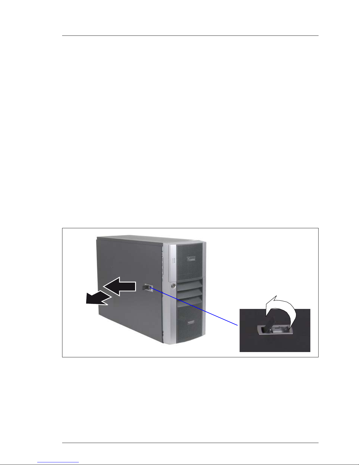
Figure 2: Opening the server
Ê Open the latch (1).
The opening of the latch pushes back the side cover (2) and disengages the
hooks on the top of the side cover.
Ê Remove the side cover (3).
1
2
3
Page 22
22 Options Guide TX200 S4
Rack model Preparation
4.2 Rack model
Ê Terminate all applications and shut down the server correctly.
Ê If your operating system has not switched off the server, press the on/off
button.
Ê Pull all power connectors out of the power outlets.
4.2.1 Opening the server
Pulling the server out of the rack and opening the server
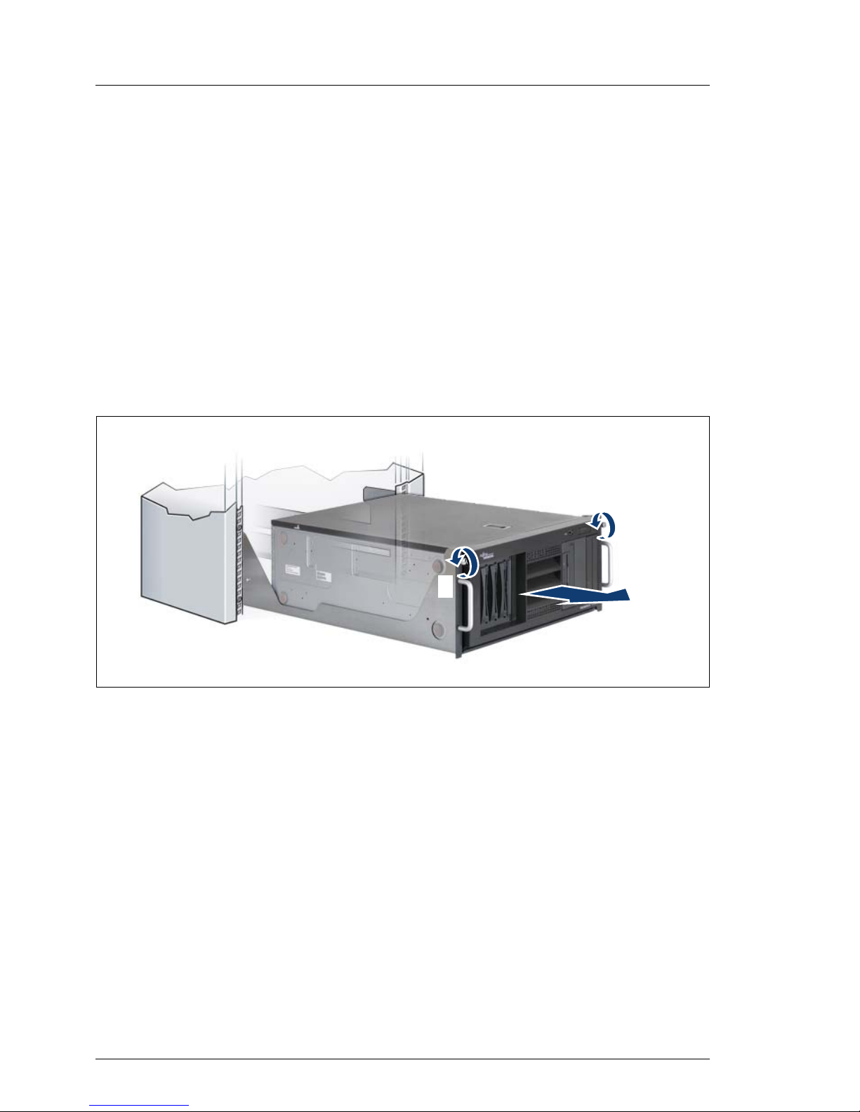
Figure 3: Loosening the knurled screws
Ê Loosen the two knurled screws (1) and pull the server as far as possible out
of the rack (2).
Ê Open the latch.
Ê Remove the top cover.
Removing the server from the rack and opening the server
Depending on how accessible the server is in the rack cabinet, it can make
sense to remove the server from the rack cabinet:
Ê Disconnect all cables on the rear side of the server.
1
2
1
Page 23
TX200 S4 Options Guide 23
Preparation Rack model
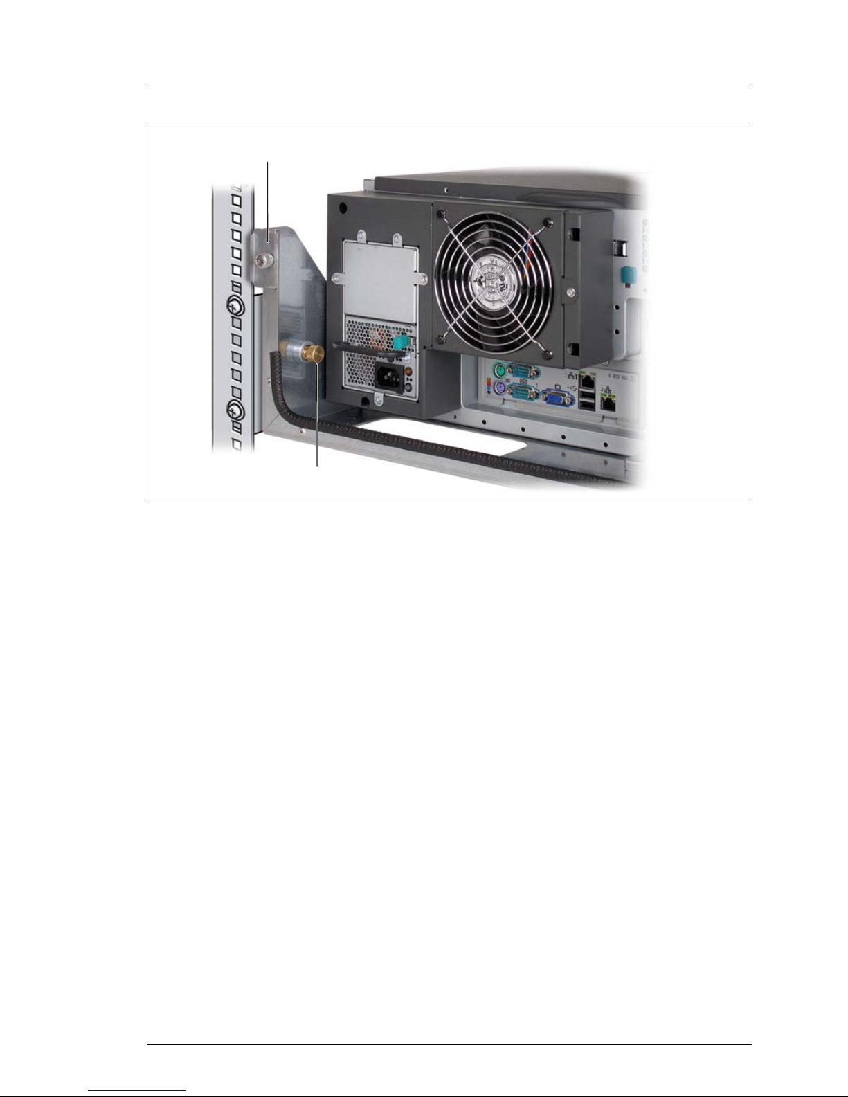
Figure 4: Loosening the screws in the rack cabinet
Ê Loosen the screws (1+2) on the left and the right side at the rear side.
V CAUTION!
At least two people are needed to lift the server out of the rack cabinet.
Ê Loosen the two knurled screws at the front side (see the figure 3 on
page 22) and pull the server carefully out of the rack.
V CAUTION!
If you pull out the server too far, the server will fall down.
Ê Lift the server out of the rails and place it on a table, for example.
Ê Open the latch.
Ê Remove the top cover.
1
2
Page 24
24 Options Guide TX200 S4
System fans and traverse Preparation
4.3 System fans and traverse
4.3.1 Removing the system fan 1
Figure 5: Removing the system fan 1
Ê Disconnect the fan cable from the connector FAN1 SYS on the system
board.
Ê Push the lock (1) in direction of the arrow until it disengages.
Ê Push the air duct to the front side (2) until the pins on the PSU casing and
the traverse disengage.
Ê Remove the air duct with the integrated system fan 1.
2
1
Page 25

TX200 S4 Options Guide 25
Preparation System fans and traverse
4.3.2 Removing the system fan 2
Figure 6: Removing the system fan 2
Ê Disconnect the fan cable from the connector FAN2 SYS on the system
board.
Ê Pull the lock upward (1) and swivel the system fan 2 forward (2).
Ê Take out the system fan 2 downward.
4.3.3 Removing the traverse with the air duct over the
main memory
Ê Remove the system fan 1 and system fan 2.
Figure 7: Removing the traverse
Ê Push the lock (1) and pull out the traverse sideward (2).
1
2
2
1
Page 26
26 Options Guide TX200 S4
System fans and traverse Preparation
Ê Unhook the traverse at the left side (see circles).
Ê Take the traverse with the memory air duct carefully out of the housing.
4.3.4 Removing the system fan 3
Ê Remove the system fan 1, system fan 2 and the traverse.
Figure 8: Removing the system fan 3
Ê Disconnect the fan cable from the connector FAN3 SYS on the system
board.
Ê Pull the lock (1) inward.
Ê Pull the system fan 3 forward (2) to disengage the four snap-fits (see circles).
Ê Remove the system fan 3 sideward.
2
1
Page 27
TX200 S4 Options Guide 27
5Main memory
V CAUTION!
Observe the safety instructions in the chapter “Safety notes” on
page 15ff.
The system board supports up to 24 Gbytes of main memory. 6 slots (2 slots
form a memory bank) are provided for the main memory. Each memory bank is
equipped with two 512 Mbyte, 1 Gbyte, 2 Gbyte or 4 Gbyte FBD667/PC2-5300F
Fully Buffered DIMM memory modules.
As memory bank 1 is already equipped either with 1 Gbyte, 2 Gbyte, 4 Gbyte or
8 Gbyte of memory in the basic unit, the memory extensions can be performed
up to two times for memory banks 2 and 3.
ECC with memory scrubbing and with the Single Device Data Correction
(SDDC, Chipkill) function is standard.
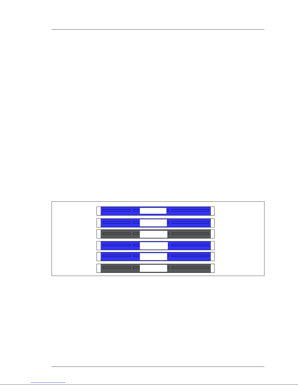
5.1 Equipping rules
Figure 9: Structure of the main memory in memory banks and memory modules
– The memory modules have to be based on x4 or x8 organised single or dual
ranked FDB667/PC2-5300 fully buffered DIMM modules and must be
populated in pairs. It is only allowed you use memory modules released by
Fujitsu Siemens Computers.
– Each pair must consist of identical memory modules.
DIMM-3B
DIMM-2B
DIMM-1B
DIMM-3A
DIMM-2A
DIMM-1A
Page 28
28 Options Guide TX200 S4
Extending/replacing the main memory Main memory
– The module capacity between pairs can differ: pair 1A/1B can be populated
with two 512 Mbyte modules and pair 2A/2B with two 1 Gbyte modules.
The table below shows the order in which the memory banks must be equipped:
5.2 Extending/replacing the main memory
Ê Open the server, remove the system fan 1, the system fan 2 and the traverse
as described in the chapter “Preparation” on page 21ff.
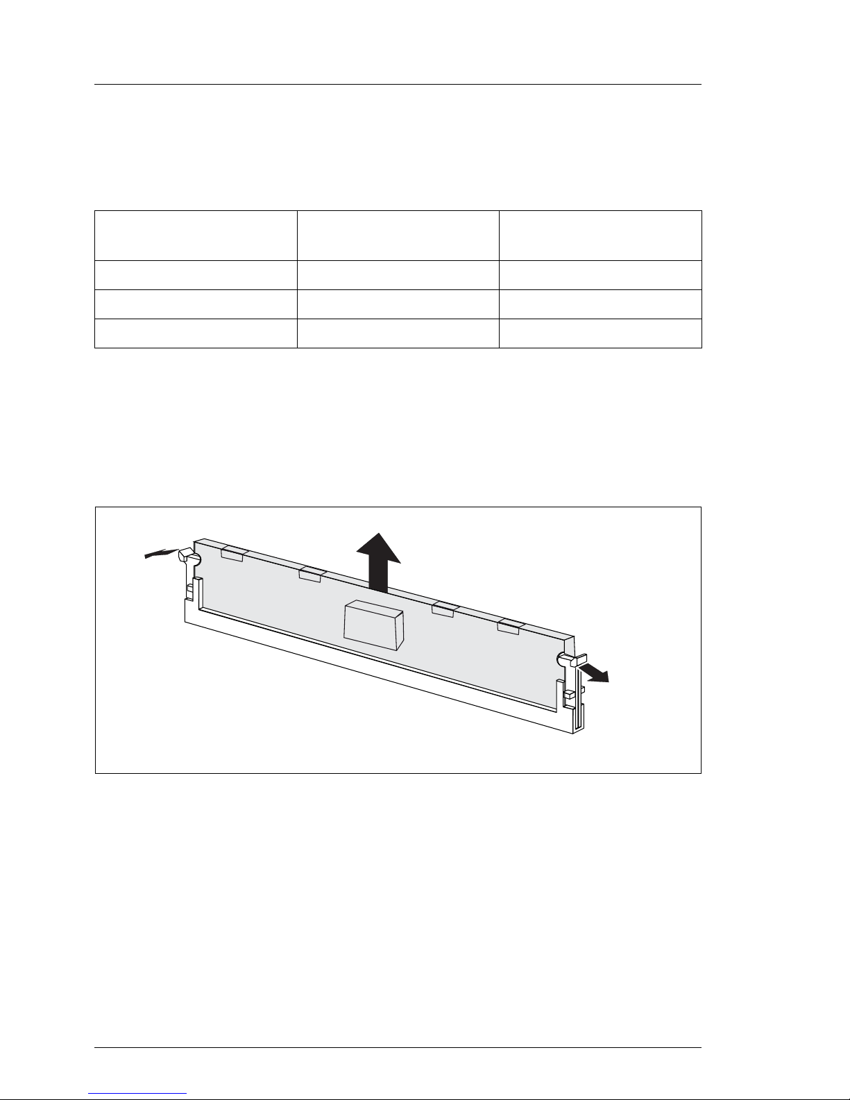
Figure 10: Removing a memory module
Ê Press the holders on either side of the mounting location concerned outward
(1).
Ê If the mounting location was already equipped: pull the memory module out
of the mounting location (2).
module pair 1A/1B
(black)
module pair 2A/2B
(blue)
module pair 3A/3B
(blue)
populated empty empty
populated populated empty
populated populated populated
1
1
2
Page 29
TX200 S4 Options Guide 29
Main memory Extending/replacing the main memory
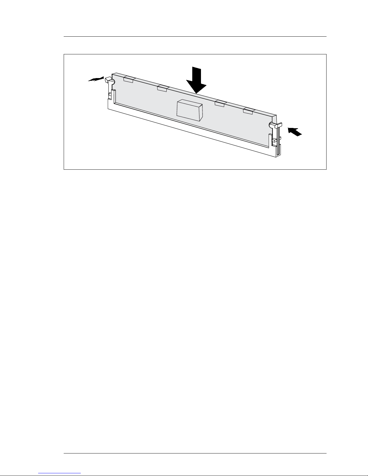
Figure 11: Inserting a memory module
Ê Press the holders on either side of the mounting location concerned
outward.
Ê Insert the memory module in the mounting location (1) until the holders at
the sides engage (2).
Ê Reinsert the traverse, the system fan 1 and system fan 2 as described in the
chapter “Completion” on page 85ff.
Ê Close the server, connect it to the power outlet, and switch it on as described
in the chapter “Completion” on page 85ff.
2
2
1
Page 30

Page 31

TX200 S4 Options Guide 31
6 Processors
V CAUTION!
Observe the safety instructions in the chapter “Safety notes” on
page 15ff.
V CAUTION!
Processors are modules which can react extremely sensitively to electrostatic discharges and which must therefore always be handled with care.
After a processor has been removed from its protective sleeve or from its
socket, place it with its smooth side down on a non-conducting, antistatic
surface. Never push a processor over a surface.
6.1 Installing a second processor
The system board can be upgraded with a second processor. The upgrade kit
consists of a processor and a heat sink.
V CAUTION!
Only processors of the same type may be used on the system board. The
second processor must have at least the same clock frequency as the
first processor. If the two processors have different clock frequencies,
they both will operate with the lower clock frequency.
For dual operation, use a suitable multiprocessor operating system.
Ê Open the server, remove the system fan 1, the system fan 2 and the traverse
as described in the chapter “Preparation” on page 21ff.
Page 32

32 Options Guide TX200 S4
Installing a second processor Processors
Installing the processor and the heat sink
Figure 12: Releasing the lever
Ê Release the socket lifter by pressing it sideways and pull it upward as far as
it will go (1).
Ê Open the cover (2).
Figure 13: Inserting the processor
Ê Position the new processor over the socket and then carefully press it into
the socket (1).
V CAUTION!
The processor can only be installed in one particular direction. Note
the marking on one of the corners. To avoid damaging the processor,
do not force it into the socket.
Ê Close the cover (2).
Ê Remove the plastic cover (3).
1
2
1
2
4
3
Page 33

TX200 S4 Options Guide 33
Processors Installing a second processor
Ê Lock the processor in place in the socket by returning the socket lifter to its
original position (4).
Figure 14: Removing the protective cover
Ê Remove the protective cover on the underside of the heat sink.
Page 34

34 Options Guide TX200 S4
Installing a second processor Processors
Figure 15: Installing the heat sink
Ê Place the heat sink on the processor socket.
Ê Fasten the heat sink by tightening the four screws in a crossover pattern.
V CAUTION!
Never install a processor without a heat sink and processor fan as
otherwise the processor may overheat, causing the processor and
system board to fail.
Ê Reinsert the traverse, the system fan 1 and system fan 2 as described in the
chapter “Completion” on page 85ff.
Ê Close the server, connect it to the power outlet, and switch it on as described
in the chapter “Completion” on page 85ff.
Page 35

TX200 S4 Options Guide 35
Processors Replacing the processor
6.2 Replacing the processor
V CAUTION!
Only processors of the same type may be used on the system board. The
second processor must have at least the same clock frequency as the
first processor. If the two processors have different clock frequencies,
they both will operate with the lower clock frequency.
For dual operation, use a suitable multiprocessor operating system.
Ê Open the server, remove the system fan 1, the system fan 2 and the traverse
as described in the chapter “Preparation” on page 21ff.
Ê Loosen the four screws of the heat sink in a crossover pattern.
Ê Loosen the heat sink by turning it back and forth and then lift it out.
Ê Remove the residual thermal paste from the underside of the heat sink.
Ê Clean the underside of the heat sink using a lint-free cloth.
Figure 16: Removing an old processor
Ê Release the socket lifter by pressing it sideways and pull it upward as far as
it will go (1).
Ê Open the cover (2).
Ê Lift the installed processor carefully out of the socket (3).
1
2
3
Page 36

36 Options Guide TX200 S4
Replacing the processor Processors
Figure 17: Inserting a new processor
Ê Position the new processor over the socket and thenplace it carefully into the
socket (1).
V CAUTION!
The processor can only be installed in one particular direction. Note
the marking on one of the corners. To avoid damaging the processor,
do not force it into the socket.
Ê Close the cover (2).
Ê Lock the processor in place in the socket by returning the socket lifter to its
original position (3).
Ê Apply a small amount of thermal paste to the upper side of the new
processor.
Ê Ensure a thin and even distribution of the thermal paste.
Ê Place the heat sink on the processor socket (see page 34).
Ê Fasten the heat sink by tightening the four screws in a crossover pattern.
Ê Reinsert the traverse, the system fan 1 and system fan 2 as described in the
chapter “Completion” on page 85ff.
Ê Close the server, connect it to the power outlet, and switch it on as described
in the chapter “Completion” on page 85ff.
1
2
3
Page 37

TX200 S4 Options Guide 37
Processors Replacing the heat sin
k
6.3 Replacing the heat sink
Ê Open the server, remove the system fan 1, the system fan 2 and the traverse
as described in the chapter “Preparation” on page 21ff.
Ê Loosen the four screws of the heat sink socket in a crossover pattern.
Ê Loosen the heat sink by turning it back and forth and then lift it out.
Ê Clean the upper side of the processor using a lint-free cloth.
Ê Remove the protective cover from the new heat sink (see page 33).
Ê Place the heat sink on the processor socket (see page 34).
Ê Fasten the heat sink by tightening the four screws in a crossover pattern.
Ê Reinsert the traverse, the system fan 1 and system fan 2 as described in the
chapter “Completion” on page 85ff.
Ê Close the server, connect it to the power outlet, and switch it on as described
in the chapter “Completion” on page 85ff.
Page 38

Page 39

TX200 S4 Options Guide 39
7 Accessible drives and LSP
V CAUTION!
Observe the safety instructions in the chapter “Safety notes” on
page 15ff.
Three 5.25-inch bays are available for accessible drives. In these bays you can
install DVD/DVD-RW drives, magnetic tape drives, a multibay (slimline DVD and
FDD/ServerView Local Service Panel) or a hard disks extension box.
7.1 Installing an accessible 5.25-inch drive
The 5.25-inch drives available are magnetic tape drives and DVD-ROM burners.
These drives can be installed in the free 5.25-inch bays.
Ê Open the server as described in the chapter “Preparation” on page 21ff.
I If you install a magnetic tape drive with double height (3.2-inch), two
dummy modules of the free 5.25-inch bays must be removed.
Figure 18: Removing the screws of the dummy module
Ê Remove the two screws (see the circles).
Page 40

40 Options Guide TX200 S4
Installing an accessible 5.25-inch drive Accessible drives and LSP
Figure 19: Removing the dummy module
Ê Push the dummy module out of the bay frontward.
V CAUTION!
Keep the dummy module for future use. If you remove the accessible
drive again and do not replace it with a new one, the dummy module must
be reinstalled to comply with EMC regulations and to satisfy cooling
requirements and fire protection measures.
Ê Push the new drive about halfway into the bay.
Ê Connect the data cable to the accessible drive (see the cabling plans in the
Appendix).
Ê Connect the power cable to the accessible drive (see the cabling plans in the
Appendix).
Ê Push the drive fully into the bay and fasten it with two screws.
Page 41

TX200 S4 Options Guide 41
Accessible drives and LSP Installing an accessible 5.25-inch drive
Figure 20: Example cabling CD drive
Ê Connect the data cable to the system board (see the cabling plans in the
Appendix).
Ê Close the server, connect it to the power outlet, and switch it on as described
in the chapter “Completion” on page 85ff.
Page 42

42 Options Guide TX200 S4
Installing the multibay Accessible drives and LSP
7.2 Installing the multibay
Ê Open the server as described in the chapter “Preparation” on page 21ff.
Ê Remove the dummy module from a 5.25-inch bay for accessible drives:
Ê Remove the two screws.
Ê Push the dummy module out of the bay frontward.
V CAUTION!
Keep the dummy module for future use. If you remove the multibay
again and do not replace it with new drives, the dummy module must
be reinstalled to comply with EMC regulations and to satisfy cooling
requirements and fire protection measures.
Figure 21: Pushing the floppy drive in the multibay
Ê Push the floppy drive in the multibay and fasten it with two screws on each
side.
I You can install a LSP (ServerView Local Service Panel) instead of the
floppy drive (see section “Installing a LSP in the multibay” on
page 46).
Page 43

TX200 S4 Options Guide 43
Accessible drives and LSP Installing the multibay
Figure 22: Removing the slimline dummy module
Ê Pull up the green touch point.
Ê Pull out the slimline dummy module frontward.
Figure 23: Removing the slimline frame
Ê Expand the frame sideward.
Page 44

44 Options Guide TX200 S4
Installing the multibay Accessible drives and LSP
Figure 24: Inserting the slimline drive in the frame
Ê Insert the slimline drive in the frame: the four noses fasten the drive to the
frame.
Ê Push the slimline drive with its frame in the bay of the multibay until it
engages.
Figure 25: Cabling of the slimline drive
Ê Connect the PS adapter cable to the slimline drive (see the cabling plans in
the Appendix).
Ê Connect the SATA cable to the slimline drive (see the cabling plans in the
Appendix).
Page 45

TX200 S4 Options Guide 45
Accessible drives and LSP Installing the multibay
Figure 26: Installing the multibay
Ê Push the multibay with its cables in the lower bay until the holes fit to the
threads.
Ê Fasten the multibay with two screws (see the circles).
Ê Connect the PS adapter cable of the slimline drive to a power plug (see the
cabling plans in the Appendix).
Ê Connect a power plug to the floppy drive (see the cabling plans in the
Appendix).
Ê Connect the floppy cable to the floppy drive and to the connector Floppy on
the system board (see the cabling plans in the Appendix).
Ê Connect the SATA cable of the slimline drive to the system board (see the
cabling plans in the Appendix).
Ê Close the server, connect it to the power outlet, and switch it on as described
in the chapter “Completion” on page 85ff.
Page 46

46 Options Guide TX200 S4
Installing the multibay Accessible drives and LSP
7.2.1 Installing a LSP in the multibay
Figure 27: LSP frame
Figure 28: Inserting a LSP in the frame
Ê Push the LSP in the frame until it engages in the upper recess (see the
circle).
Page 47

TX200 S4 Options Guide 47
Accessible drives and LSP Installing the multibay
Figure 29: Inserting a LSP in the multibay
Ê Push the frame in multibay from the rear side and fasten the frame with two
screws on each side.
Figure 30: Cabling the LSP
Ê After installing the multibay in the server: connect the free plug of the I2C
cable to the LSP.
Page 48

48 Options Guide TX200 S4
Installing the hard disks extension box Accessible drives and LSP
7.3 Installing the hard disks extension box
Two 5.25-inch bays for accessible drives can be used to install a hard disks
extension box.
Two variants of the hard disks extension box are available:
– Variant 1:
one bay for a ServerView Local Service Panel, one bay for a slimline DVD
drive and two bays for 3.5“ hard disks
– Variant 2 (special release required):
eight bays for 2.5“ hard disks
Ê Open the server as described in the chapter “Preparation” on page 21ff.
Ê Remove the dummy modules from two 5.25-inch bays for accessible drives:
Ê Remove the two screws.
Ê Push the dummy module out of the bay frontward.
V CAUTION!
Keep the dummy modules for future use. If you remove the hard disks
extension box again and do not replace it with new drives, the dummy
modules must be reinstalled to comply with EMC regulations and to
satisfy cooling requirements and fire protection measures.
Page 49

TX200 S4 Options Guide 49
Accessible drives and LSP Installing the hard disks extension box
Removing and pushing inward of the metal brackets
The upper drives lay on four metal brackets. You have to remove and push
inward the four metal brackets before it is possible to insert the hard disks
extension box.
Figure 31: Removing the metal brackets - first step
Ê Break the two metal brackets out of the housing using a screws driver.
V CAUTION!
The sharp cant may hurt you!
Page 50

50 Options Guide TX200 S4
Installing the hard disks extension box Accessible drives and LSP
Figure 32: Removing the metal brackets - second step
Figure 33: Removing the metal brackets - third step
Ê Turn the two metal brackets around until they break out.
Page 51

TX200 S4 Options Guide 51
Accessible drives and LSP Installing the hard disks extension box
Figure 34: Pushing inward the metal brackets - first step
Ê Break through the pointy sides of the two inner metal brackets using a
screws driver.
Figure 35: Pushing inward the metal brackets - second step
Ê Push the metal brackets inward until they cannot blockade the interior space
of the bay.
Page 52

52 Options Guide TX200 S4
Installing the hard disks extension box Accessible drives and LSP
3.5“ hard disks extension box
Ê Remove and push the metal brackets inward before.
Figure 36: Installing 3.5“ hard disks extension box
Ê Push the hard disks extension box fully into the bay and fasten it with four
screws.
Figure 37: Example connecting the power cable
Ê Connect the power cable to the hard disks extension box (see the cabling
plans in the Appendix).
Page 53

TX200 S4 Options Guide 53
Accessible drives and LSP Installing the hard disks extension box
Figure 38: Example connecting the SATA cable
Ê Connect the SATA cable to the hard disks extension box and the second port
of a controller (see the cabling plans in the Appendix).
I It is possible to install a slimline drive in the hard disks extension box. The
procedure is the same as for installing the slimline drive in the multibay.
I It is possible to install a LSP in the hard disks extension box. In this case
you can push the LSP in the top bay of the hard disks extension box
without using a frame.
Ê Close the server, connect it to the power outlet, and switch it on as described
in the chapter “Completion” on page 85ff.
Page 54

54 Options Guide TX200 S4
Installing the hard disks extension box Accessible drives and LSP
2.5“ hard disks extension box
Ê Push the metal brackets inward until they cannot blockade the interior space
of the bay.
Figure 39: Installing 2.5“ hard disks extension box
Ê Push the hard disks extension box fully into the bay and fasten it with three
screws.
Figure 40: Example connecting the SATA cables to the controller
Ê Connect the SATA cable to the hard disks extension box and the second port
of a controller (see the cabling plans in the Appendix).
Page 55

TX200 S4 Options Guide 55
Accessible drives and LSP Installing the hard disks extension box
Figure 41: Example connecting the PS and SAS cables
Ê Connect the power cables and the SAS cables to the hard disks extension
box (see the cabling plans in the Appendix).
Ê Close the server, connect it to the power outlet, and switch it on as described
in the chapter “Completion” on page 85ff.
Page 56

Page 57

TX200 S4 Options Guide 57
8 Expansion boards in the PCI slots
V CAUTION!
Observe the safety instructions in the chapter “Safety notes” on
page 15ff.
The system board offers seven PCI slots:
– 2 x PCI-X slots(64 bit / 133 MHz IOOP
TM
)
– 4 x PCI-Express slots, Gen1, mechanical PCIe x8
– 1 x PCI slot 32 bit / 33 MHz)
The hardware of the system board optimizes the speed of the PCI bus (IOOP™)
for PCI slots 4 and 5, depending on how the slots are equipped. If only one of
this two slots is occupied, the PCI bus speed is 133 MHz. If both slots are
occupied, the PCI bus speed is 100 MHz.
Performance Adapter SNR: S26361-D2504:
The Performance Adapter combines two PCIe x4 slots to one PCIe x8 slot. If
the adapter has been installed in slot 2 (or 7), slot 1 (or 6) can be operated as
PCIe x8.
Page 58

58 Options Guide TX200 S4
Installing an expansion board Expansion boards in the PCI slots
8.1 Installing an expansion board
Ê Open the server as described in the chapter “Preparation” on page 21ff.
Ê Remove the system fan 2 as described in the section “Removing the system
fan 2” on page 25.
Figure 42: Loosening the locking levers
Ê Press on the two green locking levers in the direction of the arrow and push
the locking levers out of the housing.
Page 59

TX200 S4 Options Guide 59
Expansion boards in the PCI slots Installing an expansion board
Figure 43: Opening the slot locking bar
Ê Open the slot locking bar.
Page 60

60 Options Guide TX200 S4
Installing an expansion board Expansion boards in the PCI slots
Figure 44: Removing the slot cover
Ê Remove the PCI slot cover.
V CAUTION!
Keep the slot cover for further use. If the expansion board is removed
again and not replaced with a new one, the slot cover has to be
reinstalled to comply with applicable EMC regulations and satisfy
cooling requirements and fire protection measures.
Ê Unpack the new expansion board, and make the desired settings. You
should read the accompanying documentation supplied with the expansion
board beforehand.
Ê Install the expansion board into the PCI slot and press it carefully into the
associated plug-in location on the system board until it engages properly.
Ê Close the slot locking bar and press on the two green locking levers at the
server’s rear side until they engage.
Ê If required, connect the cables to the expansion board and other compo-
nents.
Page 61

TX200 S4 Options Guide 61
Expansion boards in the PCI slots Installing a BBU
Ê Install the system fan 2 as described in the section “Installing the system fan
2” on page 86.
Ê Close the server, connect it to the power outlet, and switch it on as described
in the chapter “Completion” on page 85ff.
8.2 Installing a BBU
You can install up to two Battery Backup Units (BBU).
Ê Open the server as described in the chapter “Preparation” on page 21ff.
Ê Remove the system fan 1, the system fan 2 and the traverse as described in
the section “System fans and traverse” on page 24ff.
Figure 45: Connecting the cable to the BBU
Ê Connect the cable to the BBU and the expansion board.
V CAUTION!
Make sure that the connector side with two pin rows is on the top.
Otherwise you risk short-circuits.
Page 62

62 Options Guide TX200 S4
Installing a BBU Expansion boards in the PCI slots
Ê Install the expansion board.
Figure 46: Inserting the BBU
Ê Push the BBU in the housing.
Side with one pin row: Side with two pin rows:
Page 63

TX200 S4 Options Guide 63
Expansion boards in the PCI slots Installing a BBU
Figure 47: Position screws
Ê Fasten the BBU with three screws at the outer side (the first BBU in the front
range, a second BBU in the middle range).
Ê Install the traverse, the system fan 2 and the system fan 1 as described in
the section “System fans and traverse” on page 85ff.
Ê Close the server, connect it to the power outlet, and switch it on as described
in the chapter “Completion” on page 85ff.
BBU 1
BBU 2
Page 64

64 Options Guide TX200 S4
Installing the Performance Adapter Expansion boards in the PCI slots
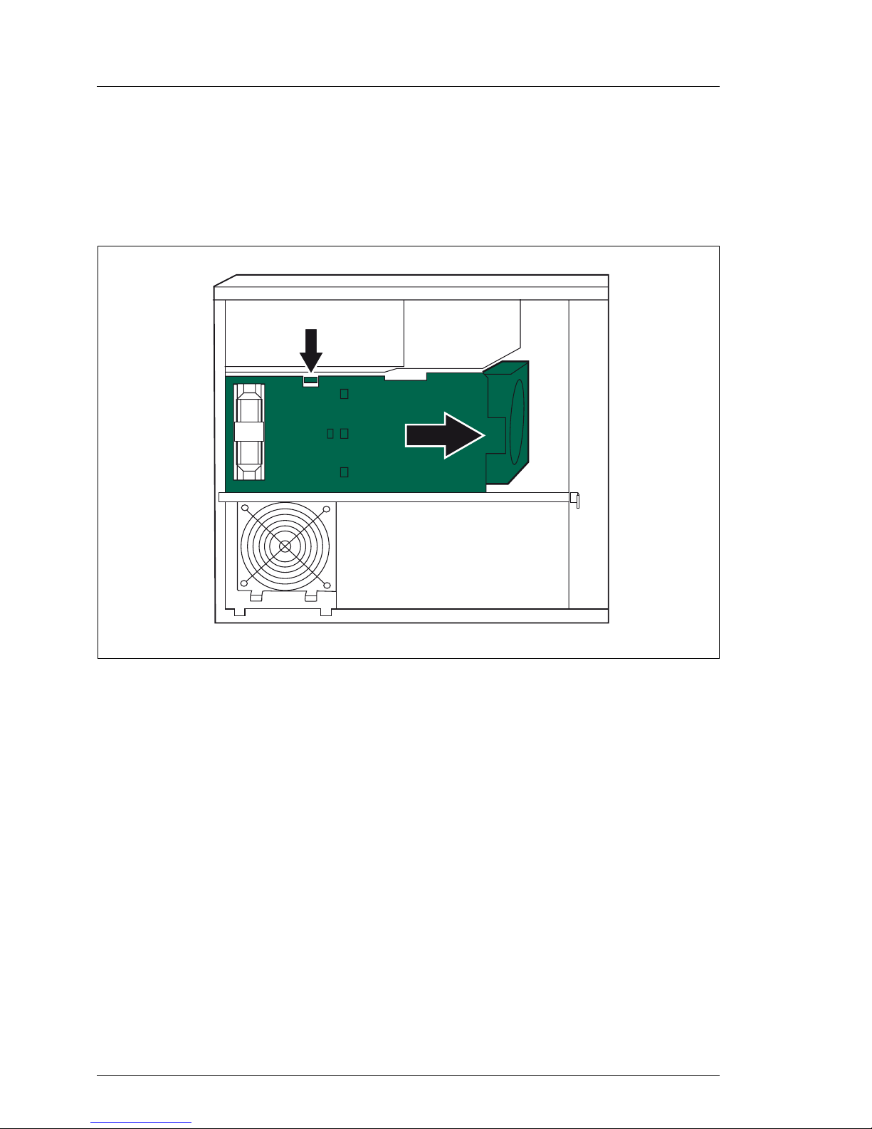
8.3 Installing the Performance Adapter
Ê Open the server as described in the chapter “Preparation” on page 21ff.
Ê Remove the system fan 1and the system fan 2 as described in the section
“System fans and traverse” on page 24ff.
Figure 48: Performance Adapter in slot 7
Ê Insert the Performance Adapter in slot 2 or slot 7.
Ê Install the system fan 2 and the system fan 1 as described in the section
“System fans and traverse” on page 85ff.
Ê Close the server, connect it to the power outlet, and switch it on as described
in the chapter “Completion” on page 85ff.
Page 65

TX200 S4 Options Guide 65
9 SATA SW RAID
V CAUTION!
Observe the safety instructions in the chapter “Safety notes” on
page 15ff.
The SATA SW RAID 5 functionality will be activated by installing a license key
(RAID key).
9.1 Inserting the RAID key
Ê Open the server as described in the chapter “Preparation” on page 21ff.
Ê Remove the system fan 2 as described in the section “Removing the system
fan 2” on page 25.
Figure 49: Inserting the RAID key
Ê Insert the RAID key in the round socket on the system board.
Ê Install the system fan 2 as described in the section “Installing the system fan
2” on page 86.
Ê Close the server, connect it to the power outlet, and switch it on as described
in the chapter “Completion” on page 85ff.
Page 66

Page 67

TX200 S4 Options Guide 67
10 Parallel interface for printers
V CAUTION!
Observe the safety instructions in the chapter “Safety notes” on
page 15ff.
10.1 Installing a parallel interface
Ê Open the server as described in the chapter “Preparation” on page 21ff.
Ê Remove the system fan 1, the system fan 2 and the traverse as described in
the section “System fans and traverse” on page 24ff.
Ê Install the parallel interface as described in the section “Installing an
expansion board” on page 58ff.
Figure 50: Routing the cable
Ê Route the cable as shown in the photo.
Ê Connect the cable’s connector to the parallel port connector on the system
board.
Page 68

68 Options Guide TX200 S4
Installing a parallel interface Parallel interface for printers
Ê Install the traverse, the system fan 2 and the system fan 1 as described in
the section “System fans and traverse” on page 85ff.
Ê Close the server, connect it to the power outlet, and switch it on as described
in the chapter “Completion” on page 85ff.
Page 69

TX200 S4 Options Guide 69
11 Conversion to hot-plug PS and
redundant system fans
V CAUTION!
Observe the safety instructions in the chapter “Safety notes” on
page 15ff.
Ê Open the server as described in the chapter “Preparation” on page 21ff.
Ê Remove the system fan 1, the system fan 2 and the traverse as described in
the section “System fans and traverse” on page 24ff.
Figure 51: Removing the power cables
Ê Disconnect all power cables from the system board and the drives (see the
cabling plans in the Appendix).
Ê Thread the power cables through the openings.
Page 70

70 Options Guide TX200 S4
Conversion to hot-plug PS/redundant system fans
Figure 52: Removing the PSU
Ê Remove the four screws and pull the power supply unit inward and take it out
of the server.
Figure 53: Removing the adapter metal cover
Ê Remove the six screws and push the adapter metal cover inward in a slight
angle and take it out of the server.
Page 71

TX200 S4 Options Guide 71
Conversion to hot-plug PS/redundant system fans
Figure 54: Installing the Power backplane in the PS cage
Ê Insert the Power backplane in the PS cage.
Ê Push the Power backplane in direction of the arrow until it engages in the
guidances of the PS cage.
Ê Fasten the Power backplane with one screw (see circle).
Page 72

72 Options Guide TX200 S4
Conversion to hot-plug PS/redundant system fans
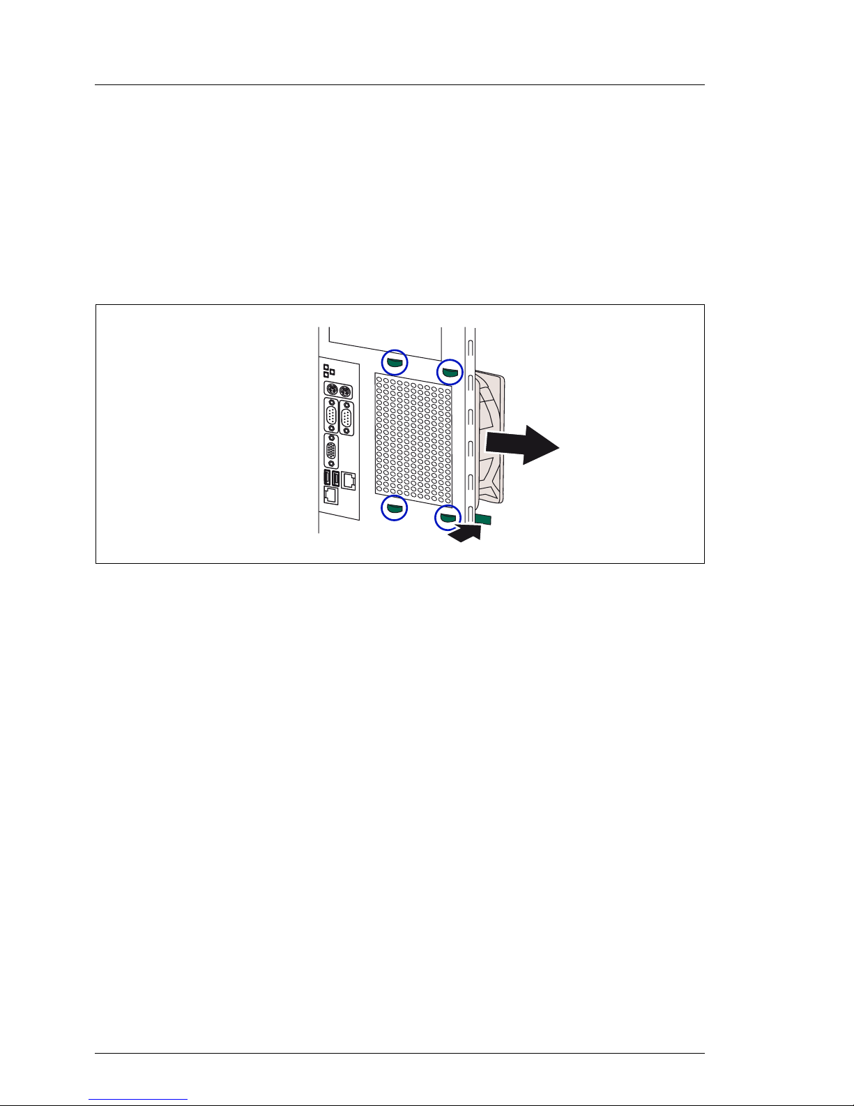
Figure 55: Breaking out the pre-cut plate
Ê Break out the pre-cut plate for the plug of the redundant fan using a screws
driver.
Figure 56: Inserting the redundant fan
Ê Insert the redundant fan with its holder in the four recesses at the rear side
of the housing.
Page 73

TX200 S4 Options Guide 73
Conversion to hot-plug PS/redundant system fans
Figure 57: Fastening the holder
Ê Push the holder to the left side until the four hooks engage.
Ê Fasten the holder with three screws.
Page 74

74 Options Guide TX200 S4
Conversion to hot-plug PS/redundant system fans
Figure 58: Installing the PS cage
Ê Push the PS cage from the rear side into the housing. In the floorstand
model the Power backplane is positioned under the top cover, and in the rack
model at the right-hand side cover (seen from front side).
V CAUTION!
Make sure that the noses of the PS cage engage in the housing (see
circles).
Page 75

TX200 S4 Options Guide 75
Conversion to hot-plug PS/redundant system fans
Figure 59: Fastening the PS cage
Ê Fasten the PS cage with three screws.
Figure 60: Cabling of the redundant fan
Ê Connect the cable T26139-Y3908-V101 to the system board connector
Fan4 SYS and to the fan connector (see the cabling plans in the Appendix).
Page 76

76 Options Guide TX200 S4
Conversion to hot-plug PS/redundant system fans
Figure 61: PS cabling - step 1
Ê Thread the power cable T26139-Y3758-V5 through the recess.
Ê Connect the power cable to the connector X3 on the Power backplane.
Ê Connect the power cable to the connector PWR1 on the system board.
Page 77

TX200 S4 Options Guide 77
Conversion to hot-plug PS/redundant system fans
Figure 62: PS cabling - step 2
Ê Thread the power cable T26139-Y3952-V2 through the recess.
Ê Connect the power cable to the connector X4 on the Power backplane.
Ê Connect the power cable to the connectors PWR3, PWR2 and PC98 on the
system board.
Page 78

78 Options Guide TX200 S4
Conversion to hot-plug PS/redundant system fans
Figure 63: PS cabling - step 3
Ê Thread the power cable T26139-Y3952-V101 through the recess.
Ê Connect the power cable to the connector X5 on the Power backplane.
Ê Connect the plugs of the power cable to the drives and the HDD backplanes
(see the cabling plans in the Appendix).
Page 79

TX200 S4 Options Guide 79
Conversion to hot-plug PS/redundant system fans
Figure 64: Installing the PS safe guard
Ê Install the PS safe guard and fasten it with one screw.
Ê Push the both power supply modules in the bays of PS cage until they
engage (description see the operating manual).
Ê Install the traverse, the system fan 2 and the system fan 1 as described in
the section “System fans and traverse” on page 85ff.
Ê Close the server, connect it to the power outlet, and switch it on as described
in the chapter “Completion” on page 85ff.
Page 80

Page 81

TX200 S4 Options Guide 81
12 Converting from the floorstand
model to the rack model
V CAUTION!
Observe the safety instructions in the chapter “Safety notes” on
page 15ff.
Figure 65: Removing the stabilizer
Ê Remove the two screws.
Ê Lift the server somewhat and remove the stabilizer.
I The stabilizer is no longer required.
Ê Open the server as described in the chapter “Preparation” on page 21ff.
Page 82

82 Options Guide TX200 S4
Converting from the floorstand model to the rack model
Figure 66: Removing the front cover
Ê Release the three locks and open the front cover.
Ê Unhook the front cover at the other side and remove the front cover.
I The front cover is no longer required.
Ê Lay the server on its right-hand side. Get a second person to help you do
this. The server can weigh up to 35 kg.
Page 83

TX200 S4 Options Guide 83
Converting from the floorstand model to the rack model
Figure 67: Position of the recesses
Ê Press the three hooks of the plastic front cover on the bottom side in the
recesses (see the circles) of the housing.
Ê Press the plastic front cover onto the housing until the three tabs on the top
side (see the circles) engage.
Figure 68: Installed plastic front cover
Ê Close the server as described in the chapter “Completion” on page 85ff.
Page 84

84 Options Guide TX200 S4
Converting from the floorstand model to the rack model
Ê Install the rack model in the rack as described in the operating manual.
To enable the rack model to be presented correctly in ServerView, proceed as
follows:
Ê Place the ServerStart CD-ROM CD1 in the drive.
Ê Select “Tools - System Configuration Utilities - SCU Chassis Model
Conversion“ and convert the server type to rack mounted.
Page 85

TX200 S4 Options Guide 85
13 Completion
V CAUTION!
Observe the safety instructions in the chapter “Safety notes” on
page 15ff.
13.1 System fans and traverse
13.1.1 Installing the system fan 3
Figure 69: Installing the system fan 3
Ê Put the hooks of the system fan 3 into the recesses on the server’s rear side
(see circles).
Ê Push the system fan 3 in direction to the connector panel until the lock
engages.
Ê Connect the fan cable to the connector FAN3 SYS on the system board.
Page 86

86 Options Guide TX200 S4
System fans and traverse Completion
13.1.2 Installing the traverse with the air duct over the
main memory
Ê Install the system fan 3 before.
Figure 70: Installing the traverse
Ê Insert carefully the traverse with the air duct over the main memory.
Ê Hook the traverse into the left side (see circles).
Ê Press on the traverse at the right side (see arrow) until the lock engages.
13.1.3 Installing the system fan 2
Ê Install the system fan 3 and the traverse before.
Figure 71: Installing the system fan 2
Ê Hook the system fan into the traverse (see circles) and press it in the housing
until it clicks into place.
1
2
Page 87

TX200 S4 Options Guide 87
Completion System fans and traverse
Ê Connect the fan cable to the connector FAN2 SYS on the system board.
13.1.4 Installing the system fan 1
Ê Install the system fan 3, the traverse and the system fan 2 before.
Figure 72: Installing the system fan 1
Ê Connect the fan cable to the connector FAN1 SYS on the system board.
Ê Insert carefully the air duct with the integrated system fan 1 using the pins
on the PSU casing and the traverse (see circles).
Ê Push the air duct to the rear side until the pins on the PSU casing and the
traverse engage. Make sure that the lock engages too.
Page 88

88 Options Guide TX200 S4
Floorstand model Completion
13.2 Floorstand model
13.2.1 Closing the server
Ê Open the latch.
Figure 73: Attaching the left-hand side cover
Ê Position the left-hand side cover in the five recesses (see circles) of the
housing (1).
Ê Push the left-hand side cover against the housing and push down the latch
(2).
Closing the latch pushes the left-hand side cover to the front side and the
hooks on the upper cant of the left-hand side cover engage.
Ê Insert the key.
Ê Lock the server.
Ê Connect all power plugs to the power outlets.
Ê Press the on/off key to start up the server.
2
1
Page 89

TX200 S4 Options Guide 89
Completion Rack model
13.3 Rack model
13.3.1 Closing the server
Ê Open the latch.
Ê Position the top cover in the five recesses of the housing.
Ê Push the top cover against the housing and push down the latch.
Closing the latch pushes the top cover to the front side and the hooks on the
right-hand side cant of the top cover engage.
If you have not removed the server from the rack cabinet, please skip this step:
V CAUTION!
At least two people are required to install the server in the rack cabinet.
Do not use the handles on the rack front cover to lift the server into the
rack.
Ê Lower the server from above onto the rails.
Figure 74: Installing the server in a rack cabinet
Ê Push the server as far as it will go into the rack (1).
Ê Fasten the server in the rack using the two knurled screws (2).
1
2
1
2
Page 90

90 Options Guide TX200 S4
Rack model Completion
If you have not removed the server from the rack cabinet, please skip this step:
Figure 75: Fastening the server in the rack cabinet at the rear side
Ê Fasten the rack unit at the rear side with two screws (1+2) on the left and the
right side.
Ê Connect all power plugs to the power outlets.
Ê Press the on/off key to start up the server.
1
2
Page 91

TX200 S4 Options Guide 91
14 Appendix
14.1 Cabling
You will find suggestions for cabling on the next pages.
Page 92

92 Options Guide TX200 S4
Cabling Appendix
Figure 76: Red. PS, 3.5“ HD, USB, SATA, slimline drive
Legend:
Power
SATA / SAS / USB
FD
Data
Y3963-V103
A3C40089197
FAN 4 SYS
FAN 3 SYS
Y3925-V301 / A3C40087205
Y3973-V2 / A3C40073691
Page 93

TX200 S4 Options Guide 93
Appendix Cabling
Figure 77: Red. PS, 2.5“ HD, 2.5“ HDD box, SATA
Legend:
Power
SATA / SAS / USB
FD
Data
FAN2 SYS
5
2.5“ SAS HDD 4
2.5“ SAS HDD 5
2.5“ SAS HDD 6
2.5“ SAS HDD 7
X1
X6
X1
X6
Y2193-V111
P2
P4
Y2193-V111
P7
P6
P8
Y3963-V103 / A3C40089197
Y3963-V103
Y3963-V102
SATA DVD-Rom
X1
For modular RAID use Y3969-V201
Front view HDD 0-3 left
Front view (floorstand)
HDD 0-3 left
Front view HDD 4-7 right
Front view HDD 4-7 right
Y3969-V201 / A3C40091986
A3C40086493
A3C40086493A3C40086493
Y3963-V102 / A3C40087289
Y3952-V2 / A3C40087920
Page 94

94 Options Guide TX200 S4
Cabling Appendix
Figure 78: Standard PS, 3.5“ HD, USB, SATA, slimline drive
Legend:
Power
SATA / SAS / USB
FD
Data
Y3963-V103
A3C40089197
Y3973-V2 / A3C40073691
Page 95

TX200 S4 Options Guide 95
Appendix Cabling
Figure 79: Standard PS, 3.5“ HD, SATA
Legend:
Power
SATA / SAS / USB
FD
Data
Y3963-V103
A3C40089197
P6
P18
P16P15
P17
P7
P8
P9 P12
Page 96

96 Options Guide TX200 S4
Cabling Appendix
Figure 80: Standard PS, 2.5“ HD, 2.5“ HDD box, SATA
Legend:
Power
SATA / SAS / USB
FD
Data
FAN2 SYS
5
Front view HDD 4-7 right
P14
Y2193- V111
P19
P2
Y2193- V111
P18
P16
P15
P17
P3
Y2193- V111
Y2193- V111
P6
P7
P8
P9
P12
P5
P4
Page 97

TX200 S4 Options Guide 97
Appendix Cabling
Figure 81: Standard PS, 3.5“ HD, SCSI, SATA, LSP
Legend:
Power
SATA / SAS / USB
FD
Data
Y3980-V11 / A3C40080765
SATA / DVD 0.5“
Frontpanel
Y3925-V301 / A3C40087205
LSP (CSS module) / optional
Page 98

98 Options Guide TX200 S4
Cabling Appendix
Figure 82: Standard PS, 3.5“ HD, 3.5“ HDD box, slimline drive, LSP, BBU
Legend:
Power
SATA / SAS / USB
FD
Data
Y3963-V103 / A3C40089197
BBU
A3C40080521
BBU
Y3990-V1
Y3969-V201 / A3C40091986
P6
P7
P8
P9
X1
X5
P4
P5
Y3963-V202 / A3C40089270
X1
Y3925-V301 / A3C40087205
Frontpanel
Y3987-V2 / A3C40090454
Intr.
Page 99

TX200 S4 Options Guide 99
Abbreviations
AC
Alternating Current
ANSI
American National Standard Institute
ASR&R
Automatic Server Reconfiguration and Restart
BIOS
Basic Input-Output System
BMC
Baseboard Management Controller
CC
Cache Coherency
CD
Compact Disk
CD-ROM
Compact Disk-Read Only Memory
CHS
Cylinder Head Sector
CMOS
Complementary Metal Oxide Semiconductor
COM
Communication
CPU
Central Processing Unit
DC
Direct Current
Page 100

100 Options Guide TX200 S4
Abbreviations
DIMM
Dual Inline Memory Module
DIP
Dual Inline Package
DMA
Direct Memory Access
DMI
Desktop Management Interface
ECC
Error Checking and Correcting
ECP
Extended Capabilities Port
EEPROM
Electrically Erasable Programmable Read-Only Memory
EMC
ElectroMagnetic Compatibility)
EMP
Emergency Management Port
EPP
Enhanced Parallel Port
ESD
ElectroStatic Discharge
FPC
Front Panel Controller
FRU
Field Replaceable Unit
FSB
Front Side Bus
 Loading...