

Page 1

PRIMERGY
PRIMERGY TX150 S3
Server System
Service Supplement
Susanne Däschlein
Fujitsu Siemens Computers GmbH München
81730 München
e-mail: email: manuals@fujitsu-siemens.com
Tel.: (089) 61001155
Fax: (++49) 700 / 372 00000
Sprachen: En
Edition February 2005
Page 2

Comments… Suggestions… Corrections…
The User Documentation Department would like to
know your opinion of this manual. Your feedback helps
us optimize our documentation to suit your individual
needs.
Fax forms for sending us your comments are included in
the back of the manual.
There you will also find the addresses of the relevant
User Documentation Department.
Certified documentation
according to DIN EN ISO 9001:2000
To ensure a consistently high quality standard and
user-friendliness, this documentation was created to
meet the regulations of a quality management system
which complies with the requirements of the standard
DIN EN ISO 9001:2000.
cognitas. Gesellschaft für Technik-Dokumentation mbH
© cognitas. Gesellschft für Technik-Dokumentation mbH 2005 Pfad: L:\TX150_S3\TX150S3servsuppl\TX150S3_ss_e\TX150S3_ss_e.vor
www.cognitas.de
Copyright and Trademarks
Copyright © 2005 Fujitsu Siemens Computers Gm bH.
All rights reserved.
Delivery subject to availability; right of technical modifications reserved.
All hardware and software names used are trademarks of their respective manufacturers.
This manual is printed on
paper treated with
chlorine-free bleach.
Page 3
Introduction
Procedure
Safety notes
Replacement routines
© cognitas. Gesellschft für Technik-Dokumentation mbH 2005 Pfad: L:\TX150_S3\TX150S3servsuppl\TX150S3_ss_e\TX150S3_ss_e.vor
Appendix
Index
Page 4

© cognitas. Gesellschft für Technik-Dokumentation mbH 2005 Pfad: L:\TX150_S3\TX150S3servsuppl\TX150S3_ss_e\TX150S3_ss_e.vor
Page 5

Contents
1Introduction. . . . . . . . . . . . . . . . . . . . . . . . . . . . 1
1.1 Overview of the documentation . . . . . . . . . . . . . . . . . . 1
1.2 Notational conventions . . . . . . . . . . . . . . . . . . . . . . . 4
2 Procedure . . . . . . . . . . . . . . . . . . . . . . . . . . . . . 5
3 Safety notes . . . . . . . . . . . . . . . . . . . . . . . . . . . 7
4 Replacement routines . . . . . . . . . . . . . . . . . . . . . 13
4.1 Preparation . . . . . . . . . . . . . . . . . . . . . . . . . . . 13
4.1.1 Floorstand model . . . . . . . . . . . . . . . . . . . . . . . . 13
4.1.1.1 Opening the server . . . . . . . . . . . . . . . . . . . . . . . 13
4.1.1.2 Removing the front cover . . . . . . . . . . . . . . . . . . . . 13
4.1.2 Rack model . . . . . . . . . . . . . . . . . . . . . . . . . . . 14
4.1.2.1 Opening the server . . . . . . . . . . . . . . . . . . . . . . . 14
4.1.2.2 Removing the rack front cover . . . . . . . . . . . . . . . . . . 14
4.2 Replacing the operating panel module . . . . . . . . . . . . . 15
4.3 Replacing the floppy disk drive . . . . . . . . . . . . . . . . . 16
4.4 Replacing the system fan . . . . . . . . . . . . . . . . . . . . 18
4.5 Replacing the standard PS . . . . . . . . . . . . . . . . . . . 19
4.6 Replacing the Power backplane . . . . . . . . . . . . . . . . . 20
4.7 Replacing the SCSI backplane . . . . . . . . . . . . . . . . . 22
4.8 Replacing the SATA backplane . . . . . . . . . . . . . . . . . 23
4.9 Replacing the IDTEMP combo . . . . . . . . . . . . . . . . . 24
4.10 Replacing the intrusion switches . . . . . . . . . . . . . . . . 26
4.11 Replacing the processor . . . . . . . . . . . . . . . . . . . . . 28
4.12 Replacing the system board . . . . . . . . . . . . . . . . . . . 33
5 Appendix . . . . . . . . . . . . . . . . . . . . . . . . . . . . 37
5.1 Board layout . . . . . . . . . . . . . . . . . . . . . . . . . . . 37
5.1.1 Operating panel board . . . . . . . . . . . . . . . . . . . . . . 37
5.1.2 SCSI backplane . . . . . . . . . . . . . . . . . . . . . . . . . 38
5.1.3 SATA backplane . . . . . . . . . . . . . . . . . . . . . . . . . 39
5.1.4 Power backplane . . . . . . . . . . . . . . . . . . . . . . . . . 40
Index . . . . . . . . . . . . . . . . . . . . . . . . . . . . . . . . . . . . 41
Service Supplement
Page 6

© cognitas. Gese l l sc hft für Technik-Dokumenta tion mbH 2005 Pfad: L:\ T X 150_S3\TX150S 3servsuppl\TX150S3_s s_e\TX150S3_ss_e.ivz
Page 7

1 Introduction
The PRIMERGY TX150 S3 Server is an Intel-based server for medium-sized
networks and large companies. The s erver is suitab le f or use as a fi le server as
well as an application, information, or Internet server. It is available as a floorstand or rack model. The floorstand model can be converted to a rack model
using an optional conversion kit.
1.1 Overview of the documentation
Concept and target groups
This Service Supplement completes the information given in the Operating
Manual, the Options Guide and the Technical Manual of the system board.
The activities described in this manual may only be performed by service
personnel.
Service CD
Service partners of Fujitsu Siemens can order a Service CD. On the CD the
following manuals are available in pdf format:
– The “Security” manual
– The Operating Manual for PRIMERGY TX150 S3
– The Technical Manual for the system board D1979
– The Options Guide for PRIMERGY TX150 S3
– The Service Supplement PRIMERGY TX150 S3
– The “BIOS Setup” manual
Service Supplement 1
Page 8
Overview of the documentation Introduction
Information/procedure Manual
Detailed safety notes Safety
Features and technical data of the server Operating Manual
Installation and operation, among other things:
– External ports
– Operation
– Configuration of the server
– Installation of the rack mounting kit
Troubleshooting
Installation/removal of all hot-plug components:
– hot-plug power supply units
– hot-plug hard disk drives
Information about the system board:
© cognitas. Gese l l sc hft für Technik-Dokumentati on mbH 2005 Pfad: L:\ T X150_S3\TX15 0S 3servsuppl \ T X 1 50S3_ss_e\T X150S3_ss_e.k01
– Features of the system board
Technical Manual
– Board layout
– Jumper settings
–LED displays
– Replacing the battery
Table 1: Overview of the documentation TX150 S3
2 Service Supplement
Page 9
Introduction Overview of the documentation
Information/procedure Manual
Extensions and upgrades:
I For some components only the installation
routine is described in the Options Guide.
Removing this components proceed in
reverse order.
– Extending/replacing the main memory
– Installing accessible drives, like CD/DVD-ROM
drive etc.
– Installing the hard disk extension box
– Installing controller in the PCI slots
– Installing RemoteView components
– Installing the external SCSI interface
– Conversion standard PS to hot-plug PS
– Converting from the floorstand model to the
rack model
Cabling
Replacement routines:
– Replacing the operating panel
– Replacing the floppy disk drive
– Replacing the system fan
– Replacing the standard PS
– Replacing the Power backplane
– Replacing the SCSI backplane
– Replacing the SATA backplane
– Replacing the IDTEMP Combo
– Replacing the intrusion switches
– Replacing the processor
– Replacing the system board
Options Guide
Service Supplement
Board layout
BIOS setup BIOS Setup
Table 1: Overview of the documentation TX150 S3
Service Supplement 3
Page 10
Notational conventions Introduction
1.2 Notational conventions
The following notational conventions are used in this manual:
Text in italics indicates commands, menu items or software programs.
„Quotation marks“ indicate names of chapters and terms that are being
emphasized.
Ê describes activities that must be performed in the order
shown.
V CAUTION! pa y particular attention to texts marked with this symbol.
Failure to observe this warning may endanger your life,
destroy the system or lead to the loss of data.
I indicates additional information, notes and tips.
© cognitas. Gese l l sc hft für Technik-Dokumentati on mbH 2005 Pfad: L:\ T X150_S3\TX15 0S 3servsuppl \ T X 1 50S3_ss_e\T X150S3_ss_e.k01
Table 2: Notational conventions
4 Service Supplement
Page 11

2Procedure
V CAUTION!
The actions described in these instructions should only be performed by
service personnel.
Ê First of all please familiarize yourself with the safety instructions in the
section chapter “Safety notes” on page 7 et seqq. .
Ê Ensure that all required man uals (see Service CD) are avail able, printing out
the PDF files if necessary . You will defini tely need the Operating Manual f or
the server, the Options Guide f or the server and the T echnical Man ual for the
system board.
Ê Shut down the server correctly, switch it off, pull out the power plug, and
open the server as described in the chapter “Replacement routines” on
page 13 et seqq. .
Ê Replace the defective component as described in the relevant chapter.
I Procedures which are identical for the floorstand and rack models are
only described for the floorstand model.
Ê Close the server.
Ê Connect the cables.
Ê Connect the server to the power outlet.
Ê Start the operating system.
Ê If necessary, configure the server as required.
1
1
1
1
1
1
This procedures are described in the Operating Manual.
Service Supplement 5
Page 12

© cognitas. Gese l l sc hft für Technik-Dokumentati on mbH 2005 Pfad: L:\ T X150_S3\TX15 0S 3servsuppl \ T X 1 50S3_ss_e\T X150S3_ss_e.k02
Page 13

3 Safet y notes
I The following safety notes are also provided in the “Safety” manual.
This device complies with the relevant safety regulations for data processing
equipment.
V CAUTION!
The actions described in these instructions should only be performed by
service personnel.
Before operating the device
V CAUTION!
● During installation and before operating the device, observe the
instructions on environmental conditions for your device.
● If the de vice is brought in from a c old environment, condensation ma y
form both inside and on the outside of the machine.
Wait until the device has acclimatized to room temperature and is
absolutely dry before starting it up. Material damage may be caused
to the device if this requirement is not observed.
● Transport the device only in the original packaging or in packaging
that protects it from knocks and jolts.
Installation and operation
V CAUTION!
● If the rack model is integrated in an installation that receives power
from an industrial (public) power supply network with the IEC309
connector, the (pub lic) power supply protection must comply with the
requirements for the non-industrial (pub lic) power supply networks for
the type A connector.
● The server automatically sets itself to a voltage in the range of
100 V to 240 V. Make sure that your local voltage i s within this range.
Service Supplement 7
Page 14

Safety notes
● This device has a specially approved power cable and must only be
connected to a grounded insulated socket.
● Ensure that the power socket on the device or the grounded wall
outlet is freely accessible.
● The ON/OFF button does not disconnect the device from the mains
voltage. To disc onnect the line vol tage completely, remove the po wer
plug(s) from the grounded insulated socket(s).
V CAUTION!
● Alwa y s connect the de vice and the attached peripherals to the same
power circuit. Otherwise y ou run the risk of losing data if, for e xample,
the central processing unit is still running but the peripheral device
(e.g. storage subsystem) has failed during a power outage.
● Data cables to peripheral devices must be adequately shielded.
© cognitas. Gese l l sc hft für Technik-Dokumentati on mbH 2005 Pfad: L:\ T X150_S3\TX15 0S 3servsuppl \ T X 1 50S3_ss_e\T X150S3_ss_e.k03
● To the LAN wiring the requirements apply in accordance with the
standards EN 50173 and EN 50174-1/2. As minimum requirement
the use of a protected LAN line of category 5 for 10/100 MBps
Ethernet, and/or of category 5e for Gigabit Ethernet is considered.
The requirements of the specification ISO/IEC 11801 are to be
considered.
● Route the cables in such a way that they do not form a potential
hazard (make sure no-one can trip over them) and that they cannot
be damaged. When connecting up a device, refer to the relevant
notes in this manual.
● Never connect or disconnect data transmission lines during a storm
(lightning hazard).
● In emergencies (e.g. damaged casing, controls or cables, penetration
of liquids or foreign matter), s witch off the device immedi ately , remov e
the power plug and contact your sales outlet or customer service
team.
● Proper operation of the device (in accordance with IEC 60950/
EN 60950) is only ensured if the casing is completely ass embled and
the rear covers for the installation openings have been put in place
(electric shock, cooling, fire protection, interference suppression).
8 Service Supplement
Page 15

● Only install system expansions that satisfy the requirements and
rules governing safety and electromagnetic compatibility and relating
to telecommunications terminal equipment. If you install other expansions, you may damage the system or violate the safety regulations
and regulations governing RFI suppression. Information on which
system expansions are suitable can be obtained from the customer
service centre or your sales outlet.
V CAUTION!
● The components or parts marked with a warning label (e.g. lightning
symbol) may only be opened, remo ved or exchanged by authorized,
qualified personnel. The hot-plug power supply units are exceptions
to this rule.
● The warranty expires if the device is damaged during the installation
or replacement of system expansions.
● You ma y only set those resolutions and refresh rates specified in the
„Technical data“ section of the monitor description. Otherwise, you
may damage your monitor. If you are in any doubt, contact your sales
outlet or customer service centre.
Safety notes
Batteries
V CAUTION!
● Incorrect replacement of batteries may lead to a risk of explosion. The
batteries may only be replaced with identical batteries or with a type
recommended by the manufac turer (see the T echnical Man ual for the
system board).
● Do not throw batteries into the trash can. They must be disposed of
in accordance with local regulations concerning special waste.
● The battery must be disposed of i n accordance with local regulat ions
concerning special waste.
● Replace the lithium battery on the system board in accordance with
the instructions in the Technical Manual for the system board.
Service Supplement 9
Page 16

Safety notes
● All batteries containing pollutants are marked with a symbol (a
crossed-out garbage can). In addition, the marking is provided with
the chemical symbol of the heavy metal decisive f or the classification
as a pollutant:
Cd Cadmium
Hg Mercury
Pb Lead
Notes on handling CDs and CD-/DVD-ROM drives
V CAUTION!
● Use only CDs in proper condition in the CD-/D VD-ROM driv e of your
server to prevent data loss, damage to the device and injuries.
● Theref ore , chec k each CD for damage, crac ks , breakage etc. before
inserting it in the drive.
© cognitas. Gese l l sc hft für Technik-Dokumentati on mbH 2005 Pfad: L:\ T X150_S3\TX15 0S 3servsuppl \ T X 1 50S3_ss_e\T X150S3_ss_e.k03
Please note that any additional labels applied may change the
mechanical properties of a CD and cause imbalance.
Damaged and imbalanced CDs can break at high driv e speeds (data
loss).
Under certain conditions sharp-edged pieces of broken CDs can
penetrate the cov er of the drive (damage to the device) and be thrown
out of the device (danger of injury, particularly on uncovered body
parts such as the face or neck).
I You protect the CD-/DVD-ROM drive and prevent mechanical damage,
as well as premature wearing of the CDs, by observing the following
suggestions:
– Only insert the CDs in the drive when needed and remo v e them after
use.
– Store the CDs in suitable sleeves.
– Protect the CDs from exposure to heat and direct sunlight.
10 Service Supplement
Page 17
Note about the laser
Safety notes
The CD-/D VD-ROM drive
is classified for
laser class 1according to IEC 60825-1.
V CAUTION!
The CD-/DVD-ROM drive contains a laser diode (LED). Sometimes the
LED produces a stronger laser beam than laser class 1. Direct view into
this laser beam is dangerous.
Never remove parts of the CD-/DVD-ROM drive assembly!
Modules with electrostatic-sensitive components:
Systems and components that might be damaged by electrostatic discharge
(ESD) are marked with the following label:
Figure 1: ESD label
When you handle components fitted with ESDs, y ou must observe the f ollowing
points under all circumstances:
● Remov e the power plug from the power sock et bef ore inserting or removing
components containing ESDs.
● You must always discharge yourself of static charges (e.g. by touching a
grounded object) before working.
● The equipment and tools you use must be free of static charges.
● Only touch the components at the positions highlighted in green (touch
points).
● Do not touch any exposed pins or conductors on a component.
● Use a grounding cable designed for this purpose to connect yourself to the
system unit as you install components.
Service Supplement 11
Page 18

Safety notes
● Place all components on a static-safe base.
I You will find a detailed description for handling ESD components in the
relevant European or international standards (DIN EN 61340-5-1,
ANSI/ESD S20.20).
© cognitas. Gese l l sc hft für Technik-Dokumentati on mbH 2005 Pfad: L:\ T X150_S3\TX15 0S 3servsuppl \ T X 1 50S3_ss_e\T X150S3_ss_e.k03
12 Service Supplement
Page 19

4 Replacement routines
V CAUTION!
Observe the safety instructions in the chapter “Safety notes” on page 7
et seqq. .
4.1 Preparation
4.1.1 Floorstand model
I Y ou wil l find a detailed description of ’Opening the server’ and ’Removing
the front cover’ in the Options Guide TX150 S3.
4.1.1.1 Opening the server
Ê Terminate all applications and shut down the server correctly.
Ê If your operating system has not switched off the sever, press the on/off
switch.
Ê Pull all power connectors out of the power outlets.
Ê If required, remove the lock on the side cover.
Ê Unlock the server.
Ê Loosen the two screws at the server’s rear side.
Ê Push back the left-hand side cover approxiate 2 cm.
Ê Remove the left-hand side cover.
4.1.1.2 Removing the front cover
Remove the front cover when making the following replacements:
– Replacing the operating panel
– Replacing the floppy disk drive
– Replacing the intrusion switches
Ê Push the drive cover up as far as possible.
Ê Remove the hard disk cover.
Service Supplement 13
Page 20

Preparation Replacement routines
Ê Disengage the three tabs on the left side one after the other and rotate the
front cover outward about 2 cm.
Ê Press the two hooks on the right side inward and pull out the front cover
frontward.
4.1.2 Rack model
I Y ou wil l find a detailed description of ’Opening the server’ and ’Removing
the rack front cover’ in the Options Guide TX150 S3.
Ê Terminate all applications and shut down the server correctly.
Ê If your operating system has not switched off the server, press the on/off
button.
Ê Pull all power connectors out of the power outlets.
© cognitas. Gese l l sc hft für Technik-Dokumentati on mbH 2005 Pfad: L:\ T X150_S3\TX15 0S 3servsuppl \ T X 1 50S3_ss_e\T X150S3_ss_e.k04
4.1.2.1 Opening the server
Ê Loosen the f our kn urled screws and pull the s erver as far as possible out of
the rack.
Depending on how accessible the server is in the rack cabinet, it can make
sense to remove it from the cabinet. You will find a detailed description in the
Options Guide or the Operating Manual.
Ê Loosen the two screws at the server’s rear side.
Ê Push back the top cover approxiate 2 cm.
Ê Remove the top cover.
4.1.2.2 Removing the rack front cover
Remove the rack front cover when making the following replacements:
– Replacing the operating panel
– Replacing the floppy disk drive
– Replacing the intrusion switches
Ê Remove two screws on either side.
Ê Remove the rack front cover to the front.
Ê Disengage the three tabs on the top side one after the other and pull out the
plastic front cover frontward about 2 cm.
14 Service Supplement
Page 21
Replacement routines Replacing the operating panel module
Ê Press the two hooks on the bottom side downward and pull out the plastic
front cover frontward.
4.2 Replacing the operating panel module
Ê Open the server and remove the front cover / rack front cover as described
in the section “Preparation” on page 13.
1
1
1
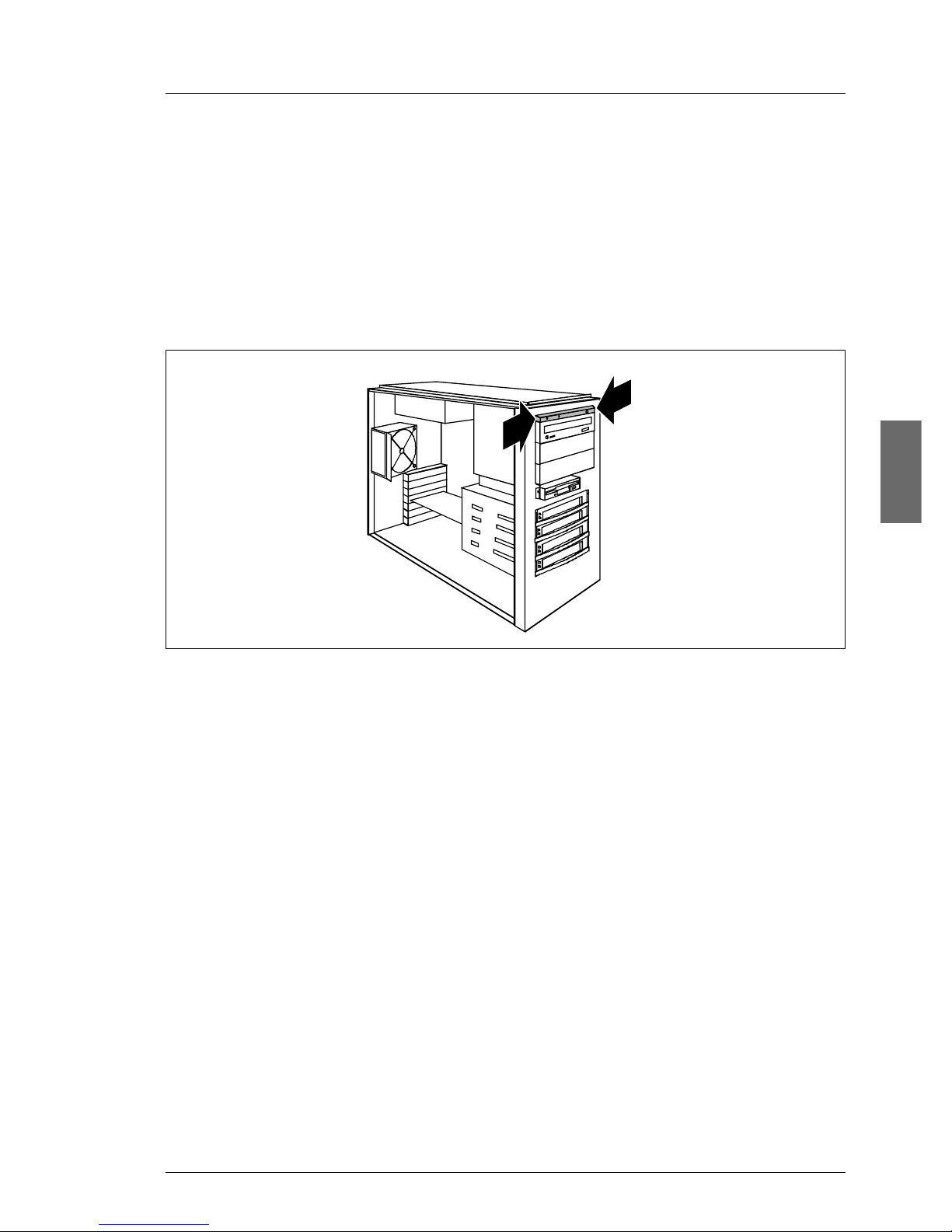
Figure 2: Removing the operating panel module
Ê Press the two metal tongues of the EasyClick rails inw ard (1) until the locking
mechanism is released.
Ê Pull the operating panel module forw ard out of its mounting location (2) until
you can remove the ribbon cable and the USB cable from the operating
panel board. Remove the two cables.
Ê Pull the operating panel module out of its bay as far as it is possible to get
access to the cable tie.
Ê Thread the two cables through the cable tie.
Ê Take the operating panel module out of its bay.
Ê Push the new operating panel module into its bay as far as it is possible to
have access to the cable tie.
Ê Thread the two cables through the cable tie.
Ê Push the operating panel module into its bay as far as it is possible to plug
the cables.
Service Supplement 15
Page 22
Replacing the floppy disk drive Replacement routines
Ê Connect the ribbon cable and the USB cable to the operating panel board
(see the board layout on page 37).
Ê Push the operating panel module into the housing until it engages.
Ê Close the server and connect all power plugs (for a detailed description see
the Options Guide).
4.3 Replacing the floppy disk drive
Ê Open the server and remove the front cover / rack front cover as described
in the section “Preparation” on page 13.
Ê Remove the power cable and the floppy cable at the rear side of the floppy
disk drive.
© cognitas. Gese l l sc hft für Technik-Dokumentati on mbH 2005 Pfad: L:\ T X150_S3\TX15 0S 3servsuppl \ T X 1 50S3_ss_e\T X150S3_ss_e.k04
2
1
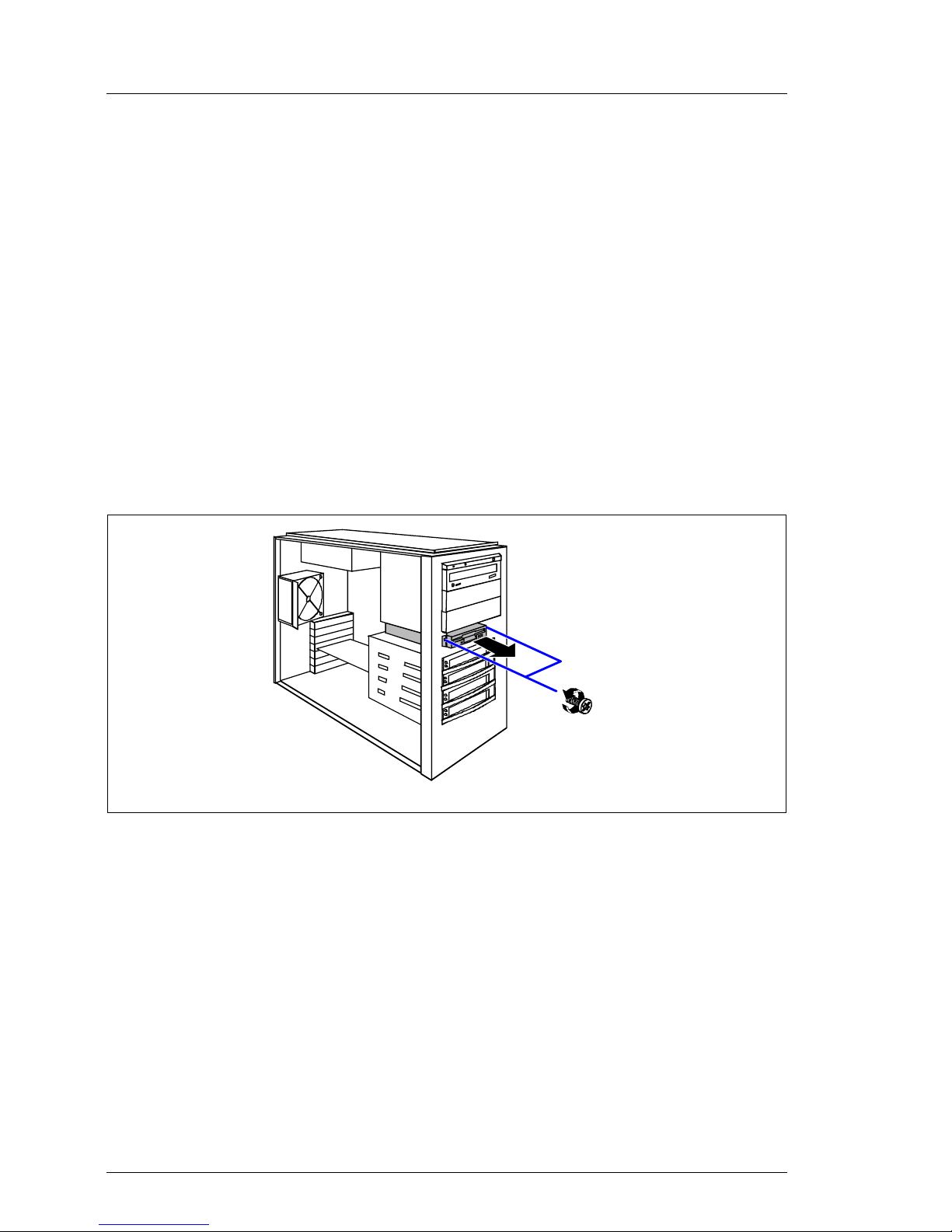
Figure 3: Removing the floppy disk drive with
Ê Remov e the two scre ws (1) that attach the drive holder to the housing front
side.
Ê Pull the drive holder out of the server (2).
16 Service Supplement
Page 23
Replacement routines Replacing the floppy disk drive
1
2
1
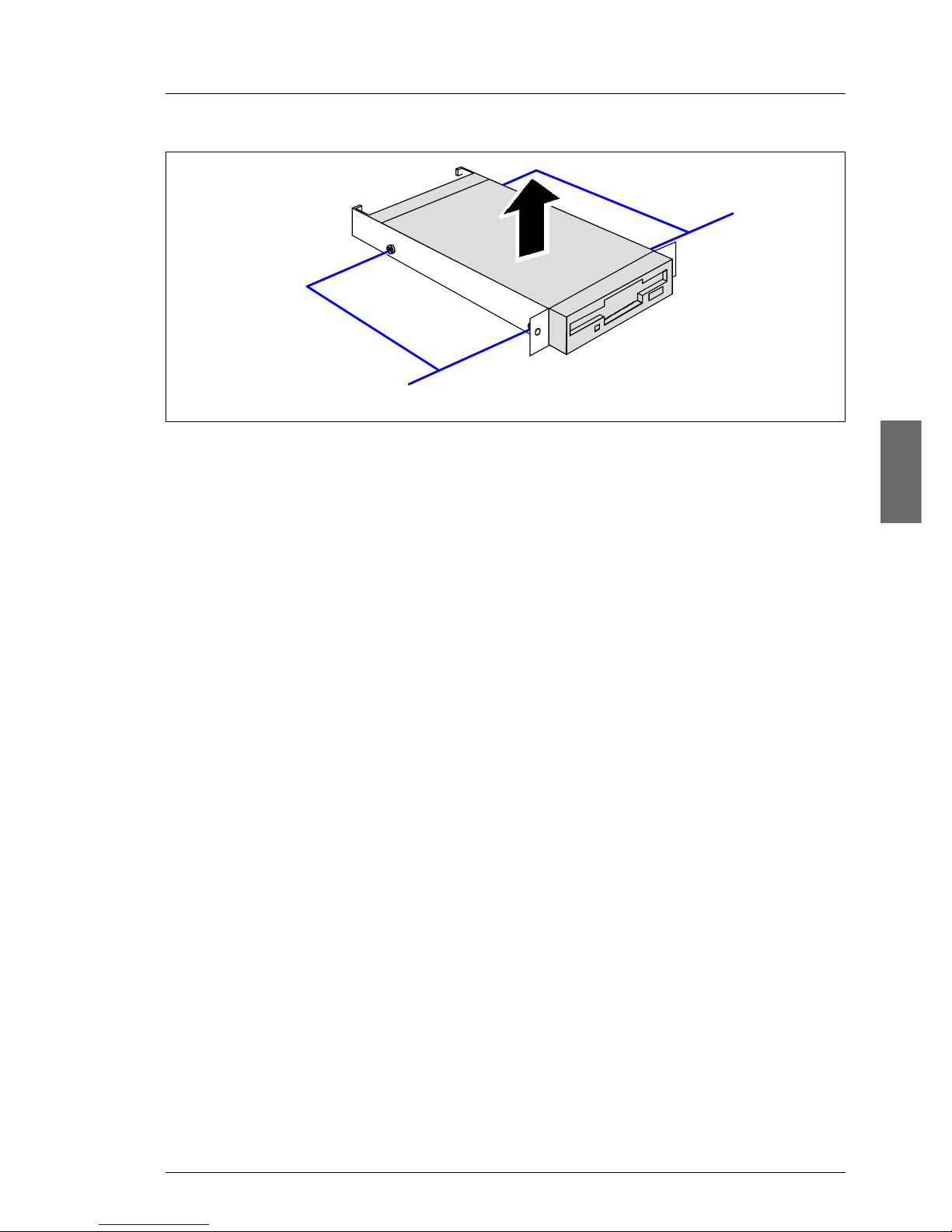
Figure 4: Removing the floppy disk drive from the holder
Ê Remov e two screws (1) on each side and tak e the floppy disk drive out of the
drive holder.
Ê Position the new floppy disk drive in the drive holder and fasten it with two
screws on each side.
Ê Push the drive holder with the floppy disk drive in its bay.
Ê Fasten the drive holder with two screws to the housing.
Ê Reconnect all cables.
Ê Close the server and connect all power plugs (for a detailed description see
the Options Guide).
Service Supplement 17
Page 24
Replacing the system fan Replacement routines
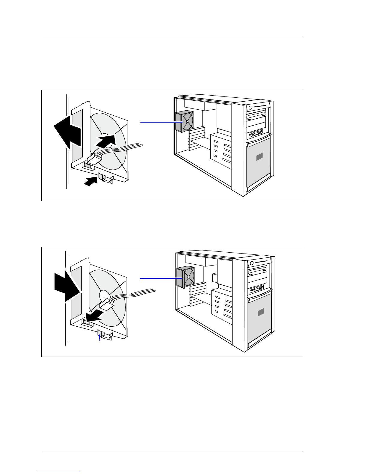
4.4 Replacing the system fan
Ê Open the server as described in the section “Preparation” on page 13.
3
1
2
© cognitas. Gese l l sc hft für Technik-Dokumentati on mbH 2005 Pfad: L:\ T X150_S3\TX15 0S 3servsuppl \ T X 1 50S3_ss_e\T X150S3_ss_e.k04
Figure 5: Removing the system fan
Ê Pull the cable off the system fan (1).
Ê Press on the clip (2) from behind and remove the system fan (3).
1
2
a
Figure 6: Installing the system fan
Ê Place the new system f an in the bay (1). The proper fan position can best be
judged from the outside at the rear side of the server. When doing so, make
sure the fan clip (a) engages properly.
Ê Connect the cable to the system fan (2).
Ê Close the server and connect all power plugs (for a detailed description see
the Options Guide).
18 Service Supplement
Page 25
Replacement routines Replacing the standard PS
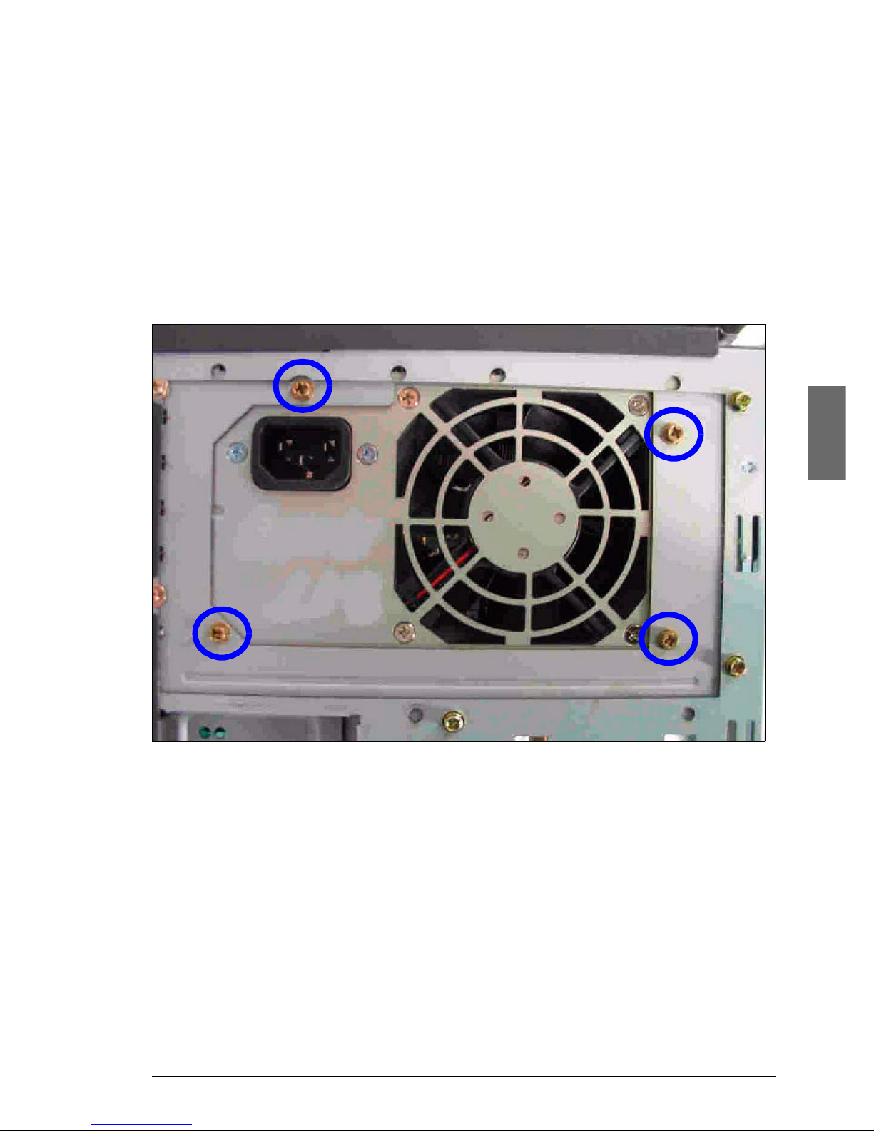
4.5 Replacing the standard PS
Ê Open the server as described in the section “Preparation” on page 13.
I You can replace the power supply without removing the adapter plate.
Ê Disconnect all power cab les fro m the system board and the drives (see the
cabling plans in the Appendix of the Options Guide).
Figure 7: Removing the screws
Ê Remove the four screws of the standard power supply (see the circles).
Service Supplement 19
Page 26
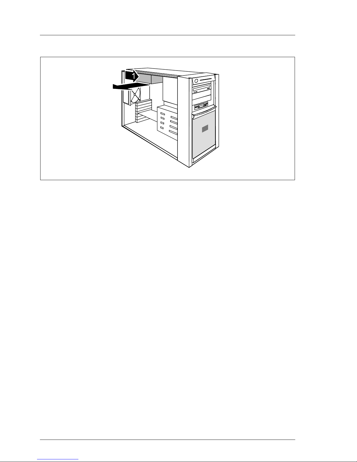
Replacing the Power backplane Replacement routines
2
Figure 8: Taking out the standard PS
© cognitas. Gese l l sc hft für Technik-Dokumentati on mbH 2005 Pfad: L:\ T X150_S3\TX15 0S 3servsuppl \ T X 1 50S3_ss_e\T X150S3_ss_e.k04
Ê Slide the standard power suppl y somewhat tow ard the inside (1) to detach it
from the adapter plate and take the standard power supply out toward the
side (2).
Ê Push the new power supply into the bay. Take care not to trap the cables.
Ê Fasten the power supply with four screws to the adapter plate.
Ê Connect all power cabl es to the system board and the drives (see the cabling
plans in the Appendix of the Options Guide).
Ê Close the server and connect all power plugs (for a detailed description see
the Options Guide).
4.6 Replacing the Power backplane
The Power backplane is mounted on the PS cage. The power cables are
permanently connected to the Power backplane.
Ê Open the server as described in the section “Preparation” on page 13.
Ê Push the green latch of the hot-plug power supply unit upward and pull the
power supply unit simultaneously out of the PS cage using the handle (see
also the Operating Manual).
20 Service Supplement
Page 27
Replacement routines Replacing the Power backplane
Ê If a second hot-plug power supply unit has been installed, remove this one
in the same way (if there is a dummy cover instead of a second hot-plug
power supply unit, this can remain in place).
I The Power backpl ane in the floorstand model is positioned directly under
the top cover and it makes sense to lay the server on a table with the
uncovered side facing upward. Place the server in such a way that the
feet can project over the edge.
Ê Remove all power cables from the system board and the drives (see the
cabling plans in the Appendix of the Options Guide).
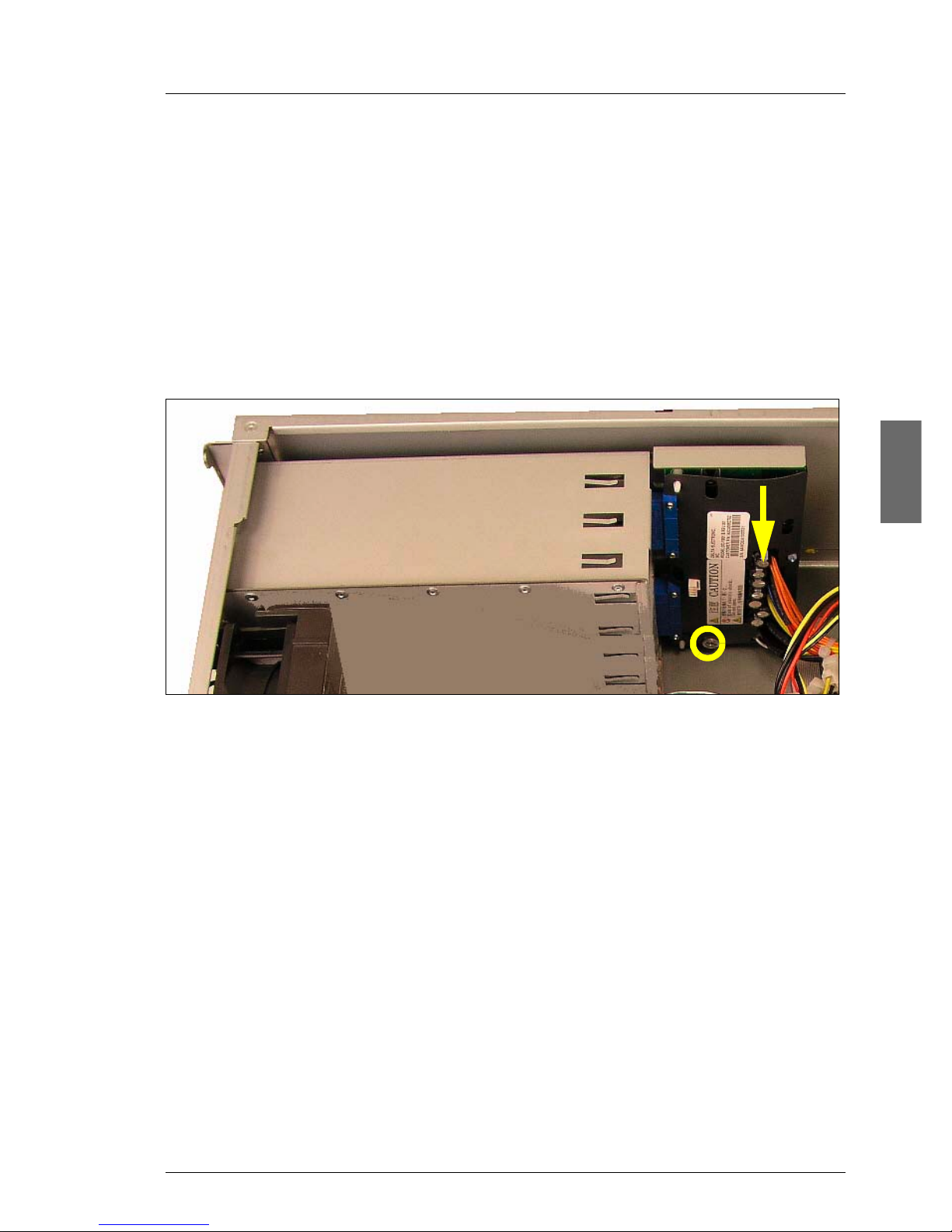
Figure 9: Removing the Power backplane
Ê Remove the knurled screw (see the circle).
Ê Push the P ower backplane downward (see direction of the arrow) until it gets
out of the three bolts of the PS cage. Take out the Power backplane.
Ê Insert the new P ower bac kplane and push the P ower bac kplane upward until
the three bolts of the PS cage engage.
Ê Fasten the Power backplane with the knurled screw in the PS cage.
Ê Plug the power cab les on the system board and the drives (see the cabling
plans in the Appendix of the Options Guide).
Ê Reinstall the hot-plug power supply unit(s).
Ê Close the server and connect all power plugs (for a detailed description see
the Options Guide).
Service Supplement 21
Page 28
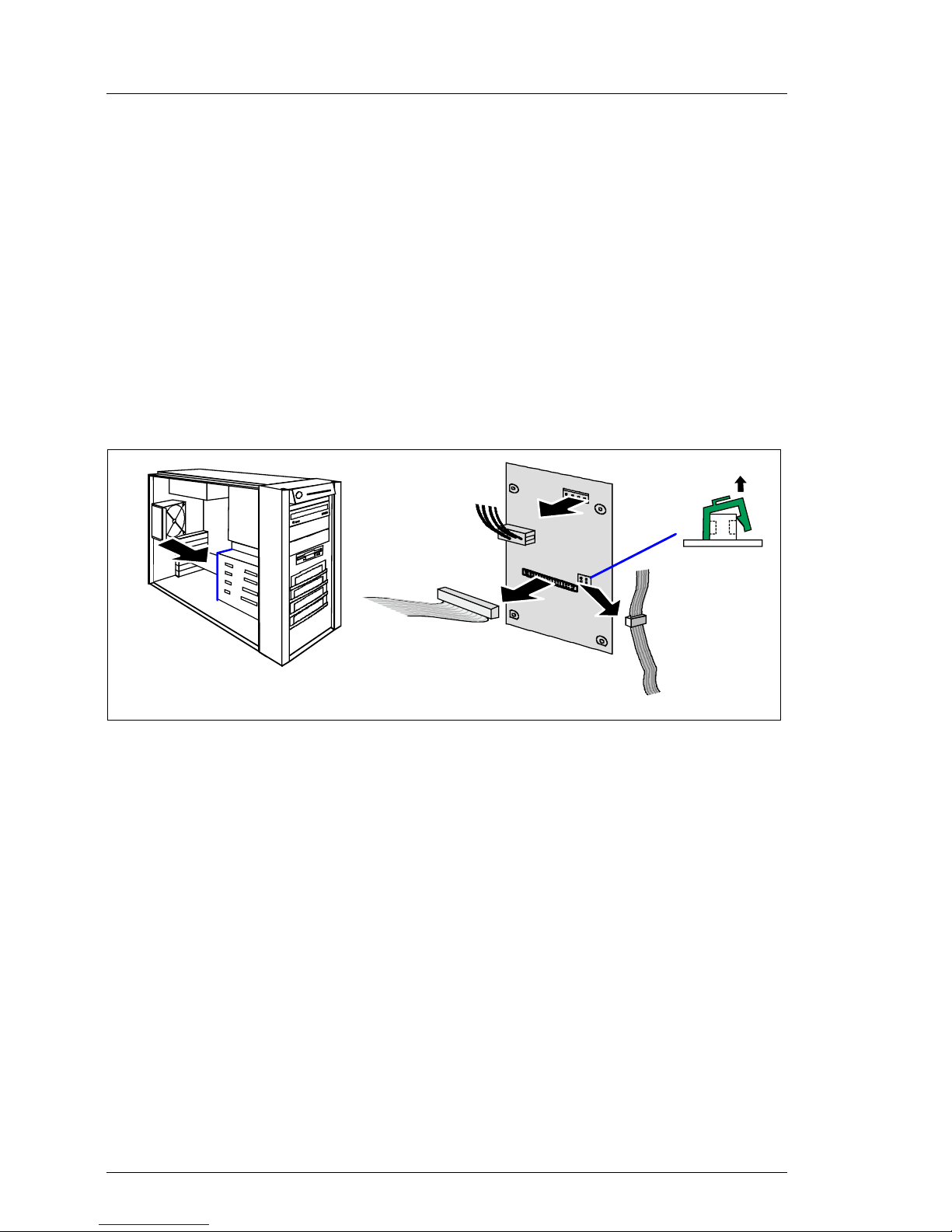
Replacing the SCSI backplane Replacement routines
4.7 Replacing the SCSI backplane
The SCSI backplane is mounted on the hard disk cage. It is not necessary to
remove the hard disk cage before replacing the SCSI backplane.
Ê Open the server as described in the section “Preparation” on page 13.
Ê Remov e all the hot-plug hard disk drives (f or a description see the Operating
Manual).
V CAUTION!
Check if all hard disk drives are uniquely identified so that you can
reinsert them into their original bays.
© cognitas. Gese l l sc hft für Technik-Dokumentati on mbH 2005 Pfad: L:\ T X150_S3\TX15 0S 3servsuppl \ T X 1 50S3_ss_e\T X150S3_ss_e.k04
2
1
1
Figure 10: Disconnecting cables
3
4
Ê Take the I2C cable out of the green cable clamp and remov e the cable clamp
(1).
Ê Pull out the connectors of the power cable (2), the SCSI cable (3) and the
2
I
C cable (4) from the SCSI backplane.
Ê Remove the four screws (two at each side) that fasten the SCSI backplane
holder to the hard disk cage.
Ê Take the SCSI backplane together with the holder out of the server. Be
careful with the isolation foil positioned on the rear side of the SCSI
backplane.
Ê Remove the isolation foil and lift the SCSI backplane from the holder.
Ê Insert the new SCSI backplane in the holder.
Ê Position the isolation foil.
22 Service Supplement
Page 29
Replacement routines Replacing the SATA backplane
Ê Fasten the SCSI backplane holder using the four screws on the hard disk
cage.
2
Ê Attach the connectors of the SCSI cable , the po wer cab le and the I
to the SCSI backplane (see the figure 10 on page 22).
2
Ê Attach the green cable clamp to the connect or of the I
cable in the cable clamp.
Ê Reinstall all hot-plug hard disk drives.
Ê Close the server and connect all power plugs (for a detailed description see
the Options Guide).
C cable and place the
C cable
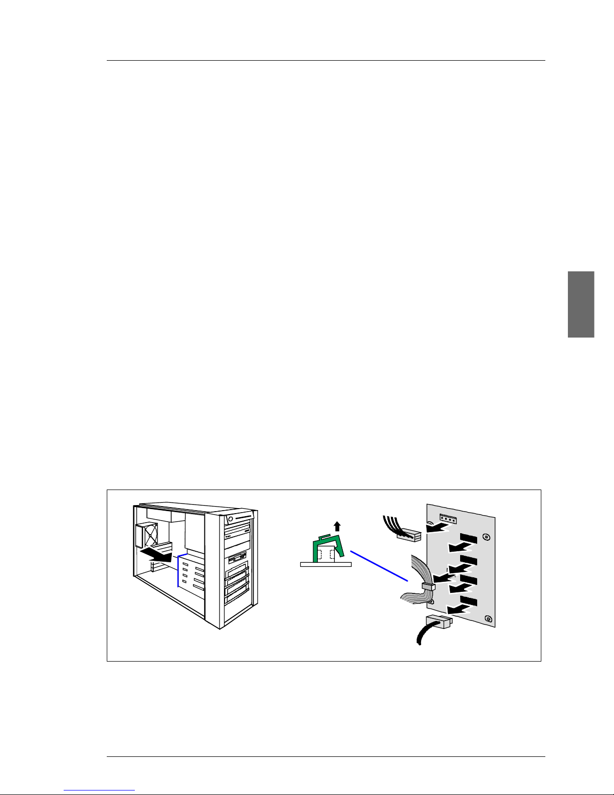
4.8 Replacing the SATA backplane
The SATA backplane is mounted on the hard disk cage. It is not necessary to
remove the hard disk cage before replacing the SATA backplane.
Ê Open the server as described in the section “Preparation” on page 13.
Ê Remov e all the hot-plug hard disk drives (for a desc ription see the Operating
Manual).
V CAUTION!
Check if all hard disk drives are uniquely identified so that you can
reinsert them into their original bays.
2
1
1
4 x
4
3
Figure 11: Disconnecting cables
Ê Take the I2C cable out of the green cable clamp and remov e the cable clamp
(1).
Service Supplement 23
Page 30

Replacing the IDTEMP combo Replacement routines
Ê Pull out the connectors of the power cab le (2), the f our SATA cables (3) and
2
the I
C cable (4) from the SATA backplane.
Ê Remove the four screws (two at each side) that fasten the SATA backplane
holder to the hard disk cage.
Ê Take the SATA backplane together with the holder out of the server. Be
careful with the isolation foil positioned on the rear side of the SATA
backplane.
Ê Remove the isolation foil and lift the SATA backplane from the holder.
Ê Insert the new SATA backplane in the holder.
Ê Position the isolation foil.
Ê Fasten the SATA backplane holder using the four screws on the hard disk
cage.
Ê Attach the connectors of the four SATA cables, the power cable and the I
© cognitas. Gese l l sc hft für Technik-Dokumentati on mbH 2005 Pfad: L:\ T X150_S3\TX15 0S 3servsuppl \ T X 1 50S3_ss_e\T X150S3_ss_e.k04
cable to the SATA backplane (see the figure 11 on page 23).
Ê Attach the green cable clamp to the connector of the I
2
C cable and place the
2
C
cable in the cable clamp.
Ê Reinstall all hot-plug hard disk drives.
Ê Close the server and connect all power plugs (for a detailed description see
the Options Guide).
4.9 Replacing the IDTEMP combo
This board includes two important system components:
– EEPROM for the chassis ID and ident number of the server
– temperature sensor for monitoring the environment temperature
The current temperature values and EEPROM data are transmitted to the
system board via the connected I2C bus.
The IDTEMP combo must be correctly installed in order:
– to monitor the temperature correctly,
– to enable the server management to display the correct system picture,
– to install the server using ServerStart.
24 Service Supplement
Page 31

Replacement routines Replacing the IDTEMP combo
V CAUTION!
The IDTEMP combo may not be changed because of the information
which is in the EEPROM to identify the system.
If the combo is defective, a spare part must be ordered specially by
specifying the ident number (see the type label).
The IDTEMP combo is situated on a separate holder under the hard disk cage .
Ê Open the server as described in the section “Preparation” on page 13.
Figure 12: Removing the holder
Ê Push the holder in direction of the arrow.
Ê Take out the holder carefully.
Ê Remove the green cable clamp from the connector of the I
Ê Remove the I
2
C cable from the connector on the IDTEMP combo.
Ê Remove the IDTEMP combo from the holder.
Ê Plug the new IDTEMP combo in the holder.
Ê Plug the I
Service Supplement 25
2
C cable on the connector on the IDTEMP combo.
2
C cable.
Page 32

Replacing the intrusion switches Replacement routines
Ê Plug the green cable clamp on the connector of the I2C cable.
Ê Insert the holder in a slight angle. Make sure that the cables are routed as
shown in figure 12 on page 25.
Ê Push the holder in direction of the front side until the holder engage in the
bottom of the chassis.
Ê Close the server and connect all power plugs (for a detailed description see
the Options Guide).
4.10 Replacing the intrusion switches
In the floorstand model two intrusion detection switches monitor the removing
of the left side cover and the hard disk cover. In the rack model only one
intrusion switch is active, this one monitors the removing of the top cover.
© cognitas. Gese l l sc hft für Technik-Dokumentati on mbH 2005 Pfad: L:\ T X150_S3\TX15 0S 3servsuppl \ T X 1 50S3_ss_e\T X150S3_ss_e.k04
One switch is situated at the left (floorstand model) or the top (rack model) side
of the hard disk cage, the other switch at the front cover beneath the hard disk
cage. The two i ntrusion detection s witc hes are serially connected on one ca ble
and have to be replaced in pairs.
Ê Open the server and remove the front cover / rack front cover as described
in the section “Preparation” on page 13.
Ê Remove the IDTEMP combo with its holder as shown in figure 12 on
page 25.
26 Service Supplement
Page 33

Replacement routines Replacing the intrusion switches
Figure 13: Removing screws and intrusion switch 1
Ê Remove the two screws (see the arrows) and take out the intrusion switch.
1
2
1
1
Figure 14: Removing the screws and intrusion switch 2
Ê Remove the two screws (1) and take out the intrusion switches inward (2).
Ê Pull the first removed intrusion switch out of the cable clamp.
Service Supplement 27
Page 34

Replacing the processor Replacement routines
Ê Remov e the intrusion switch cable from the connector on the system board
(see also the Technical Manual of the system board).
V CAUTION!
Note the cable routing.
Ê Plug the new intrusion switch cable to the connector on the system board.
Ê Route the intrusion switch cable.
Ê Position the intrusion switch with the three wires on the front cover and
fasten it with two screws.
Ê Insert the intrusion switch with the two wires in its holder and fasten the
switch with two screws.
Ê Reinsert the IDTEMP combo with its holder as shown in figure 12 on
page 25.
© cognitas. Gese l l sc hft für Technik-Dokumentati on mbH 2005 Pfad: L:\ T X150_S3\TX15 0S 3servsuppl \ T X 1 50S3_ss_e\T X150S3_ss_e.k04
Ê Close the server and connect all power plugs (for a detailed description see
the Options Guide).
4.11 Replacing the processor
V CAUTION!
Processors are modules which can react extremely s ensitively to electrostatic discharges and which must therefore alw ays be handl ed with care.
After a processor has been remov ed from its protectiv e sleev e or from its
socket, place it with its smooth side down on a non-conducting, antistatic
surface. Never push a processor over a surface.
Ê Open the server as described in the section “Preparation” on page 13.
28 Service Supplement
Page 35

Replacement routines Replacing the processor
1
4
Figure 15: Removing the heat sink
3
2
Ê Loosen the four screws in a crossover pattern.
Ê Loosen the heat sink by turning it back and forth and then lift it out.
Ê Remove the residual thermal paste from the underside of the heat sink.
Ê Clean the underside of the heat sink using a lint-free cloth.
Service Supplement 29
Page 36

Replacing the processor Replacement routines
2
1
Figure 16: Removing an old processor
Ê Press down the lever (1) and unhook it.
Ê Fold up the frame.
© cognitas. Gese l l sc hft für Technik-Dokumentati on mbH 2005 Pfad: L:\ T X150_S3\TX15 0S 3servsuppl \ T X 1 50S3_ss_e\T X150S3_ss_e.k04
Ê Lift the installed processor carefully out of the socket (2).
1
Figure 17: Inserting a new processor
a
Ê Remove the protective cap from the bottom side of the new processor.
Ê Position the new processor over the socket and then carefully press it into
the socket (1).
V CAUTION!
The processor can only be installed in one particular direction. Note
the marking on one of the corners. To av oid damaging the pins or the
processor, do not fo rce it into the socket.
30 Service Supplement
Page 37

Replacement routines Replacing the processor
1
Figure 18: Fixing the processor
Ê Fold down the frame (1).
2
3
V CAUTION!
The processor holder must fall do wn by itself . Do not close with f orce,
because soldering pads may be damaged.
Ê Press the lever slowly downward (2) until it is hooked in again (3).
Ê Apply a small amount of thermal paste to the upper side of the new
processor.
Ê Ensure a thin and even distribution of the thermal paste.
Service Supplement 31
Page 38

Replacing the processor Replacement routines
© cognitas. Gese l l sc hft für Technik-Dokumentati on mbH 2005 Pfad: L:\ T X150_S3\TX15 0S 3servsuppl \ T X 1 50S3_ss_e\T X150S3_ss_e.k04
Figure 19: Position of the holes to fasten the heat sink
Ê Position the heat sink carefully on the processor.
V CAUTION!
The heat sink must be positioned in the way that a wide side of the
heat sink is in direction of the system fan to enable the air flow through
the ribs.
Ê Position the screws in the holes carefully, making sure they are upright.
32 Service Supplement
Page 39

Replacement routines Replacing the processor
1
4
Figure 20: Mounting the heat sink
3
2
Ê Tighten the four screws crosswise. Follow the following steps:
1. T urn screw no .1 two/three turns, then will be no tension on the processor
when tightening the next screws.
2. Tighten screws no. 2, 3 and 4 in this order.
3. Tighten screw no.1 finally.
Tighten all screws as far as they will go with a torque of 0.6 NM.
Ê Close the server and connect all power plugs (for a detailed description see
the Options Guide).
Service Supplement 33
Page 40

Replacing the system board Replacement routines
4.12 Replacing the system board
Ê Open the server as described in the section “Preparation” on page 13.
Ê Lay the server on a table with the uncovered side facing upward. Place the
server in such a way that the feet can project over the edge.
Ê Remove all external cables.
Ê Remove all controllers from their slots (for a description see the Operating
Manual and the Options Guide). Tak e note of the slots of the controllers and
the cabling.
Ê Remove the system fan (see the section “Replacing the system fan” on
page 18).
Ê Remove the processor (see the section “Replacing the processor” on
page 28).
© cognitas. Gese l l sc hft für Technik-Dokumentati on mbH 2005 Pfad: L:\ T X150_S3\TX15 0S 3servsuppl \ T X 1 50S3_ss_e\T X150S3_ss_e.k04
Ê Remove the memory modules (for a description see the Options Guide).
Ê Remove all cables which may be connected to the system board.
34 Service Supplement
Page 41

Replacement routines Replacing the system board
1
4
8
2
5
9
3
6
7
1110
Figure 21: Removing the screws
Ê Remove the eleven screws from the system board.
Ê Lift the system board slightly using the socket of PCI slot 5, thereby you lift
the system board out of the centre rings of the spacer bolts.
Ê Carefully lift the system board (using both hands) out of the chassis in a
slight angle. Thereby you pull the connectors out of the connector panel.
V CAUTION!
Always take the system board with both hands!
Never lift the system board one-sided or at the heat sink, because
the solder connections between the socket and the system board
come under tension and increase the risk of damage and
malfunction!
Don’t damage the EMI springs to comply with applicable EMC regulations and satisfy cooling requirements and fire protection measures.
Ê Place the removed and the new system board on an antistatic surface.
Service Supplement 35
Page 42

Ê Remove the protective plastic cover from the processor socket of the new
system board and fit it onto the socket of the defective system board which
will be sent back to spares.
I Returned system boards without this cover probably have to be
scrapped.
Ê Check the settings on the new system board (for a description see the
Technical Manual of the system board).
Ê Insert the system board by holding it at a slight angle. Slide the connectors
into the connector panel.
Ê Lower the system board carefully into the chassis.
Ê Adjust the system board. If necessary adjust the position of the system
board with a gentle twisting motion.
I When the system board is in the right position, the centre rings engage
© cognitas. Gese l l sc hft für Technik-Dokumentati on mbH 2005 Pfad: L:\ T X150_S3\TX15 0S 3servsuppl \ T X 1 50S3_ss_e\T X150S3_ss_e.k04
Ê Fasten the system board with the eleven screws.
with the holes indicated. The centre rings are placed under the screw
positions 1 and 5.
Ê Reconnect the cables to their original connectors (see also the c abling plans
in the Options Guide).
Ê Install the memory modules (for a description see the Options Guide).
Ê Install the processor (see the section “Replacing the processor” on
page 28).
Ê Install the system fan (see the section “Replacing the system fan” on
page 18).
Ê Install all controllers in their former slots (f or a description see the Operating
Manual and Options Guide).
Ê Close the server and connect all power plugs (for a detailed description see
the Options Guide).
Ê Connect all external cables.
V CAUTION!
After installing the new system board, it is necessary to update the BIOS
to ensure proper operation (for a description see the BIOS Manual).
Page 43

5 Appendix
5.1 Board layout
I The board layout of the system board is described in the Technical
Manual of the system board D1979.
5.1.1 Operating panel board
Part number: A3C40050401
1 Connector operating panel cable
2 Connector USB cable
I The operating panel board is included in the spare part „operating panel
module“ (C26361-K644-Z331).
Service Supplement 37
21
Page 44

Board layout Appendix
5.1.2 SCSI backplane
Part number: A3C40020516
You will find the SCSI backplane with 4 slots for hard disk modules on the hard
disk cage. The termination is done by the SCSI backplane
2
SCSI ID3
© cognitas. Gesel l sc hft für Technik-Dokumenta tion mbH 2005 Pfad: L:\T X150_S3\TX150S3servsu ppl\TX150S3_ss_e\TX150S3_ss_e.anh
4
SCSI ID 2
5
1
1 X 5 SC SI input connector 4 LEDs
2 X6 Power connector 5 SCA connect ors (ID0 to ID3)
3 X 7 SM B connector (i²C bus)
3
SCSI ID 1
SCSI ID 0
The LEDs are made visible at the front side of the mounting frames via light
conductors, which are situated at the mounting fr ames of the drives. You will find
the description of the LEDs in the Operating Manual TX150 S3.
38 Service Supplement
Page 45

Appendix Board layout
5.1.3 SATA backplane
Part number: A3C40040589
You will find the SATA backplane with 4 slots for SAT A hard disk modules located
on the hard disk cage.
4
3
5
6
8
2
1
7
1I2C bus connector (X11) 5 not used (Program con nec t or)
2 SMB connector (I
3 Jumper FW Run (X13)
jumper is not set
4 Connector power supply ( X 9) 8 SATA connectors for hard disk drives
The LEDs are made visible on the front side of the mounting frames via light
conductors, which are situated at the mounting frames of the drives. Th e signal
of the LEDs is the same as for SCSI hard disk drives. The controlling of the
LEDs does only work if a driver has been loaded.
Service Supplement 39
2
C bus, X10) 6 LEDs
7 Connectors to SATA controller (HDD0
- HDD3)
Page 46

Board layout Appendix
5.1.4 Power backplane
Part number: A3C40052762
© cognitas. Gesel l sc hft für Technik-Dokumenta tion mbH 2005 Pfad: L:\T X150_S3\TX150S3servsu ppl\TX150S3_ss_e\TX150S3_ss_e.anh
2
1
1 Connector power supply m odule 1
2 Connector power supply m odule 2
40 Service Supplement
Page 47

Index
E
ESD (devices sensitiv e to electrostatic
discharge) 11
F
floppy disk drive 16
I
IDTEMP combo 24
intrusion detection switches 26
L
light-emitting diode (LED) 11
lithium battery 9
M
meaning of the symbols 4
N
notational conventions 4
note about the laser 11
O
operating panel board 37
operating panel module 15
P
Power backplane 20, 40
processor 28
S
SATA backplane 23, 39
SCSI backplane 22, 38
standard PS 19
system board 33
T
target group 1
Service Supplement 41
Page 48

© cognitas. Gese l l sc hft für Technik-Dokumenta tion mbH 2005 Pfad: L:\ T X 150_S3\TX150S 3servsuppl\TX150S3_s s_e\TX150S3_ss_e.six
Page 49

Fujitsu Siemens Computers GmbH
User Documentation
81730 München
Germany
Fax: (++49) 700 / 372 00000
email: manuals@fujitsu-siemens.com
http://manuals.fujitsu-siemens.com
Submitted by
Comments on PRIMERGY TX150 S3
Server System
Comments
Suggestions
Corrections
✁
Page 50

© cognitas. Gese l l sc hf t für Technik-Dokumentation mbH 2005 Pfad: L:\ T X1 50_S3\TX150S 3servsuppl\TX150S3_ss_e\TX150S3_s s_e.nac
Page 51

Fujitsu Siemens Computers GmbH
User Documentation
81730 München
Germany
Fax: (++49) 700 / 372 00000
email: manuals@fujitsu-siemens.com
http://manuals.fujitsu-siemens.com
Submitted by
Comments on PRIMERGY TX150 S3
Server System
Comments
Suggestions
Corrections
✁
Page 52

© cognitas. Gese l l sc hf t für Technik-Dokumentation mbH 2005 Pfad: L:\ T X1 50_S3\TX150S 3servsuppl\TX150S3_ss_e\TX150S3_s s_e.nac
Page 53

PRIMERGY
PRIMERGY TX150 S3
Server System
Options Guide
Susanne Däschlein
Fujitsu Siemens Computers GmbH München
81730 München
e-mail: email: manuals@fujitsu-siemens.com
Tel.: (089) 61001155
Fax: (++49) 700 / 372 00000
U41604-Z156-1-76
Sprachen: En
Edition January 2005
Page 54

This manual is printed on
paper treated with
chlorine-free bleach.
Comments… Suggestions… Corrections…
The User Documentation Department would like to
know your opinion of this manual. Your feedback helps
us optimize our documentation to suit your individual
needs.
Fax forms for sending us your comments are included in
the back of the manual.
There you will also find the addresses of the relevant
User Documentation Department.
Certified documentation
according to DIN EN ISO 9001:2000
To ensure a consistently high quality standard and
user-friendliness, this documentation was created to
meet the regulations of a quality management system
which complies with the requirements of the standard
DIN EN ISO 9001:2000.
cognitas. Gesellschaft für Technik-Dokumentation mbH
www.cognitas.de
Copyright and Trademarks
Copyright © 2005 Fujitsu Siemens Computers GmbH.
All rights reserved.
Delivery subject to availability; right of technical modifications reserved.
All hardware and software names used are trademarks of their respective manufacturers.
Page 55

Introduction
Procedure
Safety notes
Preparation
Main memory
Accessible drives
Controller in the PCI slots
RemoteView components
External SCSI interface
Conversion standard PS to hot-plug PS
Continued
Page 56

Page 57

Converting from the floorstand model to the rack model
Completion
Appendix
Abbreviations, Related publications and Index
Page 58

Page 59

U41604-Z156-1-76 Options Guide
Contents
1Introduction. . . . . . . . . . . . . . . . . . . . . . . . . . . . 1
1.1 Overview of the documentation . . . . . . . . . . . . . . . . . . 1
1.2 Extensions and conversions . . . . . . . . . . . . . . . . . . . . 2
1.3 Notational conventions . . . . . . . . . . . . . . . . . . . . . . . 4
2 Procedure . . . . . . . . . . . . . . . . . . . . . . . . . . . . . 5
3 Safety notes . . . . . . . . . . . . . . . . . . . . . . . . . . . 7
4 Preparation . . . . . . . . . . . . . . . . . . . . . . . . . . . 13
4.1 Floorstand model . . . . . . . . . . . . . . . . . . . . . . . . 13
4.1.1 Opening the server . . . . . . . . . . . . . . . . . . . . . . . 13
4.1.2 Removing the front cover . . . . . . . . . . . . . . . . . . . . 14
4.1.3 Removing the hard disk cover . . . . . . . . . . . . . . . . . . 15
4.2 Rack model . . . . . . . . . . . . . . . . . . . . . . . . . . . 16
4.2.1 Opening the server . . . . . . . . . . . . . . . . . . . . . . . 16
4.2.2 Removing the rack front cover . . . . . . . . . . . . . . . . . . 19
5Main memory . . . . . . . . . . . . . . . . . . . . . . . . . . 21
5.1 Equipping rules . . . . . . . . . . . . . . . . . . . . . . . . . 21
5.2 Extending/replacing the main memory . . . . . . . . . . . . . 22
6 Accessible drives . . . . . . . . . . . . . . . . . . . . . . . 25
6.1 Installing an accessible 5.25-inch drive . . . . . . . . . . . . . 25
6.2 Installing the hard disks extension box . . . . . . . . . . . . . 29
7 Controller in the PCI slots . . . . . . . . . . . . . . . . . . . 31
7.1 Installing a controller . . . . . . . . . . . . . . . . . . . . . . . 32
7.2 PCI slot assembling . . . . . . . . . . . . . . . . . . . . . . . 34
8 RemoteView components . . . . . . . . . . . . . . . . . . . 35
8.1 RemoteView Service Board S2 LP . . . . . . . . . . . . . . . 35
9 External SCSI interface . . . . . . . . . . . . . . . . . . . . 39
9.1 Installing the external SCSI interface . . . . . . . . . . . . . . 39
10 Conversion standard PS to hot-plug PS . . . . . . . . . . . 41
11 Converting from the floorstand model to the rack model . . 53
12 Completion . . . . . . . . . . . . . . . . . . . . . . . . . . . 59
12.1 Floorstand model . . . . . . . . . . . . . . . . . . . . . . . . 59
Page 60

Options Guide U41604-Z156-1-76
Contents
12.1.1 Attaching the hard disk cover . . . . . . . . . . . . . . . . . . . 59
12.1.2 Attaching the front cover . . . . . . . . . . . . . . . . . . . . . 60
12.1.3 Closing the server . . . . . . . . . . . . . . . . . . . . . . . . . 61
12.2 Rack model . . . . . . . . . . . . . . . . . . . . . . . . . . . . 62
12.2.1 Attaching the rack front cover . . . . . . . . . . . . . . . . . . 62
12.2.2 Closing the server . . . . . . . . . . . . . . . . . . . . . . . . . 64
13 Appendix . . . . . . . . . . . . . . . . . . . . . . . . . . . . . 67
13.1 Cabling . . . . . . . . . . . . . . . . . . . . . . . . . . . . . . 67
13.1.1 SCSI version . . . . . . . . . . . . . . . . . . . . . . . . . . . 67
13.1.2 SATA version . . . . . . . . . . . . . . . . . . . . . . . . . . . 71
Abbreviations . . . . . . . . . . . . . . . . . . . . . . . . . . . . . . . . 73
Related publications . . . . . . . . . . . . . . . . . . . . . . . . . . . . 79
Index . . . . . . . . . . . . . . . . . . . . . . . . . . . . . . . . . . . . 81
Page 61

U41604-Z156-1-76 Options Guide 1
1 Introduction
The PRIMERGY TX150 S3 Server is an Intel-based server for medium-sized
networks and large companies. The server is suitable for use as a file server as
well as an application, information, or Internet server. It is available as a floorstand or rack model. The floorstand model can be converted to a rack model
using an optional conversion kit.
1.1 Overview of the documentation
I PRIMERGY manuals are available in PDF format on the ServerBooks CD
which is supplied in the ServerView Suite package for every server
system.
These PDF files can also be downloaded free of charge from the
Internet: at http://manuals.fujitsu-siemens.com you will find an overview
page with the online documentation available on the Internet. You can go
to the PRIMERGY Server documentation by clicking on “intel based
Servers”.
Concept and target groups
This Options Guide shows you how you can expand and upgrade the server.
I The Operating Manual for the server describes how you install/remove
the hot-plug components.
The activities described in this manual may only be performed by technicians,
service personnel or technical specialists.
Additional documentation about the server
The PRIMERGY TX150 S3 documentation comprises the following additional
manuals:
– The “Security” manual (printed copy always supplied with the server, and
available as a PDF file on the ServerBooks CD supplied)
– The “Guarantee” manual (printed copy always supplied with the server, and
available as a PDF file on the ServerBooks CD supplied)
– The Operating Manual for the PRIMERGY TX150 S3 (PDF available on the
ServerBooks CD supplied)
Page 62

2 Options Guide U41604-Z156-1-76
Extensions and conversions Introduction
– The Technical Manual for the system board D1979 (PDF available on the
ServerBooks CD supplied)
– The “BIOS Setup” manual (PDF available on the ServerBooks CD supplied)
– The “PRIMERGY ServerView Suite - ServerStart” manual (printed copy
always supplied with the server, and available as PDF file on the ServerBooks
CD supplied)
– The “Global Array Manager Client Software User’s Guide” (PDF available on
the ServerBooks CD supplied)
– The “Integrated Mirroring User’s Guide” (PDF available on the ServerBooks
CD supplied)
I You can order a supplementary ServerBooks CD by sending an e-mail to
the following address, quoting your server data:
Reklamat-PC-LOG@fujitsu-siemens.com
Further sources of information:
– Technical Manual on the relevant rack
– Manual on the monitor
– Manual on ServerView Server Management
– Manual on the RemoteView Remote Test and Diagnostics System
– Documentation on boards and drives
– Documentation on your operating system
– Information files on your operating system
(see also “Related publications” on page 79)
1.2 Extensions and conversions
Extension of the main memory
The four slots for the main memory are suitable for DDR1 333/400 MHz (unbuffered) SDRAM memory modules. The organization in two memory banks, 1 and
2, permits rapid memory access with two-way interleaving.
If the memory modules are populated in pairs, each pair must consist of
identical memory modules (2-way interleaved mode).
Additional SATA hard disk drives
In the SATA version four bays are available for SATA hard disk drives.
Page 63

U41604-Z156-1-76 Options Guide 3
Introduction Extensions and conversions
Additional accessible drives
Three 5.25-inch bays are available for accessible drives. The top side bay is
already occupied by a CD/DVD ROM drive.
Hard disks extension box
In the SCSI version the two lower 5.25-inch bays for accessible drives can be
used to integrate a hard disks extension box.
The hard disks extension box enables up to three additional HDD modules to be
integrated. Each HDD module can accommodate a SCSI hard disk drive with
an SCA (Single Connector Attachment) interface and a height of at most 1 inch.
The connection to the SCSI backplane is made without cables via the SCA
interface. This makes it simple to plug in or pull out the HDD modules. If the
server has a RAID controller and the corresponding RAID configuration,
defective HDD modules can also be replaced while the system is operating.
Additional controllers in the PCI slots
The system board offers six PCI slots: 2 x PCI-X (64 Bit / 66 MHz), 3 x PCI (32
Bit / 33 MHz) and 1 x PCI-Express x1 slot.
The PCI slot 2 is prepared for Zero Channel RAID (ZCR).
RemoteView Service Board S2 LP
The RemoteView Service Board S2 LP (RSB S2 LP) is a PCI board with a
completely independent system, i.e. it has its own operating system with Web
server and SNMP agents and can optionally be equipped with an external
power supply. The RSB S2 LP permits remote diagnosis for system analysis,
remote system configuration and remote restart even in the event of operating
system failure or hardware faults. It has its own LAN connection and its own
COM port. All the functions of the RSB S2 LP are thus available either via a LAN
or modem.
External SCSI interface
If the internal hard disks are connected via a PCI RAID controller, one channel
of the on-board controller can also be made available for connecting a
peripheral cabinet SX10 via an external SCSI interface.
Page 64

4 Options Guide U41604-Z156-1-76
Notational conventions Introduction
Conversion standard power supply to hot-plug power supply
The standard power supply can be replaced by a hot-plug power supply. The
hot-plug power supply consists of two power supply modules.
If one power supply module fails, the other power supply module guarantees the
unrestricted operation and the defective power supply module can be replaced
be replaced while the system is operating (hot-plug).
Conversion of the floorstand model to a rack model
The floorstand model can optionally be converted so that the server can be
integrated into the common rack systems.
1.3 Notational conventions
The following notational conventions are used in this manual:
Text in italics indicates commands, menu items or software programs.
„Quotation marks“ indicate names of chapters and terms that are being
emphasized.
Ê describes activities that must be performed in the order
shown.
V CAUTION! pay particular attention to texts marked with this symbol.
Failure to observe this warning may endanger your life,
destroy the system or lead to the loss of data.
I indicates additional information, notes and tips.
Table 1: Notational conventions
Page 65

U41604-Z156-1-76 Options Guide 5
2Procedure
V CAUTION!
The actions described in these instructions should only be performed by
technicians, service personnel or technical specialists. Equipment
repairs should only be performed by authorized, qualified staff. Any
unauthorized opening and improper repairs could expose the user to
risks (electric shock, energy hazards, fire hazards) and could also
damage the equipment. Please note that any unauthorized opening of
the device will result in the invalidation of the warranty and exclusion from
all liability.
Ê First of all please familiarize yourself with the safety instructions in the
section chapter “Safety notes” on page 7 et seqq. .
Ê Ensure that all required manuals (see “Additional documentation about the
server” on page 1) are available, printing out the PDF files if necessary. You
will definitely need the Operating Manual for the server and the Technical
Manual for the system board.
Ê Shut down the server correctly, switch it off, pull out the power plug(s), and
open the server as described in the chapter “Preparation” on page 13 et
seqq. .
Ê Extend or upgrade your server as described in the relevant chapter.
I The Operating Manual for the server describes how you
install/remove the hot-plug components.
I Procedures which are identical for the floorstand and rack models are
only described for the floorstand model.
Ê Close the server, connect it to the power outlet, and switch it on as described
in the chapter “Completion” on page 59 et seqq. .
Ê Start the operating system and, if necessary, configure it as required (see
the Operating Manual).
Page 66

Page 67

U41604-Z156-1-76 Options Guide 7
3 Safety notes
I The following safety notes are also provided in the “Safety” manual.
This device complies with the relevant safety regulations for data processing
equipment.
If you have any questions about where you can set up the device, contact your
sales outlet or our customer service team.
V CAUTION!
The actions described in these instructions should only be performed by
technicians, service personnel or technical specialists. Equipment
repairs should only be performed by authorized, qualified staff. Any
unauthorized openings and improper repairs could expose the user to
risks (electric shock, energy hazards, fire hazards) and could also
damage the equipment. Please note that any unauthorized openings of
the device will result in the invalidation of the warranty and exclusion from
all liability.
Before operating the device
V CAUTION!
● During installation and before operating the device, observe the
instructions on environmental conditions for your device.
● If the device is brought in from a cold environment, condensation may
form both inside and on the outside of the machine.
Wait until the device has acclimatized to room temperature and is
absolutely dry before starting it up. Material damage may be caused
to the device if this requirement is not observed.
● Transport the device only in the original packaging or in packaging
that protects it from knocks and jolts.
Page 68

8 Options Guide U41604-Z156-1-76
Safety notes
Installation and operation
V CAUTION!
● If the rack model is integrated in an installation that receives power
from an industrial (public) power supply network with the IEC309
connector, the (public) power supply protection must comply with the
requirements for the non-industrial (public) power supply networks for
the type A connector.
● The server automatically sets itself to a voltage in the range of
100 V to 240 V. Make sure that your local voltage is within this range.
● This device has a specially approved power cable and must only be
connected to a grounded insulated socket.
● Ensure that the power socket on the device or the grounded wall
outlet is freely accessible.
● The ON/OFF button does not disconnect the device from the mains
voltage. To disconnect the line voltage completely, remove the power
plug(s) from the grounded insulated socket(s).
V CAUTION!
● Always connect the device and the attached peripherals to the same
power circuit. Otherwise you run the risk of losing data if, for example,
the central processing unit is still running but the peripheral device
(e.g. storage subsystem) has failed during a power outage.
● Data cables to peripheral devices must be adequately shielded.
● To the LAN wiring the requirements apply in accordance with the
standards EN 50173 and EN 50174-1/2. As minimum requirement
the use of a protected LAN line of category 5 for 10/100 MBps
Ethernet, and/or of category 5e for Gigabit Ethernet is considered.
The requirements of the specification ISO/IEC 11801 are to be
considered.
● Route the cables in such a way that they do not form a potential
hazard (make sure no-one can trip over them) and that they cannot
be damaged. When connecting up a device, refer to the relevant
notes in this manual.
● Never connect or disconnect data transmission lines during a storm
(lightning hazard).
Page 69

U41604-Z156-1-76 Options Guide 9
Safety notes
● In emergencies (e.g. damaged casing, controls or cables, penetration
of liquids or foreign matter), switch off the device immediately, remove
the power plug and contact your sales outlet or customer service
team.
● Proper operation of the device (in accordance with IEC 60950/
EN 60950) is only ensured if the casing is completely assembled and
the rear covers for the installation openings have been put in place
(electric shock, cooling, fire protection, interference suppression).
● Only install system expansions that satisfy the requirements and
rules governing safety and electromagnetic compatibility and relating
to telecommunications terminal equipment. If you install other expansions, you may damage the system or violate the safety regulations
and regulations governing RFI suppression. Information on which
system expansions are suitable can be obtained from the customer
service centre or your sales outlet.
V CAUTION!
● The components or parts marked with a warning label (e.g. lightning
symbol) may only be opened, removed or exchanged by authorized,
qualified personnel. The hot-plug power supply units are exceptions
to this rule.
● The warranty expires if the device is damaged during the installation
or replacement of system expansions.
● You may only set those resolutions and refresh rates specified in the
„Technical data“ section of the monitor description. Otherwise, you
may damage your monitor. If you are in any doubt, contact your sales
outlet or customer service centre.
Page 70

10 Options Guide U41604-Z156-1-76
Safety notes
Batteries
V CAUTION!
● Incorrect replacement of batteries may lead to a risk of explosion. The
batteries may only be replaced with identical batteries or with a type
recommended by the manufacturer (see the technical manual for the
system board under “Related publications” on page 79).
● Do not throw batteries into the trash can. They must be disposed of
in accordance with local regulations concerning special waste.
● The battery must be disposed of in accordance with local regulations
concerning special waste.
● Replace the lithium battery on the system board in accordance with
the instructions in the technical manual for the system board (see
“Related publications” on page 79).
● All batteries containing pollutants are marked with a symbol (a
crossed-out garbage can). In addition, the marking is provided with
the chemical symbol of the heavy metal decisive for the classification
as a pollutant:
Cd Cadmium
Hg Mercury
Pb Lead
Page 71

U41604-Z156-1-76 Options Guide 11
Safety notes
Notes on handling CDs and CD-/DVD-ROM drives
V CAUTION!
● Use only CDs in proper condition in the CD-/DVD-ROM drive of your
server to prevent data loss, damage to the device and injuries.
● Therefore, check each CD for damage, cracks, breakage etc. before
inserting it in the drive.
Please note that any additional labels applied may change the
mechanical properties of a CD and cause imbalance.
Damaged and imbalanced CDs can break at high drive speeds (data
loss).
Under certain conditions sharp-edged pieces of broken CDs can
penetrate the cover of the drive (damage to the device) and be thrown
out of the device (danger of injury, particularly on uncovered body
parts such as the face or neck).
I You protect the CD-/DVD-ROM drive and prevent mechanical damage,
as well as premature wearing of the CDs, by observing the following
suggestions:
– Only insert the CDs in the drive when needed and remove them after
use.
– Store the CDs in suitable sleeves.
– Protect the CDs from exposure to heat and direct sunlight.
Note about the laser
The CD-/DVD-ROM drive
is classified for
laser class 1according to IEC 60825-1.
V CAUTION!
The CD-/DVD-ROM drive contains a laser diode (LED). Sometimes the
LED produces a stronger laser beam than laser class 1. Direct view into
this laser beam is dangerous.
Never remove parts of the CD-/DVD-ROM drive assembly!
Page 72

12 Options Guide U41604-Z156-1-76
Safety notes
Modules with electrostatic-sensitive components:
Systems and components that might be damaged by electrostatic discharge
(ESD) are marked with the following label:
Figure 1: ESD label
When you handle components fitted with ESDs, you must observe the following
points under all circumstances:
● Remove the power plug from the power socket before inserting or removing
components containing ESDs.
● You must always discharge yourself of static charges (e.g. by touching a
grounded object) before working.
● The equipment and tools you use must be free of static charges.
● Only touch the components at the positions highlighted in green (touch
points).
● Do not touch any exposed pins or conductors on a component.
● Use a grounding cable designed for this purpose to connect yourself to the
system unit as you install components.
● Place all components on a static-safe base.
I You will find a detailed description for handling ESD components in the
relevant European or international standards (DIN EN 61340-5-1,
ANSI/ESD S20.20).
Page 73

U41604-Z156-1-76 Options Guide 13
4 Preparation
V CAUTION!
Observe the safety instructions in the chapter “Safety notes” on page 7
et seqq. .
4.1 Floorstand model
4.1.1 Opening the server
Ê Terminate all applications and shut down the server correctly.
Ê If your operating system has not switched off the sever, press the on/off
switch.
Ê Pull all power connectors out of the power outlets.
Ê If required, remove the lock on the side cover.
Figure 2: Loosening the screws
Ê Unlock the server (1).
Ê Loosen the two screws at the rear side (2).
Ê Push back the left-hand side cover approxiate 2 cm (3).
Ê Remove the left-hand side cover (4).
1
4
2
3
Page 74

14 Options Guide U41604-Z156-1-76
Floorstand model Preparation
4.1.2 Removing the front cover
Remove the front cover when making the following extensions and upgrades:
– Installing further accessible drives
– Upgrading the floorstand model to a rack model
Ê Remove the hard disk cover as shown in figure 5 on page 15.
Figure 3: Removing the front cover
Ê Disengage the three tabs (1) on the left side one after the other and rotate
the front cover outward (2) about 2 cm.
Figure 4: Removing the front cover
Ê Press the two hooks (1) on the right side inward and pull out the front cover
frontward (2).
1
2
2
1
Page 75

U41604-Z156-1-76 Options Guide 15
Preparation Floorstand model
4.1.3 Removing the hard disk cover
Remove the hard disk cover when making the following extensions and
upgrades:
– Installing further SATA hard disk drives
Ê Terminate all applications and shut down the server correctly.
Ê If your operating system has not switched off the sever, press the on/off
switch.
Figure 5: Removing the hard disk cover
Ê Unlock the server (1) and remove the key.
Ê Push the drive cover up as far as possible (2).
Ê Remove the hard disk cover (3 + 4).
1
2
4
3
Page 76

16 Options Guide U41604-Z156-1-76
Rack model Preparation
4.2 Rack model
Ê Terminate all applications and shut down the server correctly.
Ê If your operating system has not switched off the server, press the on/off
button.
Ê Pull all power connectors out of the power outlets.
4.2.1 Opening the server
Figure 6: Loosening the knurled screws
Ê Loosen the four knurled screws (1) and pull the server as far as possible out
of the rack (2).
1
2
Page 77

U41604-Z156-1-76 Options Guide 17
Preparation Rack model
Figure 7: Loosening the locking spring
Ê Press in the locking spring (1) on both sides and carefully pull the server
outward (2).
Figure 8: Removing the server from the rack cabinet
Ê Disconnect all cables on the rear of the server.
Ê Remove the telescopic rails on the left and right side (three screws).
1
2
2
Page 78

18 Options Guide U41604-Z156-1-76
Rack model Preparation
V CAUTION!
At least two people are needed to lift the server out of the rack cabinet.
Ê Lift the server out of the rails and place it on a table, for example.
Figure 9: Loosening the screws
Ê Unlock the top cover by removing the two screws at the rear side (1).
Ê Push back the top cover approxiate 2 cm (2).
Ê Remove the top cover (3).
2
3
1
2
Page 79

U41604-Z156-1-76 Options Guide 19
Preparation Rack model
4.2.2 Removing the rack front cover
Remove the rack front cover when carrying out the following extension:
– Installing further accessible drives
Figure 10: Removing the rack front cover
Ê Remove two screws on either side (1).
Ê Remove the rack front cover to the front (2).
Figure 11: Removing the plastic front cover
Ê Disengage the three tabs (1) on the top side one after the other and pull out
the plastic front cover frontward (2) about 2 cm.
Ê Press the two hooks (3) on the bottom side downward and pull out the plastic
front cover frontward (4).
1
1
2
1
3
2
4
Page 80

Page 81

U41604-Z156-1-76 Options Guide 21
5Main memory
V CAUTION!
Observe the safety instructions in the chapter “Safety notes” on page 7
et seqq. .
The system board supports up to 4 Gbytes of main memory. Four slots (2 slots
form a memory bank) are provided for the main memory. Each memory bank
can be equipped with 256 Mbyte, 512 Mbyte or 1 Gbyte unbuffered DDR I
memory modules.
5.1 Equipping rules
Figure 12: Structure of the main memory in memory banks and memory modules
– Each memory bank is equipped with two memory modules with the same
capacity. Memory access takes place in 2-way interleaved mode.
– The memory module capacity can differ for the various memory banks: e.g.
memory bank 2A/2B can be equipped with two 512 Mbyte memory modules,
and memory bank 1A/1B with two 1 Gbyte memory modules.
DIMM 1A
DIMM 2A
DIMM 1B
DIMM 2B
Page 82

22 Options Guide U41604-Z156-1-76
Extending/replacing the main memory Main memory
The table below shows the order in which the memory banks must be equipped:
5.2 Extending/replacing the main memory
Ê Open the server as described in the chapter “Preparation” on page 13 et
seqq. .
Figure 13: Removing a memory module
Ê Press the holders on either side of the mounting location concerned outward
(1).
Ê If the mounting location was already equipped: pull the memory module out
of the mounting location (2).
DIMM_1A DIMM_2A DIMM_1B DIMM_2B
single channel
equipped empty empty empty
empty equipped empty empty
empty empty equipped empty
empty empty empty equipped
dual channel equipped empty equipped empty
empty equipped empty equipped
equipped equipped equipped equipped
1
1
2
Page 83

U41604-Z156-1-76 Options Guide 23
Main memory Extending/replacing the main memory
Figure 14: Inserting a memory module
Ê Press the holders on either side of the mounting location concerned
outward.
Ê Insert the memory module in the mounting location (1) until the holders at
the sides engage (2).
Ê Close the server, connect it to the power outlet, and switch it on as described
in the chapter “Completion” on page 59 et seqq. .
2
2
Page 84

Page 85

U41604-Z156-1-76 Options Guide 25
6 Accessible drives
V CAUTION!
Observe the safety instructions in the chapter “Safety notes” on page 7
et seqq. .
Three 5.25-inch bays are available for accessible drives. The top side bay is
already equipped with a CD/DVD-ROM drive. The two lower bays can also be
used to install a hard disks extension box.
6.1 Installing an accessible 5.25-inch drive
The 5.25-inch drives available are magnetic tape drives, CD/DVD-ROM drives
and CD/DVD-ROM burners. These drives can be installed in the two free 5.25inch bays.
Ê Open the server and remove the front cover or rack front cover as described
in the chapter “Preparation” on page 13 et seqq. .
I New 5.25-inch drives are supplied without EasyClick rails. Before
installing a new drive you must therefore remove the EasyClick rails from
the dummy cover and mount the EasyClick rails on the new drive.
Figure 15: Removing the dummy cover
Ê Press the two metal tongues of the EasyClick rails inward (1) until the locking
mechanism is released.
Ê Remove the dummy cover from the bay (2).
1
1
1
2
Page 86

26 Options Guide U41604-Z156-1-76
Installing an accessible 5.25-inch drive Accessible drives
Ê Remove the EasyClick rails from the dummy cover by removing the four
screws on each side.
I Note that there are two M3 screws and two UNC screws on each side.
V CAUTION!
Keep the dummy cover for future use. If you remove the accessible drive
again and do not replace it with a new one, the dummy cover must be
reinstalled to comply with EMC regulations and to satisfy cooling requirements and fire protection measures.
Figure 16: Attaching the EasyClick rails - DVD-ROM burner
Ê Screw the EasyClick rails onto either side of the new 5.25-inch drive using
two M3x4.5mm screws (1).
Use the first hole in each upper row of holes as shown in the figure.
I Keep the remaining screws for future use. The different drives are
fastened using different screws. Starting on the next page, you will
find figures which show the attaching of the EasyClick rails for
magnetic tape drives.
Ê Push the new drive about halfway into the bay.
Ê Connect the data cable to the accessible drive (see the cabling plans in the
Appendix).
Ê Connect the power cable to the accessible drive (see the cabling plans in the
Appendix).
Ê Push the drive fully into the bay until the EasyClick rails latch in place.
1
1
Page 87

U41604-Z156-1-76 Options Guide 27
Accessible drives Installing an accessible 5.25-inch drive
Ê Attach the front cover or rack front cover, close the server, connect it to the
power outlet, and switch it on as described in the chapter “Completion” on
page 59 et seqq. .
You will find in the following figures which holes and screws should be used for
the magnetic tape dives.
Figure 17: Attaching the EasyClick rails - magnetic tape drive LTO Ultrium 1HH
Figure 18: Attaching the EasyClick rails - magnetic tape drive LTO Ultrium 2FH
Page 88

28 Options Guide U41604-Z156-1-76
Installing an accessible 5.25-inch drive Accessible drives
Figure 19: Attaching the EasyClick rails - magnetic tape drive VXA-2
Figure 20: Attaching the EasyClick rails - magnetic tape drive DDS Gen5
Page 89

U41604-Z156-1-76 Options Guide 29
Accessible drives Installing the hard disks extension box
6.2 Installing the hard disks extension box
In the SCSI version the two lower 5.25 inch bays for accessible drives can be
used to install a HDD extension box. But it is required that the server is equipped
with a 1- or 2-channel RAID controller.
I It is not allowed to operate the hard disks of the HDD extension box
together with the internal hard disks via one common SCSI line.
If the server has a RAID controller and a corresponding RAID configuration,
defective hard disk modules can also be exchanged during operation.
Ê Open the server and remove the front cover or rack front cover as described
in the chapter “Preparation” on page 13 et seqq. .
I The hard disks extension box is supplied without EasyClick rails. You
need 8 M3 screws. Before installing a new hard disks extension box you
must therefore remove the EasyClick rails from the two dummy covers
and mount two of the four EasyClick rails on the hard disks extension
box.
Ê Remove the dummy covers from the two lower 5.25-inch bays for accessible
drives:
Ê Press the two metal tongues of the EasyClick rails inward (1) until the
locking mechanism is released.
Ê Remove the dummy cover from the bay.
Ê Remove the EasyClick rails from the two dummy covers by removing the four
screws on each side.
I Note that there are two M3 screws and two UNC screws on each side.
V CAUTION!
Keep the dummy covers for future use. If you remove the hard disks
extension box again and do not replace it with new drives, the dummy
covers must be reinstalled to comply with EMC regulations and to
satisfy cooling requirements and fire protection measures.
Page 90

30 Options Guide U41604-Z156-1-76
Installing the hard disks extension box Accessible drives
Figure 21: Attaching the EasyClick rails
Ê Screw the EasyClick rails onto either side of the hard disks extension box
using four M3 screws for each rail. Use the holes marked above for this
purpose.
Ê Push the hard disks extension box fully into the bay until the EasyClick rails
latch in place.
Ê Connect the power cable plug P2 to the hard disks extension box.
Ê Connect the SCSI cable T26139-Y3927-V1 included in the conversion kit to
the SCSI connector on the HDD extension box.
Ê Connect the I
2
C cable (T26139-Y3718-V601) with the I²C bus connector of
the HDD extension box..
Ê Secure the I
2
C cable with a green clamp.
Ê Route the SCSI cable and connect it to the SCSI connector on the 1- or
2-channel RAID controller.
Ê Attach the front cover or rack front cover, close the server, connect it to the
power outlet, and switch it on as described in the chapter “Completion” on
page 59 et seqq. .
Page 91

U41604-Z156-1-76 Options Guide 31
7 Controller in the PCI slots
V CAUTION!
Observe the safety instructions in the chapter “Safety notes” on page 7
et seqq. .
The system board offers six PCI slots: 2 x PCI-X (64 Bit / 66 MHz), 3 x PCI (32
Bit / 33 MHz) and 1 x PCI-Express x1 slot.
The PCI slot 2 is prepared for Zero Channel RAID (ZCR).
Figure 22: Numbering of the PCI slots
For more information see the Technical Manual of the system board D1979.
PCI slot 64Bit/
32Bit
Frequency
in MHz
Description
1 32 Bit 33 32-Bit PCI bus slot
2 64 Bit 66 64-Bit PCI X bus slot, prepared for ZCR
3 64 Bit 66 64-Bit PCI X bus slot
4 32 Bit 33 32-Bit PCI bus slot
5 32 Bit 33 32-Bit PCI bus slot
6 PCIe x1 bus slot
PCI Slot 5
PCI Slot 4
PCI Slot 1
PCI Slot 2
PCI Slot 3
PCIe Slot 6
Page 92

32 Options Guide U41604-Z156-1-76
Installing a controller Controller in the PCI slots
7.1 Installing a controller
Ê Open the server as described in the chapter “Preparation” on page 13 et
seqq. .
Figure 23: Removing the rear cover
Ê Swing the locking swivel in the direction of the arrow (1).
Ê Press onto the clip (2) and remove it.
Ê Remove the PCI slot’s rear cover (3).
V CAUTION!
Keep the rear cover of the PCI slot for future use. If you remove the
controller again and do not replace it with a new one, the rear cover
must be reinstalled to comply with EMC regulations and to satisfy
cooling requirements and fire protection measures.
2
1
3
Page 93

U41604-Z156-1-76 Options Guide 33
Controller in the PCI slots Installing a controller
Figure 24: Installing a controller
Ê Install the controller in the PCI slot and press it carefully into the associated
plug-in location on the system board (1) until it engages properly.
Ê Place the clip on the slot cover in such a way that the pin (a) fits into the hole
of the slot cover (2), and press the clip in the direction of the arrow (3) until
it engages.
Ê Swing the locking swivel (4) in its locking position.
Ê If required, connect the cables to the controller and other components.
Ê Close the server, connect it to the power outlet, and switch it on as described
in the chapter “Completion” on page 59 et seqq. .
a
1
3
3
2
4
Page 94

34 Options Guide U41604-Z156-1-76
PCI slot assembling Controller in the PCI slots
7.2 PCI slot assembling
Install first those controllers which request a defined slot. Then install the PCIX controllers, then the PCI66 and at least the PCI33 controllers.
PCI
bus
type
QuantityPreferred
slot
Forbidden
slot
1. Controller for defined slots
RemoteView service board S2 LP 33 1 1 2, 3
2. PCI-X controller
3. PCI 66 MHz controller
LSI MegaRaid Zero Channel 66 1 2 1, 3, 4, 5
LSI MegaRaid Two Channel 66 1 2, 3 1, 2, 4, 5
Emulex LP900SL 66 3 1, 3, 4 2
Qlogic QLA2200 66 3 1, 3, 4 2
Intel Pro 1000MT Dual Port 66 4 2, 3, 4, 5
Intel Pro 1000MT Server 66 4 2, 3, 4, 5
4. PCI 33 MHz controller
Promise TX150 SX4 33 1 2
Eicon Diehl Diva Bri-2M 33 2 5, 4, 3, 1
Eicon S94 33 2 5, 4, 3, 1
Madge MK4 33 4 5, 4, 3, 1
Intel Pro 1000MT Desktop 66 2 4, 5
Table 2: PCI slot assembling
Page 95

U41604-Z156-1-76 Options Guide 35
8 RemoteView components
V CAUTION!
Observe the safety instructions in the chapter “Safety notes” on page 7
et seqq. .
8.1 RemoteView Service Board S2 LP
I How to configure the RSB S2 LP is described in detail in the User Guide
“RemoteView”.
The preferred mounting location for the RSB S2 is PCI slot 1.
The RSB S2 LP is connected to the system board via a power and a data cable.
The RSB S2 LP kit contains an external power supply.
Page 96

36 Options Guide U41604-Z156-1-76
RemoteView Service Board S2 LP RemoteView components
Ê Open the server as described in the chapter “Preparation” on page 13 et
seqq. .
Figure 25: Connecting cables to the RSB S2 LP
Ê Connect the power cable (1) and the data cable (2) to the RSB S2 LP.
Ê Install the RSB S2 LP in PCI slot 1 as described in section “Installing a
controller” on page 32.
Figure 26: Connecting cables to the system board
Ê Connect the data cable to the connector IPMB (1) and the power cable to the
connector RSB LP Power (2) on the system board.
1
2
PCI Slot 1
BATTERY
12
Page 97

U41604-Z156-1-76 Options Guide 37
RemoteView components RemoteView Service Board S2 LP
Figure 27: Connecting external cables
1 connect to USB port of the server
2 connect to LAN port of the network
3 connect to VGA port of the server
4 connect to VGA port of the monitor
RSB S2 LP
Adapter
Externe Stromversorgung/
external power supply
2
1
3
4
Page 98

38 Options Guide U41604-Z156-1-76
RemoteView Service Board S2 LP RemoteView components
Ê Connect the external cables and the external power supply as shown in
figure 27 on page 37.
Ê Close the server, connect it to the power outlet, and switch it on as described
in the chapter “Completion” on page 59 et seqq. .
Page 99

U41604-Z156-1-76 Options Guide 39
9 External SCSI interface
V CAUTION!
Observe the safety instructions in the chapter “Safety notes” on page 7
et seqq. .
If the internal hard disks are connected via a PCI RAID controller, one channel
of the on-board controller can also be made available for connecting a peripheral cabinet SX10 via an external SCSI interface.
9.1 Installing the external SCSI interface
Ê Open the server as described in the chapter “Preparation” on page 13 et
seqq. .
Figure 28: External SCSI interface
Ê Remove the rear cover of PCI slot 7 and insert the slot cover of the external
SCSI interface in this slot as described in section “PCI slot assembling” on
page 34.
Ê Attach the external SCSI interface’s connector to the SCSI channel of the
onboard SCSI controller on the system board (connector SCSI U320).
Ê Close the server, connect it to the power outlet, and switch it on as described
in the chapter “Completion” on page 59 et seqq. .
Page 100

 Loading...