

Page 1

PRIMERGY RX300 S3
Server
Options Guide
Edition June 2007
Page 2

Comments… Suggestions… Corrections…
The User Documentation Department would like to
know your opinion of this manual. Your feedback helps
us optimize our documentation to suit your individual
needs.
Feel free to send us your comments by e-mail to
manuals@fujtsu-siemens.com.
Certified documentation
according to DIN EN ISO 9001:2000
To ensure a consistently high quality standard and
user-friendliness, this documentation was created to
meet the regulations of a quality management system
which complies with the requirements of the standard
DIN EN ISO 9001:2000.
cognitas. Gesellschaft für Technik-Dokumentation mbH
www.cognitas.de
Copyright and Trademarks
Copyright © 2007 Fujitsu Siemens Computers GmbH.
All rights reserved.
Delivery subject to availability; right of technical modifications reserved.
All hardware and software names used are trademarks of their respective manufacturers.
Page 3

RX300 S3 Options Guide
Contents
1 Introduction . . . . . . . . . . . . . . . . . . . . . . . . . . . . 7
1.1 Overview of the documentation . . . . . . . . . . . . . . . . . 7
1.2 Options and upgrade . . . . . . . . . . . . . . . . . . . . . 10
1.3 Notational conventions . . . . . . . . . . . . . . . . . . . . 12
2 Procedure . . . . . . . . . . . . . . . . . . . . . . . . . . . . 13
3 Safety notes . . . . . . . . . . . . . . . . . . . . . . . . . . 15
4 Preparation . . . . . . . . . . . . . . . . . . . . . . . . . . . 21
4.1 Removing the server form the rack . . . . . . . . . . . . . . 21
4.2 Opening the server . . . . . . . . . . . . . . . . . . . . . . . 23
5 Main memory . . . . . . . . . . . . . . . . . . . . . . . . . . 25
5.1 Memory module population . . . . . . . . . . . . . . . . . . 25
5.2 Upgrading/replacing the main memory . . . . . . . . . . . . 28
6 Processors . . . . . . . . . . . . . . . . . . . . . . . . . . . 33
6.1 Installing a second processor . . . . . . . . . . . . . . . . . 33
6.2 Replacing the processor . . . . . . . . . . . . . . . . . . . . 38
6.3 Replacing the processor heat sink . . . . . . . . . . . . . . 42
7 ROMB (RAID on Motherboard) . . . . . . . . . . . . . . . . 43
7.1 Installing the ROMB upgrade kit . . . . . . . . . . . . . . . 43
Page 4

Options Guide RX300 S3
Contents
8 Accessible drives . . . . . . . . . . . . . . . . . . . . . . . . 47
8.1 Installing a FD drive . . . . . . . . . . . . . . . . . . . . . . . 48
8.2 Installing a LocalView module . . . . . . . . . . . . . . . . . 53
8.3 Installing the CD/ DVD-ROM drive . . . . . . . . . . . . . . . 57
8.4 Tape drive . . . . . . . . . . . . . . . . . . . . . . . . . . . . 60
9 PCI slots . . . . . . . . . . . . . . . . . . . . . . . . . . . . . 65
9.1 Installing a PCI controller in a low-profile slot . . . . . . . . . 66
9.2 Installing the PCI controller in the riser card . . . . . . . . . 68
10 External serial interface . . . . . . . . . . . . . . . . . . . . . 75
10.1 Installing the external serial interface . . . . . . . . . . . . . 75
11 Parallel interface . . . . . . . . . . . . . . . . . . . . . . . . . 83
11.1 Installing a parallel interface . . . . . . . . . . . . . . . . . . 83
12 Converting from low-profile to standard PCI Slots . . . . . . 91
12.1 Removing lp slot cage . . . . . . . . . . . . . . . . . . . . . 91
12.2 Converting the air duct . . . . . . . . . . . . . . . . . . . . . 94
12.3 Installing the riser . . . . . . . . . . . . . . . . . . . . . . . . 98
13 Completion . . . . . . . . . . . . . . . . . . . . . . . . . . . 101
13.1 Closing the server . . . . . . . . . . . . . . . . . . . . . . . 101
14 Appendix . . . . . . . . . . . . . . . . . . . . . . . . . . . . 105
14.1 Cabling . . . . . . . . . . . . . . . . . . . . . . . . . . . . . 105
14.2 Configuration diagram . . . . . . . . . . . . . . . . . . . . 108
Page 5

RX300 S3 Options Guide
Contents
14.2.1 Configuration with 3.5“ HDDs . . . . . . . . . . . . . . . . . . 108
14.2.2 Configuration with 2.5“ HDDs . . . . . . . . . . . . . . . . . . 109
14.3 Hard disk mirroring . . . . . . . . . . . . . . . . . . . . . . . 110
Abbreviations . . . . . . . . . . . . . . . . . . . . . . . . . . . . . . . 111
Related publications . . . . . . . . . . . . . . . . . . . . . . . . . . . 117
Index . . . . . . . . . . . . . . . . . . . . . . . . . . . . . . . . . . . . 119
Page 6

Page 7

RX300 S3 Options Guide 7
1 Introduction
The PRIMERGY RX300 S3 server is an Intel-based server for mid-size
networks and large companies. The server is suitable for use as a file server
and also as an application, information or Internet server.
The PRIMERGY RX300 S3 server offers a high level of reliability and availability
through highly developed hardware and software components. These include
hot-plug hard disk drive modules, redundant CPU fans, system fans and power
supply units, and hot-plug PCI slots, the ServerView Suite server management
software, „Prefailure Detection and Analysing“ (PDA) and „Automatic Server
Reconfiguration and Restart“ (ASR&R).
Security functions in the BIOS Setup and on the system board protect the data
on the server against manipulation. Additional security is provided by the
lockable rack door.
The rack model occupies 2 height units (HU) in the rack.
1.1 Overview of the documentation
I PRIMERGY manuals are available in PDF format on the ServerBooks
CD which is supplied in the ServerView Suite package for every server
system.
These PDF files can also be downloaded free of charge from the
Internet: at http://manuals.fujitsu-siemens.com you will find an overview
page with the online documentation available on the Internet. You can go
to the PRIMERGY Server documentation by clicking on “industry standard
servers”.
Concept and target groups
This Options Guide shows you how you can expand and upgrade the server.
I The Operating Manual for the server describes how you install/remove
the hot-plug components.
The activities described in this manual may only be performed by specialist
personnel with technical training.
Page 8

8 Options Guide RX300 S3
Overview of the documentation Introduction
Additional server documentation
To the PRIMERGY RX300 S3 documentation set belong the following additional
manuals:
– “Safety notes and other important information” manual (print version
supplied with the system, PDF file available on the ServerBooks DVD
supplied)
– “Returning used devices” manual (PDF file available on the ServerBooks DVD
supplied)
– “Warranty” manual (print version supplied with the system, PDF file available
on the ServerBooks DVD supplied)
– “PRIMERGY RX300 S3
Server Server Operating Manual“ (PDF file available on the ServerBooks
DVD)
– Technical Manual for the system board D2119 (PDF file available on the
ServerBooks CD)
– “BIOS Setup” (PDF file available on the ServerBooks DVD supplied)
– „ServerView Suite“ enthält die ServerStart-Disc 1, die ServerStart-Disc 2
und die ServerBooks-DVD. Die PDF-Version des Benutzerhandbuchs
„PRIMERGY ServerView Suite - ServerStart“ ist auf der ServerBooks-DVD
verfügbar.
I Eine Ersatz-ServerBooks-DVD kann unter Angabe Ihrer Rechnerdaten
über folgende Email-Adresse bestellt werden: Reklamat-PC-
LOG@fujitsu-siemens.com
I If you need a backup of the ServerBooks-CD send the details of your
server via email address: Reklamat-PC-LOG@fujitsu-siemens.com.
– “Global Array Manager Client Software User’s Guide” (PDF file available on
the ServerBooks DVD)
– “Global Array Manager Server Software User’s Guide” (PDF file available on
the ServerBooks DVD)
– “Integrated Mirroring User’s Guide” (PDF file available on the ServerBooks
DVD)
I If you need a backup of the ServerBooks-DVD send the details of your
server via email address: Reklamat-PC-LOG@fujitsu-siemens.com.
Further sources of information:
– technical manual for the rack
– manual for the monitor
– server management manual ServerView
Page 9

RX300 S3 Options Guide 9
Introduction Overview of the documentation
– manual for the Remote Test and Diagnostic System RemoteView
– in the documentation for the boards and drives
– operating system documentation
– information files of your operating system
(see also chapter “Related publications” on page 117)
Page 10

10 Options Guide RX300 S3
Options and upgrade Introduction
1.2 Options and upgrade
Second processor
The system board can be upgraded with a second processor. Only processors
of the same type may be used on the system board. The second processor must
have the same clock frequency and the same cache as the first processor.
Upgrading of the main memory
The eight slots for the main memory are suitable for FBD533/PC2-4200F or
FBD667/PC2-5300 Fully Buffered DIMM memory modules. The organization in
two memory banks, 1 and 2 with 4 memory modules each, permits rapid
memory access with four-way interleaving.
Memory modules must always be incorporated in pairs.
ROMB (RAID on motherboard)
The System is extended with an on board Intel I/O processor. If the controller is
activated, it supports RAID Level 0, 1, 10, 5 and 50. "MegaRaid PCI Express™
ROMB" can be activated with two different upgrading kits.
Additional accessible drives
One 5.25-inch bay and one 3,5-inch bay are available for accessible drives.
The 5.25-inch bay can be installed with a 3.5 inch x 0.5 inch floppy disk drive or
a LocalView module and the other bay can be installed with a 5.25-inch x 0,5
inch DVD-ROM drive.
Only for a 3.5“ HDD variant a tape drive can be installed optionally in the left
drive cage (see also the configurator under “Related publications” on
page 117). Two mounting locations are occupied as a result in the drive cage
which are then no longer available for HDD modules.
Page 11

RX300 S3 Options Guide 11
Introduction Options and upgrade
LocalView module (alphanumeric system display)
The LocalView module provides you with the option of displaying system information and hardware system faults alphanumerically. This is an intelligent
module with a micro-controller and its own memory, which functions independently of the server system.
The LocalView module consists of an LCD display panel and a toggle switch,
both accommodated in a suitable mount. The mechanical mechanism used
allows the LCD display panel to be pulled out and flapped out. Further information on operating the display modes are provided in the documentation on
the LocalView module.
Hard disk drives
The server has two drive cage that can accommodate up to six (2x3) SAS/SATA
hard disk drive modules or up to twelve (2x6) SAS hard disk drive modules.
Each hard disk drive module (HDD module) can accommodate a SAS/SATA or
SAS hard disk drive with a maximum height of 1 inch. The module is connected
to the SAS/SATA backplane without cables. This allows hard disk drive modules
to be simply plugged in or pulled out. (for further details see operating manual).
The hard disk drive system is designed for SAS/SATA with a seperate channel
for each of the hard disk drives.
If the server has a corresponding RAID configuration, defective HDD modules
can also be exchanged online (hot-swap).
Additional controllers in non-hot-plug PCI slots
The system board offers five PCI slots. Slots 1-3 are non-hot-plug PCI slots with
a PCI bus speed of 100 MHz. If slot 1 and slot 2 are not occupied, slot 3 can
work with the PCI bus speed of 133 MHz (IDoubleOP™).
PCI slots 4 and 5 are hot-plug PCI slots which can be equipped with controllers
that have hot-plug capability (the hot-plug PCI slots are described in the
Operating Manual).
Optional riser card
Optionally you can install a Riser card into slot 5, which can be equipped with 3
controllers. The bus speed is 100 MHz. Two slots (6 and 7) can be equipped with
short standard PCI controllers and slot 8 can be equipped with a full length full
height PCI controller.
Page 12
12 Options Guide RX300 S3
Notational conventions Introduction
External serial interface
The external serial interface can optionally be made available externally.
External parallel interface for printers
As an option, a parallel interface can be provided for printers.
1.3 Notational conventions
The following notational conventions are used in this manual:
Text in italics indicates commands, menu items or software programs.
„Quotation marks“ indicate names of chapters and terms that are being
emphasized.
Ê describes activities that must be performed in the order
shown.
V CAUTION! pay particular attention to texts marked with this symbol.
Failure to observe this warning may endanger your life,
destroy the system or lead to the loss of data.
I indicates additional information, notes and tips.
Table 1: Notational conventions
Page 13

RX300 S3 Options Guide 13
2Procedure
V CAUTION!
The actions described in these instructions should only be performed by
technical specialists or service personnel. Equipment repairs should only
be performed by authorized, qualified staff. Any unauthorized opening
and improper repairs could expose the user to risks (electric shock,
energy hazards, fire hazards) and could also damage the equipment.
Please note that any unauthorized opening of the device will result in the
invalidation of the warranty and exclusion from all liability.
Ê First of all please familiarize yourself with the safety instructions in the
chapter “Safety notes” on page 15.
Ê Ensure that all required manuals (see “Additional server documentation” on
page 8) are available, printing out the PDF files if necessary. You will
definitely need the Operating Manual for the server and the Technical
Manual for the system board.
Ê Shut down the server correctly, switch it off, pull out the power plug, and
open the server as described in the chapter “Preparation” on page 21.
Ê Extend or upgrade your server as described in the relevant chapter.
I The Operating Manual for the server describes how you
install/remove the hot-plug components.
Ê Close the server, connect it to the power outlet, and switch it on as described
in the chapter “Completion” on page 101.
Ê Start the operating system and, if necessary, configure it as required (see
the Operating Manual).
Page 14

Page 15

RX300 S3 Options Guide 15
Safety notes
3 Safety notes
I The following safety notes are also provided in the “Safety notes and
other important information” manual.
This device complies with the relevant safety regulations for data processing
equipment.
If you have any questions about where you can set up the device, contact your
sales outlet or our customer service team.
V CAUTION!
The actions described in these instructions should only be performed by
technical specialists. Equipment repairs should only be performed by
authorized, qualified staff. Any unauthorized openings and improper
repairs could expose the user to risks (electric shock, energy hazards,
fire hazards) and could also damage the equipment. Please note that
any unauthorized openings of the device will result in the invalidation of
the warranty and exclusion from all liability.
Before operating the device
V CAUTION!
● During installation and before operating the device, observe the
instructions on environmental conditions for your device
● If the device is brought in from a cold environment, condensation may
form both inside and on the outside of the machine.
Wait until the device has acclimatized to room temperature and is
absolutely dry before starting it up. Material damage may be caused
to the device if this requirement is not observed.
● Transport the device only in the original packaging or in packaging
that protects it from knocks and jolts.
Page 16

16 Options Guide RX300 S3
Safety notes
Installation and operation
V CAUTION!
● If the rack model is integrated in an installation that receives power
from an industrial (public) power supply network with the IEC309
connector, the (public) power supply protection must comply with the
requirements for the non-industrial (public) power supply networks for
the type A connector
● The server automatically sets itself to a voltage in the range of
100 V to 240 V. Make sure that your local voltage is within this range
● This device has a specially approved power cable and must only be
connected to a grounded insulated socket.
● Ensure that the power socket on the device or the grounded wall
outlet is freely accessible.
● The ON/OFF button does not disconnect the device from the mains
voltage. To disconnect the line voltage completely, remove the power
plug(s) from the grounded insulated socket(s).
● Always connect the device and the attached peripherals to the same
power circuit. Otherwise you run the risk of losing data if, for example,
the central processing unit is still running but the peripheral device
(e.g. storage subsystem) has failed during a power outage.
● Data cables to peripheral devices must be adequately shielded.
● To the LAN wiring the requirements apply in accordance with the
standards EN 50173 and EN 50174-1/2. As minimum requirement
the use of a protected LAN line of category 5 for 10/100 MBps
Ethernet, and/or of category 5e for Gigabit Ethernet is considered.
The requirements of the specification ISO/IEC 11801 are to be
considered.
● Route the cables in such a way that they do not form a potential
hazard (make sure no-one can trip over them) and that they cannot
be damaged. When connecting up a device, refer to the relevant
notes in this manual.
● Never connect or disconnect data transmission lines during a storm
(lightning hazard).
Page 17

RX300 S3 Options Guide 17
Safety notes
● In emergencies (e.g. damaged casing, controls or cables, penetration
of liquids or foreign matter), switch off the device immediately, remove
the power plug(s) and contact your sales outlet or customer service
team.
● Make sure that no objects (such as bracelets or paper clips) fall into
or liquids spill into the device (risk of electric shock or short circuit).
● Proper operation of the device (in accordance with IEC 60950/
EN 60950) is only ensured if the casing is completely assembled and
the rear covers for the installation openings have been put in place
(electric shock, cooling, fire protection, interference suppression).
● Only install system expansions that satisfy the requirements and
rules governing safety and electromagnetic compatibility and relating
to telecommunications terminal equipment. If you install other expansions, you may damage the system or violate the safety regulations
and regulations governing RFI suppression. Information on which
system expansions are suitable can be obtained from the customer
service centre or your sales outlet.
● The components marked with a warning label (e.g. lightning symbol)
may only be opened, removed or exchanged by authorized, qualified
personnel. The hot-plug power supply units are exceptions to this
rule.
● The warranty expires if the device is damaged during the installation
or replacement of system expansions.
● You may only set those resolutions and refresh rates specified in the
„Technical data“ section of the monitor description. Otherwise, you
may damage your monitor. If you are in any doubt, contact your sales
outlet or customer service centre.
Page 18

18 Options Guide RX300 S3
Safety notes
Batteries
V CAUTION!
● Incorrect replacement of batteries may lead to a risk of explosion. The
batteries may only be replaced with identical batteries or with a type
recommended by the manufacturer (see the technical manual for the
system board D1889/D2089).
● Do not throw batteries into the trash can. They must be disposed of
in accordance with local regulations concerning special waste.
● The battery must be disposed of in accordance with local regulations
concerning special waste.
● Replace the lithium battery on the system board in accordance with
the instructions in the technical manual for the system board (see
“Related publications” on page 117). If possibly inserted auxiliary
boards contain batteries/accus the appropiate references in the
associated manuals are to be considered
● All batteries containing pollutants are marked with a symbol (a
crossed-out garbage can). In addition, the marking is provided with
the chemical symbol of the heavy metal decisive for the classification
as a pollutant:
Cd Cadmium
Hg Mercury
Pb Lead
Notes on handling CDs and CD-/DVD-ROM drives
V CAUTION!
● Use only CDs in proper condition in the CD-/DVD-ROM drive of your
server to prevent data loss, damage to the device and injuries.
● Therefore, check each CD for damage, cracks, breakage etc. before
inserting it in the drive.
Please note that any additional labels applied may change the
mechanical properties of a CD and cause imbalance.
Damaged and imbalanced CDs can break at high drive speeds (data
loss).
Page 19

RX300 S3 Options Guide 19
Safety notes
Under certain conditions sharp-edged pieces of broken CDs can
penetrate the cover of the drive (damage to the device) and be thrown
out of the device (danger of injury, particularly on uncovered body
parts such as the face or neck).
I You protect the CD-/DVD-ROM drive and prevent mechanical damage,
as well as premature wearing of the CDs, by observing the following
suggestions:
– Only insert the CDs in the drive when needed and remove them after
use.
– Store the CDs in suitable sleeves.
– Protect the CDs from exposure to heat and direct sunlight.
Note about the laser
The CD-/DVD-ROM drive is classified for laser class 1 according to I
EC 60825-1.
V CAUTION!
The CD-/DVD-ROM drive contains a laser diode (LED). Sometimes the
LED produces a stronger laser beam than laser class 1. Direct view into
this laser beam is dangerous.
Never remove parts of the CD-/DVD-ROM drive assembly!
Page 20
20 Options Guide RX300 S3
Safety notes
Modules with electrostatic-sensitive components
Systems and components that might be damaged by electrostatic discharge
(ESD) are marked with the following label:
Figure 1: ESD label
When you handle components fitted with ESDs, you must observe the following
points under all circumstances:
● Remove the power plug(s) from the power socket(s) before inserting or
removing components containing ESDs.
● You must always discharge yourself of static charges (e.g. by touching a
grounded object) before working.
● The equipment and tools you use must be free of static charges.
● Only touch the components at the positions highlighted in green (touch
points).
● Do not touch any exposed pins or conductors on a component.
● Use a grounding cable designed for this purpose to connect yourself to the
system unit as you install components.
● Place all components on a static-safe base.
I You will find a detailed description for handling ESD components in the
relevant European or international standards (DIN EN 61340-5-1,
ANSI/ESD S20.20).
Page 21
RX300 S3 Options Guide 21
4 Preparation
V CAUTION!
Observe the safety instructions in the chapter “Safety notes” on page 15.
4.1 Removing the server form the rack
Ê Terminate all applications and shut down the server correctly.
Ê If your operating system has not switched off the sever, press the on/off
switch.
Ê Pull all power connectors out of the power outlets.
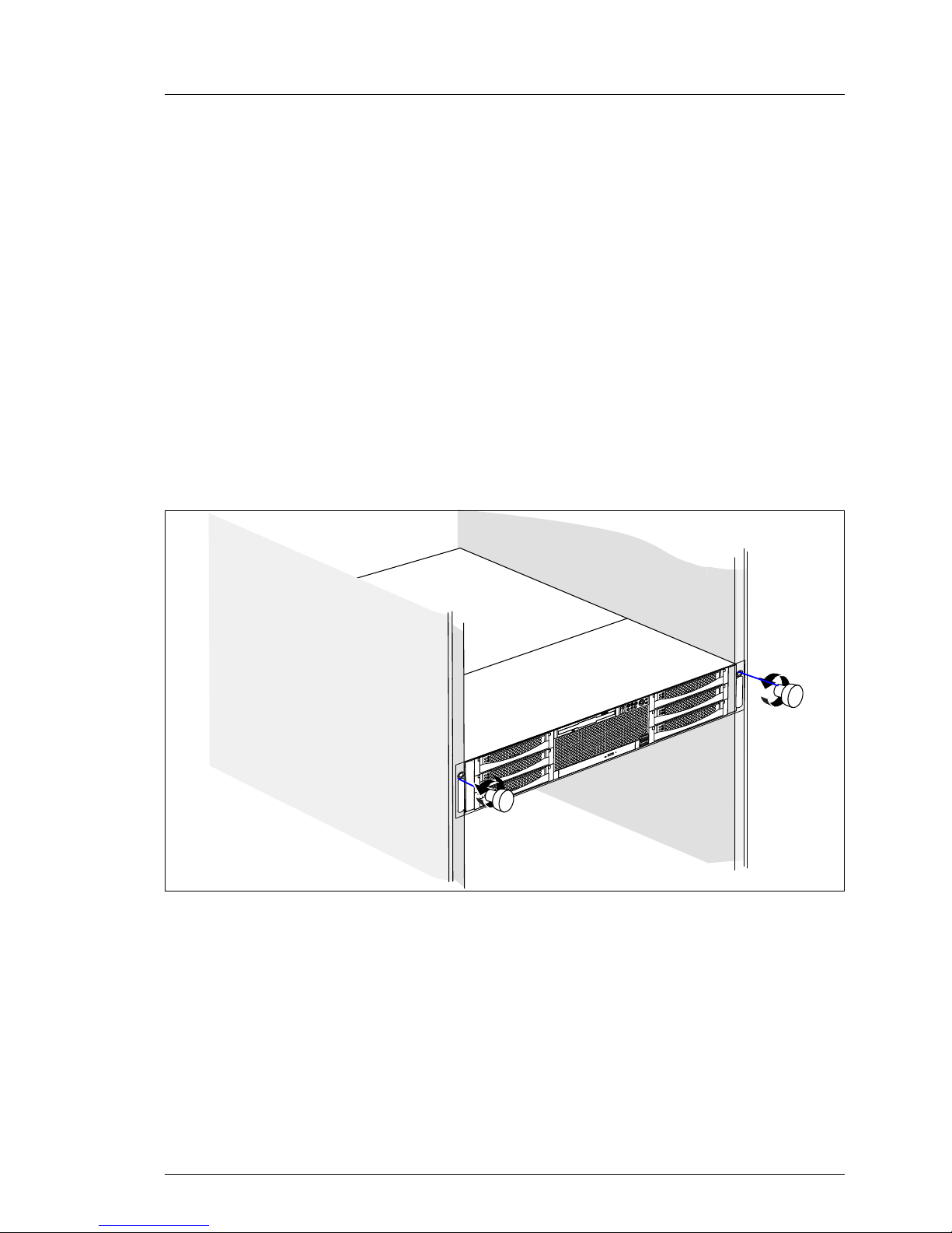
Figure 2: Loosening the knurled screws
Ê Loosen the four knurled screws (1) and pull the server as far as possible out
of the rack.
Page 22
22 Options Guide RX300 S3
Removing the server form the rack Preparation
Depending on how accessible the server is in the rack cabinet, it can make
sense to remove it from the cabinet. If you do not want to remove the server from
the rack cabinet, please skip this page.
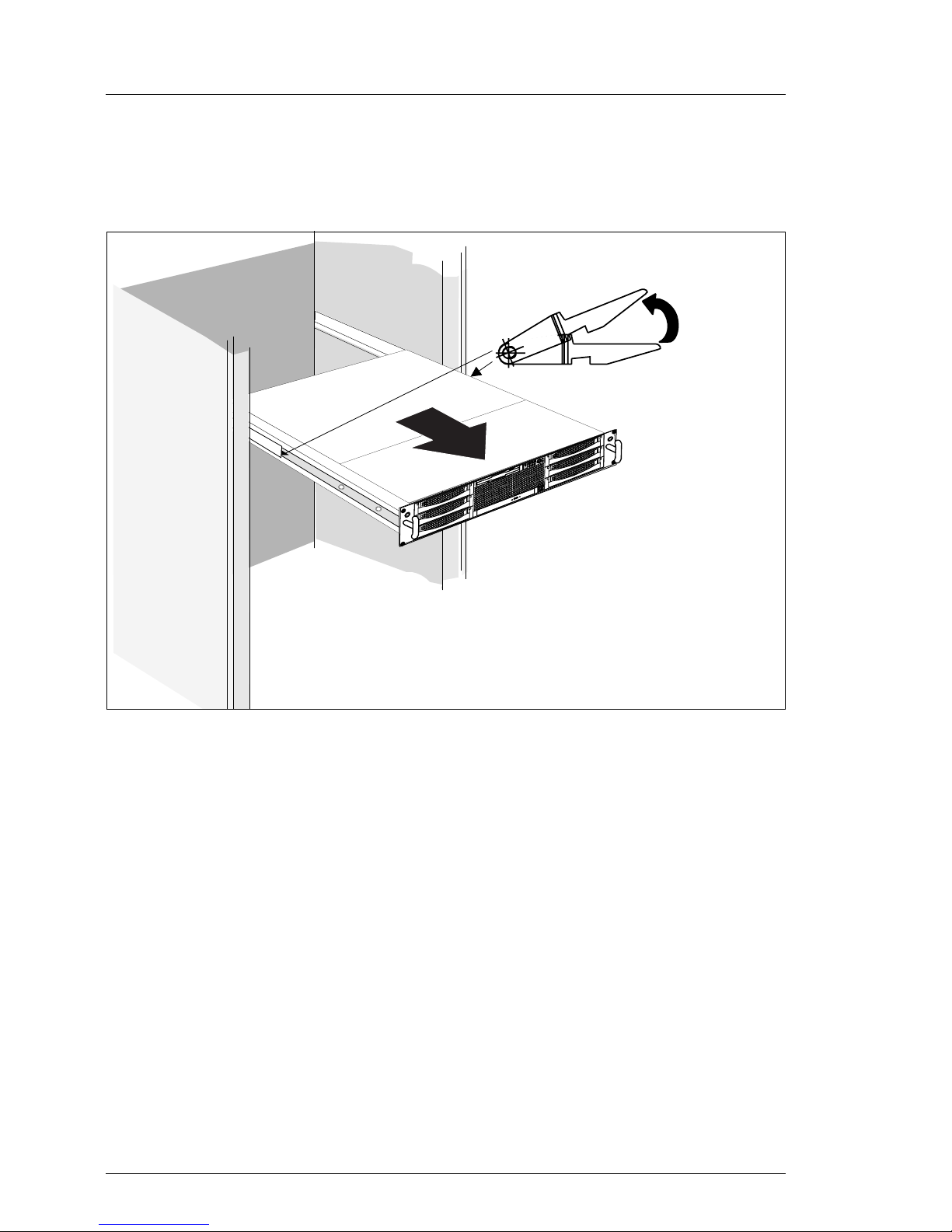
Figure 3: Removing the server from the rack cabinet
Ê Disconnect all cables on the rear of the server.
Ê Pull the server outward as far as it will go (1), release the hooks (2), then pull
out the Server completely.
V CAUTION!
At least two people are needed to lift the server out of the rack cabinet.
Page 23
RX300 S3 Options Guide 23
Preparation Opening the server
4.2 Opening the server
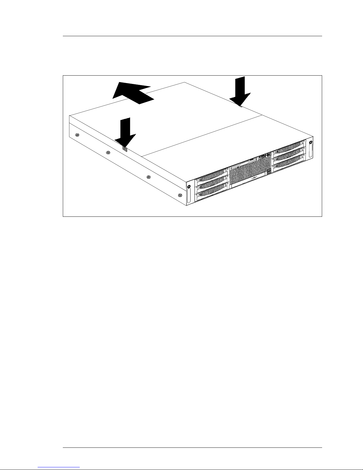
Figure 4: Removing the top cover
Ê Pess the two locking buttons (1) downward and remove the cover (2).
Ê Slide the cover to the rear side and remove it (2).
2
1
1
2
Page 24

Page 25
RX300 S3 Options Guide 25
5Main memory
V CAUTION!
Observe the safety instructions in the chapter “Safety notes” on page 15.
The system board supports up to 32 Gbytes of main memory. 8 slots (2 memory
banks with 4 slots each) are provided for the main memory. Each memory bank
is equipped with two 512-Mbyte, 1-Gbyte, 2-Gbyte or 4-Gbyte FBD533/PC24200F or FBD667/PC2-5300 Fully Buffered DIMM memory modules.
A memory bank can optionally be configured as a hot-spare bank.
ECC with memory scrubbing and with the Single Device Data Correction
(SDDC, Chipkill) function is standard.
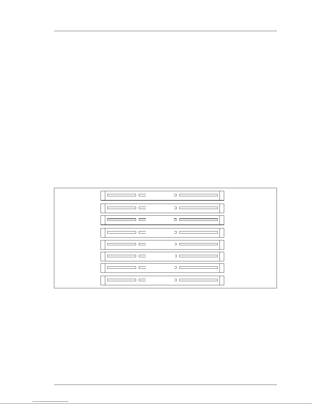
5.1 Memory module population
Figure 5: Structure of the main memory in memory banks and memory modules
– The memory modules have to be based on FBD533/PC2-4200F oder
FBD667/PC2-5300F Fully Buffered DIMM-Modules and must be populated
in pairs
– Each pair must consist of identical memory modules (2-way Interleaved-
mode).
– The memory module capacity can differ for the various memory banks: e.g.
memory bank 1A/1B can be equipped with two 512-Mbyte memory
modules, and memory bank 2A/2B with two 1-Gbyte memory modules.
DIMM-2C
DIMM-1C
DIMM-2B
DIMM-1B
DIMM-2A
DIMM-1A
DIMM-2D
DIMM-1D
Page 26
26 Options Guide RX300 S3
Memory module population Main memory
– Only single ranked modules are permitted.
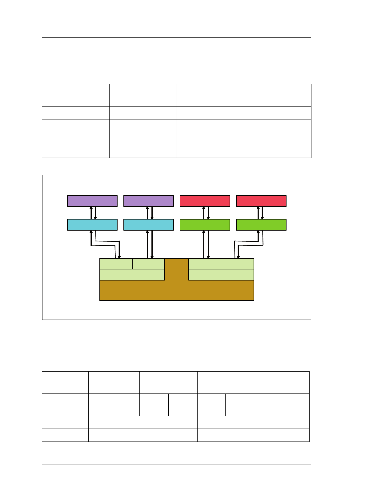
The following table shows the required memory population sequence:
Figure 6: Schema Memory Mirroring
Memory mirroring
Either 4 or 8 identical memory modules are required for memory mirroring:
Module pair
1A/1B
Module pair
1C/1D
Module pair
2A//2B
Module pair
2C/2D
populated empty empty empty
populated populated empty empty
populated populated populated empty
populated populated populated populated
Memory
bank
32 1 0
Channel
(module)
ABABABAB
population 4 identical memory modules - -
4 identical memory modules 4 identical memory modules
Memory Controlle
r
(Blackford M CH)
Channel
A
Branch 0
Channel B Channel C
Branch 1
Channel D
Bank 1
Bank 2
Bank 1
Bank 2
FB-DIM
M
FB-DIM
M
FB-DIM
M
FB-DIM
M
FB-DIM
M
FB-DIM
M
FB-DIM
M
FB-DIM
M
Memory Controlle
r
(Blackford M CH)
Channel
A
Branch 0
Channel BChannel
A
Branch 0
Channel B Channel C
Branch 1
Channel DChannelC
Branch 1
Channel D
Bank 1
Bank 2
Bank 1
Bank 2
FB-DIM
M
FB-DIM
M
FB-DIM
M
FB-DIM
M
FB-DIM
M
FB-DIM
M
FB-DIM
M
FB-DIM
M
Page 27
RX300 S3 Options Guide 27
Main memory Memory module population
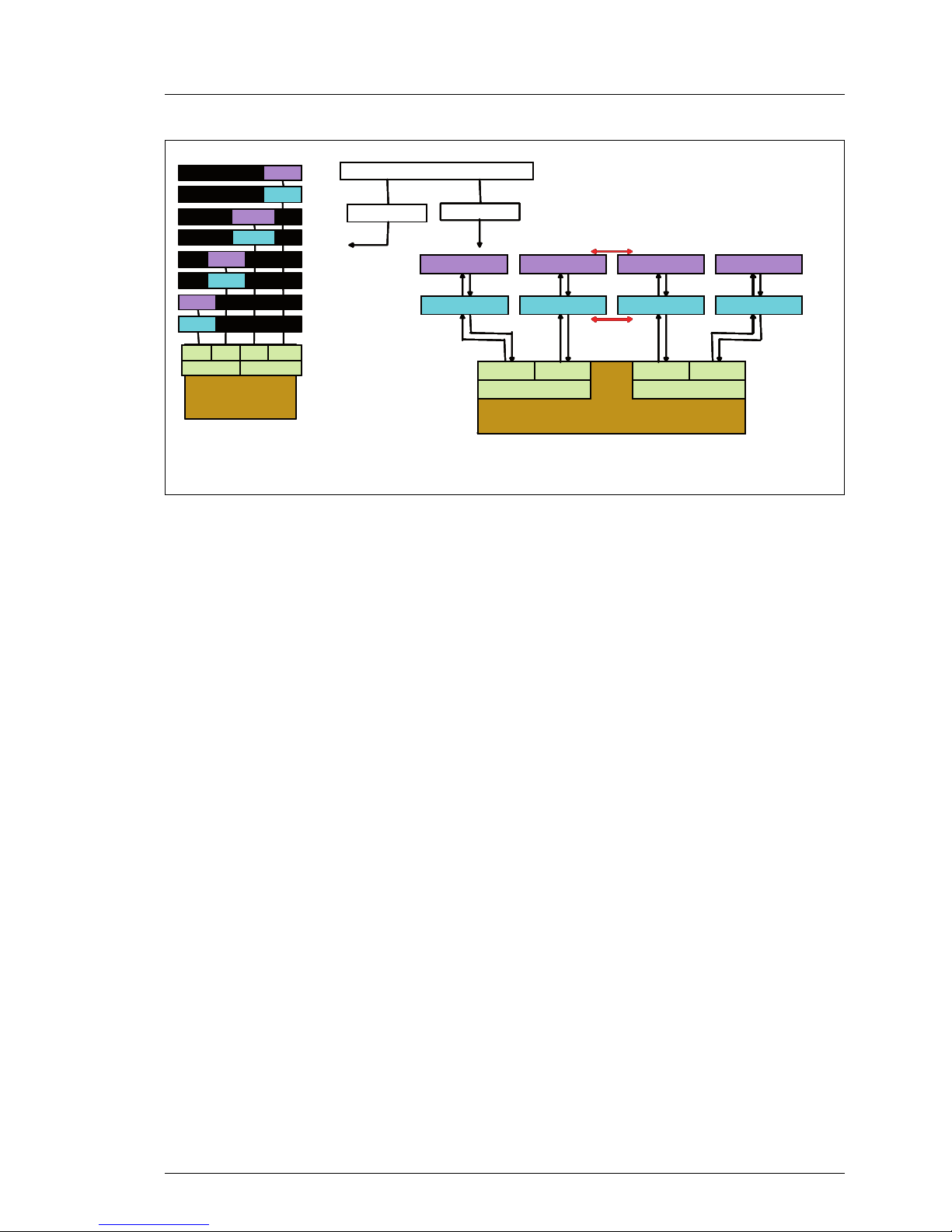
Figure 7: Diagram Memory Mirroring
I For more information see BIOS-Setup manual (see chapter “Related
publications” on page 117).
Logical View
P hysical View
Memory Population
Logical View
P hysical View
Memory Population
Memor
y
Controlle
r
(Blackford
MCH)
FB-DIMM
FB-DIMM
FB-DIMM
FB-DIMM
FB-DIMM
FB-DIMM
FB-DIMM
FBD 1A
FBD 2A
FBD 1B
FBD 2B
FBD 2C
FBD 2D
FBD 1C
FBD 1D
FB
-
DIMM
Memory Controller
(BlackfordMCH)
Channel 0
Branch 0
Channel 1
Channel 2
Branch 1
Channel 3
FB-DIMM
FB-DIMM ( Spare )
FB-DIMM
FB-DIMM ( Spare )
FB-DIMM
FB-DIMM ( Spare )
FB-DIMM
FB-DIMM ( Spare )
Memory Controller
(BlackfordMCH)
Channel 0
Branch 0
Channel 1
Channel A
Branch 0
Channel B
Channel 2
Branch 1
Channel 3
Channel C
Branch 1
Channel D
Bank 1
Bank 2
Bank 1
Bank 2
FB-DIMM
FB-DIMM
FB-DIMM
FB-DIMM
FB-DIMM (M )
FB-DIMM ( M )
FB-DIMM (M )
FB-DIMM ( M )
Mirroring
Mirroring
ChA
Branch 0
ChB Ch
C
Branch 1
Ch
D
Logical View
P hysical View
Memory Population
Logical View
P hysical View
Memory Population
Memor
y
Controlle
r
(Blackford
MCH)
FB-DIMM
FB-DIMM
FB-DIMM
FB-DIMM
FB-DIMM
FB-DIMM
FB-DIMM
FBD 1A
FBD 2A
FBD 1B
FBD 2B
FBD 2C
FBD 2D
FBD 1C
FBD 1D
FBD 1A
FBD 2A
FBD 1B
FBD 2B
FBD 2C
FBD 2D
FBD 1C
FBD 1D
FB
-
DIMM
Memory Controller
(BlackfordMCH)
Channel 0
Branch 0
Channel 1
Channel 0
Branch 0
Channel 1
Channel 2
Branch 1
Channel 3
Channel 2
Branch 1
Channel 3
FB-DIMM
FB-DIMM ( Spare )
FB-DIMM
FB-DIMM ( Spare )
FB-DIMM
FB-DIMM ( Spare )
FB-DIMM
FB-DIMM ( Spare )
Memory Controller
(BlackfordMCH)
Channel 0
Branch 0
Channel 1
Channel A
Branch 0
Channel B
Channel 2
Branch 1
Channel 3
Channel C
Branch 1
Channel D
Bank 1
Bank 2
Bank 1
Bank 2
FB-DIMM
FB-DIMM
FB-DIMM
FB-DIMM
FB-DIMM (M )
FB-DIMM ( M )
FB-DIMM (M )
FB-DIMM ( M )
Mirroring
Mirroring
ChA
Branch 0
ChB Ch
C
Branch 1
Ch
D
ChA
Branch 0
ChBChA
Branch 0
ChB Ch
C
Branch 1
Ch
D
Page 28
28 Options Guide RX300 S3
Upgrading/replacing the main memory Main memory
5.2 Upgrading/replacing the main memory
Ê Open the server as described in the chapter “Safety notes” on page 15.
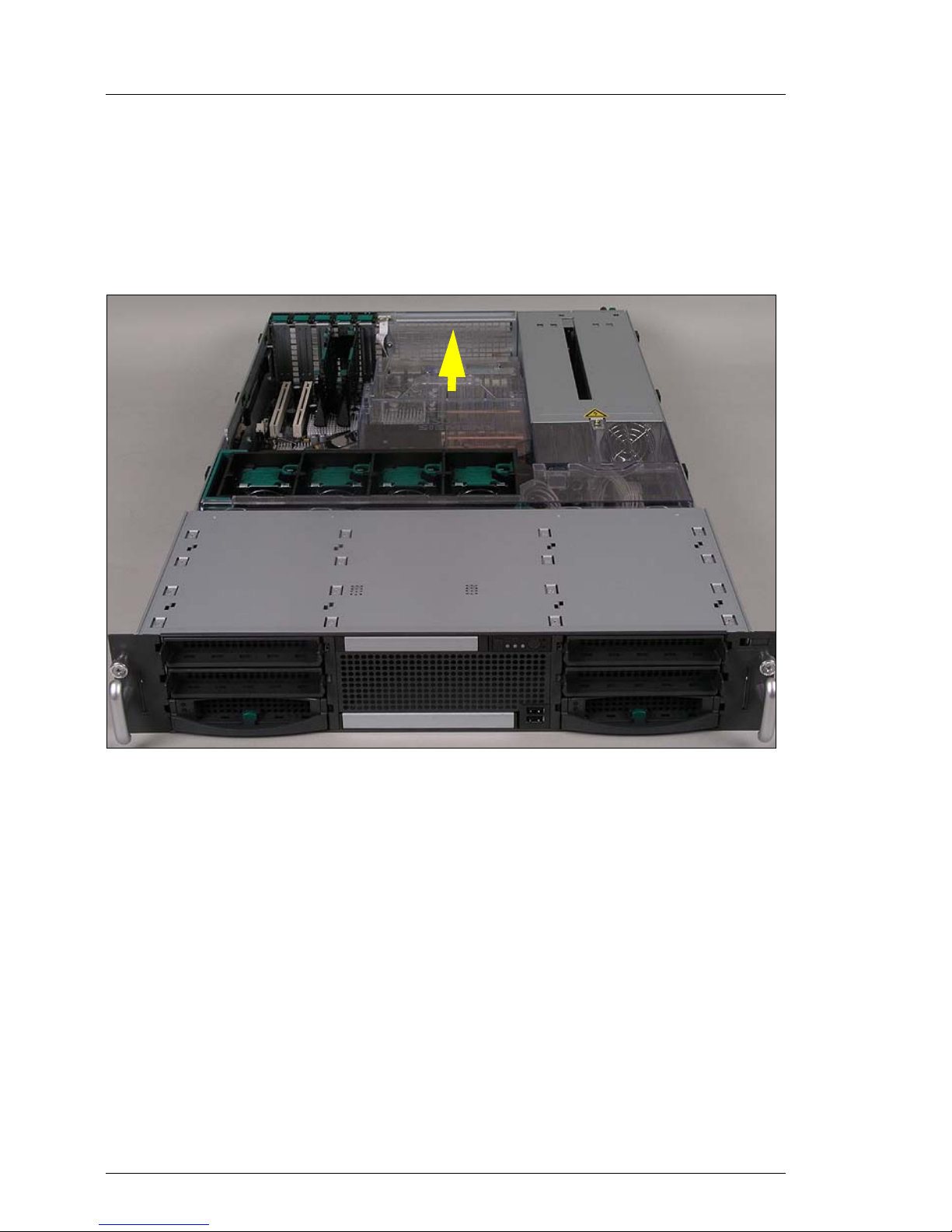
Removing the air duct over the main memory and the processors
Figure 8: Removing the air duct over the main memory and the processors
Ê Lift out the air duct over the main memory.
Page 29
RX300 S3 Options Guide 29
Main memory Upgrading/replacing the main memory
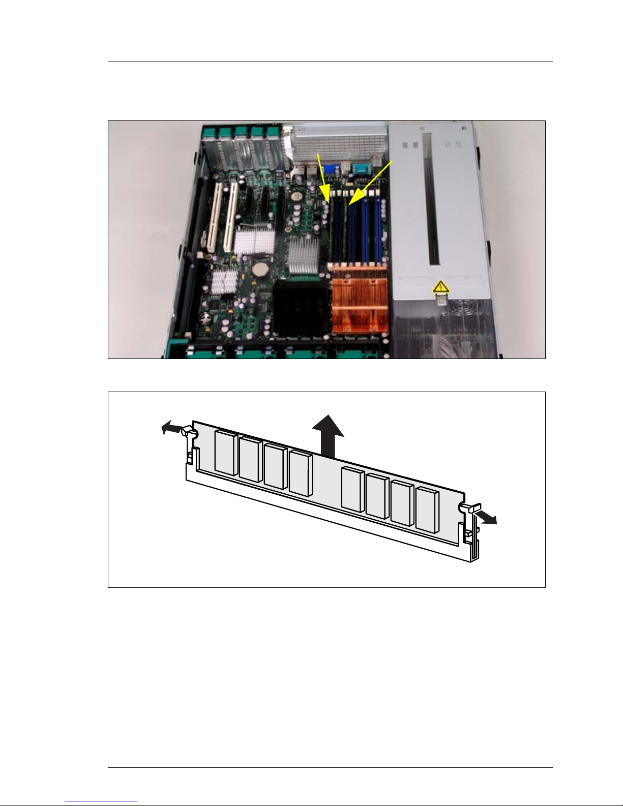
Installing mermorymodules
Figure 9: populating memory module slots
Figure 10: Removing a memory module
Ê Press the holders on either side of the mounting location concerned outward
(1).
Ê Pull the memory module out of the mounting location (2).
Page 30
30 Options Guide RX300 S3
Upgrading/replacing the main memory Main memory
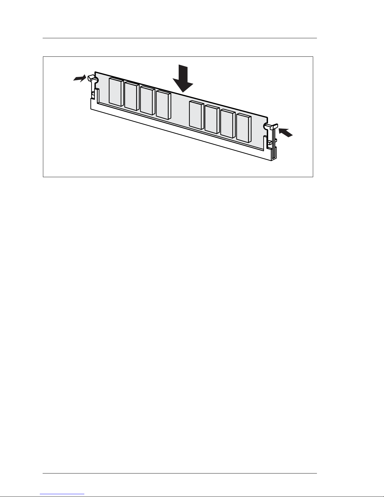
Figure 11: Inserting a memory module
Ê Press the holders on either side of the mounting location concerned
outward.
Ê Insert the memory module in the mounting location (1) until the holders at
the sides engage (2).
Page 31

RX300 S3 Options Guide 31
Main memory Upgrading/replacing the main memory
Inserting air duct
Figure 12: Installing the air duct over the memory and processors
Ê Reinstall the air duct over the memory and the processors.
Page 32

32 Options Guide RX300 S3
Upgrading/replacing the main memory Main memory
Figure 13: Installing of the air duct
V CAUTION
When you install the air duct take care of the heat sink fins and the
condensers in the marked area.
Make sure that the fins over the memory are not twisted and lie flat on
the memory
Ê Close the server, connect it to the power outlet, and switch it on as described
in the chapter “Completion” on page 101.
Page 33

RX300 S3 Options Guide 33
6 Processors
V CAUTION!
Observe the safety instructions in the chapter “Safety notes” on page 15.
V CAUTION!
Processors are modules which can react extremely sensitively to electrostatic discharges and which must therefore always be handled with care.
After a processor has been removed from its protective sleeve or from its
socket, place it with its smooth side down on a non-conducting, antistatic
surface. Never push a processor over a surface.
6.1 Installing a second processor
The system board can be upgraded with a second processor. The upgrade kit
consists of a processor, and a heat sink.
V CAUTION!
Only processors of the same type may be used on the system board. The
second processor must have the same clock frequency and the same
cache as the first processor. For dual operation, use a suitable multiprocessor operating system.
Ê Open the server as described in the chapter “Preparation” on page 21.
Ê Remove the air duct over the main memory (see chapter “Main memory” on
page 28).
Page 34

34 Options Guide RX300 S3
Installing a second processor Processors
Figure 14: Removing processor dummy module
Ê Pull the processor dummy out.
V CAUTION!
Keep the dummy cover for future use. If you remove the processor again
and do not replace it with a new one, reinstall the dummy cover to ensure
that the system is cooled properly.
Page 35

RX300 S3 Options Guide 35
Processors Installing a second processor
Figure 15: Empty processor slot
Ê Release the socket lever and pull it upward as far as it will go.
Ê Open the cover.
Figure 16: Opening the processor socket
Page 36

36 Options Guide RX300 S3
Installing a second processor Processors
Figure 17: Inserting the processor
Ê Position the new processor over the socket and then carefully press it into
the socket.
V CAUTION!
The processor can only be installed in one particular direction. Note
the marking on one of the corners. To avoid damaging the pins or the
processor, do not force it into the socket.
Ê Lock the processor in the socket by returning the socket lever to its original
position.
I When you close the the socket lever, the protective cover will
disengage itself.
Page 37

RX300 S3 Options Guide 37
Processors Installing a second processor
Figure 18: places of the springs round the heat sink support pins
Ê Check whether the springs round the heat sink support pins are aligned
centrally.
Ê Remove the protective cover on the underside of the heat sink.
Figure 19: Installing heat sink
Page 38

38 Options Guide RX300 S3
Replacing the processor Processors
Ê Place the heat sink on the processor.
Ê Fasten the heat sink by tightening the four screws in a crossover pattern.
V CAUTION!
Never install a processor without a heat sink as otherwise the processor
may overheat, causing a shut-down of the system.
Ê Reinstall the ventilation duct over the memory and processors.
V CAUTION!
Ensure a correct fit of the airduct and that no damage is caused to the
cables
Ê Close the server, connect it to the power outlet, and switch it on as described
in the chapter “Completion” on page 101.
6.2 Replacing the processor
V CAUTION
Only processors of the same type may be used on the system board. The
second processor must have the same clock frequency and the same
cache as the first processor. For dual operation, use a suitable multiprocessor operating system.
Ê Open the server as described in the chapter “Preparation” on page 21.
Ê Remove the air duct over the main memory (see chapter “Main memory” on
page 28).
Page 39

RX300 S3 Options Guide 39
Processors Replacing the processor
Figure 20: Removing the heat sink
Ê Loosen the four screws in a crossover pattern.
Ê Loosen the heat sink by turning it back and forth and then lift it out.
Page 40

40 Options Guide RX300 S3
Replacing the processor Processors
Figure 21: Removing the processor
Ê Release the socket lever and pull it upward as far as it will go.
Ê Carefully remove the installed processor .
2
1
Page 41

RX300 S3 Options Guide 41
Processors Replacing the processor
Figure 22: Inserting a new processor
Ê Position the new processor over the socket and then carefully press it into
the socket (1).
V CAUTION!
The processor can only be installed in one particular direction. Note
the marking on one of the corners (2). To avoid damaging the pins or
the processor, do not force it into the socket.
Ê Lock the processor in place in the socket by returning the socket lever to its
original position (3).
Ê Remove the protective cover on the underside of the heat sink. Do not touch
the pad.
Ê Place the heat sink on the processor socket (see figure 19 on page 37).
Ê Fasten the heat sink by tightening the four screws in a crossover pattern.
Ê Reinstall the air duct over the main memory and the processors (see
“Inserting air duct” on page 31).
Ê Close the server, connect it to the power outlet, and switch it on as described
in the chapter “Completion” on page 101.
Page 42

42 Options Guide RX300 S3
Replacing the processor heat sink Processors
6.3 Replacing the processor heat sink
Ê Open the server as described in section “Opening the server” on page 23.
Ê Remove the air duct over the main memory and the processors (see section
“Upgrading/replacing the main memory” on page 28).
Ê Loosen the four heat sink screws in a crossover pattern (see section
“Replacing the processor” on page 38).
Ê Loosen the heat sink by turning it back and forth and then lift it out.
Ê Clean the upper side of the processor using a lint-free cloth.
Ê Remove the protective cover from the new heat sink.
Ê Place the heat sink on the processor socket (see section “Replacing the
processor” on page 38).
Ê Fasten the heat sink by tightening the four screws in a crossover pattern.
Ê Reinstall the air duct over the main memory and the processors (see section
“Upgrading/replacing the main memory” on page 28).
Page 43

RX300 S3 Options Guide 43
7 ROMB (RAID on Motherboard)
V CAUTION!
Observe the safety instructions in the chapter “Safety notes” on page 15.
The on-board SAS controller can be upgraded to a RAID5 (RAID 0, 1, 5, 10, 50)
controller with a "MegaRaid PCI Express™ ROMB" upgrade kit. In this case the
on-board INTEL I/O processor is activated by installing a license key and a
cache module.
Two different upgrade kits are offered:
– Upgrade kit S26361-F3205-E256, consisting of an iButton license key and a
256 MB cache module.
– Upgrade kit S26361-F3205-E556, consisting of an iButton license key and a
256 MB cache module with a battery also integrated on the module (iTBBU=
integrated Transportable Battery Backup Unit).
7.1 Installing the ROMB upgrade kit
Ê Open the server as described in the chapter “Preparation” on page 21.
Page 44

44 Options Guide RX300 S3
Installing the ROMB upgrade kit ROMB (RAID on Motherboard)
Figure 23: Cache module (with battery) and iButton
Ê Connect the cable on the module.
Figure 24: Installing the iButton and the Cache module
Ê Install the iButton on the system board (1).
1
Page 45

RX300 S3 Options Guide 45
ROMB (RAID on Motherboard) Installing the ROMB upgrade kit
Ê Press the holders on either side of the mounting location outward.
Figure 25: iButton und Cache Modul einsetzen
Ê Insert the cache module.
Ê Press the cache module downward until the holders on either side of the
mounting location are engaged.
Ê Close the server, connect it to the power outlet, and switch it on as described
in the chapter “Completion” on page 101.
I Information on the configuration is provided in the Technical Manual for
the system board.
Page 46

Page 47

RX300 S3 Options Guide 47
8 Accessible drives
V CAUTION!
Observe the safety instructions in the chapter “Safety notes” on page 15.
I Two free bays are available for accessible drives. One 3,5 Inch x 0,5 Inch
is for a FD drive and one 5,25 inch x 0,5 inch is for a CD/DVD-ROM drive
available. A local view module can also be installed Into the upper bay
(FD drive).
V CAUTION!
For installing a FD drive or a CD-/DVD drive frames and cables are
necessary.
Page 48

48 Options Guide RX300 S3
Installing a FD drive Accessible drives
8.1 Installing a FD drive
Ê Open the server as described in the chapter “Preparation” on page 21.
Removing cover
Figure 26: Cover in front of fanbox
Ê Disengage the cover.
Ê Remove the cover.
Page 49

RX300 S3 Options Guide 49
Accessible drives Installing a FD drive
Removing a FD drive dummy module
Figure 27: Unlocking the FD drive dummy module
Ê Unlock the FD drive dummy module (1).
Ê Push the FD drive dummy module to the front (2).
Figure 28: Removing dummy module
Ê Pull the FD drive dummy module out to the front side.
1
2
Page 50

50 Options Guide RX300 S3
Installing a FD drive Accessible drives
V CAUTION!
Keep the dummy module for future use. If you remove the FD drive
again and do not replace it with a new one, the dummy module must
be reinstalled to comply with EMC regulations and to satisfy cooling
requirements and fire protection measures.
Installing FD drive
Figure 29: Insert FD drive into the mounting frame.
I The mouning frame and the cable is deliverd in the accessory pack with
the PRIMERGY RX300 S2.
Ê Insert the FD drive into the mounting frame. Regard the plastic pins. They fix
the dive in the frame.
Page 51

RX300 S3 Options Guide 51
Accessible drives Installing a FD drive
Figure 30: connect the FDD-cable
Ê Connect the cable as shown in the photo.
I Install the cable so, that the blue side shows to the lockingmechanism
of the connector of the drive.
Ê Thread the cable through the mounting frame.
Page 52

52 Options Guide RX300 S3
Installing a FD drive Accessible drives
Figure 31: Inserting FD drive module
Ê Thread the flat cable in the bay.
Ê Push the FD drive module into the bay, until it locks.
Figure 32: Connecting FD drive cable
Ê Connect the FDD cable to the system board.
Ê Reinstall the cover again.
Ê Close the server, connect it to the power outlet, and switch it on as described
in the chapter “Completion” on page 101.
Page 53

RX300 S3 Options Guide 53
Accessible drives Installing a LocalView module
8.2 Installing a LocalView module
The LocalView module is an optional extra for the servers of the PRIMERGY
series. On the display panel of the LocalView module you can read status
messages directly on the server. These status messages provide information on
the system and notify you of hardware faults (e.g. fan failure, CPU over voltage,
etc.).
The LocalView module can be pulled out like a sliding drawer. You can also
angle the LocalView display panel downward.
The LocalView module can be installed in the 3,5/0,5 inch bay of the FD drive.
Figure 33: LocalView module
Ê Open the server as described in the chapter “Preparation” on page 21.
Ê remove the cover (see “Removing cover” on page 48)
Ê If a FDD-dummy module is installed it must be removed (see “Removing a
FD drive dummy module” on page 49).
Page 54

54 Options Guide RX300 S3
Installing a LocalView module Accessible drives
Removing the FD Drive
Figure 34: Unlocking the the FD Drive module (for better visibility, the fanbox is removed)
Ê Unlock (1) the FDD module.
Ê Push the FDD module to the front (2).
Ê Remove the FD drive cable from the system board.
Figure 35: Removing FD-Drive module
Ê Pull the FD drive module out. to the front side.
1
2
Page 55

RX300 S3 Options Guide 55
Accessible drives Installing a LocalView module
Figure 36: Cable out of cable clamp
Ê Take out the cable for the LocalView module from the cable clamp and
thread the cable through the bay to the front side.
I This cable has a red marking. Do not mistake the SMB cable for the
power cable optical drives.
Figure 37: Connecting the cable to the LocalView module
Page 56

56 Options Guide RX300 S3
Installing a LocalView module Accessible drives
Ê Connect the cable to the LocalView module.
Figure 38: Inserting the LocalView module
Ê Slide the LocalView module into the mounting location until it latches in
place.
I Further information on operation and display modes is provided in the
documentation for the LocalView module.
Ê Reinstall the cover again.
Ê Close the server, connect it to the power outlet, and switch it on as described
in the chapter “Completion” on page 101.
Page 57

RX300 S3 Options Guide 57
Accessible drives Installing the CD/ DVD-ROM drive
8.3 Installing the CD/ DVD-ROM drive
Ê Open the server as described in the chapter “Preparation” on page 21.
Ê Remove the cover (see “Removing cover” on page 48)
Removing the CD/DVD drive dummy module
Figure 39: Unlocking the CD drive dummy module
Ê Unlock (1) the CD/DVD drive dummy module.
Ê Push the CD/DVD module to the front (2) out by the retention mechanism
and take out the CD/DVD module frontward (3).
1
3
2
Page 58

58 Options Guide RX300 S3
Installing the CD/ DVD-ROM drive Accessible drives
Figure 40: Removing dummy module with mounting frame
Ê Remove the dummy module.
V CAUTION!
Keep the dummy module for future use. If you remove the accessible
drive again and do not replace it with a new one, the dummy module must
be reinstalled to comply with EMC regulations and to satisfy cooling
requirements and fire protection measures.
Ê Remove the dummy module from the mounting frame
Page 59

RX300 S3 Options Guide 59
Accessible drives Installing the CD/ DVD-ROM drive
Figure 41: Installing CD/ DVD Laufwerk in the mounting frame
Ê Install the CD/DVD Drive in the mounting frame Regard the plastic pins
which fix the drive in the frame.
Figure 42: Connecting the CD/DVD drive cables
Ê Thread the power cable (1) through the bay and connect it to the CD Drive
(see also chapter “Appendix” on page 105).
Page 60

60 Options Guide RX300 S3
Tape drive Accessible drives
I The power cable has no red marking.Do not mistake the power cable
for the SMB cable for the LocalView.
Ê Connect the IDE cable to the drive (see also chapter “Appendix” on
page 105)
Figure 43: Pushing the CD/DVD drive into the bay
Ê Push the drive into the bay completely.
Ê Reinstall the cover again.
Ê Close the server, connect it to the power outlet, and switch it on as described
in the chapter “Completion” on page 101.
8.4 Tape drive
I The Installtion of a tape drive ist only possible for the 3,5“ HDD version.
Ê Open the server as described in the chapter “Preparation” on page 21.
Page 61

RX300 S3 Options Guide 61
Accessible drives Tape drive
Ê Remove the cover (see “Removing cover” on page 48).
Figure 44: Push USB tapedrive into the mounting carrier
Ê Push the tape drive into the mounting carrier.
Ê Insert the screws on the right and left side.
Figure 45: Installing the USB tape drive
Page 62

62 Options Guide RX300 S3
Tape drive Accessible drives
Ê Thread the USB cable and the power cable through the duct to the front.
Figure 46: rear side of the tape drive
Ê Connect the USB cable (1) to the rear side of the tape drive
Ê Connect the power cable (2) to the rear side of the tape drive
Figure 47: USB Magnetbandlaufwerk einbauen
12
Page 63

RX300 S3 Options Guide 63
Accessible drives Tape drive
Ê Push the tape drive in.
Ê When pushing the drive into place pull the cables back so that they are not
pinched
Ê Lock the drive.
I The front of the drive projects approx. 5mm beyond the front of the
server.
Figure 48: Connecting USB cable to the system board
Ê Connect the power cableto the SAS backplane
Ê Connect the USB Cable to the USB7 connector on the system board.
Ê Insert the cover.
Ê Close the server, connect it to the power outlet, and switch it on as described
in the chapter “Completion” on page 101.
Page 64

Page 65

RX300 S3 Options Guide 65
9PCI slots
V CAUTION!
Observe the safety instructions in the chapter “Safety notes” on page 15.
Standard configuration
The system board offers five PCI slots. Slots 1, 2 and 5 are non-hot-plug PCI
slots .
I The PCI slot 3 and 4 are hot-plug slots, that can be equipped with hot-
plug controllers. You will find the description of the hot-plug slots in the
Operating Manual.
Optional configuration with riser card
Three standard slots are available with a riser card: 1 x PCI-X 64-bit/100 MHz,
long, standard height; 2 x PCI-X 64-bit/100 MHz, short, standard height.
Page 66

66 Options Guide RX300 S3
Installing a PCI controller in a low-profile slot PCI slots
9.1 Installing a PCI controller in a low-profile
slot
Ê Open the server as described in the chapter “Preparation” on page 21.
Figure 49: Remove the slot cover
Ê Push the green PCI board holder toward the rear (1).
Ê Remove the slot cover of the PCI slot (2).
V CAUTION!
Keep the rear cover of the PCI slot for future use. If you remove the
controller again and do not replace it with a new one, the rear cover
must be reinstalled to comply with EMC regulations and to satisfy
cooling requirements and fire protection measures.
1
2
Page 67

RX300 S3 Options Guide 67
PCI slots Installing a PCI controller in a low-profile slot
Figure 50: Inserting controller
Ê Install the controller in the PCI slot and press it carefully into the associated
plug-in location on the system board (1). Ensure that the rear cover fits into
the recesses (a).
Ê Close the green PCI board holder (2).
Ê If required, connect the cables to the controller and other components.
Ê Close the server, connect it to the power outlet, and switch it on as described
in the chapter “Completion” on page 101.
a
a
1
2
Page 68

68 Options Guide RX300 S3
Installing the PCI controller in the riser card PCI slots
9.2 Installing the PCI controller in the riser card
Ê Open the server as described in the chapter “Preparation” on page 21.
Figure 51: Removing the riser card
Ê Open the knurled screws.
V CAUTION!
Keep the rear cover of the PCI slot for future use. If you remove the
controller again and do not replace it with a new one, the rear cover
must be reinstalled to comply with EMC regulations and to satisfy
cooling requirements and fire protection measures.
Page 69

RX300 S3 Options Guide 69
PCI slots Installing the PCI controller in the riser card
Figure 52: Removing the riser card
Ê Remove the riser card upward.
I Hold the riser by the latch (A).
A
Page 70

70 Options Guide RX300 S3
Installing the PCI controller in the riser card PCI slots
Figure 53: Installing the controller
Ê Press on the locking mechanism of the cover.
Ê Open the locking mechanism.
Page 71

RX300 S3 Options Guide 71
PCI slots Installing the PCI controller in the riser card
Figure 54: Installing controller
Ê Remove the slot cover of the requested slot.
Page 72

72 Options Guide RX300 S3
Installing the PCI controller in the riser card PCI slots
Figure 55: Installing Controller
Ê Insert the controller into the PCI slot and push it down carefully.
Ê Close the cover.
Page 73

RX300 S3 Options Guide 73
PCI slots Installing the PCI controller in the riser card
Figure 56: Installed Controller
Ê If necessary connect the cables to the controller or other components.
Ê Insert the riser card and be careful with the cables.
I Take care that the latch is engaged in the side panel.
Ê Close the server, connect it to the power outlet, and switch it on as described
in the chapter “Completion” on page 101.
Page 74

Page 75

RX300 S3 Options Guide 75
10 External serial interface
V CAUTION!
Observe the safety instructions in the chapter “Safety notes” on page 15.
10.1 Installing the external serial interface
Ê Open the server as described in the chapter “Preparation” on page 21.
I For standard configuration the external serial interface is to install with a
low profile slot cover. If the optional riser card is used, a standard slot
cover is necessary.
External serial interface in standard configuration
Figure 57: External serial cable with low-profile slot cover.
Ê Remove slot cover 5 ( see “Remove the slot cover” on page 66)
Page 76

76 Options Guide RX300 S3
Installing the external serial interface External serial interface
Figure 58: Installing external serial cable
Ê Insert the slot cover.
Ê Lock the the slot cover.
Ê Route the serial cable, as shown in the picture.
Ê Close the server, connect it to the power outlet, and switch it on as described
in the chapter “Completion” on page 101.
Page 77

RX300 S3 Options Guide 77
External serial interface Installing the external serial interface
External SCSI interface in the riser
Figure 59: External serial interface with standart slot
Ê Insert the SCSI connector to the slot cover.
Figure 60: Remove riser
Ê Remove the riser.
Page 78

78 Options Guide RX300 S3
Installing the external serial interface External serial interface
Figure 61: Removing slot cover from slot 6
Ê Open the cover.
Ê Remove the slot cover of slot 8.
Page 79

RX300 S3 Options Guide 79
External serial interface Installing the external serial interface
Figure 62: External serial interface
Ê Insert the slot cover with the serial interface in slot 8.
Ê Close the cover.
Page 80

80 Options Guide RX300 S3
Installing the external serial interface External serial interface
Figure 63: Thread external cable
Ê Thread the cable through the cutout.
Figure 64: Inserting the riser
Ê Insert the riser.
Page 81

RX300 S3 Options Guide 81
External serial interface Installing the external serial interface
Ê Connect the external serial cable to the system board (see arrow).
Ê Fix the riser with the two screws.
Figure 65: Connecting the external SCSI cable to the system board
Ê Route the cable as shown.
Ê Close the server, connect it to the power outlet, and switch it on as described
in the chapter “Completion” on page 101.
I If another external parallel interface is to be installed in addition to the
external serial interface, route the cables as shown in the next step.
The serial interface is then installed in slot 7 and the parallel interface in
slot 8.
Page 82

82 Options Guide RX300 S3
Installing the external serial interface External serial interface
Figure 66: External serial and parallel interface
Ê Route the both cables as shown in the picture.
Ê Close the server, connect it to the power outlet, and switch it on as described
in the chapter “Completion” on page 101.
Page 83

RX300 S3 Options Guide 83
11 Parallel interface
V CAUTION!
Observe the safety instructions in the chapter “Safety notes” on page 15.
11.1 Installing a parallel interface
Ê Open the server as described in the chapter “Preparation” on page 21.
I For standard configuration the parallel interface is to install into a low-
profile slot cover. If the optional riser board is used, a standard slot cover
is necessary.
Parallel interface in standard configuration
Figure 67: external parallel interface with low-profile slot cover
Ê Remove slot cover 5 ( see “Remove the slot cover” on page 66)
Page 84

84 Options Guide RX300 S3
Installing a parallel interface Parallel interface
Figure 68: Routing the cable
Ê Insert the slot cover with the parallel interface.
Ê Connect the cable to the system board (see arrow).
Ê Route the cable as shown in the picture directly upon the system board.
Ê Close the server, connect it to the power outlet, and switch it on as described
in the chapter “Completion” on page 101.
Page 85

RX300 S3 Options Guide 85
Parallel interface Installing a parallel interface
External Parallel-interface in slot cover with standard height
Figure 69: External parallel interface with standard slot cover
Ê Insert the connector of the parallel interface in the slot cover.
Figure 70: Removing the riser
Ê Remove the riser.
Page 86

86 Options Guide RX300 S3
Installing a parallel interface Parallel interface
Figure 71: Removing the slot cover of slot 8
Ê Remove the slot cover of slot 8.
Page 87

RX300 S3 Options Guide 87
Parallel interface Installing a parallel interface
Figure 72: Instelling the slot cover with the connector of ther parallel interface
Ê Insert the slot cover with the parallel interface in slot 8.
Page 88

88 Options Guide RX300 S3
Installing a parallel interface Parallel interface
Figure 73: Install the slot cover with a parallel interface
Ê Thread the flat cable between the riser board and the plastic side cover.
I Route the cable as shown in the photo.
Page 89

RX300 S3 Options Guide 89
Parallel interface Installing a parallel interface
Figure 74: Installing the riser with parallel interface.
Ê Insert the riser.
Ê Route the cable.
Ê Connect the cable to the system board.
Ê Close the server, connect it to the power outlet, and switch it on as described
in the chapter “Completion” on page 101.
Page 90

Page 91

RX300 S3 Options Guide 91
12 Converting from low-profile to
standard PCI Slots
V CAUTION!
Observe the safety instructions in the chapter “Safety notes” on page 15.
12.1 Removing lp slot cage
Ê Open the server as described in the chapter “Preparation” on page 21.
Figure 75: Removing hot-plug cable
Ê Release and remove the hot-plug cable from the system board.
Page 92

92 Options Guide RX300 S3
Removing lp slot cage Converting from low-profile to standard PCI Slots
Figure 76: Removing the slot cage
Ê Remove the two screws.
Ê Pull the slot cage out.
Figure 77: Without slot cage
Ê Equip the riser card as described in part “Installing the PCI controller in the
riser card” on page 68.
Page 93

RX300 S3 Options Guide 93
Converting from low-profile to standard PCI Slots Removing lp slot cage
Figure 78: Assembled Riser card
Page 94

94 Options Guide RX300 S3
Converting the air duct Converting from low-profile to standard PCI Slots
12.2 Converting the air duct
Figure 79: Removing cover
Ê Push the cover up.
Page 95

RX300 S3 Options Guide 95
Converting from low-profile to standard PCI Slots Converting the air duct
Figure 80: Cover removed
Figure 81: Installing cover
Page 96

96 Options Guide RX300 S3
Converting the air duct Converting from low-profile to standard PCI Slots
Ê Push the cover int the guides on the uppper side of the air duct.
Figure 82: converted air duct for riser
Page 97

RX300 S3 Options Guide 97
Converting from low-profile to standard PCI Slots Converting the air duct
Figure 83: Installing the air duct
Ê Insert the air duct.
I When you install the air duct take care of teh heat sink fins and the
condenser in the marked area.
Page 98

98 Options Guide RX300 S3
Installing the riser Converting from low-profile to standard PCI Slots
12.3 Installing the riser
Figure 84: Inserting the riser
Ê Install the riser.
Page 99

RX300 S3 Options Guide 99
Converting from low-profile to standard PCI Slots Installing the riser
Figure 85: With riser
Ê Press the riser firmly in place.
I Take care that the latch is engaged in the side panel.
Ê Tighten the two screws.
Ê Close the server, connect it to the power outlet, and switch it on as described
in the chapter “Completion” on page 101.
Page 100

 Loading...