

Page 1

PRIMERGY
PRIMERGY RX220
Server System
Service Supplement
Joachim Pichol
Fujitsu Siemens Computers GmbH Paderborn
81730 Munich
e-mail: email: manuals@fujitsu-siemens.com
Tel.: (052 51) 8-14884
Fax: (++49) 700 / 372 00000
RX220
Sprachen: En
Edition January 2006
Page 2

Comments… Suggestions… Corrections…
The User Documentation Department would like to
know your opinion of this manual. Your feedback helps
us optimize our documentation to suit your individual
needs.
Fax forms for sending us your comments are included in
the back of the manual.
There you will also find the addresses of the relevant
User Documentation Department.
Certified documentation
according to DIN EN ISO 9001:2000
To ensure a consistently high quality standard and
user-friendliness, this documentation was created to
meet the regulations of a quality management system
which complies with the requirements of the standard
DIN EN ISO 9001:2000.
cognitas. Gesellschaft für Technik-Dokumentation mbH
www.cognitas.de
Copyright and Trademarks
Copyright © 2006 Fujitsu Siemens Computers GmbH.
All rights reserved.
Delivery subject to availability; right of technical modifications reserved.
All hardware and software names used are trademarks of their respective manufacturers.
Page 3

Contents
1 Introduction . . . . . . . . . . . . . . . . . . . . . . . . . . . 5
1.1 Overview of the documentation . . . . . . . . . . . . . . . . . . 5
1.2 Notational conventions . . . . . . . . . . . . . . . . . . . . . . 7
2 Procedure . . . . . . . . . . . . . . . . . . . . . . . . . . . . 9
3 Safety notes . . . . . . . . . . . . . . . . . . . . . . . . . . 11
4 Replacement routines . . . . . . . . . . . . . . . . . . . . . 17
4.1 Preparation . . . . . . . . . . . . . . . . . . . . . . . . . . . 17
4.1.1 Opening/closing the server . . . . . . . . . . . . . . . . . . . 17
4.2 Replacing the fans . . . . . . . . . . . . . . . . . . . . . . . . 19
4.3 Replacing the control panel board . . . . . . . . . . . . . . . 25
4.4 Replacing the power supply unit . . . . . . . . . . . . . . . . 27
4.5 Replacing the internal server power supply cable . . . . . . . . 31
4.6 Replacing the chassis ID module . . . . . . . . . . . . . . . . 33
4.7 Replacing the non-hot-plug hard disk . . . . . . . . . . . . . . 34
4.8 Replacing the SATA backplane . . . . . . . . . . . . . . . . . 36
4.9 Replacing the fan backplane . . . . . . . . . . . . . . . . . . 37
4.10 Replacing the system board . . . . . . . . . . . . . . . . . . . 38
5 Appendix . . . . . . . . . . . . . . . . . . . . . . . . . . . . 41
5.1 Board layout . . . . . . . . . . . . . . . . . . . . . . . . . . . 41
5.1.1 Control panel board . . . . . . . . . . . . . . . . . . . . . . . 41
5.1.2 SATA backplane . . . . . . . . . . . . . . . . . . . . . . . . . 42
5.1.3 Fan backplane . . . . . . . . . . . . . . . . . . . . . . . . . . 43
5.2 Cabling . . . . . . . . . . . . . . . . . . . . . . . . . . . . . 44
5.2.1 Cable overview . . . . . . . . . . . . . . . . . . . . . . . . . 44
5.2.2 Cable layout . . . . . . . . . . . . . . . . . . . . . . . . . . . 45
Index . . . . . . . . . . . . . . . . . . . . . . . . . . . . . . . . . . . . 47
RX220 Service Supplement
Page 4

Page 5

1Introduction
The PRIMERGY RX220 is an AMD-based server for mid-tier applications in
server farms. The server is well suited for front end services as well as for use
as an e-mail server, Internet server, or general applications server.
1.1 Overview of the documentation
Concept and target groups
This Service Supplement adds to the information provided in the Operating
Manual, the Options Guide and the Technical Manual for the system board.
V CAUTION!
The activities described in this manual may only be performed by service
personnel.
Service DVD
A service DVD PRIMERGY is available for Fujitsu Siemens service partners.
This DVD contains the following manuals as PDF files:
– The “Safety” manual
– The Operating Manual for the PRIMERGY RX220
– The Technical Manual for the system board D2130
– The Options Guide for the PRIMERGY RX220
– The “D2130 Setup Utility for RX220” manual
– The Service Supplement for the PRIMERGY RX220
I These PDF files (except the Service Supplement) can also be
downloaded free of charge from the Internet:
At http://manuals.fujitsu-siemens.com you will find an overview page
showing the online documentation available on the Internet. You can go
to the PRIMERGY Server documentation by clicking on industry standard
servers.
RX220 Service Supplement 5
Page 6
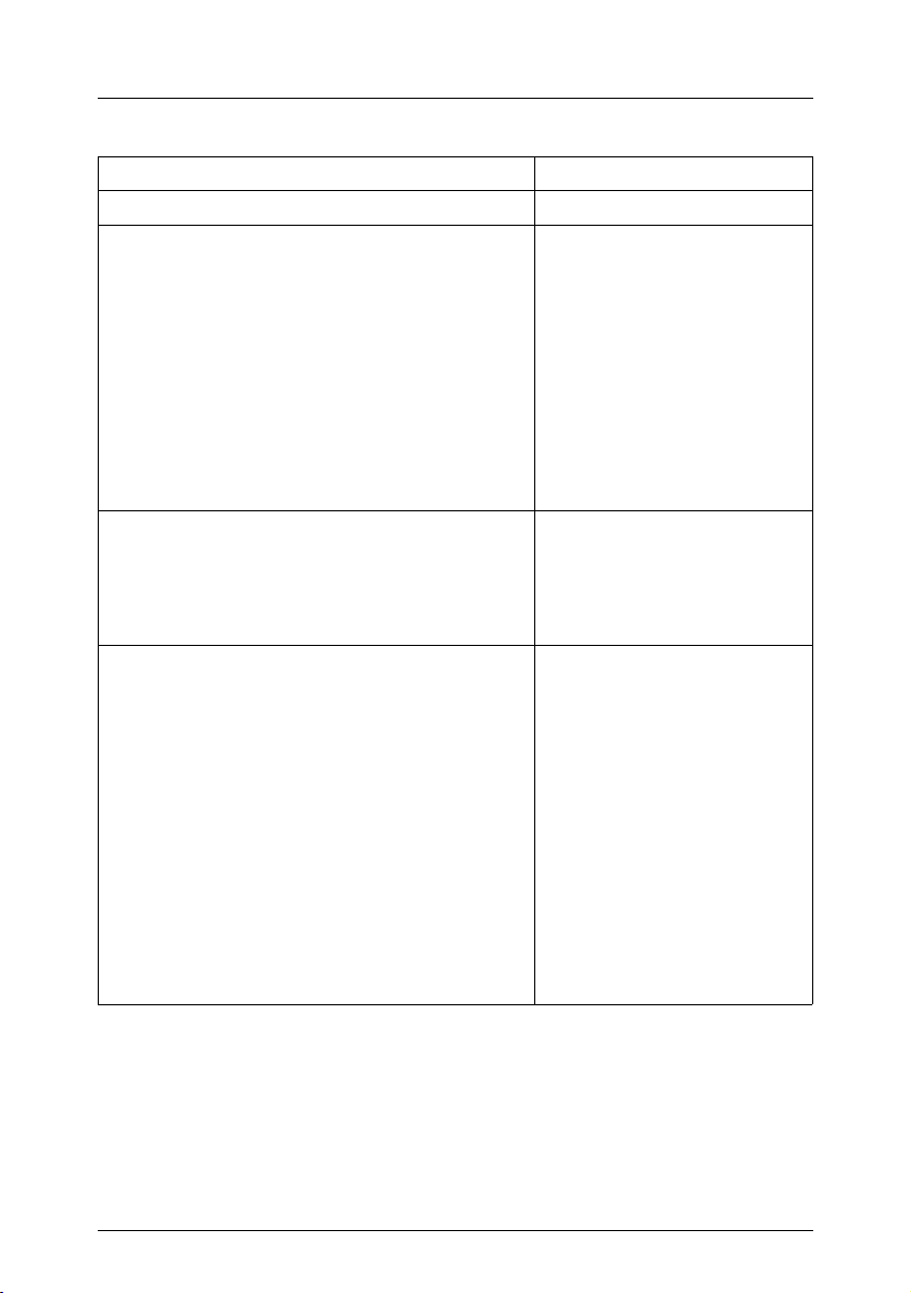
Overview of the documentation Introduction
Information/activity Manual
Detailed safety notes Safety Manual
Features and technical data of the server Operating Manual
Installation and operation, among other things:
– External connections to the server
– Operation
– Configuration of the server
– Installation of the rack mounting kit
Troubleshooting
Installation/removal of all hot-plug compo-
nents:
– Hot-plug HDD modules
Information about the system board:
– Features of the system board
– Board layout
– Jumper settings
– Replacing the battery
Extensions and upgrades:
Technical Manual
Options Guide
I For some components only the instal-
lation routine is described in the Options
Guide. Removing this components
proceed in reverse order.
– Extending/replacing main memory
– Installing a second processor/replacing the
processor
– Replacing the processor heat sink
– Installing accessible drives
– Installing controllers in non-hot-plug PCI
slots
– Installing RemoteView components
Table 1: Overview of the RX220 documentation
6 Service Supplement RX220
Page 7
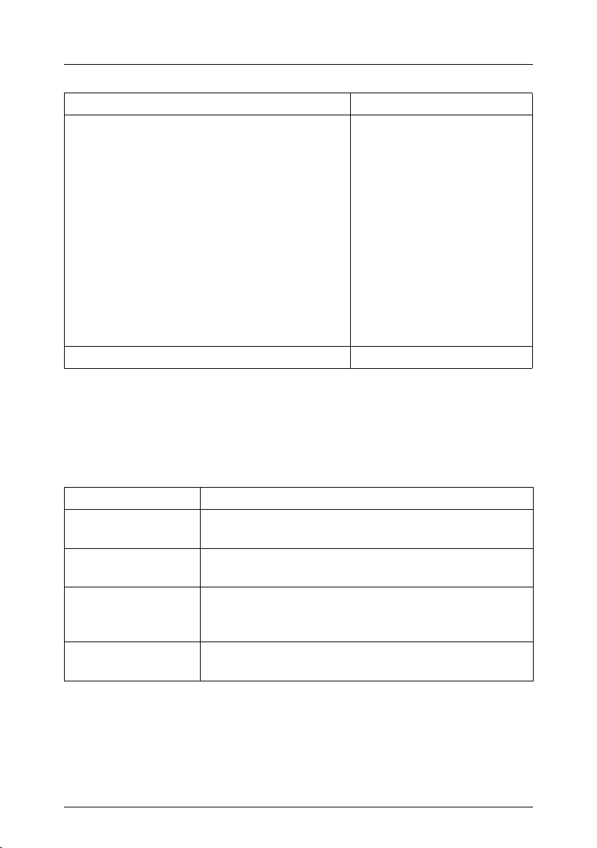
Notational conventions
Information/activity Manual
Replacement routines:
– Replacing the system fans
– Replacing the control panel board
– Replacing the power supply unit
– Replacing the internal server power supply
cable
– Replacing the chassis ID module
– Replacing the non-hot-plug hard disk
– Replacing the SATA backplane
– Replacing the fan backplane
– Replacing the system board
Board layout
Cabling
BIOS settings D2130 Setup Utility
Table 1: Overview of the RX220 documentation
Service Supplement
1.2 Notational conventions
The following notational conventions are used in this manual:
Italics indicate commands, menu items or software programs.
“Quotation marks” indicate names of chapters and terms that should be
emphasized.
Ê text which follows this symbol describes activities that
must be performed in the order shown.
V CAUTION! pay particular attention to text marked with this symbol.
Failure to observe this warning may endanger your life,
damage the server, or lead to loss of data.
I supplementary information, remarks and tips follow this
symbol.
Table 2: Notational conventions
RX220 Service Supplement 7
Page 8

Page 9

2Procedure
V CAUTION!
The actions described in this manual should only be performed by
service personnel.
Ê First of all please familiarize yourself with the safety instructions in the
chapter “Safety notes” on page 11.
Ê Make sure that all required manuals (see Service-DVD) are available,
printing out the PDF files if necessary. You will definitely need:
– the Operating Manual for the server and
– the Options Guide for the server
– the Technical Manual for the system board.
Ê Shut down the server correctly, switch it off, pull out the power plug, and
open the server as described in the chapter “Replacement routines” on
page 17.
Ê Replace the defective component, as described in the relevant chapter.
Ê Close the server.
Ê Connect up the server cables.
Ê Connect the server to the mains.
Ê Start the operating system.
Ê If necessary, perform the relevant configuration.
1
1
1
1
1
These procedures are described in the Operating Manual.
RX220 Service Supplement 9
Page 10

Page 11

3 Safety notes
I The following safety notes can also be found in the manual entitled
“Safety”.
This device complies with the relevant safety regulations for data processing
equipment.
V CAUTION!
The actions described in this manual should only be performed by
service personnel.
Before operating the device
V CAUTION!
● During installation and before operating the device, observe the
instructions on environmental conditions for your device.
● If the device is brought in from a cold environment, condensation may
form both inside and on the outside of the machine.
Wait until the device has acclimatized to room temperature and is
absolutely dry before starting it up. Material damage may be caused
to the device if this requirement is not observed.
● Transport the device only in its original packaging or in packaging
which protects it from knocks and jolts.
Installation and operation
V CAUTION!
● If the rack model is integrated in an installation that receives power
from an industrial (public) power supply network with the IEC309
connector, the (public) power supply protection must comply with the
requirements for the non-industrial (public) power supply networks for
the type A connector.
● The server automatically adjusts to a mains voltage between 100 V
and 240 V. Make sure that the local mains voltage is neither above nor
below this range.
RX220 Service Supplement 11
Page 12

V CAUTION!
● This device has a specially approved power cable and must only be
connected to a grounded insulated socket.
● Ensure that the power socket on the device or the grounded wall
outlet is freely accessible.
● The ON/OFF button does not disconnect the device from the mains
voltage. To completely disconnect it from the mains voltage, remove
the power plug from the insulated socket.
● Always connect the device and the attached peripherals to the same
power circuit. Otherwise you run the risk of losing data if, for example,
the central processing unit is still running but the peripheral device
(e.g. storage subsystem) has failed during a power outage.
● Data cables to peripheral devices must be adequately shielded.
● To the LAN wiring the requirements apply in accordance with the
standards EN 50173 and EN 50174-1/2. As minimum requirement
the use of a protected LAN line of category 5 for 10/100 MBps
Ethernet, and/or of category 5e for Gigabit Ethernet is considered.
The requirements of the specification ISO/IEC 11801 are to be
considered.
Safety notes
● Route the cables in such a way that they do not form a potential
hazard and that they cannot be damaged. When connecting up a
device, refer to the relevant notes in this manual.
● Never connect or disconnect data transmission lines during a storm
(lightning hazard).
● In emergencies (e.g. damaged casing, controls or cables, penetration
of liquids or foreign matter), switch off the device immediately and
remove the power plug.
● Proper operation of the device (in accordance with IEC 60950/
EN 60950) is only ensured if the casing is completely assembled and
the rear covers for the installation openings have been put in place
(electric shock, cooling, fire protection, interference suppression).
12 Service Supplement RX220
Page 13

Safety notes
V CAUTION!
● Only install system expansions that satisfy the requirements and
rules governing safety and electromagnetic compatibility and relating
to telecommunications terminal equipment. If you install other expansions, you may damage the system or violate the safety regulations
and regulations governing RFI suppression.
● The components or parts marked with a warning label (e.g. lightning
symbol) may only be opened, removed or exchanged by authorized,
qualified personnel.
● The warranty expires if the device is damaged during the installation
or replacement of system expansions.
● You may only set those resolutions and refresh rates specified in the
„Technical data“ section of the monitor description. Otherwise, you
may damage your monitor.
Batteries
V CAUTION!
● Incorrect replacement of batteries may lead to risk of explosion. The
batteries may only be replaced with identical batteries or with a type
recommended by the manufacturer (see the Technical Manual for the
system board).
● Do not throw batteries into the trash can. They must be disposed of
in accordance with local regulations concerning special waste.
● Replace the lithium battery on the system board in accordance with
the instructions in the Technical Manual for the system board.
● All batteries containing pollutants are marked with a symbol (a
crossed-out garbage can). The marking also contains the chemical
symbol of the heavy metal that determines the classification as a
pollutant:
Cd Cadmium
Hg Mercury
Pb Lead
RX220 Service Supplement 13
Page 14

Safety notes
Notes on handling CDs/DVDs in CD/DVD drives
V CAUTION!
● Use only CDs/DVDs in proper condition in the CD/DVD drive of your
server to prevent data loss, damage to the device, or injuries.
● Therefore, check each CD/DVD for damage, cracks, breakage etc.
before inserting it in the drive.
● Please note that any additional labels applied may change the
mechanical properties of a CD/DVD and cause imbalance.
● Damaged and imbalanced CDs/DVDs can break at high drive speeds
(data loss).
● Under certain conditions, sharp-edged pieces of broken CDs/DVDs
can penetrate the cover of the drive (cause damage to the device)
and be thrown out of the device (therefore causing injury to
uncovered body parts, particularly the face or neck).
I To protect the CD/DVD drive and prevent mechanical damage, as well as
premature wearing of the CDs/DVDs, you should observe the following
advice:
– Only insert the CDs/DVDs in the drive when needed and remove
them after use.
– Store the CDs/DVDs in suitable sleeves.
– Protect the CDs/DVDs from exposure to heat and direct sunlight.
14 Service Supplement RX220
Page 15

Safety notes
Note about the laserThe CD-/DVD-ROM drive is classified for laser class
1according to
IEC 60825-1.
V CAUTION!
The CD-/DVD-ROM drive contains a laser diode (LED). Sometimes the
LED produces a stronger laser beam than laser class 1. Direct view into
this laser beam is dangerous.
Never remove parts of the CD-/DVD-ROM drive assembly!
Modules with electrostatic-sensitive devices
Systems and components that might be damaged by electrostatic discharge
(ESD) are marked with the following label:
Figure 1: ESD label
V CAUTION!
When you handle components fitted with ESDs, you must observe the
following points under all circumstances:
● Remove the power plug from the power socket before inserting or
removing components containing ESDs.
● You must always discharge static build-up (e.g. by touching a
grounded object) before working with such components.
● The equipment and tools you use must be free of static charge.
● Use a grounding cable designed for this purpose to connect yourself
to the system unit as you install components.
RX220 Service Supplement 15
Page 16

Safety notes
V CAUTION!
● Always hold components with ESDs at the points marked green
(touch points).
● Do not touch any exposed pins or conductors on a component.
● Place all components on a static-free base.
I You will find a detailed description of handling ESD components in the
relevant European or international standards (EN 61340-5-1,
ANSI/ESD S20.20).
16 Service Supplement RX220
Page 17

4 Replacement routines
V CAUTION!
When handling systems and boards, make sure you observe the safety
information in the chapter “Safety notes” on page 11.
4.1 Preparation
To replace non-hot-plug components, proceed as follows:
Ê Shut down the operating system.
Ê Switch the server off.
Ê Pull the power plug out of the safety socket.
4.1.1 Opening/closing the server
1
1
2
Figure 2: Removing the server
Ê Undo the knurled screws (1) and pull the server carefully out of the rack as
far as it will go (2).
In most cases it makes sense to remove the server from the rack cabinet.
RX220 Service Supplement 17
Page 18

Preparation Replacement routines
V CAUTION!
The server has no cable management in the rack!
Therefore you must unplug all cables connected to the server before
you remove it.
I How to remove the server from the rack cabinet is described in the
Operating Manual.
Figure 3: Taking off the housing cover
Ê Undo the knurled screw at the back of the device.
Ê Push the server cover backward (2) a few centimeters using the recessed
grips (3).
Ê Lift up the housing cover and remove it.
To close the cover, follow the instructions above in reverse order.
18 Service Supplement RX220
Page 19

Replacement routines Replacing the fans
4.2 Replacing the fans
The server contains seven replaceable fan modules.
memory fan
system fans
system fans
system fans
system fans
memory fan
power supply fans
Figure 4: system fan (overview)
– 4 system fan modules, consisting of 2 fans each.
– 2 memory fan modules
– 1 power supply fan module, consisting of 2 fans
If one fan fails, replace this fan to guarantee the required air flow in the system.
RX220 Service Supplement 19
Page 20

Replacing the fans Replacement routines
System fans
Figure 5: System fans
V CAUTION!
A defective fan module must not be replaced during operation.
Rotating parts involve an increased risk of injury. Make sure that the fan
blades have stopped turning before removing the fan module.
Ê Open the server as described in the section “Preparation” on page 17.
20 Service Supplement RX220
Page 21

Replacement routines Replacing the fans
1
Figure 6: Removing a system fan module
Ê Pull the plug of the defective system fan module out of the fan board (1).
Ê Lift the defective system fan module out of the system.
Ê Insert the new system fan module.
Ê Connect the plug of the new system fan module with the fan backplane.
RX220 Service Supplement 21
Page 22

Replacing the fans Replacement routines
Figure 7: Arrow indicating the direction of the outward airflow.
V CAUTION!
Make sure you install the fan in the correct direction. The direction of the
outward airflow is indicated on the top of the fan housing and must be the
same as that of the other fans.
Ê Close the server and connect all power plugs (for a detailed description see
the Options Guide).
22 Service Supplement RX220
Page 23

Replacement routines Replacing the fans
Memory fans
Figure 8: Removing / installing memory fans
Ê Remove the fan module as described on page 21(removing of a system fan).
Ê Install the fan module as described on page 21(installing of a system fan).
RX220 Service Supplement 23
Page 24

Replacing the fans Replacement routines
Power supply fans
Figure 9: Installing/removing power supply fans
Ê Remove the fan module as described on page 21(removing of a system fan)
Ê Install the fan module as described on page 21(installing of a system fan).
24 Service Supplement RX220
Page 25

Replacement routines Replacing the control panel board
4.3 Replacing the control panel board
In case of defective control panel LEDs, buttons or connectors replace the
complete control panel board.
I In the PRIMERGY RX220 server, the ambient temperature is measured
on the control panel board. If the ambient temperature sensor is
defective, replace the complete control panel board.
Ê Open the server as described in the section “Preparation” on page 17.
Figure 10: Opening the maintenance cover of the control panel
Ê Undo the screw (see figure) and lift the maintenance cover carefully to
remove the control panel.
V CAUTION!
The control panel is screwed with the maintenance cover.
RX220 Service Supplement 25
Page 26

Replacing the control panel board Replacement routines
Figure 11: Removing the control panel board
Ê Unplug the cable on the control panel board.
Ê Undo both screws (see figure).
Ê Remove the control panel board.
Ê Insert the new control panel board.
Ê Fasten the control panel board with the 2 screws.
Ê Plug the cable on the control panel board.
Ê Insert the maintenance cover and fasten it with the screw.
Ê Close the server and connect all power plugs (for a detailed description see
the Options Guide).
26 Service Supplement RX220
Page 27

Replacement routines Replacing the power supply unit
4.4 Replacing the power supply unit
Ê Open the server as described in the section “Preparation” on page 17.
Figure 12: Removing the power supply unit dummy cover
Ê Undo both screws (see figure) and remove the power supply unit dummy
cover.
RX220 Service Supplement 27
Page 28

Replacing the power supply unit Replacement routines
Figure 13: Pulling out the internal power supply cable’s connector
Ê Pull the internal power supply cable’s connector out of the power supply unit
and bend it carefully to the side (see figure).
1
4
3
2
6
5
Figure 14: Position of the connectors of the power supply
Ê Pull out the connectors of all the cables attached to the power supply unit
(see 1-6 in the figure above).
28 Service Supplement RX220
Page 29

Replacement routines Replacing the power supply unit
Figure 15: Opening the cable clamp
Ê Open the cable clamp.
Figure 16: Removing the power supply unit from the housing
Ê Pull the power supply unit carefully out of the housing.
I When doing this ensure that the internal power supply cable (see
circle) is not pinched.
RX220 Service Supplement 29
Page 30

Replacing the power supply unit Replacement routines
Figure 17: Cable ducts inside the housing
V CAUTION!
Push the cables and connectors carefully through the cable ducts inside
the housing (see figure) to avoid damaging them.
To install the power supply unit follow the above steps in reverse order.
Ê Close the server and connect all power plugs (for a detailed description see
the Options Guide).
30 Service Supplement RX220
Page 31

Replacement routines Replacing the internal server power supply cable
4.5 Replacing the internal server power supply
cable
Ê Open the server as described in the section “Preparation” on page 17.
Ê Remove the power supply unit as described in the section “Replacing the
power supply unit” on page 27.
Figure 18: Position of the cable clamps of the internal power supply cable
Ê Open the cable clamps and remove the internal power supply cable.
RX220 Service Supplement 31
Page 32

Replacing the internal server power supply cable Replacement routines
1
2
Figure 19: Removing the line filter
Ê Press down the two edges of the line filter’s stop spring (both at the top (1)
and at the bottom (2)).
I To permit access to the stop spring on the underside of the line filter
access holes are provided both at the side and on the underside of
the server housing.
Ê Now push the line filter out at the rear through the opening in the housing.
Ê Push the line filter in at the rear through the opening in the housing.
Ê Insert the internal power cable into the cable clamp and close the cable
clamp.
Ê Close the server and connect all power plugs (for a detailed description see
the Options Guide).
32 Service Supplement RX220
Page 33

Replacement routines Replacing the chassis ID module
4.6 Replacing the chassis ID module
Ê Open the server as described in the section “Preparation” on page 17.
Figure 20: Removing the chassis ID module
Ê Remove the I2C bus cable from the chassis ID module (see figure).
Ê Undo the screw and remove the chassis ID module.
Ê Insert the chassis ID module and fasten it with the screw.
Ê Plug the I
Ê Close the server and connect all power plugs (for a detailed description see
the Options Guide).
2
C bus cable.
I To enable ServerView and ServerStart to identify the system, the Chassis
ID-Prom must be reprogrammed using the “Chassis ID Prom tool” after
the new chassis ID module has been installed.
You will find this tool on the ServerSupport CD or you can download it
from the service and support area of Fujitsu Siemens Computers (FSC
Web Server/URL:
http://extranet.fujitsu-siemens.com/service/information/intelservers/tools).
RX220 Service Supplement 33
Page 34

Replacing the non-hot-plug hard disk Replacement routines
4.7 Replacing the non-hot-plug hard disk
The non-hot-plug hard disk is accommodated in a sturdy mounting assembly
and must be dismounted in order to replace it.
Figure 21: Mounting assembly with a non-hot-plug hard disk
Ê Open the server as described in the section “Preparation” on page 17.
34 Service Supplement RX220
Page 35

Replacement routines Replacing the non-hot-plug hard dis
k
2
1
Figure 22: Dismounting the non-hot-plug hard disk
Ê Remove the two cables (1) from the SATA hard disk.
I The SATA cable’s connector has a retaining catch which must be
pressed to pull it out. This is on the underside here and therefore
cannot be seen.
Ê Loosen the hard disk housing’s knurled screw (2).
Ê Pull the hard disk mounting assembly out.
Ê Remove the hard disk from the mounting assembly by undoing the four
screws (see figure 21 on page 34).
Ê Install the non-hot-plug hard disk following the above steps in reverse order.
Ê Close the server and connect all power plugs (for a detailed description see
the Options Guide).
RX220 Service Supplement 35
Page 36

Replacing the SATA backplane Replacement routines
4.8 Replacing the SATA backplane
Ê Open the server as described in the section “Preparation” on page 17.
Ê Disconnect the data cable of the CD/DVD drive. Carefully fold the cable to
the side.
Ê Remove all the other cables from the SATA backplane.
Ê Pull both hard disk modules out slightly.
Figure 23: Removing the SATA backplane
Ê Loosen the knurled screw (see figure) from the SATA backplane, then move
the backplane to the direction of the arrow until its holes disengage from the
housing stand-offs.
Lift the SATA backplane, then set it aside.
Ê Install the new SATA backplane, match its holes with the housing stand-offs
then move it to the opposite direction to lock.
I Be careful of the hard disk connections and the lighting wires.
Ê Fasten the knurled screw.
Ê Connect all cables to the SATA backplane (see page 42).
Ê Push both hard disk modules inward.
36 Service Supplement RX220
Page 37

Replacement routines Replacing the fan backplane
Ê Connect the cables of the accessible drives.
Ê Close the server and connect all power plugs (for a detailed description see
the Options Guide).
4.9 Replacing the fan backplane
Ê Open the server as described in the section “Preparation” on page 17.
Ê Remove all the cables from the fan backplane.
Figure 24: Removing the fan backplane
Ê Loosen the knurled screw (see figure) from the fan backplane, then move the
backplane to the direction of the arrow until its holes disengage from the
housing stand-offs.
Lift the fan backplane, then set it aside.
Ê Install the new fan backplane, match its holes with the housing stand-offs
then move it to the opposite direction to lock.
Ê Connect all cables to the fan backplane (see page 45).
Ê Close the server and connect all power plugs (for a detailed description see
the Options Guide).
RX220 Service Supplement 37
Page 38

Replacing the system board Replacement routines
4.10 Replacing the system board
Ê Open the server as described in the section “Preparation” on page 17.
Ê Disconnect all external cables on the rear side of the server
Removing the system board
Ê Remove the memory modules (the relevant procedure is described in the
Options Guide).
Ê Remove the air duct, the heat sink(s) and processor(s)
(the relevant procedure is described in the Options Guide).
Ê Remove the riser card holders (the relevant procedure is described in the
Options Guide).
Ê Remove all cables connected to the system board.
Figure 25: Positions of the screws on the system board
Ê Remove 11 system board screws (see figure on page 38).
Ê Push the system board about 1 am in the direction of the housing front.
38 Service Supplement RX220
Page 39

Replacement routines Replacing the system board
Ê Hold the system board on both sides and lift it carefully out of the housing.
Installing the system board
Ê Insert the system board at a slight angle and slide the connectors through
the recesses on the rear side.
Ê Carefully lower the system board into the housing.
If necessary, adjust the position of the system board by turning it slightly until
the screw holes align with the threads on the floor plate.
Ê Fasten the system board with 11 screws.
Ê Reconnect all cables.
I For cabling information see section “Cabling” on page 44.
Ê Reinstall the riser card holders (the relevant procedure is described in the
Options Guide).
Ê Reinstall the air duct, the heat sink(s) and processor(s)
(the relevant procedure is described in the Options Guide).
Ê Reinstall the memory modules (the relevant procedure is described in the
Options Guide).
Ê Close the server and connect all power plugs (for a detailed description see
the Options Guide).
I After installing the new system board, it is important that you perform the
following steps to ensure faultless operation:
– update the BIOS firmware.
– set the BIOS defaults
– define the customer-specific settings
– recalibrate the fans
RX220 Service Supplement 39
Page 40

Page 41

5 Appendix
5.1 Board layout
I The board layout of the system board is described in the Technical
Manual of the system board D2130.
5.1.1 Control panel board
Part number: SNP:A3C40066829
1
2
Figure 26: Control panel board
# Connection
1 USB34 connector on system board
2 PANEL1 connector on system board
RX220 Service Supplement 41
Page 42

Board layout Appendix
5.1.2 SATA backplane
Part number: SNP:A3C40065010
1
Figure 27: Connector assignment on the SATA backplane
# Connection
1 Power supply
2 SATA LED controller connector (I2C_SATA1) on system board
3 SATA1 connector on system board
4 SATA2 connector on system board
5 SATA HDD1 data and power connector
6 SATA HDD2 data and power connector
7 IDTEMP Combo board (SNP:A3C40038146)
23 4 5
67
42 Service Supplement RX220
Page 43

Appendix Board layout
5.1.3 Fan backplane
Part number: SNP:A3C40061146
10
3
4
5
6
1
2
9
Figure 28: Connections on the fan backplane
# Connection
1 Double system fan module for power supply unit
2 Single system fan module for memory modules
3 Double system fan module for CPU2
4 Double system fan module for CPU2
5 Double system fan module for CPU1
6 Double system fan module for CPU1
7 Single system fan module for memory modules
8 PANEL2 connector on system board
9 PSU signal connector from power supply unit
10 Power plug from power supply
11 IDTemp Combo board (SNP:A3C40038146)
7
8
11
RX220 Service Supplement 43
Page 44

Cabling Appendix
5.2 Cabling
5.2.1 Cable overview
# Part number/
ASUS No
1 SNP:A3C40068551/
14G000900700
2 SNP:A3C40068552/
14G030001900
3 SNP:A3C40068547/
14G000900520
4 SNP:A3C40068548/
14G032804210
5 SNP:A3C40068550/
14G000900800
6 Mit Lüfter verbunden Fan control cable Fan board Fan
7 Mit Lüfter verbunden Fan control cable Fan board Fan
8 SNP:A3C40068545/
14G00380170
9 SNP:A3C40072583/
14G003801702
10 SNP:A3C40068546/
14G030001800
11 SNP:A3C40068553/
14G000101200
12 T26139-Y3874-V2 IPMB cable RSB S2 LP System board
13 SNP:A3C40057519 RSB S2 power cable System board
Description From To
Operating panel cable System board
D2130
USB cable System board
D2130
IDE cable for
CD/DVD/CD-RW drive
I²C bus cable for
IDTEMP combo
Fan control cable System board
SATA cable System board
SATA cable System board
I²C bus cable for SATA
backplane
Y power supply cable PSU plug P4 Non-hot-plug
System board
D2130
SATA / Fan
backplane
D2130
D2130
D2130
System board
D2130
D2130
D2130
Operating
panel board
Operating
panel board
CD/DVD drive
IDTEMP
combo
Fan
backplane
backplane
backplane
SATA back-
plane resp.
SATA-HDD
SATA backplane resp.
SATA-HDD
SATA backplane
SATA-HDD
RSB S2 LP
RSB S2 LP
44 Service Supplement RX220
Page 45

Appendix Cabling
5.2.2 Cable layout
Variant hot-plug SATA hard disk
!
R S B S 2 L P
%
P o w e r
s u p p l y
u n i t
S A T A 1
&
S A T A 2
'
!
B M C
P 2
P 1
$
$
P 3
P 4
$
F a n b a c k p l a n e
S A T A b a c k p l a n e
S A T A 2
S A T A 1
H a r d d i s k 1
$
$
H a r d d i s k 2
P 5
$
"
#
I D T E M P C o m b o
C D - R O M /
D V D / C D - R W
O p e r a t i n g
p a n e l
Figure 29: Cable connections of the RX220 hot-plug
RX220 Service Supplement 45
Page 46

Cabling Appendix
Variant non-hot-plug
!
R S B S 2 L P
%
P o w e r
s u p p l y
u n i t
&
'
!
S A T A 1
S A T A 2
P 2
P 1
P 4
C D - R O M /
D V D / C D - R W
P 3
$$
H a r d d i s k 1
P 5
$
F a n b a c k p l a n e
$
B M C
$
H a r d d i s k 2
$
"
I D T E M P C o m b o
#
O p e r a t i n g
p a n e l
Figure 30: Cable connections of the RX220 non-hot-plug
46 Service Supplement RX220
Page 47

Index
A
ambient temperature sensor
mounting location 25
B
batteries 13
C
cable overview 44
cabling layout 45
chassis ID module
replace 33
reprogram 33
control panel board
connections 41
parts number 41
E
electrostatic sensitive devices 15
ESD 15
ESD label 15
F
fan backplane
connections 42
parts number 42
replace 37
H
housing cover
remove 18
L
light-emitting diode (LED) 15
line filter
removal 32
lithium battery
exchange 13
M
meaning of the symbols 7
N
non-hot-plug hard disk
replace 34
notational conventions 7
note about the laser 15
notes
on handling CDs 14
P
power supply unit
dummy cover 27
internal server power supply
cable 31
Position of connectors 28
replace 27
R
remove
housing cover 18
replace
chassis ID module 33
fan backplane 37
line filter 32
non-hot-plug hard disk 34
SATA backplane 36
system board 38
system fans 19
replace power supply unit 27
reprogramming the chassis ID
module 33
S
SATA backplane
replace 36
SATA cable connectors 35
Service-CD 5
stop spring of the line filter 32
system board
replace 38
screw positions 38
RX220 Service Supplement 47
Page 48

Index
system fans
replace 19
T
target group 5
48 Service Supplement RX220
Page 49

Fujitsu Siemens Computers GmbH
User Documentation
81730 Munich
Germany
Fax: (++49) 700 / 372 00000
email: manuals@fujitsu-siemens.com
http://manuals.fujitsu-siemens.com
Submitted by
Comments
Suggestions
Corrections
Comments on PRIMERGY RX220
Server System
✁
RX220
Page 50

Page 51

Fujitsu Siemens Computers GmbH
User Documentation
81730 Munich
Germany
Fax: (++49) 700 / 372 00000
email: manuals@fujitsu-siemens.com
http://manuals.fujitsu-siemens.com
Submitted by
Comments
Suggestions
Corrections
Comments on PRIMERGY RX220
Server System
✁
RX220
Page 52

Page 53

Information on this document
On April 1, 2009, Fujitsu became the sole owner of Fujitsu Siemens Computers. This new subsidiary of Fujitsu has been renamed Fujitsu Technology Solutions.
This document from the document archive refers to a product version which
was released a considerable time ago or which is no longer marketed.
Please note that all company references and copyrights in this document have
been legally transferred to Fujitsu Technology Solutions.
Contact and support addresses will now be offered by Fujitsu Technology Solutions and have the format …@ts.fujitsu.com.
The Internet pages of Fujitsu Technology Solutions are available at
http://ts.fujitsu.com/...
and the user documentation at http://manuals.ts.fujitsu.com.
Copyright Fujitsu Technology Solutions, 2009
Hinweise zum vorliegenden Dokument
Zum 1. April 2009 ist Fujitsu Siemens Computers in den alleinigen Besitz von
Fujitsu übergegangen. Diese neue Tochtergesellschaft von Fujitsu trägt seitdem den Namen Fujitsu Technology Solutions.
Das vorliegende Dokument aus dem Dokumentenarchiv bezieht sich auf eine
bereits vor längerer Zeit freigegebene oder nicht mehr im Vertrieb befindliche
Produktversion.
Bitte beachten Sie, dass alle Firmenbezüge und Copyrights im vorliegenden
Dokument rechtlich auf Fujitsu Technology Solutions übergegangen sind.
Kontakt- und Supportadressen werden nun von Fujitsu Technology Solutions
angeboten und haben die Form …@ts.fujitsu.com.
Die Internetseiten von Fujitsu Technology Solutions finden Sie unter
http://de.ts.fujitsu.com/..., und unter http://manuals.ts.fujitsu.com finden Sie die
Benutzerdokumentation.
Copyright Fujitsu Technology Solutions, 2009
 Loading...