

Fujitsu Siemens Computers Primergy Econel 100 Series, Primergy Econel 130 Series Operating Manual
Page 1

Server English
Operating Manual
PRIMERGY
Econel 100 / 130 Series
Page 2

Are there ...
... any technical problems or other questions that you would like help with?
Please contact:
• our Hotline/Help Desk (refer to the enclosed Help Desk List or go to:
"
http://www.fujitsu-siemens.com/support/")
• your sales partner
• your sales office
Further information can be found in the "Safety" and "Warranty" manuals.
Latest information about our products, useful tips, updat es etc. are available
on our website: "
www.fujitsu-siemens.com"
Page 3

Page 4

This manual was produced by Xerox Global Services
Published by
Fujitsu Siemens Computers GmbH
AG 02/08
Edition 3
Order no.: A26361-K1182-Z120-1-7619
Page 5

PRIMERGY Econel 100 / 130 Series
Your PRIMERGY Econel Server... 1
Important notes 4
Getting started
8
Operation
19
Property and data protection
25
Troubleshoo
ting and tips
30
System expansions
35
Technical data
61
Index
62
Operating Manual
Page 6

All trademarks used are trademarks or registered trademarks of their respective
owners, whose protected rights are acknowledged.
Copyright © Fujitsu Siemens Computers G mbH 2008
All rights reserved, including rights of translation, reproduction by printing, copying
or similar methods, in part or in whole.
In the event of violations, perpetrators will be liable to prosecution for damages.
All rights reserved, including rights created by patent grant or registration of a utility model or design.
Subject to availability and technical m odi fications.
Page 7

Contents
Contents
YourPRIMERGY EconelServer... ....................................................... 1
Target group of this operating manual . . ................................................... 1
Notational conventions .................................................................. 2
Informationsources ..................................................................... 3
Importantnotes ........................................................................ 4
Safetyinformation ....................................................................... 4
Transporting the devic
e ..................................................................
4
Cleaning the device ..................................................................... 5
Energy saving, dispos
aland recycling ....................................................
5
CEmarking ............................................................................ 5
FCC Class A Compliance
Statement(Econel 100only) ....................................
6
FCC Class B Complianc
eStatement (Econel130 only) ....................................
7
Gettingstarted ......................................................................... 8
Unpacking and ch ecking the delivery . . ................................................... 8
Stepsfor initial setup .................................................................... 8
Choosing a location and setting up the device . . . . . ........................................ 9
Connecting external devices . . ........................................................... 10
Connecting the cables . .............................................................. 10
Disconnecting the cables . . . . . ....................................................... 10
Portson the device .................................................................. 11
Connecting the monitor . . . ........................................................... 12
Connecting the mouse . . . . ........................................................... 13
Connecting the keyboard . ........................................................... 13
Connecting external devices to the parallel or serial port . . . ............................. 13
Connecting external devices to the USB ports . ........................................ 14
Connecting the device to the mains voltage (device-dependent) ............................. 15
Switchingon monitorand device ......................................................... 16
Switchingon thedevice (with main powerswitch) ..................................... 17
Switchingon thedevice (withoutmain powerswitch) .................................. 18
Installingthe software ................................................................... 18
Operatio
n ..............................................................................
19
Switch th
edevice on ....................................................................
19
Switchin
goffthe device .................................................................
19
Other wa
ys of switching on and off ....................................................
20
Indicat
orson the device .................................................................
20
Keyboar
d ...............................................................................
21
Import
ant keys and keyboard shortcuts . . . . ............................................
22
Configu
re device ........................................................................
23
Config
uringwith ServerStartor EasySetup ............................................
23
Config
uration without ServerStart . . ...................................................
23
Config
uringthe SATA RAIDcontroller .................................................
24
Sett
ingsin BIOSSetup ..................................................................
24
Propertyand dataprotection ........................................................... 25
Mechanical access protection ............................................................ 25
Detection of unauthorised opening . ................................................... 25
Mechanical casing lock (optional) . . ................................................... 26
Anti-theft protection and lead-sealing . . . . . . ............................................ 27
BIOSsetup security functions ............................................................ 28
A26361-K1182-Z120-1-7619, edition 3
Page 8

Contents
Access authorisation via external SmartCard r eader . . . . . .................................. 28
Accessprotection withSystemLock ....................................................... 29
Operating the SmartCard reader . . . . . ................................................. 29
Troubleshooting andtips .............................................................. 30
Troubleshooting . . ....................................................................... 30
Powerindicator remainsoff afteryou have switched onyour device ..................... 30
The device cannot be switched off with the ON/OFF switch. . . .......................... 31
Monitorremains blank ............................................................... 31
Nomouse pointerdisplayed onthe screen ............................................ 32
The floppy disk cannot be read or written . ............................................. 32
Drivesat systemstart "dead" ......................................................... 33
Addeddrive faulty ................................................................... 33
Time and/or date is not correct . . . . . . ................................................. 33
Errormessages onthe screen ........................................................ 33
Installingnew software .................................................................. 34
Systemexpansions .................................................................... 35
Information about board s ................................................................ 36
Opening the casing . . ................................................................... 37
Coverremoval ...................................................................... 37
Opening the drive cage . . ............................................................ 38
Closingthe casing ...................................................................... 39
Closingthe drivecage ............................................................... 39
Attachingthe cover .................................................................. 40
Installingthe locking device withcasing lock .............................................. 41
Removingthe locking device ........................................................ 41
Installingthe lockingdevice with casing lock ........................................... 42
Removingventilation duct ............................................................... 43
Ventilationduct installing ................................................................ 44
Installing and removing heat sinks ........................................................ 45
Removingheat sinks ................................................................ 45
Installingheat sinks ................................................................. 46
Installing and removing additional fans (devices with four hard disks) . . . . . ................... 46
Removingadditionalfans ............................................................ 47
Installingadditional fans ............................................................. 47
Installing and removing a board . . ........................................................ 48
Remove the slotcover. .............................................................. 48
Installing a board . . . . ................................................................ 49
Removingboards ................................................................... 49
Reinstallinga slotcover .............................................................. 50
Low-profileboards ...................................................................... 51
Fitting a slot adapter . ................................................................ 51
Removing a slot adapter . ............................................................ 52
Installingand removingdrives ............................................................ 52
Installingand removingaccessible drives .............................................. 53
Installing and removing an accessible 3
1
/2inchdrive (e.g. diskette drive) ................. 55
Installingand removingthe harddisk drive ............................................ 56
Mainboard expansions . . ................................................................ 59
Upgradingmain memory ............................................................. 59
Replacingthe processor ............................................................. 60
Technicaldata ......................................................................... 61
A26361-K1182-Z120-1-7619, edition 3
Page 9

Contents
Index .................................................................................. 62
A26361-K1182-Z120-1-7619, edition 3
Page 10

Contents
A26361-K1182-Z120-1-7619, edition 3
Page 11

Your PRIMERGY Econel Server...
Your PRIMERGY Econel Server..
.
Overview
... is a server for workgroups and small networks. The server is suitable for file server services and
as an application, information or Internet server. The PRIMERG Y Econel Server offers a high level
of data security an d availability thanks to sophisticated hardware and software components.
It is available in a variety of configurations which differ in terms of the hardware and software
used. You can install accessible drives (for example a DVD drive) and other m odules.
You can con figure and manage your PRIMERGY server quickly an d efficiently
using the supplied ServerStart or EasySetup software. User-friendly menus are
provided for installing the server operating systems.
The device is service-friendly and of modular design, so that maintenance can
be carried out quickly and easily. The flash EPROM p rogram supplied with the
Fujitsu Siemens Computers utilities supports fast BIOS update.
Security functions in the BIOS Setup and on the mainboard protect the data on the server against
manipulation. Due to the supported RAID level, the hard drive controllers offer error tolerance
through data redundancy for users requiring complete protection for their valuable data.
This manual tells you how to start using your device and how to operate it in daily use.
This manual applies for all configuration levels. Depending on the cho sen configuration
level, some of the hardware components described may not be available on your PC.
Please also read the notes about your operating system.
Target group of this operating manual
Targetgroup
The operating manual is i
ntended for persons who are responsible for installing and operating the
device. The operating ma
nual describes how to start up and operate the PRIMERGY Econel Server.
To understand the manual
requires knowledge of hardware and data transmission, as well as a
basic knowledge of the op
erating system used. A knowledge of English is also required.
A26361-K1182-Z120-1-7619, edition 3 1
Page 12
Your PRIMERGY Econel Server...
Notational conventions
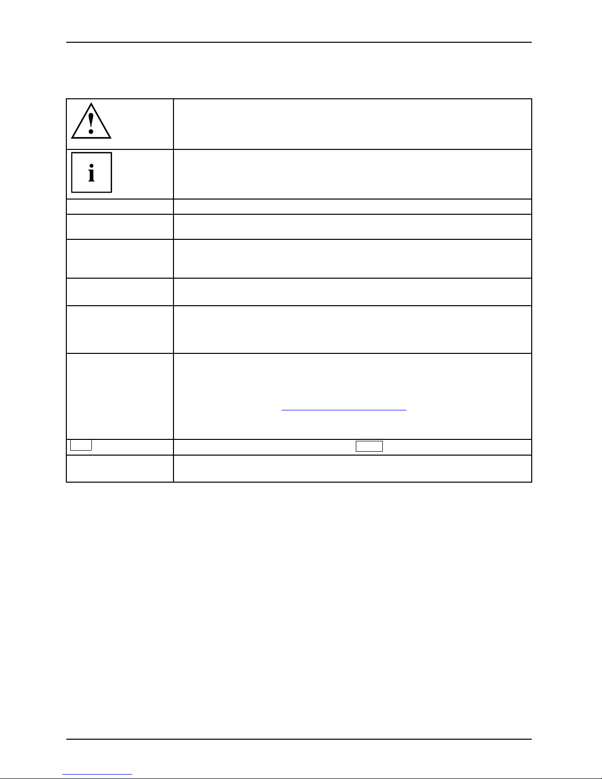
Pay particular attention to text marked with t his symbol. Failure to observe
this warning will endanger your life, will damage the device or lead to loss
of data. The warranty will be invalidated if you c ause defects in the device
through failure to take notice of this warning
indicates important informat
ion that is required to use the device properly.
►
indicates an activity that must be performed in the order shown
indicates a result
This style
flags data entered using the keyboard in a program dialog or command
line, e.g . your password (Name123) or a command to launch a program
(start.exe)
This style
refers to information displayed by a program on the screen, e.g.:
Installation is completed
This style
is for
• terms and texts i n a softwar
e user interface, e.g.: Click Save.
• names of programs or files, e.g. Windows or setup.exe.
"This style"
is for
• cross-references to another section, e.g. "Safety information"
• cross-references to an external source, e.g . a web address: For more
information, go to "
www.fujitsu-siemens.com"
• indicates name s of CDs and DVDs as well as names and titles of other
materials, e.g.: "CD/DVD Drivers & Utilities" or "Safety" manual
Abc
refers to a key on the keyboard, e.g.:
F10
This style
flags concepts and text that are emphasised or highlighted, e.g.: Do not
switch off device
2 A26361-K1182-Z120-1-7619, edition 3
Page 13
Your PRIMERGY Econel Server...
Information sources
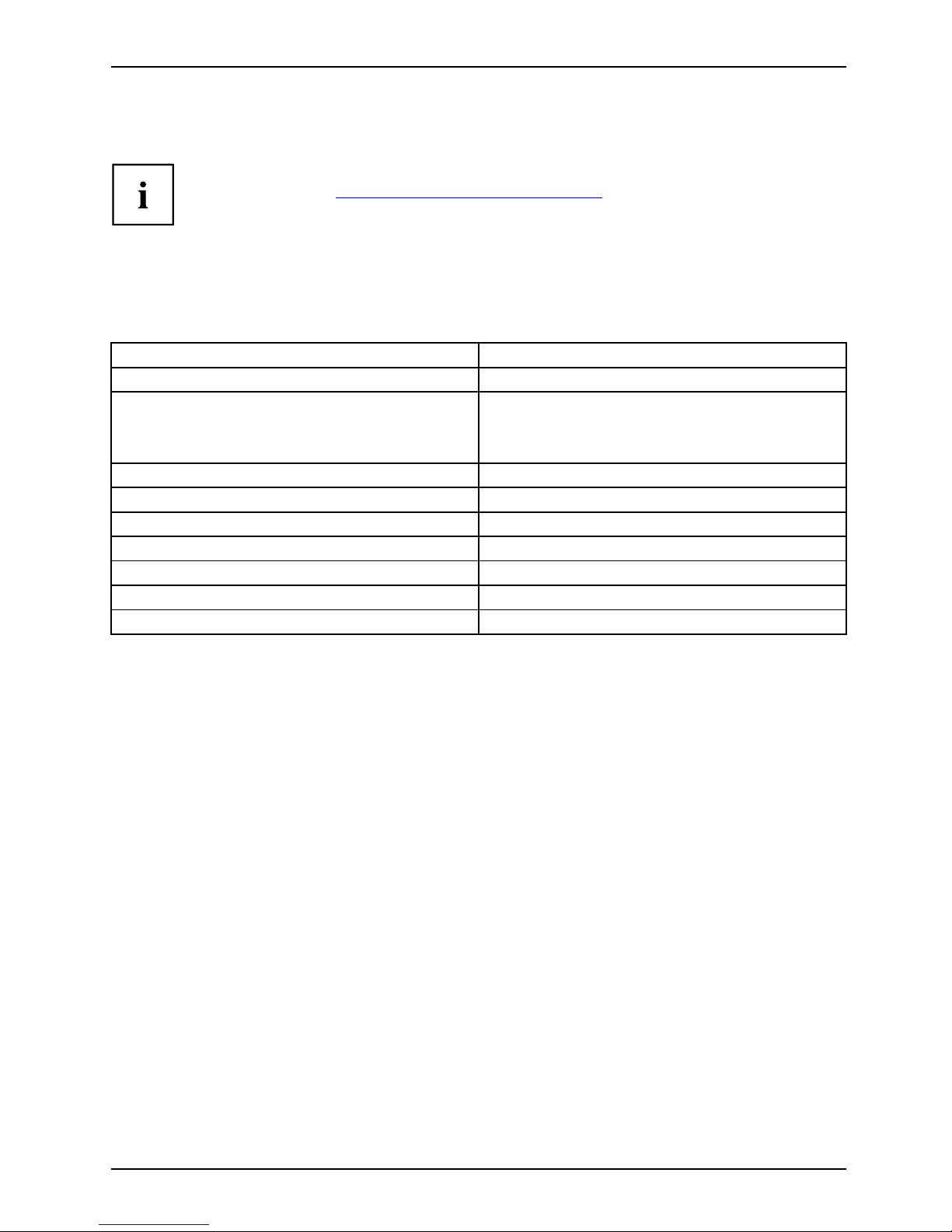
OverviewInformation
The information sources are also available to download free of charge from
our website. Visit "
http://manuals.fujitsu-siemens.com" for an overview of the
on-line documentation available via the Internet.
For documentation on the PRIMERGY Econel Server, go to Industry standard servers.
Information sources for the PRI
MERGY Econel Server:
The following manuals in PDF for
mat can be found on the "Drivers & Utilities" DVD
supplied with every device as p a
rt of the ServerView Suite software.
Type of information Where?
"Getting Started Hardware" poster
Printed
Information on ServerView Suite
software
•"ServerStart"DVD
• "ServerBooks" DVD
• "ServerSupport" DVDs
"BIOS Setup" man ual PDF file
RAID software m a nual PDF file
"Safety" manual
Printed
"Warranty" manual
PDF file
"Ergonomics" manual
PDF file
"Returning used devices" m an ual
PDF file
"Helpdesk" supplement Printed
Further information sources:
• Monitor operating manual
• Mainboard manual
• Documentation for your operating system
• Information files for your operating system (e.g. *.PDF, *.HTML, *.DOC, *.CHM, *.TXT, *.HLP)
A26361-K1182-Z120-1-7619, edition 3 3
Page 14
Important notes
Important notes
ImportantnotesNotes
In this chapter you will find information regarding safety which it is essential to
take note of when working with your device.
Safety information
SafetyinformationNote
Please note the information prov
ided in the "Safety" manual and
in the following safety notes.
When installing and operating th
e device, please observe the notes on
environmental conditions in "
Te
chnical data", Page 61 as well as the
instructions in "
Getting start
ed", Page 8.
You must only op erate the device i
f the rated voltage for the device
matches the local mains supply
voltage. Check the rated voltage set for
this device (see "
Getting sta
rted", Page 8).
ThemainswitchandtheON/OFFs
witch do not disconnect the device
from the mains voltage. To com
pletely disconnect the mains voltage,
remove the power plug from the
power socket.
Replace the lithium battery o
n the mainboard in accordance with the
instructions in the manual fo
r the mainboard.
Use only notebooks with prot
ection class 2.
The activities described in
these instructions must only be performed by qualified
engineers. Repairs to the de
vice must only be performed by qualified technicians.
Unauthorised opening and in
correct repairs could put the user at great risk or cause
serious damage to the equip
ment (electric shock, hazardous energy emissions, risk of
fire). Opening the unit with
out authorisation voids the warranty and cancels any liability.
Transporting the d evice
Device,Transpor tationRetransportation
Transport all parts sep arately in their original packaging or in a packaging which
protects them from knocks and jolts, to the new site.
Do not unpack them until all transportation manoeuvres are completed.
Ask somebody else to help you lift and carry the device.
4 A26361-K1182-Z120-1-7619, edition 3
Page 15
Important notes
Cleaning the device
Device,Transpor tationRetransportationSystem unit,seeDevice
Turn off all power and equipment switches and remove the power
plug from the mains supply.
Do not clean any interior parts yourself, leave this job to a service technician.
Do not use any cleaning agents that con tain abrasives or may corrode plastic.
Never clean the device with water! Water entering into the device could
present a serious risk to users (e.g. electric shock).
Ensure that no liquid enters the system.
Thesurfacecanbecleanedwithadry
cloth. If particularly dirty, use a cloth that has been
moistened in mild domestic deterge
nt and then carefully wrung out.
Use disinfectant wipes to clean the
keyboard and the mouse.
Air filters should be cleaned or rep
laced on a reg ular basis. Clogged or soiled air filters
will result in increased interio
r temperatures in the device. Excessively high operating
temperatures may result in loss o
f data and/or unreliable operation.
Energy saving, disposal and recycling
DisposalEnergysavingRecyclingDrivers&UtilitiesDVDUserDocumentationDVD
Further information can be found on the "Drivers & Utilities" DVD.
CE marking
CE marking for devices without w irel
ess component
CEmarkingCEmarkingNotesElectromagn
eticcompatibility
Lowvoltaged
irective
The shipped version of this device complies with the requirements of EEC
directives 2004/108/EC "Electromagnetic compatibility" and 2006/95/EC
"Low voltage directive".
All other devices connected to this produ ct must likewise satisfy the
above directives.
A26361-K1182-Z120-1-7619, edition 3 5
Page 16

Important notes
FCC Class A Compliance Statement (Econel 100 only)
If there is an FCC statement on the device, then:
The following statement applies to the products covered in this manual, unless otherwise specified
herein. The statement for other products will appear in the accompanying documentation.
NOTE:
This equipment has been tested and found to comply with the limits for a "Class A" digital
device, pursuant to Part 15 of the FCC rules and meets all require ments of the Canadian
Interference-Causing Equipment Standard ICES-003 for digital apparatus. These limits are
designed to provide reasonable protection against harmfu l interference in a residential installation.
This equipment generates, uses and can radiate radio frequency energy and, if not installed
and used in strict accorda nce with the instructions, may cause harmful interference to radio
communications. However, there is no warranty that interference will not occur in a particular
installation. If this equipment does cause harmful interference to radio or television reception,
which can be determined by turning the equipment off and on, the user is encouraged to
try to correct the interference by one or more of the following measures:
• Reorient or relocate the receiving antenna.
• Increase the separation between equipment and the receiver.
• Connect the equipment into an outlet on a circuit different from that to
which the receiver is connected.
• Consult the dealer or an experienced radio/TV technician for help.
Fujitsu Siemens Computers is not responsible for any radio or television interference
caused by unauthorized modifications of this equipment or the substitution or attachment
of connecting cables and equipment othe r than those specified by F ujitsu Siemens
Computers. The correction of interferences caused by such unauthorized modification,
substitution or attachment will be the responsibility of the user.
The use of shielded I/O cables is required when connecting this equipment to any and all optional
peripheral or host devices. Failure to do so may violate FCC and ICES rules.
WARNING:
This is a class A product. In a domestic environment this product may cause radio interference
in which case the user may be required to take ade quate measures.
6 A26361-K1182-Z120-1-7619, edition 3
Page 17

Important notes
FCC Class B Compliance Statement (Econel 130 only)
The following statement applies to the products covered in this manual, unless otherwise specified
herein. The statement for other products will appear in the accompanying documentation.
NOTE:
This equipment has been tested and found to comply with the limits for a "Class B" digital
device, pursuant to Part 15 of the FCC rules and meets all requirements of the Canadian
Interference-Causing Equipment Standard ICES-003 for digital apparatus. These limits are
designed to provide reasonable protection against harmful interference in a residential i nst allation.
This equipment generates, uses and can radiate radio fre quency energy and, if not installed
and used in strict accordance with the instructions, may cause harmful interference to r adio
communications. However, there is no guarantee that interference will not occur i n a particular
installation. If this equipment does cause harmful interference to radio or television reception,
which can be determined by turning th e equipment off and on, the user is encouraged to
try to correct the interference by one or more of the following measures:
• Reorient or relocate the receiving antenna.
• Increase the separation between equipment and the receiver.
• Connect the equipment into an outlet on a circuit different from that to
which the receiver is connected.
• Consult the dealer or an experienced radio/TV technician for help.
Fujitsu Siemens Computers GmbH is not responsible for any radio or television interference
caused by unauthorized modifications of this equipment or the substitution or attachment
of connecting cables and equipment other than those specified by Fujitsu Siemens
Computers GmbH. The correction of interferences caused by such unauthorized modification,
substitution or attachment will be the responsibility of the user.
The use of shielded I/O cables is required when connecting this equipment to an y and all optional
peripheral or host devices. Failure to do so may violate FCC and IC ES rules.
A26361-K1182-Z120-1-7619, edition 3 7
Page 18
Getting started
Getting started
Gettingstarted
Please observe the safety information in the "Important notes", Page 4 chapter.
Unpacking and checking the delivery
It is recommended not to throw away the original packaging material! It may be
required for reshipment a t some later date.
PackagingContentsofdeliveryPack aging,
Ask somebody else to help you lift and carry the device.
The device should only be unpacked at the location where it is to be used.
► Unpack all the individual parts.
► Check the contents of the packa
ge for any visible damage caused during transport.
► Check whether the delivery conforms to the details in the delivery note.
► If the delivery does not corresp
ond to the delivery note or if any part of the
delivery is damaged, please not
ify your local sales outlet immediately - refer to
"
Troubleshooting and tips", P
age 30 for more information.
Steps for initial setup
Preparingforfirstuse, overviewPreparingforuse,
Only a few steps are necessary to put your new device into operation for th e first time:
• Select a location for device and set up device
• Connecting external devices
• Check the voltage at the mains outlet and connect the device to an electrical outlet
• Switch the device on
You will learn more about the individual steps in the following sections.
Drives and boards
If you have received drives or boards with your device, please do not install
them until after first-time setup. How to install drives and boards is described
in the "
System exp ansions", Page 35 chapter.
8 A26361-K1182-Z120-1-7619, edition 3
Page 19
Getting started
Choosing a location and setting up the device
VideoworkstationErgonomicDevice,
When installing your device, please read the recommendations and
safety notes in the "Safety" manual.
Set up the device only in its correct orientation (vertical po sition).
We recommend that you place your device on a surface with good anti-slip qualities.
In view of the multitude of different finishes and varnishes used on furniture, it is
possible that the rubber feet will mark the s urface they stand on .
Do not stack several devices on top of each other.
Depending on the location of your device, bothersome vibrations and noises may
occur. To prevent this, a distance of at least 3 mm should be maintained from other
devices on casing sides without ventilation surfaces. In addition, we recommend
placing the device on support feet, as these buffer vibrations.
Make sure that the device is adequately ventilated. In order to avoid overheating,
do not cover the ventilation area of the monitor or the device.
Do not expose the device to extreme ambient conditions (see "
Technical data", Page
61, "Ambient conditions"). Protect the device from dust, humidity, and heat.
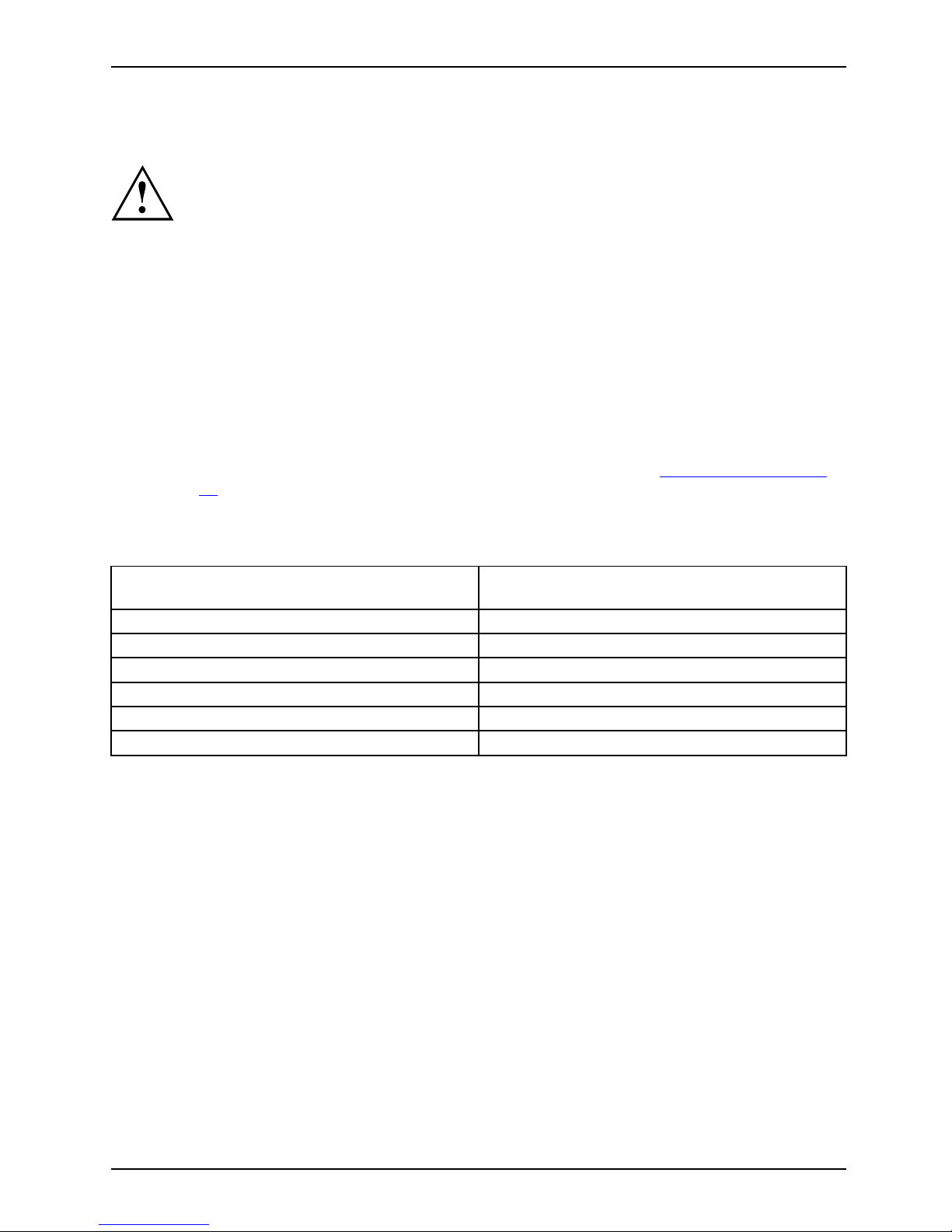
Before putting it into operati
on, allow sufficient time for the device to acclimatise
to the operating environment:
Temperature difference (°C) (operating
surroundings/outside)
Acclimatisation time (hours) (minimum
values)
5
3
10
5
15
7
20 8
25 9
30 10
A26361-K1182-Z120-1-7619, edition 3 9
Page 20
Getting started
Connecting external devices
Read the documentation on the external device before connecting it.
With the exception of USB devices, always remove all power plugs
before connecting external devices!
Do not connect or disconnect cables during a th understorm.
Always take hold of the actual plug. Never unplug a cable by pulling the cable itself.
Connect and disconnect the cables in the order described below.
Connecting the cables
► Turn off all power and equipment switches.
CordCable,
► Remove all power plugs from the grounded mains outlets.
► Connect all the cables to the device and the external devices. Please make sure that you
always observe the safety notes provided in "
Important notes", Page 4.
► Plug all data communication cables into the appropriate sockets.
► Plug all power cables into the grounded mains outlets.
USB devices are hot-pluggable. This means you can connect and disconnect
USB cables while your device is switched on.
Additional information can be found in "
Connecting external devices to the USB
ports", Page 14 and in the documentation for the USB devices.
Disconnecting the cables
► Turn off all power and equipment
switches.
Cable,
► Remove all power plugs from the grounded mains outlets.
► Unplug all data communication cabl
es from the appropriate sockets.
► Disconnect all of the cables from the device and from the external devices.
10 A26361-K1182-Z120-1-7619, edition 3
Page 21
Getting started
Ports on the device
PortsExternaldevicesDevice
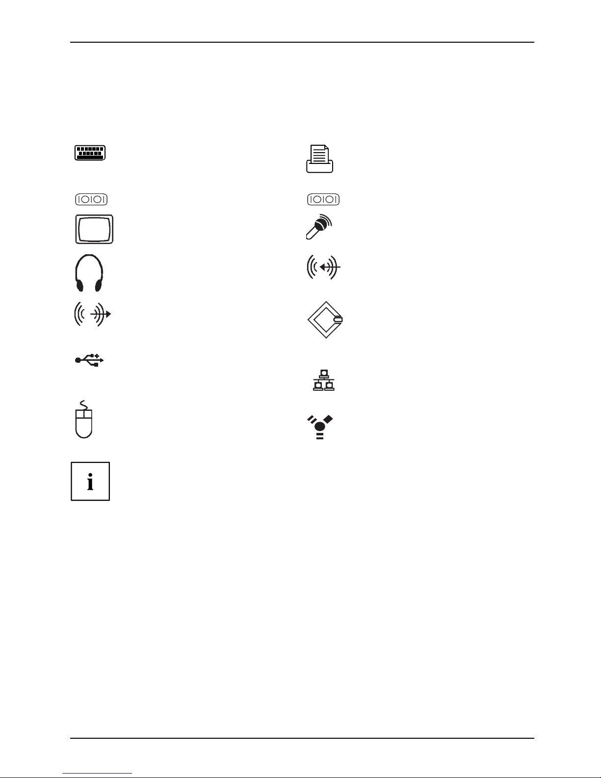
The ports are located on the front and back of the device. Not all ports are necessarily present on
your device. The standard ports are marked with the symbols shown below (or sim ilar). Detailed
information on the location of the connections is provided in the manual for the mainboard.
PS/2 keyboard port,
purple
Keyboardport
Parallel port/Printer,
burgundy
ParallelinterfacePrinter
1
Serial port 1, turquoise
Serialport
2
Serial port 2, turquoise
Serialport
Monitor port, blue
Monitorport
Microphone jack
(mono), pink
Microphoneport
Headphones port,
orange or light green
Наушники
Audio input (Line in),
light blue
AudioinputLinein
Audio output (Line out),
light green
AudiooutputLineout
SCSI connection
SCSIconnectionSCSI
USB - Universal Serial
Bus, black
UniversalSerialBus
LAN
LAN port
LANport
PS/2 mouse port,
green
MouseportPS/2mouseport
1394
FireWireTM,grey
FireWire
Some of the connected devices require special drivers (see the
documentation for the connected device).
A26361-K1182-Z120-1-7619, edition 3 11
Page 22
Getting started
Connecting the monitor
► Follow the instructions contained in the monitor manual to prepare the monitor
for operation (e.g. connecting cables).
Monitor,
► Connect the data cable of the monitor into the monitor port of y our device.
The monitor power cable may only be connected to the device monitor socket if
the monitor current consumption is le ss than 1.5 A for 230 V or 3 A for 115 V.
The values for th e monitor current consumption can be found in the technical
data on the monitor or in the operating manual for the monitor.
1
2
► Depending on your device configuration level, plug th e monitor power cable into
either the system unit (1) or a grounded mains ou tlet (2).
12 A26361-K1182-Z120-1-7619, edition 3
Page 23
Getting started
Connecting the mouse
You can connect a USB mouse or a PS/2 mouse to your device.
Mouse,Connecting,
Connecting a USB mouse
► Connect the USB mouse to one of the USB ports on the device.
USBport,USB port
Connecting a PS/2 mouse
If you do not attach a mouse to the PS/2 mouse port, you can disable the mo use
controller in the BIOS Setup in order to free the IRQ12 for a different application.
► Connect the PS/2 mouse to the PS/2 mouse port of the device.
PS/2mouse,Connecting,PS/2mouse,
Connecting the keyboard
You can connect a USB keyboard or a PS/2 keyboard to your device.
Keyboard,Connecting,
Connecting a USB keyboard
Use the supplied keyboard ca ble only.
USBport,Connecting,
► Plug the rectangular connector of the keyboar
d cable into the rectangular socket
on the underside or on the rear of the keyboard
.
► Insert the flat rectangular USB plug of the keyboard cable into one of the device’s USB ports.
USBport
Connecting a PS/2 keyboard
Use the supplied keyboard ca ble only.
ConnectingaPS/2keyboardConnecting,
► Plug the rectangular connector of the keyboard cable into the rectangular socket
on the underside or on the rear of the keyboard.
► Plug the round plug of the keyboard cable into the
keyboard port on the device.
Keyboard,
Connecting external devices to th e parallel or serial port
Parallelp
ort
SerialportParallelp
ort
SerialportExternald
evices
Devices
External devices can be connected to the parallel or serial port (e.g. a printer or a modem).
► Connect the data cable to the external device.
► Depending on the device, connect the data cable to the parallel port or the serial port.
For an exact description of how to connect external devices to the corresponding
port, please see the external device documentation.
Port settings
ParallelportSerialport,
You can change the port settings (e.g. address, interrupt) in the BIOS Setup.
A26361-K1182-Z120-1-7619, edition 3 13
Page 24

Getting started
Device drivers
DevicedriversDevice drivers,
The devices connected to the parallel or s erial port require drivers. Your operating
system already includes many drive rs. If the required drive is missing, install it. Current
drivers are usually available on the Internet or will be supplied on a d ata medium.
Connecting external devices to the USB ports
USBdevices,USBport,Externaldevices,Devices,
You can connect a wide range of external devices to the USB ports (e.g.
printer, scanner, modem or keyboard).
USB devices are hot-pluggable. This means you can connect and disconnect
USB cables while your device is switched on.
Additional information can be found in t he documentation for the USB devices.
► Connect the data cable to the external device.
► Connect the data cable to one of the USB ports on your device.
Device drivers
The external USB devices you conn ect to the USB p o rts usually require no
driver of their own, as the required software is already included in the operating
system. However, if the external USB device requires its own software, please
install it from the data carrier provided with the USB device.
To ensure USB 2.0, the length of the cable used between the front USB port of
your device and the external USB device must not exceed 3 m.
14 A26361-K1182-Z120-1-7619, edition 3
Page 25

Getting started
Connecting the device to the mains voltage
(device-dependent)
Device,Connecting,Device,
The device is adjusted to the mains voltage depending on the configuration level:
• On devices with a WAN component, the voltage supply is automatically
adjusted t o the mains v oltage.
• On devices with a voltage selector switch (sliding switch, plug-in element)
you will need to manually select the correct voltage rating.
100 V - 127 V
200 V - 240 V
115
230
1
a
a
100 V - 127 V
200 V - 240 V
230
115
2
230
115
1 = Sliding voltage switchover switch
2 = Plug-in voltage switchover element
a = Notch for inserting the screwdriver
The visible value must correspond to the local mains voltage:
• 115 = 100 V to 127 V
• 230 = 200 V to 240 V
► Check the voltage settin
g.
► If the incorrect mains voltage is selected, push the slide switch all the way into
the other available position (1) with a pointed object.
or
► Insert a screwdriver into the notch and prise out the plug-in element,
turn it and refit it the other way round (2).
A26361-K1182-Z120-1-7619, edition 3 15
Page 26

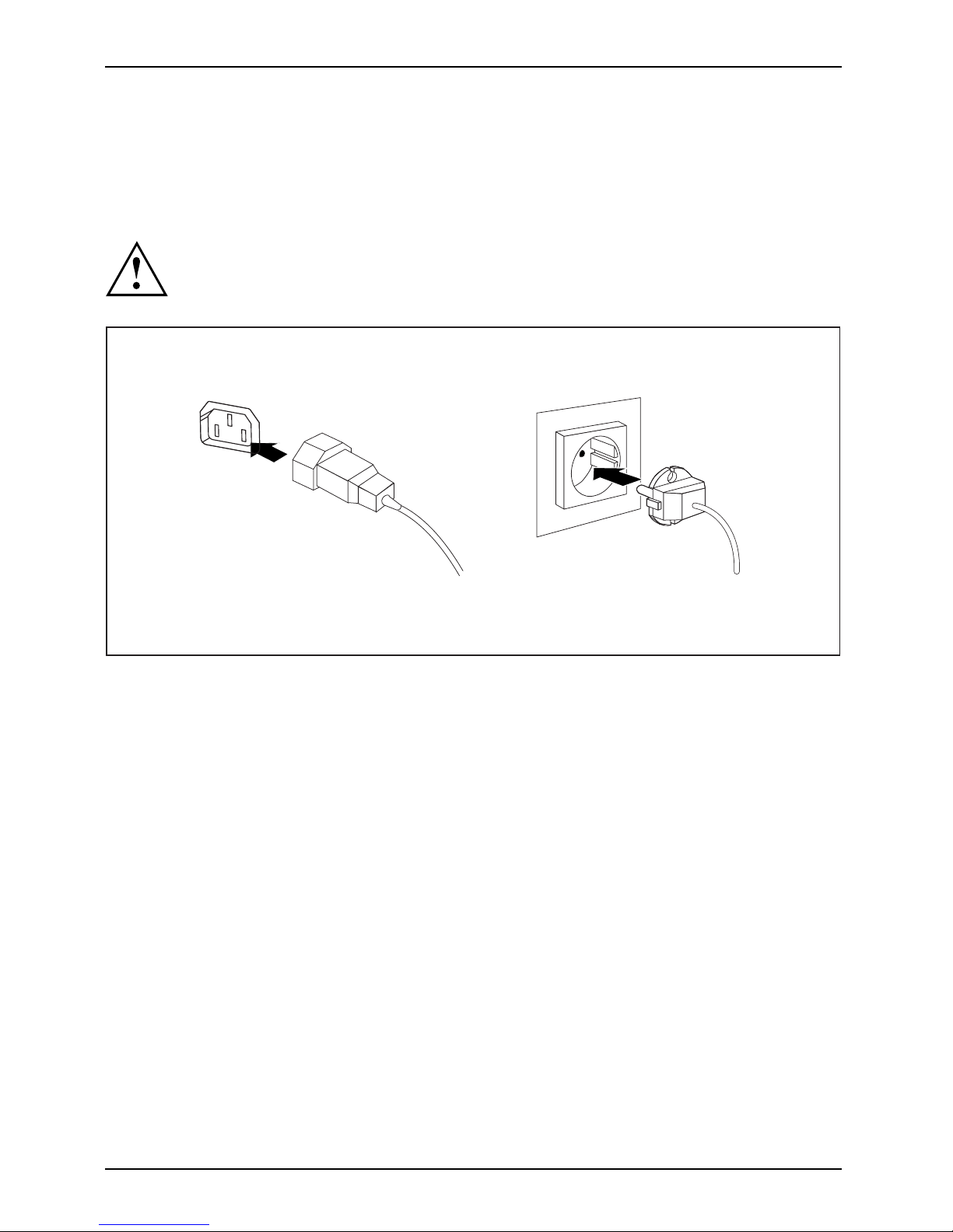
Getting started
2
1
► Connect the power cable to the device (1).
► Plug the power plug into a grounded mains outlet (2).
Switching on monitor and device
Device,Monitor,
Depending on the version, the device may be equipped with a main power switch
on the back of the device in addition to the ON/OFF button on the front. As a
result, there are different ways to switch on the two variants.
► Switch the monitor on (see the operating manual for the mo nitor).
► Switch the device on. To
do this, follow the instructions below.
16 A26361-K1182-Z120-1-7619, edition 3
Page 27

Getting started
Switching on the device (with main power switch)
0
1
2
I
0 = Device is off I = Device is on
► Switch the device on with the main power switch (1) on the back of the device.
► Press the ON/OFF switch (2) on the front of the device.
The power-on indicator lights green and the device is started.
A26361-K1182-Z120-1-7619, edition 3 17
Page 28

Getting started
Switching on the device (without main power switch)
► Press the ON/OFF switch on the front of the device.
The power-on indicator lights green and the device is started.
Installing the soft
ware
Configure the server and install the desired operating s ystem and applications.
This can be done in one of the following wa ys:
• Remote configuration and installation with ServerStart:
The included "ServerStart" CD makes it easy for you to configure the server
and then install the operating system.
•Localconfiguration and installation with or without ServerStart (see "
Configuring with ServerStart
or EasySetup", Page 23 or "Configuration without ServerStart", Page 23).
Installation with ServerStart
► Switch th e device on.
► Place the "ServerStart" CD or an installation disk in the corresponding drive.
► Follow the instructions on the screen (see "
Configuring with ServerStart or EasySetup",
Page 23 or "Configuration without ServerStart" , Pa ge 2 3).
For instructions on how to operate ServerStart and further information, refer to the
"ServerView Suite - ServerStart " manual supplied as a PDF fi le.
For advice on configuration, see "
Configuring with ServerStart or EasySetup", Page
23. If the device is integra ted into a network, the user and server details as well
as the network protocol are required during the software i nstallation.
For further information about the device and its drivers, utilities and
updates please refer to the "Drivers & Utilities" DVD or visit our website
at "
http://www.fujitsu-siemens.com/support".
18 A26361-K1182-Z120-1-7619, edition 3
Page 29

Operation
Operation
Switch the device on
► If necessary, switch the monitor on (see the operating manual for the monitor).
Device,Monitor,
► Switch on the device using the main
power switch locate d on the rear of the device (if present).
► Press the ON/OFF switch on the front of the device.
The power-on indicator lights gr
een and the device is started.
Switching off the device
► Shut down the operating system in a defined manner. In Windows: via the
Start menu a nd the Turn Off C omputer function.
Device,Monitor,
► If the operating system does not au
tomatically switch the device into energy-saving
mode or switch it off, press the ON
/OFF switch.
If the device is in standby, it consumes a minimum of energy.
► Switch the device off at the main swi
tch (if present). The device no longer uses any power.
The main switch and the ON/OFF swit
ch do not disconnect the device
from the mains voltage. To comple
tely disconnect the mains voltage,
remove the power plug from the p
ower socket.
► If necessary, switch the monitor off (see the operating manual for t he monitor).
A26361-K1182-Z120-1-7619, edition 3 19
Page 30

Operation
Other ways of switching on and off
As well as the On/Off switch, the device can be turned on or off in the following ways:
On/Off method Description
Preset On/Off time
Using the ServerView program you can set a time
in the future when the server will automatically
be turned on or off.
Ring indicator The device is switched on via an internal or
external modem.
Wakeup On LAN (WOL)
The device is s witche d on by a command sent
via the LAN.
After power failure
A switched-on device is automatically restarted
after a power failure (depending on the BIOS
setting).
"Power override" function The device can be turned off by pressing the
On/Off switch "firmly"foralongperiod(4-5
seconds).
Data may be lost when using the "power override" function!
Indicators on the device
Indicators,Device,
The indicators are on the front of the casing. Which indicators are available on your
device dep ends on the configuration level you have selected.
3
1
2
4
1 = Drive indicator, e.g. DVD
2 =Floppydiskin
dicator
3 = Hard disk indicator
4 = Power-on indi
cator
20 A26361-K1182-Z120-1-7619, edition 3
Page 31

Operation
Hard disk ind icator
The indicator lights up when the device’s hard disk is accessed.
Power indicator
PowerindicatorPowerindicator,Powerindicat or,Powerindicat or,Pow er indicator,
In energy-saving m ode, the device m ust not be switched off with the main power switch
(if present) or disconnected from the mains, as this may result in data loss.
• The indicator is green: the device is on.
• The indicator flashes green:The system is in power-saving mode. After being
switched on with the On/Off switch, the device switches on or returns to the state
it was in before it went into powe r-saving mode.
• Indicator does not light up: Device is switched off and disconnected from the power supply.
Floppy disk indicator
Floppydiskdrive,
The indicator lights up when the floppy disk drive of the device is accessed. You may
only remove the floppy disk when the indicator is unlit.
Drive indicator, e.g. DVD
DVDindicatorDVDindicator,CD-ROMindicatorCD-ROMdrive,
The indicator lights u p when the CD-ROM or DVD drive is accessed. You may only
remove the CD/DVD when the indicator is not on.
Keyboard
KeyboardKeyboard,Keyboard,Keyboard,Keyb oard,Keyboard,Alphanumeric keypadCursorkeysKeys,FunctionkeysNumerickey padNumeric keypad
1 2
345
1 = Function keys
2 = On/off switch (optional)
3 = Alphanumeric keypad
4=Cursorkeys
5 = Numeric keypad (ca lculator keypad)
A26361-K1182-Z120-1-7619, edition 3 21
Page 32

Operation
The illustrated keyboard is an example and may differ from the model you use.
Important keys and keyboard sho
rtcuts
KeysKeyboardshortcuts
The description of the following keys and keyboard shortcuts applies to Microsoft
operating systems. Details of other keys and keyboard shortcuts can be found in
the documentation for the relevant application program.
ON/OFFswitchButton,
On/off switch (optional)
Depending on the setting in the BIOS Setup, the device can be
switched on or off with this switch. Some operating systems allow
you to configure additional functions of the ON/OFF switch in the
Control Panel.
With some keyboards the ON/OFF switch can only be used with an
ACPI (Advanced Configuration a nd Power Management Interface).
Otherwise the key is inoperative. The mainboard must support this
function.
Keys,Keys,Keys,
Enter key
confirms the highlighted selection. The Enter key is also referred to
as the "Return" key.
Start key
Keys,
calls up the Windows Start menu.
Keys,
Menu key
calls up the menu for the marked item (Windows).
Keys,Keys,
Shift key
enables upper-case letters and the upper key symbols to be displayed.
Keys,
Alt Gr key
produces a character shown on the bottom right of a key (e.g. the @
sign on the
Q
key).
Keys,
Num Lock key
By pressing the Num Lock key you switch between the upper- and
lower-case levels of the calculator keypad.
When the Num Lock indicator is lit the numeric keypad and arithmetic
keys are active.
When the Num Lock indicator is not lit the cursor control functions on
the Numeric keypad a re active.
22 A26361-K1182-Z120-1-7619, edition 3
Page 33

Operation
Ctrl
Keys,Keys,Keys,Keys,
Ctrl key
performs a special operation when pre
ssed in conjunction with another
key. The
Ctrl
keyisalsoreferredtoas"Con
trol" or the "Control key".
AltCtrl
Del
SysRq
++
WarmrebootCtrl+Alt+DelKeys,keyboardshortcuts
Warm restart
restarts your device. Press simultaneously the keys
Ctrl,Alt
and
Del
.
Under some operating systems the Task Manager appears first. You
must then press all three keys again to reboot.
Configure device
Configuration
This section contains information about the configuration of the device and
installation of the operating system.
Make sure the energy saving functions are disabled in the BIOS Setup.
Configuring with ServerStart or EasySetup
These applications makes it easy for you to configure the device and then install the operating system.
The menu-driven configuration process includes server configuration with SCU
and RAID controller configuration.
Information about using ServerStart can be found in the "PRIMERGY ServerView
Suite - ServerStart" manual on the "ServerStart" CD.
Further information abou t using EasySetup is provided on the "Drivers & Utilities" DVD.
Configuration without ServerStart
► First configure the SATA RAID controller (see "Configuring the SATA RA ID controller", Page 24).
► Insert the installation disk and t
he CD/DVD of the operating system you want to install.
► Restart the device.
► Follow the instructions on the scre
en and in the manual for the operating system.
► If your device is equipped with a RAID co ntroller, refer to its manual to find out how t o
install the desired operating system (see "
Information sources", Page 3).
A26361-K1182-Z120-1-7619, edition 3 23
Page 34

Operation
Configuring the SATA RAID controller
ConfigurationSATARAIDcontroller
A SATA RAID controller is integrated on the mainboard to which multiple SATA hard drives can
be connected. RAID levels 0 and 1 are supported by SATA RAID software.
You c a n co nfigure the RAID controller either before or during configuration with ServerStart
or EasySetup. Use of the supplied software is recommended.
The controller has its own configuration utility.
Further information can be found in the RAID software manual on
the "Drivers & Utilities" DVD.
Settings in BIOS Setup
BIOSSetup,System settings,BIOS Setup,BIOSSetup,BIOSSetupSetup,
In BIOS Setup, you can set t he system functions and the hardware configuration of the device.
When the PC is delivered, the default entries are valid (see "BIOS Setup" manual or manual for
the main board). You can customise these settings to your requirements in the BIOS Setup.
24 A26361-K1182-Z120-1-7619, edition 3
Page 35

Property and data protection
Property and data protection
PropertyprotectionDataprotectionSecu ritymeasures
Software functions and mechanical locking offer a broad range of functions for protecting your
device and your personal data from unauthorised access. You can also combine these functions.
Mechanical access protection
Detection of unauthorised opening
The server is equippe d with a device to detect unauthorised opening of the casing (Intrusion
Detection Switch). With the help of this detector, the ServerView pro gram is able to recognise when the
cover of the device is removed without authorisation and generates a corresponding alarm message.
A26361-K1182-Z120-1-7619, edition 3 25
Page 36

Property and data protection
Mechanical casing lock (optional)
CasingmechanicallockCasingLockCasing lock
With the casing lock you can m echanica lly lock the casing to prohibit unauthorised persons
from opening it. T he keys can be found on the rea r panel of your device.
2
1
Locking the casing
► Turn the ke y in the direction of the arrow (1).
Unlocking the casing
► Turn the ke y in the direction of the arrow (2).
26 A26361-K1182-Z120-1-7619, edition 3
Page 37

Property and data protection
Anti-theft protection and lead-sealing
Device,Device,Casi ng,Lead-sealingAnti-theftprotectionKensington LockChain
1
2
1 = Holes for padlock 2 = Device for "Kensington Loc
k"
Anti-theft protection
You can protect your devic
efromtheft
• with the holes (1), a padlo
ck and a chain, which you have connected to a fixed object beforehand.
• with the Kensington Lock device (2) and a Kensington MicroSaver. Consult
the manu al for your Kensington Lock.
Lead-sealing
The casing can be sea led to prevent it being opened by unauthorised persons. To do this, feed
the sealing chain through the holes (1) and seal the chain with the lead seal.
A26361-K1182-Z120-1-7619, edition 3 27
Page 38

Property and data protection
BIOS setup security functions
Securityfunctions,BIOSSetup,
The Security menu in BIOS Setup offers you various options for protecting your
personal data aga inst unauthorized access, e.g.:
• Preventing unauthorised access to BIOS Setup
• Preventing unauthorised system access
• Preventing unauthorised access to the settings of boards with their own BIOS
• Preventing the system from booting from the diskette drive
• Issuing virus warnings
• Preventing the unauthorised writing of floppy disks
• Protecting BIOS from overwriting
• Protecting the device from being switched on by an external device
You can also combine these functions.
You will find a detailed description of the Security menus and how to a ssign passwords
in the manual for the mainboard or in the "BIOS Setup" manual.
Access authorisation via external SmartCard reader
Securityfunctions,Accesspermission,SmartCard
In systems equipped with an external SmartCard reader, access can be restricted
to those users who have a corresponding SmartCard.
28 A26361-K1182-Z120-1-7619, edition 3
Page 39

Property and data protection
Access protection with SystemLock
Securityfunctions,Securityfunctions,
With SystemLock, you can protect your system from unauthorised booting. A system can then only
be booted when the user inserts a valid SmartCard into the SmartCard reader and enters his/her
personal code number (PIN). To use SystemLock, you require the following components:
• External SmartCard reader
• Syste m Lock installed (see "BIOS Setup" manual)
• SmartCard
SystemLock controls access to your device. W hen a SmartCard is initialised, permissions
are assigned for system access (system, setup, system+setup, admin). You can configure
several SmartCards for one system and initialise them with different permissions. In
addition, you can protect access to your hard disk
In this way users can be divided into user groups. Users of a user group
use SmartCards with the same permissions.
If you also want to use other security software in addition to SystemLock (e.g. SMARTY),
please read your security software documentation beforehand.
SystemLock rights
You can initialise a SmartCard with on e of the following rights:
System The system starts following entry of the user PIN. You can change the user
PIN.
Setup
You can open and change the BIOS Setup and change the user PIN.
System+Setup The system starts following entry of the user PIN. You can open and change
the BIOS Setup and change the user PIN.
Admin
The system starts following entry of the user PIN. You can change the user
PIN and the administrator PIN, unlock locked SmartCards, open and change
the BIOS Setup and generate additional SmartCards for this system.
For instructions on how to install and use SystemLock, and how to initialise
SmartCards, see the "BIOS Setup" manual.
Operating the SmartCard reader
► Connect the external SmartCard reader to your system as described in
the instructions for the SmartCard reader.
SmartCardreader,
After the device is switched on, you will be prompted to insert your SmartCard.
A26361-K1182-Z120-1-7619, edition 3 29
Page 40

Troubleshooting and tips
Troubleshooting and tips
Refer to the safety notes in the "Safety" manual and in the "Gett ing started",
Page 8 chapter when connecting or disconnecting cables.
If a fault occurs, try to correct it as described in the following documentation:
• in this chapter
• in the documentation for the connected devices
• in the he lp systems of the software used
• in the documentation for your operating system
If you fail to correct the problem, proceed as follows:
► Switch the device off.
► Make a note of the steps and t he circumstances that led to the fault.
► Make a note of any error messages displayed.
► Note the ID number of your device. The ID number can be found on the
type rating plate on the ba ck of the casing.
► Please contact your sales outlet or our service department (refe r to the enclosed Help
Desk List or go to "
http://www.fujitsu-siemens.com/support/").
Troubleshooting
Power indicator remains off after you have switched
on your device
Cause
Remedy
The mains voltage supply is faulty. ► Check whether the power cable is properly
plugged into the device and a grounded
mains outlet.
► Switch the device on.
Internal power supply over
loaded.
► Pull the power plug of the device out of the
mains outlet.
► Wait a moment.
► Plug the power plug into a properly ground ed
mains outlet again.
► Switch the device on.
30 A26361-K1182-Z120-1-7619, edition 3
Page 41

Troubleshooting and tips
The device cannot be switched off with the ON/OFF switch.
Cause
Remedy
The de vice has not been switched on with the
ON/OFF switch.
► Press th e ON/OFF switch again.
System crash ► Press the ON/OFF switch for at least
4 seconds, until the device switches off.
The operating system is not shut-down properly
in the process. Error messages are therefore
possible the next time the system is booted.
Monitor remains blank
Cause
Remedy
Monitor is switched off. ► Switch your monitor on.
Power saving has been activated (screen is
blank)
► Press any key on the keyboard.
or
► Deactivate the screen saver. If
necessary, e nter the appropriate
password.
Brightness control is se t to dark ► Adjust the brightness control. For detailed
information, please refer to the operating
manual supplied with your monitor.
Power c able not connected
► Switch off the monitor and the device.
► Check that the monitor power cable is
properly connected to the monitor and to
a grounded mains outlet or to the monitor
socket of the device.
► Check that the device power cable is
properly plugged into the device and a
grounded mains outlet.
► Switch on the monitor and the device.
Monitor cable not connected
► Switch off the monitor a
nd the device.
► Check that the monitor cable is properly
connected to the device and monitor.
► Switch on the monitor and
the device.
A26361-K1182-Z120-1-7619, edition 3 31
Page 42

Troubleshooting and tips
No mouse pointer displayed on the screen
Cause
Remedy
The mouse is not correctly connecte d.
► Shut down the operating system properly.
► Switch the device off.
► Check that the mouse cable is properly
connected to the system unit. If you use an
adapter or extension lead with t he mouse
cable, ch eck the connections.
► Make sure that only one mouse is
connected.
► Switch the device on.
Mouse driver not loaded.
Check whether the mouse driver is properly
installed and activated.
Detailed information can be found in the
documentation supplied for the mouse,
operating system or application software.
Mouse controller on the main board not switched
on.
► In the BIOS-Setup, check the settings
in the Advanced menu under Peripheral
Configuration, Mouse Controller.
► If necessary, change the set
ting to Enabled
or Auto Detect.
The floppy disk cannot be r
ead or written
Cause
Remedy
The write protection of the floppy disk or the
floppy disk drive is activated.
► Check whether the write protection of
the floppy disk or the floppy disk drive is
activated (refer to the "BIOS Setup" manual
and if necessary to the manual for the
mainboard).
The floppy disk drive controller is not enabled. ► Check the relevant entries for floppy disk
driveintheMain menu of the BIOS Setup.
► Check that the flopp y disk drive controller
is enabled (refer also to the manual for the
mainboard or in the "BIOS Setup" manual).
The floppy disk drive is not connected. ► Check that the cables of the floppy disk
drive are properly connected.
32 A26361-K1182-Z120-1-7619, edition 3
Page 43

Troubleshooting and tips
Drives at system start "de ad"
Cause
Troubleshooting
Configuration of R AID controller incorrect ► Check the drive settings with the RAID
controller utility.
For further information, refer to "
Configuring
the SATA RAID con troller", P age 24 and the
RAID controller manual (see "
Information
sources", Page 3).
► Change the settings if necssary.
Added drive faulty
Cause
Troubleshooting
RAID controller not configured for drive ► Configure the drive with the utility for the
RAID controller.
For further information, refer to "
Configuring
the SATA RAID con troller", P age 24 and the
RAID controller manual (see "
Information
sources", Page 3).
► If the drive is still faulty, replace it (see
"
Installing and removing drives" , Page 52).
Time and/or date is not correct
Cause
Troubleshooting
Time and date are wrongly set.
► Set the correct time and date within the
operating system you are using.
or
► Set the correct time and/or date in the
BIOS Setup.
The on-board lithium battery in the device is flat. If the time and date are repeatedly wrong when
you switch on your server, the battery is flat.
Change the lithium battery as described in the
manual for the mainboard.
Error messages on the screen
Error messages and their explanations are provided:
• in the "BIOS Setup" manual
• in the technical manual for the mainboard
• in the documentation for the programs u sed
A26361-K1182-Z120-1-7619, edition 3 33
Page 44

Troubleshooting and tips
Installing new software
When installing programs or drivers, important files may be overwritten and modified. To
be able to access the original data in the event of any problems following installation,
you should backup your hard disk prior to installation.
34 A26361-K1182-Z120-1-7619, edition 3
Page 45

System expansions
System expansions
Upgrades,Device,Systeme xpansion
As the device has to be shut down in order to install/uninstall system hardware
components, it is a good idea to print out the relevant sections of this chapter.
It may be necessary to update the BIOS when carrying out a system expansion
or hardware upgrade. Additional information is contained in the "BIOS Setu p"
manual or possibly in the technical manual for the mainboard.
When installing components that become very hot, make sure that the
maximum p ermissible temperature is not exceeded.
The device must be switched off when installing/removing the system
expansions and may not be in energy-saving mode.
Remove the po wer plug before opening the device.
This chapter describes all the activities required to modify your device hardware
(e.g. installing boards or drives).
Read the supplied documentation before installing new drives and/or boards.
Refer to the manual for the mainboard before making any extensions to the mainboard.
A26361-K1182-Z120-1-7619, edition 3 35
Page 46

System exp ansio ns
Information about boards
Take care with the locking mechanisms (catches and centring pins) when you
are replacing boards or co m ponents on boards
To prevent damage to the board or the components and conductors on it, please take care when
you insert or remove boards. Make sure expansion boards are inserted straightly.
Never use sharp objects (screwdrivers) for leverage.
Boards with electrostatic se
nsitive devices (ESD) are identifiable by the label
shown.
When handling boards fitted wi
th ESDs, you must always observe the
following points:
• You must always discharge sta
tic build up (e.g. by touching a grounded
object) before working.
• The equipment and tools you use must be f ree of static charges.
• Only touch or hold the boards
by the edge or at the areas marked green
(Touch Points).
• Never touch pins or conductors on boards fitted with ESDs.
• Disconnect the mains plug bef
ore inserting or removing components.
• When installing components, use a suitable earthing cable to connect
them to a bare metal (i.e. unpainted) part of the system unit which does
not carry a live voltage.
• Place down all components on
asurfacewhichisfreeofstaticcharge.
A detailed description of how to protect sensitive components from the
effects of electrostatic discharge can be found in the relevant European and
international standards (EN 61340-5-1, ANSI/ESD S20.20).
36 A26361-K1182-Z120-1-7619, edition 3
Page 47

System expansions
Opening the casing
Cover removal
Casing,Device,
► Switch the device off. The device must not be in energy-saving mode.
Please observe the safety information in "Important notes", Page 4.
Unplug the mains plug from the ma
ins outlet.
Do not insert the power plug until you have closed the casing.
► Remove any plugged-in cables that are in the way.
► On devices with a casing lock: Unlock t he casing.
► Lay the device on its side in the manner shown below.
1
2
► Pull the locking device
(1) and swivel the side part in the direction of the arrow (2).
A26361-K1182-Z120-1-7619, edition 3 37
Page 48

System exp ansio ns
Opening t he drive cage
► Remove the device cover ("Cover removal", Page 37).
2
1
► Unscrew the knurled screw (1).
► Fold open the drive cage (2).
Thanks to the integrate d torque controller the drive cage will stop in any position.
38 A26361-K1182-Z120-1-7619, edition 3
Page 49

System expansions
Closing the casing
Closing the drive cage
When closing the drive cage, take care not to trap any cables.
2
1
► Close the drive cage (1).
► Secure the drive cage with the knurled screw (2).
A26361-K1182-Z120-1-7619, edition 3 39
Page 50

System exp ansio ns
Attaching the cover
1
► Insert the side part in the guide rail on the lower part of the casing.
Casing,Device,
► Swivel the side part in the direction of the arrow (1) until it engages.
► Ondeviceswithacasinglock: Lockthecasing.
► Reconnect the cables that you disconnected previously.
40 A26361-K1182-Z120-1-7619, edition 3
Page 51

System expansions
Installing the locking device w
ith casing lock
Removing the locking device
► Open the casing (see "Opening the casing", Page 37).
► Place the removed side part on a flat surface with the inside facing upwards.
1
1
2
► Press the catch in the direction of the arrow (1).
► Carefully thread the locking device out of the side part in the direction of the arrow (2).
A26361-K1182-Z120-1-7619, edition 3 41
Page 52

System exp ansio ns
Installing the locking device with casing lock
2
2
3
1
► Turn the removed side part over (so that the outside faces upwa rds).
► Guide the locking device with the casing lock in the direction of the arrow ( 1) into the side part.
► Press the catch in the direction of the arrow (2) and at the same time press the
locking device into the side part (3) until the catch engages.
42 A26361-K1182-Z120-1-7619, edition 3
Page 53

System expansions
Removing ventilation duct
Ventilationduct,
When removing the ventilation duct, be careful not to damage the
processor cooler(s) on the mainboard.
1
2
► Open the casing (see "Opening the casing", Page 37).
► Unhook the wires from the holder on the ventilation duct.
► Remove any connected w ires which are in the way.
► Unlock the ventilation duct by pressing locking hooks in the direction of the arrow (1).
► Keep pressing the locking hook and pull the ventilation duct in the direction
of the arrow (2) out from the casing.
A26361-K1182-Z120-1-7619, edition 3 43
Page 54

System exp ansio ns
Ventilation duct installing
Ventilationduct,
When fitting the ventilation duct, be careful not to damage the
processor cooler(s) on the mainboard.
1
► Insert the latches on the underside of the ventilation duct into the co rrespon ding slots in the casing.
► Press the ventilation duct into the casing in the direction of the arrow (1)
so that the locking hook is felt to engage.
► Reconnect the cables that you disconnected previously.
► Hook the wires into the holder on the ventilation duct.
► Close the casing (see "
Closing the casi ng", Page 39).
44 A26361-K1182-Z120-1-7619, edition 3
Page 55

System expansions
Installing and removing heat si
nks
Removing heat sinks
► Remove the ventilation d uct (see "Removing ventilation duct", Page 43).
► Disconnect the cables to the heat sink.
1
1
1
1
2
► Loosen the screws (1)
.
► Lift the heat sink out of the casing (2).
A26361-K1182-Z120-1-7619, edition 3 45
Page 56

System exp ansio ns
Installing heat sinks
2
2
2
2
1
► Insert the heat sink into the casing (1). To do this, correctly align the screw holes
on the heat sink with the screw holes on the mainboard.
► Fasten the screws (2).
► Connect the cables to the heat sink.
► Install the ventilation duct again (see "
Ventilation duct installing", Page 44).
Installing and removing additional fans (devices
with four hard disk
s)
An additional fan is only included in devices that can be fittedwithfourharddiskdrives.
46 A26361-K1182-Z120-1-7619, edition 3
Page 57

System expansions
Removing additional fans
1
3
2
► Press the catch down (1).
► Lift the fan up at both sides a nd pull slightly
backwards (2) to release the clip on the fan.
► Pull the fan in the dire ction of the arrow (3).
► Disconnect the ca bles to the fan.
► Lift the fan out of the device.
Installing additional fans
2
1
► Connect the cables to the fan.
► Insert the fan into the casing (1). Ensure
that the clip on the fan is inserted into the
two corresponding slots in the casing.
► Press on the catch and ensure that the
fan clicks audibly into the casing (2).
A26361-K1182-Z120-1-7619, edition 3 47
Page 58

System exp ansio ns
Installing and removing a board
The number, position and arrangement of the board slots on the mainboard can be found in
the manual for the mainboard. Boards may already be installed on shipment.
Board,Board,
Remove the slot cover.
► Open the casing (see "Opening the casing", Page 37).
1
2
► Loosen the screw (1).
► Pull the slot cover out of the slot (2).
Do not throw away the slot cover. For cooling, p rotection against fire and in order to
comply with EMC regulations, you must refit the slot cover if you remove the board .
48 A26361-K1182-Z120-1-7619, edition 3
Page 59

System expansions
Installing a board
2
1
► Push the board into the slot (1)
until it enga ges.
► Fasten the screw (2).
► If necessary, connect the cables to the board.
If you have installed or removed a board, please check the relevant PCI
slot settings in the BIOS Setup. If necessary, change the s ettings. Further
information is provided in the PCI board documentation.
Removing boards
► If necessary, disconnect the cables which are connected t o the board.
2
1
► Loosen the screw (1).
► Pull the board out o f the slot (2).
► Place the board in suitable packaging.
A26361-K1182-Z120-1-7619, edition 3 49
Page 60

System exp ansio ns
Reinstalling a slot cover
For cooling, protection against fire, and in order to comply with EMC (electromagnetic
compatibility) regulations, you must refit the slot cover.
2
1
► Push the slot cover into the slot (1).
► Tighten the screw (2).
► Close the casing (see "
Closing the casi ng", Page 39).
If you have installed or removed a board, please check the releva nt PCI
slot settings in the BI OS Setup. If necessary, change the settings. Further
information is provided in the PCI board documentation.
50 A26361-K1182-Z120-1-7619, edition 3
Page 61

System expansions
Low-profile boards
Low-profileboard
You will need to fit a corresponding slot adapter first before you can install a
low-profile board in a normal board slot.
Two-piece slot covers are fitted to the slots intended for low-profile boards. The
two pieces are joined together by a screw.
Do not throw away the slot cover. For cooling, protection against fireandinorderto
comply with EMC regulations, you must refit the slot cover if y ou remove the board.
EMC,electromagneticcompa tibility
► Remove the required slot cover (see "Installing and removing a board", Page 48).
Fitting a slot adapter
2
1
► Fit the slot adapter to the slot cover of the low-profile board (1) and screw tight (2).
Low-profi
leboards,
Now you can install the low-profile board in a suitable slot like a normal board
(see "
Installing and removing a board", Page 48).
A26361-K1182-Z120-1-7619, edition 3 51
Page 62

System exp ansio ns
Removing a slot adapter
2
1
► Unscrewthescrew(
1) and remove the slot adapter (2 ).
Low-profileboards,
Installing and removing drives
DriveDriveDriveDrive31/2-inchdrive51/4-inchdriveDrive
The casing can accommodate a total of seven drives:
• four accessible drives (two 5¼-inch drives and two 3½ -inch drives)
Depending on the device expa
nsion stage:
• two non-accessible drives (t
wo 3½-inch drives with half installation height)
or
• four non-accessible drives (four 3½-inch drives with half installation height)
"Accessible drives" are e.g.
DVD or CD ROM drives, into which a data medium can be
inserted from outside. Non-a
ccessible drives are e.g. hard disk drives.
The number of screws used to at
tach the drives varies according to the type of drive
fitted and may not necessarily
match the depiction b elow.
52 A26361-K1182-Z120-1-7619, edition 3
Page 63

System expansions
Installing and removing accessible drives
Removing an accessible 51/4inch drive (e.g. DVD drive)
► Open the casing (see "Opening the casing", Page 37).
Accessible drive,Drive,
► Disconnect all cables connected to the drive (data cable, power supply cable).
2
1
► Loosen the screws (1).
► Working from behind, slide the drive a short distance out of the bay in the direction of the arrow (2).
The drive now protrudes slightly out of the casing.
► Pull the drive out of the c asing (2).
► If necessary, make the required settings on the remaining hard disk drive.
► If you are not installing a new drive, close the opening with a cover.
► Close the casing (see "
Closing the casing", Page 39).
It may be necessary to modify the entry for the remaining drives in the BIO S Setup.
A26361-K1182-Z120-1-7619, edition 3 53
Page 64

System exp ansio ns
Installing an accessible 51/4inch d rive (e.g. DVD drive)
► Open the casing (see "Opening the casing", Page 37).
Accessible drive,Drive,
► Remove the cover.
Do not throw away the cover. For cooling, protection against fire, and in order to
comply with EMC regulations (regulations regarding electromagnetic compatibility),
you must refit the covers if you remove the drive again later.
► Take the new drive out of its packaging.
► Make the desired settings on the new drive (if necessary, to the settings of
drives already installed as well (Master/Slave)).
1
2
► Slide the drive into the casing as far as it will go (1).
► Fasten the drive in place with the screws (2).
► Plug the data and the power supply connectors into the drive. Make sure the polarity is correct.
In the case of improper use of the cutting tool, there is a risk of
injury and damage to th e casing.
Beware of sharp edges when cutting out the installation panel.
► If you a re installing a second drive, remove the cover (3) and then remove the
installation panel beneath it using a c utting tool.
► Close the casing (see "
Closing the casi ng", Page 39).
It may be necessary to modify th e entry for the drive in the BIOS Setup.
54 A26361-K1182-Z120-1-7619, edition 3
Page 65

System expansions
Installing and removing an accessible 31/2inch
drive (e.g. diskette drive)
► Open the casing (see "Opening the casing", Page 37).
Floppydiskdrive,Floppy diskdrive,
► Disconnect all cables connected to
the drive (data cable, power supply cable).
1
2
► Remove th e screws (1).
► Working from behind, slide the floppy disk drive out of the bay in the direction of the arrow (2).
2
1
► Slide the new floppy disk drive into the casing as far as it will go (1).
► Fasten the flopp
ydiskdrivewiththescrews(2).
► Fit the data and power supply connectors to the floppy disk drive. Make sure the polarity is correct.
A26361-K1182-Z120-1-7619, edition 3 55
Page 66

System exp ansio ns
In the case of improper use of the cutting tool, there is a risk of
injury and damage to th e casing.
Beware of sharp edges when cutting out the installation panel.
Do not throw away the cover. For cooling, protection against fire, and in order to
comply with EMC regulations (regulations regarding electromagnetic compatibility),
you must refit the covers if you remove the drive again later.
► If you are installing a second drive, push the cover (3) out of the casing and remove
the installation panel beneath it using a cutting tool.
► Close the casing (see "
Closing t
he casing", Page 39).
It may be necessary to modify th
e entry for the drive i n the BIOS Setup.
Installing and removing the hard disk drive
Harddiskdrive,Harddiskdrive,Harddiskdrive,
Removing a hard disk drive
► Open the casing (see "Opening the casing", Page 37).
Harddiskdrive,
► Disconnect all cables connected to the drive and fan (data cable, power supply cable).
56 A26361-K1182-Z120-1-7619, edition 3
Page 67

System expansions
The procedure described below is the same for all device expansion
stages (two or four hard disks).
1
2
1
► Slightly press together the EasyChange rails mounted on the hard disk (1) and pull the
hard disk drive out of the drive cage in the direction of the arrow (2).
► Pull the Ea
syChange rails off the hard d isk drive.
► If necessary, make the required settings on the remaining hard disk drive.
A26361-K1182-Z120-1-7619, edition 3 57
Page 68

System exp ansio ns
► Close the casing (see "Closing the casing", Page 39).
It may be necessary to modify the entry for the remaining drives in the BIOS Setup.
Installing a hard disk drive
► Open the casing (see "Opening the casing", Page 37).
Harddiskdrive,
► Take the new hard disk drive out of its packaging.
► Secure the EasyChange rails on the side of the hard disk by inserting the pins of the
EasyChange rail in the corresponding holes of the hard disk.
EasyChange rails for a second hard disk drive are mounted on the drive cage. You can
install the second hard disk drive in exactly the same way as described in this section.
58 A26361-K1182-Z120-1-7619, edition 3
Page 69

System expansions
The procedure described below is the same for all device expansion
stages (two or four hard disks).
1
► Slide the hard disk drive with the EasyChange rails in the direction of the arrow (1) into the drive
cage. Check that the component side of the hard disk drive faces inwards towards the casing.
► Connect the cables (data cable, power supply) to the drive and to the fan.
► Close the casing (see "
Closing the casing", Page 39).
Mainboard expansions
Details on how to upgrade the main memory or the processor of your device
can be found in the manual for the m ainboard.
UpgradesLith iumbatteryProcessorMainmemoryMainboard
Upgrading main memory
► Open the casing (see "Opening the casing", Page 37).
Mainmemory,
► Upgrade the memory according to the description in the manual for the mainboard.
► Close the casing (see "
Closing the casing", Page 39).
A26361-K1182-Z120-1-7619, edition 3 59
Page 70

System exp ansio ns
Replacing the processor
► Open the casing (see "Opening the casing", Page 37).
Processor,rep lacing
► Remove the ventilation duct (see "Removing ventilation duct", Page 43).
► Remove the heat sink (se e "
Removing heat sinks", Page 45).
► Upgrade the processor according to the description in the manual for t he mainboard.
► Fit the heat sink (see "
Installing heat sinks", Page 46).
► Install the ventilation duct (see "
Ventilation duct installing", Page 44).
► Close the casing (see "
Closing the casi ng", Page 39).
60 A26361-K1182-Z120-1-7619, edition 3
Page 71

Technical data
Technical data
Technicaldata
Data: electrical
Regulations complied with
IEC 60950-1, EN 60950-1, UL 60950 CSA 22.2
No.60950-1
Protection class I
Rated v oltage range (selectable) 100 V – 127 V / 200 V – 240 V
Rated frequency
50 Hz – 60 Hz
Maximum rated current (casing with monitor
socket)
100 V – 127 V / 6.5 A
200 V – 240 V / 3.5 A
Maximum rated current (monitor socket
(output)):
100 V – 127 V / 3.0 A
200 V – 240 V / 1.5 A
Dimensions
Width x d epth x height 203 mm x 387 mm x 390 mm
Weight
in basic configuration:
approx. 11 kg
Environmental conditions
Environment class ( 3K2) DIN IEC 721 part 3-3
Environment class ( 2K2) DIN IEC 721 part 3-2
Temperature:
Operating (3K2) 15 °C ... 35 °C
Transportation (2K 2) -25 °C ... 60 °C
Condensation must be avoided during operation.
The data sheet of the device contains further technical data. The data sh eet
can be found on our website "
www.fujitsu-siemens.com".
A26361-K1182-Z120-1-7619, edition 3 61
Page 72

Index
Index
Наушники 11
31/2-inchdrive 52
51/4-inchdrive 52
A
Access permission, SmartCard 28
Accessible drive,
installing 54
removing 53
Alphanumeric keypad 21
Anti-theft protection 27
Audio input 11
Audio output 11
B
BIOS Setup 24
BIOS Setup,
configuration 24
security functions 28
settings 24
system settings 24
Board,
installing 48
removing 48
Button,
ON/OFF switch 22
C
Cable,
connecting 10
disconnecting 10
Casing
Mechanical lock 26
Casing lock 26
Casing mechanical lock 26
Casing,
closing 40
lead-sealing 27
opening 37
CD-ROM drive,
indicator 21
CD-ROM indicator 21
CE marking 5
Chain 27
Configuration 23
SATA RAID controller 24
Connecting a PS/2 keyboard 13
Connecting,
device 15
keyboard 13
mouse 13
PS/2 keyboard 13
PS/2 mouse 1 3
USB keyboard 1 3
Contents of delivery 8
Cord
see Cable 10
Ctrl+Alt+Del 23
Cursor keys 21
D
Data protection 25
Device
Connections 11
Device drivers
Parallel port 14
Device drivers,
Serial port 14
Device,
anti-theft protection 27
checking rated voltage 15
closing 40
connecting 15
indicators 20
lead-sealing 27
opening 37
setting u p 9
switching off 19
switching on 16, 19
transporting 4–5
upgrades 35
Devices
Connecting 13
Devices,
connecting 14
Disposal 5
Drive 52
Accessible drive 52
Installing 52
Non-accessible drive 52
Removing 52
Drive,
installing 54
removing 53
Drivers & Utilities DVD 5
DVD indicator 21
DVD indicator,
indicator 21
62 A26361-K1182-Z120-1-7619, edition 3
Page 73

Index
E
Electromagnetic compatibility 5
EMC, electromagnetic compatibility 51
Energy saving 5
Ergonomic
video workst ation 9
External devices
Connecting 13
Ports 11
External devices,
connecting 14
F
FireWire 11
Floppy disk drive,
indicator 21
removing 55
replacing 55
Function keys 21
G
Getting started 8
H
Hard disk drive,
installing 56, 58
removing 56
replacing 56
I
Important notes 4
Indicators,
device 20
Information
Further 3
K
Kensington Lock 27
Keyboard 21
Keyboard port 11
keyboard shortcuts 23
Keyboard shortcuts 22
Keyboard,
alphanumeric keypad 21
connecting 13
cursor keys 21
function keys 21
numeric keypad 21
port 13
Keys 22
Keys,
Alt Gr 22
Control 23
Ctrl 23
Ctrl key 23
Ctrl+Alt+Del 23
cursor keys 21
Enter 22
Enter key 22
menu key 22
Num Lock 22
Return 22
shift 22
shift key 22
Start key 22
L
LAN port 11
Lead-sealing 27
Line in 11
Line out 11
Lithium battery 59
Lock 26
Low voltage directive 5
Low-profile board 51
Low-profile boards,
fitting a slot adapter 51
removing a slot adapter 52
M
Main memory 59
Main memory,
upgrading 59
Mainboard
Upgrades 59
Microphone port 11
Monitor port 11
Monitor,
connecting 12
switching off 19
switching on 16, 19
Mouse port 11
Mouse,
connecting 13
N
Note
safety 4
Notes
CE marking 5
important 4
Numeric keypad 21
A26361-K1182-Z120-1-7619, edition 3 63
Page 74

Index
O
ON/OFF switch 22
Overview
Device 1
Information sources 3
P
Packaging 8
Packaging,
unpacking 8
Parallel interface 11
Parallel port 13
Connecting devices 13
Settings 13
Ports 11
Power indicator 21
Power indicator,
flashes 21
green 21
off 21
orange 21
Preparing for first use, overview 8
Preparing for use,
overview 8
Printer 11
Processor 59
Processor, replacing 60
Property protection 25
PS/2 mouse port 11
PS/2 mouse,
connecting 13
port 13
R
Recycling 5
Retransportation 4–5
S
Safety infor m ation 4
SATA RAID controller
Configuration 24
SCSI
Port 11
SCSI connection 11
Security functions,
BIOS Setup 28
SmartCard 28–29
SystemLock 29
Security measures 25
Serial port 11, 13
Connecting devices 13
Serial port,
Settings 13
Setup,
see BIOS Setup 24
SmartCard reader,
operating 29
System expansion 35
System settings,
BIOS Setup 24
System unit, see Device 5
T
Target group 1
Technical data 61
Transportation 4–5
U
Universal Serial Bus 11
Upgrades
Mainboard 59
Upgrades,
device 35
USB devices,
connecting 14
USB port 13
USB port,
connecting devices 14
connecting keyboard 13
connecting the mouse 13
User Documentation DVD 5
V
Ventilation duct,
installing 44
removing 43
Video workstation 9
W
Warm reboot 23
64 A26361-K1182-Z120-1-7619, edition 3
Page 75

Information on this document
On April 1, 2009, Fujitsu became the sole owner of Fujitsu Siemens Computers. This new subsidiary of Fujitsu has been renamed Fujitsu Technology Solutions.
This document from the document archive refers to a product version which
was released a considerable time ago or which is no longer marketed.
Please note that all company references and copyrights in this document have
been legally transferred to Fujitsu Technology Solutions.
Contact and support addresses will now be offered by Fujitsu Technology Solutions and have the format …@ts.fujitsu.com.
The Internet pages of Fujitsu Technology Solutions are available at
http://ts.fujitsu.com/...
and the user documentation at http://manuals.ts.fujitsu.com.
Copyright Fujitsu Technology Solutions, 2009
Hinweise zum vorliegenden Dokument
Zum 1. April 2009 ist Fujitsu Siemens Computers in den alleinigen Besitz von
Fujitsu übergegangen. Diese neue Tochtergesellschaft von Fujitsu trägt seitdem den Namen Fujitsu Technology Solutions.
Das vorliegende Dokument aus dem Dokumentenarchiv bezieht sich auf eine
bereits vor längerer Zeit freigegebene oder nicht mehr im Vertrieb befindliche
Produktversion.
Bitte beachten Sie, dass alle Firmenbezüge und Copyrights im vorliegenden
Dokument rechtlich auf Fujitsu Technology Solutions übergegangen sind.
Kontakt- und Supportadressen werden nun von Fujitsu Technology Solutions
angeboten und haben die Form … @ts.fujitsu.com.
Die Internetseiten von Fujitsu Technology Solutions finden Sie unter
http://de.ts.fujitsu.com/..., und unter http://manuals.ts.fujitsu.com finden Sie die
Benutzerdokumentation.
Copyright Fujitsu Technology Solutions, 2009
 Loading...