

Page 1

Copyright
Fujitsu Limited has made every effort to ensure the accuracy and completeness of this document. However, as
ongoing development efforts are continually improving the capabilities of our products, we cannot guarantee the
accuracy of the contents of this document. We disclaim liability for errors, omissions, or future changes.
LifeBook is a trademark of Fujitsu Limited.
Microsoft, Windows, MS, MS-DOS, and Windows NT are registered trademarks of the Microsoft Corporation of the
United States in the United States and other countries.
Intel is a registered trademark of the Intel Corporation of the United States.
Macrovision :This product incorporates copyright protection technology that is protected by method claims of certain U.S. patents
and other intellectual property rights owned by Macrovision Corporation and other rights owners. Use of this
copyright protection technology must be authorized by Macrovision Corporation, and is intended for home and
other limited viewing uses only unless otherwise authorized by Macrovision Corporation. Reverse engineering or
disassembly is prohibited. Apparatus Claims of U.S. Patent Nos. 4,631,603, 4,577,216, 4,819,098 and 4,907,093
licensed for limited viewing uses only.
Dolby :Manufactured under license from Dolby Laboratories. “DOLBY”, “PRO LOGIC” and the double-D symbol are
trademarks of Dolby Laboratories. Copyrights 1992-1999 Dolby Laboratories, All rights reserved.
Phoenix is a registered trademark of Phoenix Technologies Corporation of the United States.
K56flex is a trademark of Rockwell International Corporation and Lucent Technologies Corporation.
Other product names are trademarks or registered trademarks of their respective companies.
Other products are copyrighted by their companies.
Copyright© 1981-2001 Microsoft Corporation, All rights reserved.
Copyright© 2001 Phoenix Technologies, Ltd., All rights reserved.
All other products are trademarks or registered trademarks of their respective companies.
Explanations of the adjustments for the track pad cursor control are taken in part from the ALPS GlidePoint Driver
User’s Guide, copyright by LCS/Telegraphics in 1996.
© Copyright 2002 Fujitsu Limited. All rights reserved. No part of this publication may be copied, reproduced, or
translated, without the prior written consent of Fujitsu Limited. No part of this publication may be stored or transmitted
in any electronic form without the written consent of Fujitsu Limited.
Operations are subject to the following two conditions:
(1) This device may not be allowed to cause harmful interference, (2) This device must accept any interference
received, including interference that may cause undesired operation.
Wesbite: www.fujitsu-pc-asia.com
i
Page 2

IMPORTANT SAFETY INSTRUCTIONS
1. Read these instructions carefully. Save these instructions for future reference.
2. Follow all warnings and instructions marked on the product.
3. Unplug this product from the wall outlet before cleaning. Do not use liquid cleaners or aerosol cleaners.
Use a damp cloth for cleaning.
4. Do not use this product near water.
5. Do not place this product on an unstable cart, stand, or table. The product may fall, causing serious
damage to the product.
6. Slots and openings in the cabinet and the back or bottom are provided for ventilation; to ensure reliable
operation of the product and to protect it from overheating, these openings must not be blocked or
covered. The openings should never be blocked by placing the product on a bed, sofa, rug, or other
similar surface. This product should never be placed near or over a radiator or heat register, or in a
built-in installation unless proper ventilation is provided.
7. This product should be operated from the type of power indicated on the marking label. If you are not
sure of the type of power available, consult your dealer or local power company.
8. This product is equipped with a 3-wire grounding-type plug, a plug having a third (grounding) pin. This
will only plug into a grounding-type power outlet. This is a safety feature. If you are unable to insert the
plug into the outlet, contact your electrician to replace your obsolete outlet. Do not defeat the purpose
of the grounding-type plug.
9. Do not allow anything to rest on the power cord. Do not locate this product where persons will walk on
the cord.
10. If an extension cord is used with this product, make sure that the total ampere rating of the equipment
plugged into the extension cord does not exceed the extension cord ampere rating. Also, make sure
that the total rating of all products plugged into the wall outlet does not exceed 15 amperes.
11. Never push objects of any kind into this product through cabinet slots as they may touch dangerous
voltage points that could result in a fire or electric shock. Never spill liquid of any kind on the product.
12. Do not attempt to service this product yourself, as opening or removing covers may expose you to
dangerous voltage points or other risks. Refer all servicing to qualified service personnel.
13. Unplug this product from the wall outlet and refer servicing to qualified service personnel under the
following conditions:
a. When the power cord or plug is damaged or frayed.
b. If liquid has been spilled into the product.
c. If the product has been exposed to rain or water.
d. If the product does not operate normally when the operating instructions are followed. Adjust
only those controls that are covered by the operating instructions since improper adjustment
of other controls may result in damage and will often require extensive work by a qualified
technician to restore the product to normal condition.
e. If the product has been dropped or the cabinet has been damaged.
f. If the product exhibits a distinct change in performance, indicating a need for service.
14. CAUTION. When replacing the battery, be sure to install it with the polarities in the correct
position. There is a danger of explosion if the battery is replaced with an incorrect type or is
mistreated. Do not recharge, disassemble or dispose of in fire. Replace only with the same or
equivalent type recommeded by the manufacturer. Dispose of the used battery according to
the manufacturer’s instructions.
15. Use only the proper type of power supply cord set (provided in your accessories box) for this unit. It
should be a detachable type: UL listed/CSA certified, BS1363, ASTA,SS145 certified, rated 10A 250V
minimum, VDE approved or its equivalent. Maximum length is 15 feet (4.6 meters).
ii
Page 3

High Safety Required Use
This Product is designed, developed and manufactured as contemplated for general use, including
without limitation, general office use, personal use, household use and ordinary industrial use, but is
not designed,developed and manufactured as contemplated for use accompanying fatal risks or
dangers that, unless extremely high safety is secured, could lead directly to death, personal
injury,severe physical damage or other loss (hereinafter ‘High Safety Required Use’), including without
limitation, nuclear power reactioncore control in nuclear atomic facility, airplane automatic aircraft
flight control, air traffic control, operation control in mass transport control system,medical instrument
for life support system, missile launching control in weapon system. You shall not use this Product
without securing the sufficient safety required for the High Safety Required Use.
iii
Page 4

Data Storage Media
and Customer Responsibilities
The only effective protection for the data stored in a computer, such as on a hard disk, is for you,
Purchaser to regularly back up the data. Fujitsu and its affiliates, suppliers, service providers and
resellers shall not be responsible for any software programs, data or other information stored or
used on any media or part of any Product returned to Fujitsu or its service providers for Warranty
Service or other repair, including but not limited to the costs of recovering such programs, data or
other information. It is solely your responsibility as the Purchaser to back up any software programs,
data, or information stored on any storage media or any part of a Product returned for Warranty
Service or repair to the designated service centers.
iv
Page 5

AUSTRALIAN WARNINGS
WARNING
FOR SAFETY REASONS, ONLY CONNECT EQUIPMENT WITH A TELECOMMUNICATIONS
COMPLIANCE LABEL. THIS INCLUDES CUSTOMER EQUIPMENT PREVIOUSLY LABELLED
PERMITTED OR CERTIFIED.
Connection of Non Certified/Approved peripherals may result in the equipment operating
outside the Australian EMI Standards.
Modems connected to the Australian telecommunications network must be operated in accordance with
the Labelling Notice. This modem has been specifically configured to ensure compliance with the ACA
Standards. Do not adjust your modem or software outside the values indicated below. To do so would
result in your modem being operated in a non-compliant manner.
Call Attempts/Retries:
Applications software shall be configured so that no more than 3 attempts are made to establish a connection
to a given number (Note: if the modem can detect service tones, up to 10 attempts can be made). If the call
sequence is unsuccessful, there shall be a delay of at least 30 minutes before attempting to call the
number again.
Failure to set the modem, and any application software used with the modem, to the values shown above
will result in the modem being operated in a non-compliant manner. Consequently, this would be in violation
of the Labelling Notice for this equipment, and the Telecommunications Act 1997 prescribes penalties for
the connection of non-compliant equipment.
v
Page 6

NEW ZEALAND WARNINGS
The grant of a Telepermit for any item of terminal equipment indicates only that Telecom has accepted
that the item complies with minimum conditions for connection to its network. It indicates no
endorsement of the product by Telecom, nor does it provide any sort of warranty. Above all, it provides
no assurance that any item will work correctly in all respects with another item of Telepermitted
equipment of a different make or model, nor does it imply that any product is compatible with all of
Telecom’s network services.
This equipment is not capable under all operating conditions of correct operation at the higher speeds
for which it is designed. 56 KBPS connections are likely to be restricted to lower bit rates when connected
to some PSTN implementations. Telecom will accept no responsibility should difficulties arise in such
circumstances.
Immediately disconnect this equipment should it become physically damaged, and arrange for its
disposal or repair.
This equipment shall not be used in any manner, which could constitute a nuisance to other Telecom
customers.
This equipment shall not be set to make automatic calls to the Telecom “111” Emergency Service.
This device is equipped with pulse dialling while the New Zealand standard is DTMF tone dialling.
There is no guarantee that Telecom lines will always continue to support pulse dialling. It is strongly
recommended that pulse dialling is not used.
Some parameters required for compliance with Telecom’s Telepermit requirements are dependent
on the equipment (PC) associated with this device. The associated equipment shall be set to operate
within the following limits for compliance with Telecom’s Specifications:
For repeat calls to the same number.
There shall be no more than 10 call attempts to the same number within any 30 minute period
for any single manual call initiation, and
The equipment shall go on-hook for a period of not less than 30 seconds between the end of
one attempt and the beginning of the next attempt.
For Automatic calls to different numbers.
The equipment shall go on-hook for a period of not less than 5 seconds between the end of
one attempt and the beginning of the next attempt.
For Automatically answered Incoming Calls
Incoming calls shall be answered between 3 and 30 seconds from the start of the ringing.
For correct operation, the total of the RNs of all devices connected to a single line at anytime should
not exceed 5. The RN of this Equipment is 0.5.
WARNING
Connection of Non Certified/Approved peripherals may result in the equipment operating
outside the New Zealand EMI Standards.
vi
Page 7
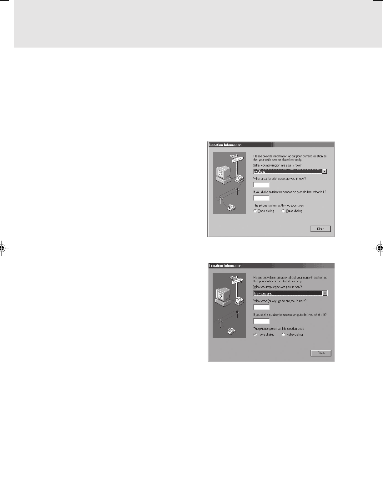
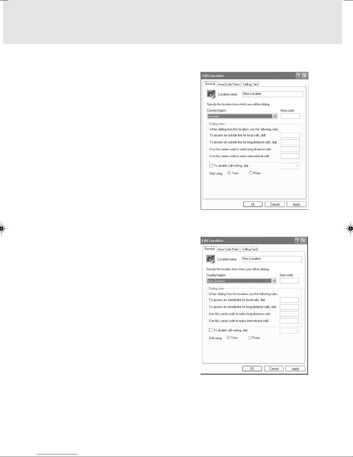
Note: Modem setting in Windows 98 / Windows Me
The default modem setting in Windows 98 / Windows Me operating system is United States of
America. If you are residing in Australia or New Zealand, please choose the appropriate country
where you are located.
The Modem will only operate with Tone Dialing; Selection of Pulse dialing is not possible.
Please see below instruction for quick modem setup.
A. If you are located in Australia
1. Go to Control panel, select modem icon.
2. Choose Australia in “What country/region
are you in now?”
3. Select Phone system as “Tone Dialing”
4. Close
B. If you are located in New Zealand
1. Go to Control panel, select modem icon.
2. Choose New Zealand in “What country/
region are you in now?”
3. Select Phone system as “Tone Dialing”
4. Close
vii
Page 8
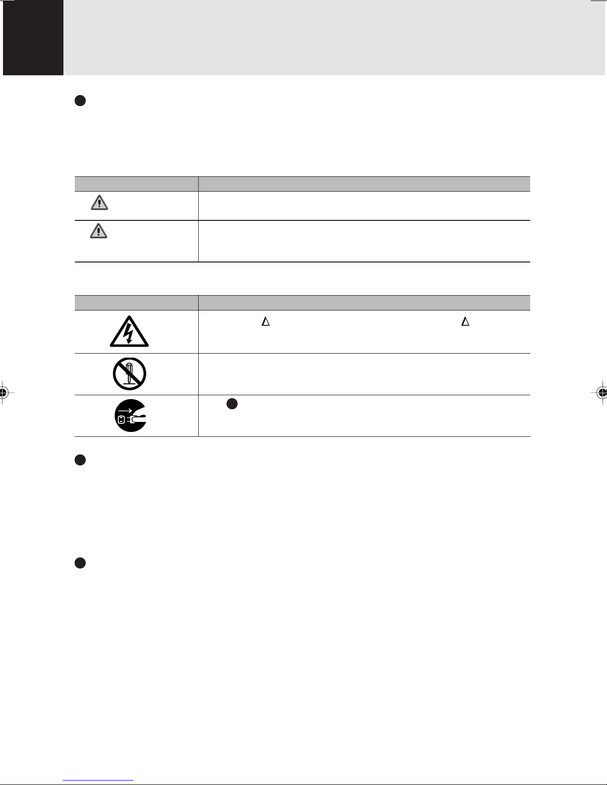
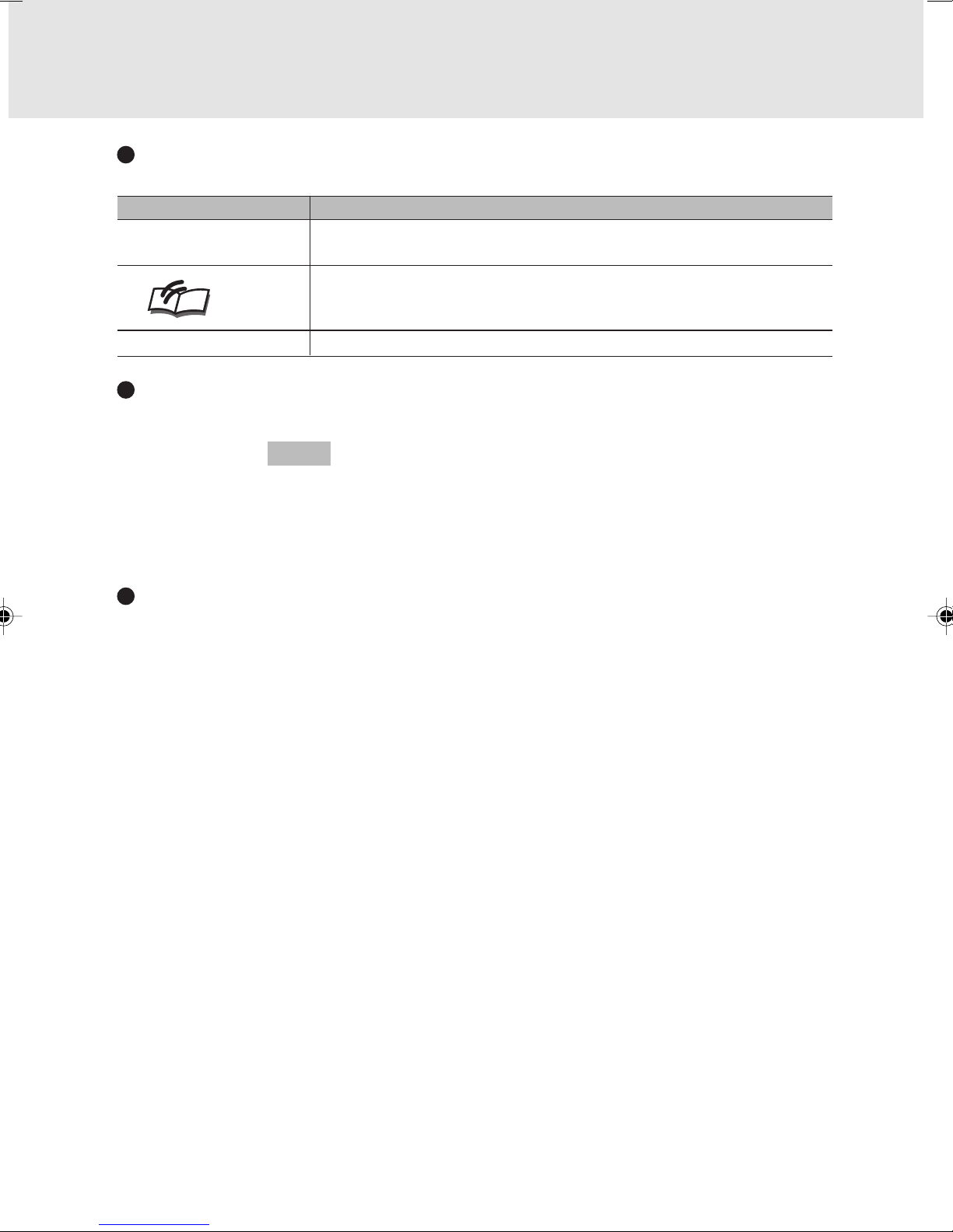
Note: Modem setting in Windows XP
A. If you are located in Australia
1. Click Start select Control panel select “Phone and
Modem Options”.
2. Double click New Location.
3. Choose “Australia” in Country/region pull down
menu bar.
4. Select Phone system as “Tone Dialing”.
5. Click OK and Apply.
B. If you are located in New Zealand
1. Click start select Control panel select “Phone and
Modem Options”.
2. Double click New Location.
3. Choose “New Zealand” in Country/region pull down
menu bar.
4. Select Phone system as “Tone Dialing”.
5. Click OK and Apply.
Note:
The screens and illustrations shown in this examples may slightly vary depending on the operating
environment that you have installed.
viii
Page 9
NOTATION IN THIS DOCUMENT
Warnings
This manual uses a variety of icons as visual marks so that you can use this computer safely
and correctly and avoid damage and danger to yourself and to others. These icons and their
meanings are as follows. Please learn these icons before reading this manual. Learning these
icons will be useful for understanding this manual.
Icon Meaning
WARNING
CAUTION
The symbols below are used together with the icons above to indicate what type of danger or
damage is involved.
symbols Meaning
Incorrect handling ignoring this warning can cause a dangerous situation
that could result in death or severe injury.
Incorrect handling ignoring this warning can cause a dangerous situation
that could result in moderate or minor injury or could result in equipment
damage.
The symbol indicates warning or caution. The symbol indicates the
concrete nature of the warning. (The example on the left is a
caution for electric shock.)
The circle and slash indicates prohibited behavior. The symbol inside
the circle indicates the concrete nature of the prohibition. (The example
on the left indicates that disassembly is prohibited.)
The indicates instructions that must be followed. The symbol inside
indicates the concrete nature of those instructions. (The example on
the left tells you to unplug the power plug from the socket.)
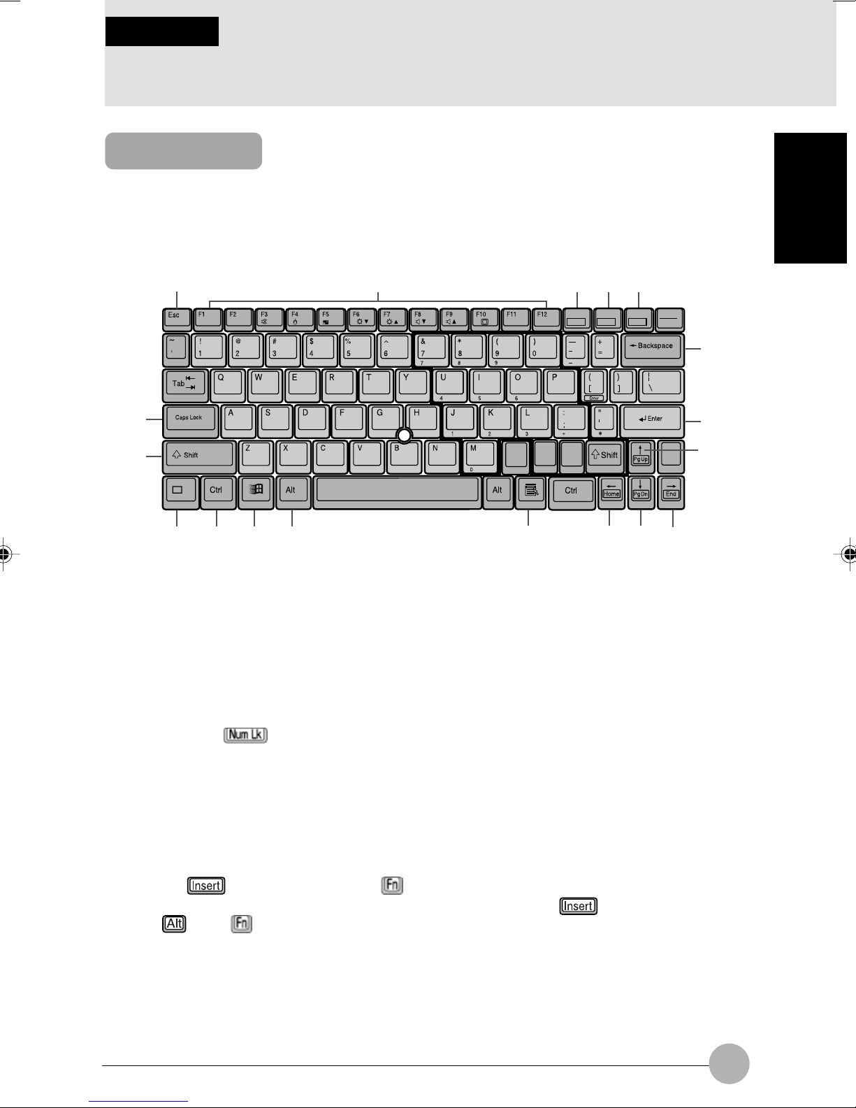
Key notation and operation methods
Explanations of key operations do not show all the characters on the keyboard. Instead they
indicate just the keys necessary to the explanation as follows.
Examples: [Ctrl] key, [Enter] key, [ → ] key
When multiple keys are to be pressed at the same time, this is indicated by connecting them
with [+].
Examples: [Ctrl] + [F3] keys; [Shift] + [ ↑ ] key
Screen examples
The screens shown in this manual are examples. Please understand that the file names and
screens you use may be different.
ix
Page 10
Notation in text
Here is what symbols in text mean.
Symbol Meaning
Critical Points
Critical Point Indicates a point necessary for correctly operating the
hardware or software.
Column Gives the meaning and brief explanation of a term.
Column
→ Indicates the page to see elsewhere in this manual.
Command input (key input)
Within the text of this manual, command input (giving commands to the computer by pressing
keys) is indicated as follows.
Example:
In the position indicated in the example above by the ↑, the space left between the characters
indicates that a space needs to be left in the entry by pressing the space bar (the long key with
nothing written on it at the center of the front of the keyboard). Commands are written in this
manual as lowercase latin letters, but uppercase letters may be used.
Product names
The following product names are abbreviated as follows in this manual.
dir c:
↑
“Microsoft® Windows XP® operating system” is written as “Windows XP”.
“Microsoft® Windows® 2000 operating system” is written as “Windows 2000”.
“Microsoft® Millennium® Edition operating system” is written as “Windows Me”.
“Microsoft® Windows® 98 operating system” is written as “Windows 98”.
“Windows NT 4.0” and “Windows NT 3.51” are both written as Windows NT.
“LifeBook” is written as “this computer” or “the computer main unit”.
x
Page 11

Configuration of this Manual
SECTION 1
This section explains basic operations and basic items for using this computer, including the
names of the parts and their functions, flat point operation methods, floppy disk unit handing,
and battery operation.
SECTION 2
This section explains installation of options for this computer.
SECTION 3
This section explains what to do when trouble occurs with this computer and when messages
are displayed. Read this section as the necessity arises.
SECTION 1
SECTION 2
SECTION 3
xi
Page 12

CONTENTS
SECTION 1
1 Names of the Parts and their Functions .......................... 2
2 Pointing Device ................................................................. 12
3 Keyboard ........................................................................... 15
4 Replacing the Internal Battery Pack ............................... 19
SECTION 2
1 Options .............................................................................. 22
Front features of the computer ......................................................... 2
Left/right features of the computer ................................................... 5
Rear features of the computer .......................................................... 8
Bottom features of the computer ...................................................... 9
Status indicator LCD ...................................................................... 10
About the Flat Point ........................................................................ 12
How to use the Flat Point ............................................................... 13
Keyboard ........................................................................................ 15
Options ........................................................................................... 22
Peripherals ..................................................................................... 23
2 Using a PC Card ............................................................... 24
Precautions for PC Cards ............................................................... 24
Installing a PC card ........................................................................ 26
Ejecting a PC card .......................................................................... 27
3 Using a CD/DVD ................................................................ 30
Loading a disc ................................................................................ 32
Ejecting the disc ............................................................................. 34
4 About Memory .................................................................. 37
5 Expanding Memory .......................................................... 42
6 Using a Mobile Multi-bay Unit ......................................... 46
7 Port Replicator .................................................................. 49
Installing the Port Replicator .......................................................... 49
Removing the Port Replicator ......................................................... 50
8 About the Integrated Wireless Lan
(For selected model) ........................................................ 51
Before Using This Device ............................................................... 51
Wireless Lan Modes ....................................................................... 51
Connecting Windows® 98/2000 Systems ........................ 52
Workflow ......................................................................................... 52
Setting Parameters ......................................................................... 52
xii
Network Connection: Windows 98 .................................. 55
Network Settings ............................................................................ 55
Network Connection: Windows 2000 .............................................. 59
Page 13

Sharing ........................................................................................... 61
Checking the Connection ............................................................... 63
Connecting Windows XP Systems.................................. 64
Workflow ......................................................................................... 64
Setting Parameters ......................................................................... 64
Network Connection ....................................................................... 65
Sharing ........................................................................................... 67
Checking the Connection ............................................................... 69
Troubleshooting ............................................................... 70
If a Second LAN Device is Installed................................ 76
About IP Addresses ......................................................... 77
Specifications ................................................................... 78
Glossary ............................................................................ 79
9 About the Internal Modem ............................................... 81
10 Using Internal LAN ........................................................... 83
Connecting a LAN cable ................................................................. 84
11 Connecting a USB Device ............................................... 86
Connecting a USB device............................................................... 87
SECTION 3
12 LifeBook Security/Application Panel .............................. 88
LifeBook Security / Application Panel ............................................. 88
Setting up your LifeBook Security Panel ........................................ 88
Passwords ...................................................................................... 89
Operating your LifeBook Security/Application Panel ...................... 90
Precautions .................................................................................... 91
Uninstalling the security Panel Application ..................................... 91
Configuring your LifeBook Application Panel ................................. 93
Configure your E-mail Account Settings ......................................... 96
Desktop Control Panel.................................................................. 101
13 Connecting a Mouse ...................................................... 103
Connecting a USB mouse ............................................................ 103
14 Printer .............................................................................. 105
Connecting Printer ........................................................................ 105
15 Connecting an External Display.................................... 107
Connecting an external display .................................................... 107
1 When This Happens ....................................................... 110
2 Care and Maintenance ................................................... 115
3 Glossary .......................................................................... 120
xiii
Page 14

SECTIONSECTION
SECTION
SECTIONSECTION
SECTIONSECTION
SECTION
SECTIONSECTION
11
1
11
11
1
11
SECTION 1
This section explains basic
operations and basic items for
using this computer, including the
names of the parts and their
functions, Flat point operation
methods, floppy disk unit handing,
and battery operation.
Page 15
SECTION 1
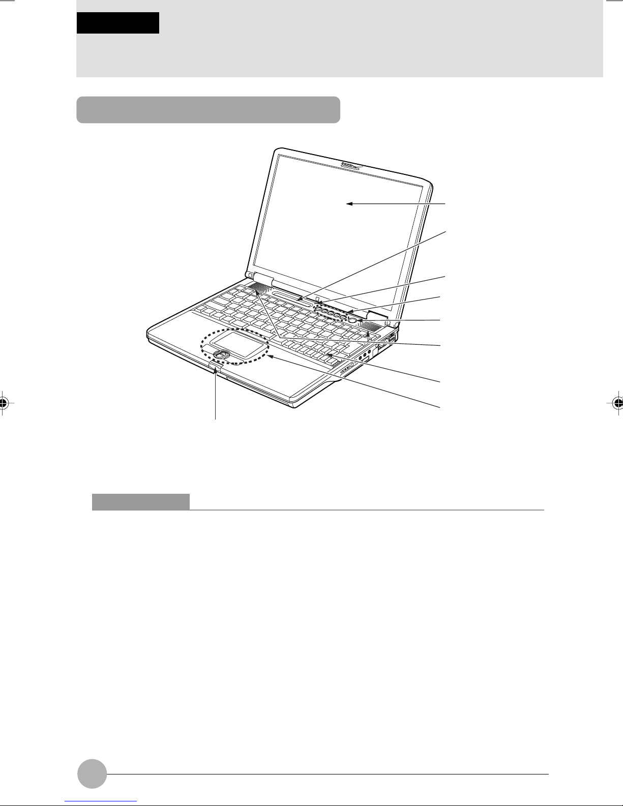
1 Names of the Parts and their Functions
Front features of the computer
1
2
3
4
9
1 LCD display
The monitor of your computer.
Critical Points
About the characteristics of LCD displays
For reasons of characteristics specific to LCD displays, the following phenomena may occur
but they are not defects in your LCD display.
• The TFT color liquid crystal display (LCD) of you computer consists of more than
2,350,000 pixels (dots) (if the resolution is 1024x768), which are arranged in rows and
columns through the utilization of high-level technology. For technical reasons, however,
some dots on your LCD display may not light up or be always lit, but this does not mean
that the display is defective.
• There may be a slight difference in color between your LCD display and another LCD
display because of differences in manufacturing condition. Moreover, your LCD display
may produce colors somewhat unevenly because of temperature changes, etc.
5
6
7
8
2 Status indicator LCD
Displays the operating status of the computer.
3 Built-in microphone
Used for sound recording.
2
Page 16

Critical Points
The microphone may cause a howling noise when you are using, for example, a karaoke
software program for which the microphone needs to be used along with the internal speakers.
If howling occurs, adjust the volume on your computer or use commercially available
headphones or an external microphone. When the microphone is not in use, you should cut
it off (mute).
The built-in microphone may not pick up all the sounds depending on the distance or direction
from the sound source. It is recommended that you use an external microphone if you want
to record sounds clearly.
4 One-touch buttons/Security panel
These buttons are used to set/reset security lock, password input during power on of the PC unit
and application start-up.
5 SUS/RES (Suspend/Resume) switch
Used to turn on your computer, to put it into standby (suspending operation) mode, or to resume
system operation.
6 Speakers
A sound output device of the computer
SECTION 1
7 Keyboard
Allows you to type in letters and give commands to the computer.
8 Flat Point
Used to move the mouse pointer on the screen. The scroll button at the center allows you to
scroll a window up or down.
Critical Points
For some applications, windows may not be scrolled using the scroll button.
9 Latch
This latch locks the liquid crystal display (LCD) to avoid accidental opening.
Press it to unlock and open the LCD.
3
Page 17
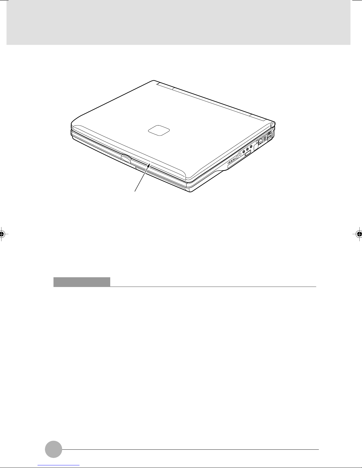
❑ Top of the PC Main Unit
1
1 Built-in wireless LAN antenna (for models with a wireless LAN module)
Your PC came with a built-in LAN antenna.
Note:
Wireless LAN ugradeability is only applicable to selected countries. Please contact your local sales
representative for more information.
Critical Points
When using your PC, especially when using the build-in wireless LAN module for
communication, take care not to touch the antenna. To avoid degradation in communication
quality, do not place your PC close to a conductor (substance that allows electricity to pass
along or through it).
4
Page 18

Left/right features of the computer
❑ Left panel of the computer
1
SECTION 1
23
1 Mobile multi-bay
Your computer came with a Combo Drive (DVD & CD-RW) or CD-RW drive built into this bay.
Depends which model you have.
Critical Points
To avoid damage to your computer, do not use the computer when the mobile multi-bay is
vacant.
2 Mobile multi-bay unit release lever
Raise the lever when removing the unit from the mobile multi-bay.
3 Antitheft lock port
Used to connect a commercially available antitheft cable.
Critical Points
The antitheft lock port supports the Kensington’s Micro Saver Security System.
When an anti-theft lock is connected, the mobile multi-bay unit cannot be removed.
5
Page 19
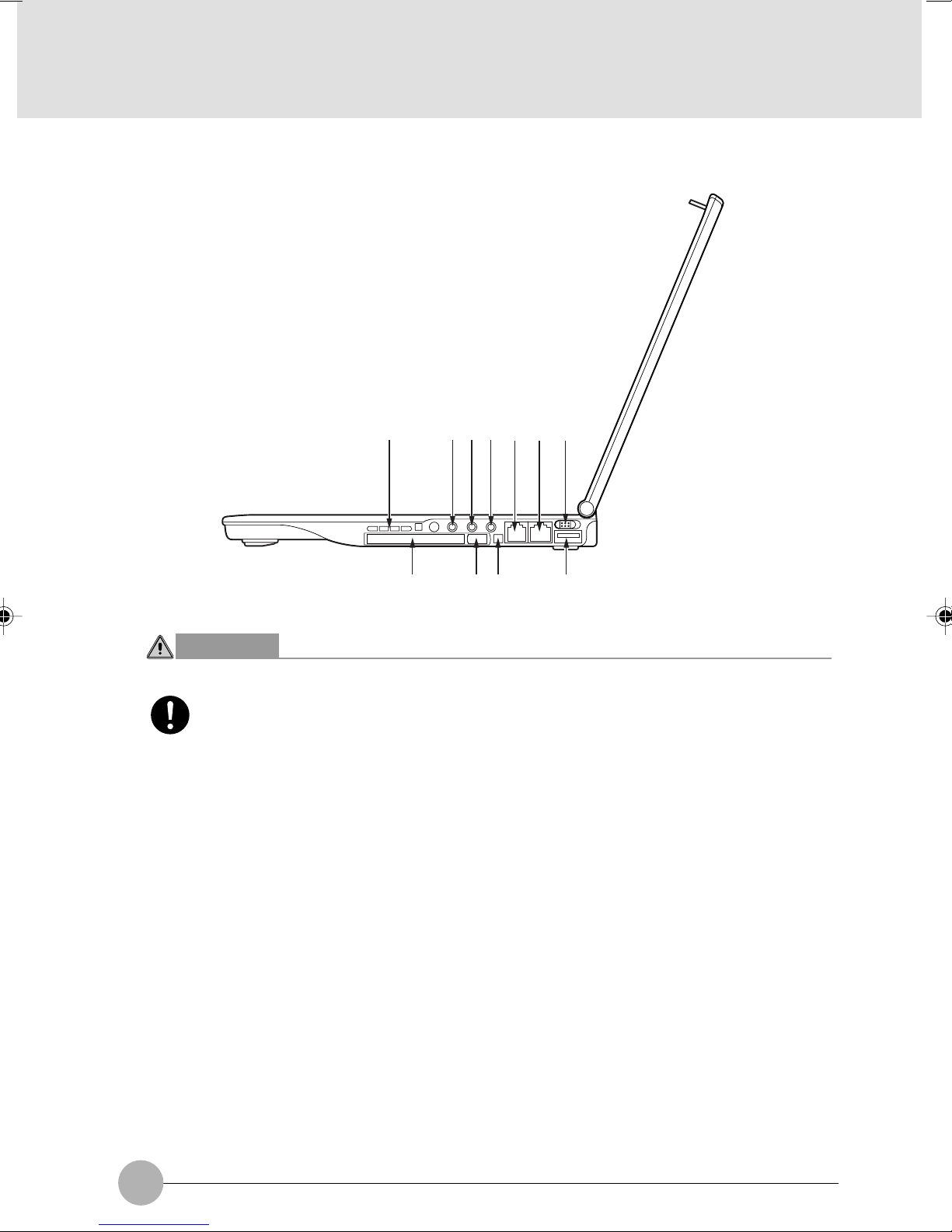
❑ Right panel of the computer
1
234 657
89 11
10
CAUTION
HEARING LOSS
• Before connecting a cable to the headphone jack, LINE IN jack, or microphone jack,
lower the volume on the computer to a minimum by pressing the [F8] key while
holding down the [Fn] key. Otherwise, the device connected could sustain damage
or a very loud noise could impair your hearing.
1 Air Vents
This is the air ventilation hole.
2 Microphone jack
Used to connect a commercially available monaural microphone (with a f3.5-mm mini plug) for
sound recording. Some types of microphones (e.g., dynamic microphones) cannot be used with
your computer. So before purchasing a microphone, make sure it is compatible with your computer.
3 LINE IN jack
This is an analog input (LINE IN) terminal used to connect the computer to the LINE OUT
terminal of an AV system (with a 3.5-mm stereo mini plug).
6
Page 20

4 Headphone jack
Used to connect commercially available headphones (with a f3.5-mm mini plug). Headphones
with some types of plugs cannot be connected. So before purchasing headphones, make sure
they are compatible with your computer.
CAUTION
HEARING LOSS
• Don’t raise the volume too high especially when you are listening with headphones.
Listening to very loud sound for a long time could impair your hearing.
HEARING LOSS
• Don’t turn on or off the computer while you are wearing headphones, or noise could
impair your hearing.
5 Modem port
This connector allows you to connect the computer to a telephone line and enables PC
communications and Internet connection through the modular cable.
6 LAN port
Used to connect the computer to a local-area network (LAN) via an optional LAN cable so that
you can use your computer on a network or connect to the Internet.
7 Main switch
Used to turn on your computer.
8 PC card slot
Used to install a PC card.
SECTION 1
Critical Points
Your computer came with a dummy card in the PC card slot.
9 PC card eject/lock button
Used to eject the PC card. This button also prevents the PC card from accidentally coming out of
the slot.
! IEEE 1394 (DV) port
Used to connect a peripheral device, e.g., a digital video camera (DV), to the computer via a DV cable.
" USB port
You can connect separately available USB standard peripherals such as a FDD unit or printer to
this port.
7
Page 21
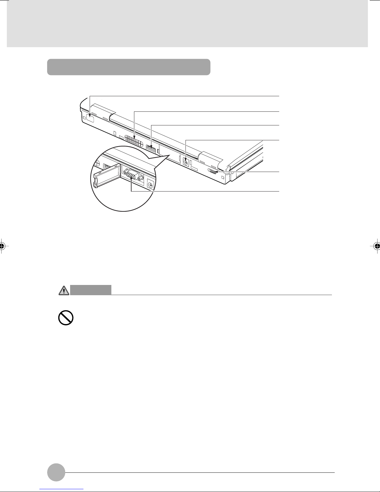
Rear features of the computer
1
2
3
4
5
6
1 Infrared Port
The fast IrDA compatible port allows you to communicate with another IrDA compatible infrared
device without a cable.
2 Air Vents
Used to discharge heat out of the computer. The cooling fan automatically starts rotating when
the temperature in the computer rises to a specific level.
CAUTION
FAILURE
• Do not block the air vent, otherwise the temperature in the computer will rise and
sometimes cause damage to the computer.
3 USB port
You can connect separately available USB standard peripherals such as a FDD unit or printer to
this port.
4 DC-IN connector
This is the connector to connect the AC adapter supplied to the computer.
5 Wireless switch
Turns on or off the communication feature using the wireless LAN module.
Slide the switch to the right to turn on the wireless LAN module, or to the left to turn it off.
Always keep the switch in the OFF position in a hospital, on an airplane or where the use of
electronic devices is restricted.
6 External display connector
Used to connect an optional external display, such as a CRT display.
8
Page 22
IMPORTANT
• When you connect peripheral devices to each corresponding connector, confirm the
correct direction of the connector and insert directly into the connector.
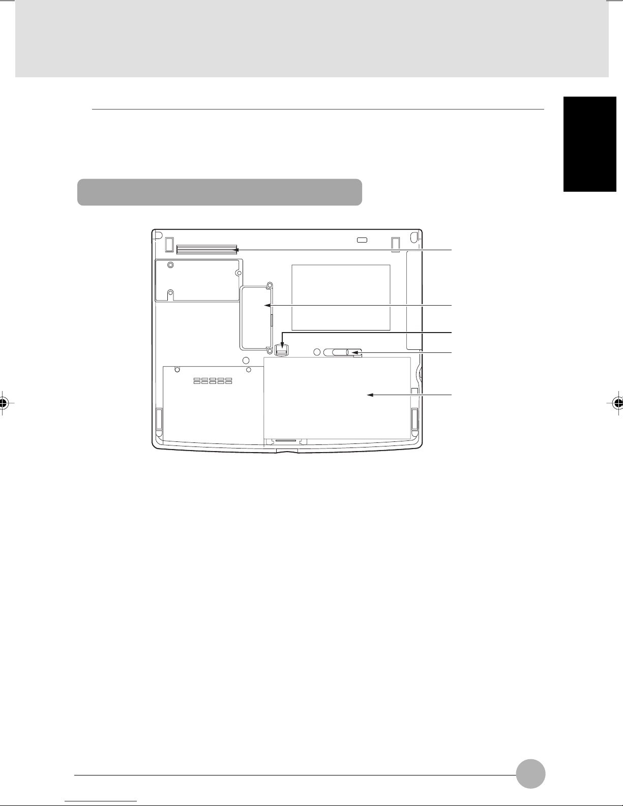
Bottom features of the computer
1
2
3
4
5
SECTION 1
1 Port Replicator Connector
This connector allows you to connect the Port Replicator to your notebook.
2 Expansion RAM (Random Access Memory) module slot
The memory module on your computer is installed here.
If needed, you can increase the amount of memory by replacing the memory module.
3 Release button
Slide this button to unlock the internal battery pack.
4 Internal battery pack lock
Slide this to install or remove the internal battery pack.
5 Internal battery pack
An internal battery pack is installed here.
9
Page 23
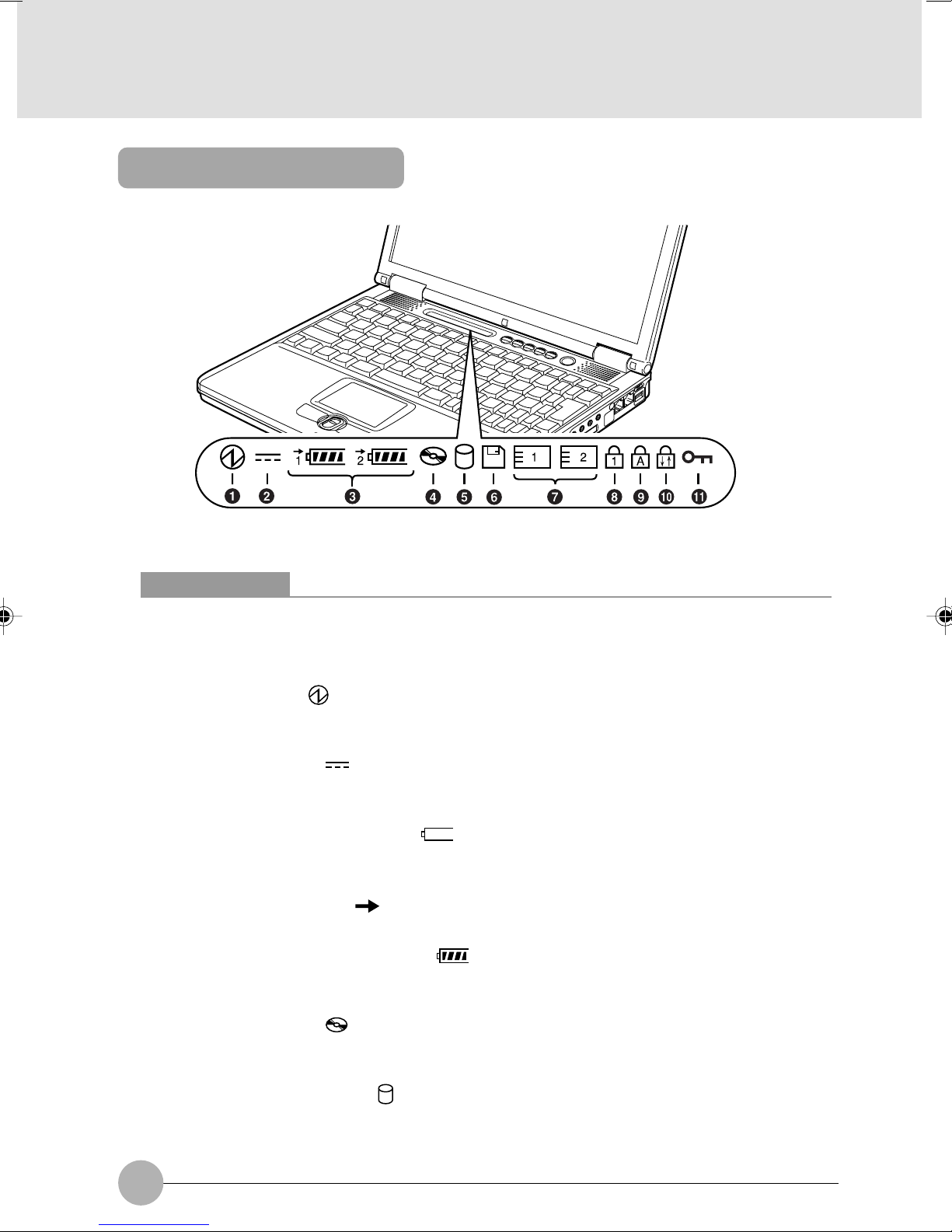
Status indicator LCD
Critical Points
No indicator is displayed on the status indicator LCD when the main switch is turned off,
except when the computer is being recharged.
1 SUS/RES Indicator ( )
This indicator comes on when the computer is running and blinks in standby status.
2 AC Adapter Indicator ( )
This indicator comes on when the power is supplied from the AC adapter.
3 Battery installation indicator ( 1, 2, )
This indicator appears when the battery is installed. The numbers 1 and 2 indicate the internal
battery and an optional add-on battery installed in the mobile multi-bay, respectively.
Battery Charge Indicator ( )
This indicator appears when the battery is charged.
Remaining Battery Power Indicator ( )
This indicator indicates the remaining battery power.
4 CD Access Indicator ( )
This indicator appears when a CD or DVD is accessed.
5 Hard Disk Access Indicator ( )
This indicator appears when the internal hard disk is accessed.
10
Page 24

Critical Points
If you turn off the main switch or operate the SUS/RES switch while the hard disk access
indicator is showing, the data on the hard disk may be corrupted.
6 Floppy Access Indicator ( )
The Floppy Drive Access indicator states whether the floppy disk drive is being accessed. This
indicator will flash if your software tries to access a disk.
7 PC Card Access Indicator (
This indicator appears when a PC card is accessed.
8 Num Lock (Numerical Lock) Indicator (
This indicator appears when the keyboard is set to ten-key mode. You can activate and deactivate
the ten-key mode by pressing the [ ] key.
9 Caps Lock Indicator (
This indicator appears when the keyboard is set for all capital letters. You can activate or deactivate
the Caps Lock mode by pressing [ ] key.
A
1
)
1
)
)
0 Scroll Lock Indicator ( )
This indicator appears when the scroll lock is activated to avoid screen scrolling. You can set and
reset the scroll lock by pressing the [ ] key while holding down the [ ] key.
The operation varies depending on the application when this indicator appears.
SECTION 1
" Security display ( )
When a password is set with the accompanying “Security Button”, this lights up when the password
is required. If the security display lights up when this computer’s power is switched On or when
it resumes operation, input the password.
11
Page 25
SECTION 1
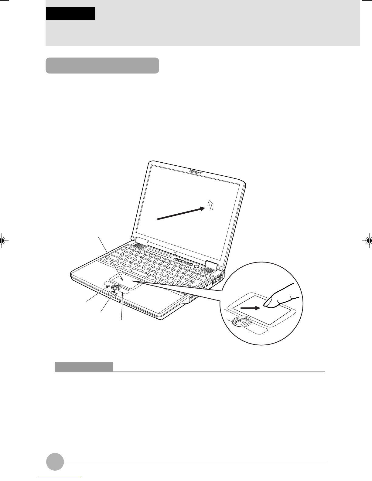
2 Pointing Device
About the Flat Point
The Flat Point is a handy pointing device that enables you to move the mouse pointer freely with
your finger. It consists of a touch-pad, left and right buttons on this side of the touch-pad, and the
scroll button between the left and right buttons.
The touch-pad has the same function as the ball in a mouse. You can move the mouse pointer in any
directions on the screen by sliding the tip of a finger on the touch-pad. Moreover, if you tap the touchpad with a finger, you can click, double-click, point to, or drag any object on the screen.
The left and right buttons correspond to the left and right buttons of a mouse, and their functions
vary from application to application.
Pressing the scroll button forward or backward enables you to easily scroll a window up or down.
Touch-pad
Left button
Scroll button
Right button
Critical Points
The Flat Point may malfunction if condensation occurs or if it is moistened. In addition, if you
operate it with a moistened or sweaty finger, or if the Flat Point surface is dirty, the mouse
pointer may not move correctly. In such a case, turn off your computer and wipe dirt off with
a soft cloth slightly dampened with dilute detergent.
Some applications do not allow you to use the scroll button to scroll windows.
You can use an optionally available USB mouse instead of the Flat Point.
12
Page 26
How to use the Flat Point
• Click
or
• Double-click
or
• Point
“Click” means quickly pressing the left button once or
tapping the touch-pad once.
Pressing the right button once is called “right-click.”
“Double-click” means pressing the left button twice in a
row or tapping the touch-pad twice in a row.
“Point to an item” means moving the mouse pointer onto
a menu item, and so on, to select it. Pointing to an item
highlights it and displays an explanation about it. If the
item to which you pointed has a submenu (such items
are marked with ), the submenu appears.
SECTION 1
• Drag
• Scroll
or
To return, push
this forward.
To advance, push
this backward.
To drag an object, move the mouse pointer onto the
object, move the object to the desired location by sliding
the finger on the touch-pad while holding the left button
down, and then move the finger off the pad. Or, move
the mouse pointer onto the object, and tap the touchpad twice in a row. After that, without moving the finger
off the pad, slide it to move the object to the desired
location, and then move the finger off the pad.
To scroll a window, click anywhere in the window and
push the scroll button forward or backward to scroll the
window.
13
Page 27

Critical Points
You can change the functions assigned to the right and left buttons and also adjust the
mouse speed, using the Mouse Properties dialog box. To display this dialog box, click the
Printers and other hardware icon in the Control Panel window and select Mouse.
When tapping the touch-pad, tap it quickly with the tip of a finger but not strongly.
The mouse pointer moves in the same direction as you slide a finger on the touch-pad. If the
finger reaches one edge of the pad before you move the pointer to the desired location,
move the finger off the pad temporarily, put it in an adequate place on the pad and start
sliding the finger again.
❑ Using the scrolling function
The scroll button enables you to easily scroll a window.
1 Click any place in the area (of the window) that you want to scroll.
(The illustration varies depending on the model and use conditions.)
2 Move the scroll button forward and backward.
The window scrolls in the same direction you moves the button.
To return, push this forward.
To advance, push
this backward.
14
Page 28
SECTION 1
3 Keyboard
Keyboard
❑ Names and functions of the principal keys
Keys that can be used as ten-keys
2
6
7
Fn
!
# $ % ^&*
@
1 Esc (Escape) key
Used to cancel the current task and return to the previous task.
SECTION 1
5
4
31
Delete
SysRq
Pause
Break
8
9
!
Insert
Num Lk
Prt Sc
Scr Lk
>
<
,
?
.
/
.
/
2 Function keys
Functions assigned to these keys vary from application to application.
3 Num Lk (Numerical Lock) key
Pressing the [ ] key activates the ten-key mode. To deactivate the ten-key mode, press it
once again.
4 Insert / Prt Sc (Print Screen) key
• Insert key
Used to specify whether to overwrite an existing string or to insert a new string.
• Prt Sc (Print Screen) key
Used to save the currently displayed windows as pictorial data (bitmap file). To do so, press
the [ ] key while holding the [ ] key down.
To save only the active window as pictorial data, press the [ ] key while holding the
[ ] and [ ] keys down.
Using painting software (e.g., Paint), you can edit, save, and print pictorial data. To do so,
you need to import it to the painting software by selecting the Paste command from the Edit
menu.
15
Page 29
5 Delete key
Used to delete the character on the right of the cursor. With this key, you can also delete the file
or icon you selected.
By pressing the [ ] key while holding the [ ] and [ ] keys down, you can forcibly
terminate the out-of-control application or computer.
6 Caps Lock key
To fix to the English Capital mode, press the [ ] key.
To deactivate the English Capital mode, press these key again.
7 Shift key
Used in combination with other keys. By pressing a key while holding the [Shift] key down, you
can enter the character or symbol printed in the upper case of the key.
8 Back Space key
Used to delete the character on the left of the cursor.
9 Enter key
Used to confirm the string entered.
In text processing, pressing this key inserts a hard return in the text. That’s why this key is also
called the Return key.
0 Pg Up (Page Up) key/Cursor keys
Used to return to the previous page. To do so, press the [ ] key while holding the [ ] key
down.
Used to move the cursor upward, downward, to right and left.
16
Page 30

! FUNCTION KEYS
Your LifeBook notebook has 12 function keys, F1 through F12. The functions assigned to these
keys differ for each application.
The [FN] key provides extended functions for the notebook and is always used in conjunction
with another key.
• [FN+F3]: Pressing [F3] while holding [FN] will toggle the Audio Mute on and off.
• [Fn+F4]: Pressing [F4] while holding [Fn] will toggle the Quick Point feature on and off. Note
that the [Fn+F4] combination only works if Manual Setting is selected in the BIOS.
• [FN+F6]: Pressing [F6] repeatedly while holding [FN] will lower the brightness of your display.*
• [FN+F7]: Pressing [F7] repeatedly while holding [FN] will increase the brightness of the
display.*
• [FN+F8]: Pressing [F8] repeatedly while holding [FN] will decrease the volume of your LifeBook
note-book.**
• [FN+F9]: Pressing [F9] repeatedly while holding [FN] will increase the volume of your LifeBook
notebook.**
• [FN+F10]: Pressing [F10] while holding [FN] allows you to change your selection of where to
send your display video. Each time you press the combination of keys you will step to the
next choice. The choices, in order, are: built-in display panel only, both built-in display panel
and external monitor or external monitor only.
* There are eight brightness levels.
** There are 17 audio levels.
SECTION 1
@ Ctrl key
Used in combination with other keys.
# Windows key
Used to open the Start menu.
$ Alt key
Used in combination with other keys.
% Application key
Used to open the pop-up menu for the item selected.
This key has the same function as the right button of the Flat Point.
^ Home key/Cursor keys
Used to move the cursor to the beginning of the line on which it is currently placed. To do so,
press the [ ] key while holding the [ ] key down. Pressing the [ ] key while holding the
[ ] and [ ] keys down causes the cursor to move to the beginning of the text.
& Pg Dn (Page Down) key/Cursor keys
Used to display the next page. To do so, press the [ ] key while holding the [ ] key down.
Used to move the cursor upward, downward, to right and left.
17
Page 31

* End key/Cursor keys
Used to move the cursor to the end of the line on which it is currently placed. To do so, press the
[ ] key while holding the [ ] key down. Pressing the [ ] key while holding the [ ] and
[ ] keys down causes the cursor to move to the end of the text.
Used to move the cursor upward, downward, to right and left.
❑ About the ten-key mode
The ten-key mode refers to the mode that enables you to use certain character entry keys as tenkeys (a key arrangement that makes it easy to type in figures). To activate the ten-key mode, simply
press the [ ] key. In the ten-key mode, 1 is displayed on the status indicator LCD. The figure
you can enter with a ten-key is marked on the front surface of the key. Note that connecting an
optional ten-key pad disables the ten keys on your computer.
18
Page 32

SECTION 1
4 Replacing the Internal Battery Pack
WARNING
ELECTRIC SHOCK
• Before replacing the battery pack, be sure to turn off the computer and disconnect
the AC adapter from it. Also, don’t touch any connector of the computer or battery
pack to avoid electric shock or malfunction.
❑ Replacing the internal battery pack
1 Turn off the power to the computer and disconnect the AC adapter.
2 Close the LCD display and turn the bottom side of the computer up.
3 Release the lock.
(1) Slide the internal battery pack lock while sliding the release button in the direction of the
arrow, and (2) release the lock.
SECTION 1
Release button
Internal battery pack lock
1
2
19
Page 33

4 Remove the internal battery pack.
Put a finger in the indentation opened as a result of sliding the internal battery pack lock, and lift
the internal battery pack.
Internal battery pack lock
Indentation
Internal battery pack
5 Install a new battery pack.
Insert the new battery pack diagonally into the bay and push it down until it is set in place.
6 Slide the internal battery pack lock until it clicks into place.
(1) Slide the internal battery pack lock to the right end, and (2) make sure that the red-colored
part of the release button is completely hidden.
Internal battery pack lock
Red-colored part
2
20
1
Page 34

SECTIONSECTION
SECTION
SECTIONSECTION
SECTIONSECTION
SECTION
SECTIONSECTION
22
2
22
22
2
22
This section explains installation
of options for this computer.
SECTION 2
Page 35

SECTION 2
1 Options
Options
You can expand the functions of this computer by connecting various options.
Printer
Combo drive unit
(DVD/CD-R/RW)
CD-R/RW drive
unit
External
display
Numerical keypad
Mouse
FDD unit
(USB)
Memory
USB mouse
PC card
Battery
Super disk drive
unit (Optional)
PC Card Slot unit
(Optional)
2nd Battery
(Optional)
Weight Saver unit
(Optional)
22
USB devices: Supported by Windows XP, Windows
2000, Windows 98 and Windows Me
only
Page 36

Peripherals
Below explanation is necessary for your knowledge before connecting your peripherals.
Some setting up works are required for a certain peripherals
You cannot use some PC peripherals just by connecting it to a PC. Those peripherals require
some setting up work after connection. For example, printers and PC cards require “driver
installation” work after connecting them. And memory and other peripherals do not require such
setting up works. Make sure to consult with this document for the peripheral connection to
complete the work correctly.
See also the documents for the peripherals
The peripheral installation methods shown in this document are only a few examples. Make
sure to consult with the documents for the peripherals as well as this document.
Use genuine products
Use genuine optional device from our company. We cannot guarantee proper function on this
PC for the peripherals from other sources. When it is necessary to use the peripheral from the
other source, consult with the manufacturer of the product.
Use the peripherals that conform to ACPI standard
This PC is set to ACPI mode for Windows XP, Windows 2000 and Windows 98. Power save and
other functions may not work correctly if a peripheral does not conform to ACPI mode.
SECTION 2
Notes on installation/removal
The installation of the peripheral must be done after the setting up of an operating system
except for a PS/2 mouse. The set-up function might not complete correctly if such a peripheral is
attached before the operating system set up.
Critical Points
When you connect a peripheral to a connector, make sure that the direction of the connection
is correct and connect straight.
When you connect more than one peripherals, complete setting for each peripherals before
installing others.
23
Page 37

SECTION 2
2 Using a PC Card
Precautions for PC Cards
Observe the following points when using PC cards to prevent breakdown.
Do not place PC cards in hightemperature locations and
locations subject to direct
sunlight.
Do not place heavy objects on
top of PC cards.
Do not subject PC cards to
strong shocks.
Be careful to avoid spilling coffee
and other liquids on PC cards.
Avoid rubbing PC cards and
building up static electricity.
When storing a PC card, always
place it in its special case.
24
Page 38

❑ Caution in using PC cards
CAUTION
FAILURE
• A PC card is composed of parts very sensitive to static electricity, and it may be
damaged even by static built up in a human body. Before handling a PC card, always
touch a metal object with your hand to discharge static.
You should pay attention to the following points when you use PC cards in order to prevent
failure
• Avoid exposing PC cards to direct sunlight or high temperature.
• Avoid subjecting PC cards to shocks.
• Do not place heavy objects on top of them.
• Avoid getting PC cards wet.
• Store PC cards in their cases when not in use.
❑ PC cards that can be used with your computer
Your computer is compatible with PC Card Standard-compliant Type I PC cards and Type II PC
cards. Here are some examples of these types of cards.
SECTION 2
• Adapter card
This PC card is needed to load pictorial data from a smart media for digital cameras into
the computer.
• SCSI Card
This PC card is needed to connect a SCSI device, such as a SCSI hard disk or MO
(Magneto-Optical) drive.
Critical Points
Your computer does not support PC cards with a working voltage of 12V.
❑ Preparing necessary items
PC card
PC card driver
Manual of the PC card
Prepare a PC card that meets your need.
A CD or floppy disk that contains the PC card driver is supplied with
some PC cards.
Setting procedures vary depending on the PC card used. So be
sure to read also the manual of your PC card.
25
Page 39

Installing a PC card
CAUTION
INJURY
• Do not put your finger into the PC card slot when you install a PC card, or you may
be injured.
Critical Points
It may be required to turn off the power to the computer or to install a device driver when you
install a specific PC card. Check with the manual supplied with each PC card.
1 Eject the dummy card from the PC card slot.
Raise and press the PC card eject/lock button to eject the dummy card.
PC card eject/lock button
Dummy card
2 Install a PC card.
Insert the PC card into the PC card slot as far as it will go, with the labeled face facing upward.
PC card
26
Page 40

3 Lock the PC card.
Fully pull out the PC card eject/lock button, collapse it backward, and lock the PC card with the
fitting.
PC card eject/lock button
4 If the PC card is being installed for the first time, install any necessary driver.
Some PC cards require the installation of a driver. Check the manual supplied with each PC
card and install a driver if required.
A floppy disk or a CD may be required to install a driver.
5 Click the icon (Safely Remove Hardware) in the lower right corner of the screen
(notification area where a clock is displayed), and make sure that the name of the PC card
inserted is displayed correctly.
- If the name of the PC card is displayed, click any vacant area on the desktop. in the “Ejecting
a PC card” section, and insert the PC card again.
SECTION 2
Critical Points
When you use a PC card attached with a cable, do not put anything heavy on, or apply a
shock to, the connector of the cable connected with the PC card, or it may damage the
equipment.
Ejecting a PC card
Critical Points
When you remove a PC card attached with a cable, do not pull the cable connected to the
PC card or it will result in failure.
When you remove a PC card, follow the procedure below or it will result in failure.
Some PC cards require shutting down when you remove them. Consult with the manual of
the PC card.
27
Page 41

CAUTION
HIGH TEMPERATURE
• A PC card may be quite hot right after use. Wait for a while before removing a PC
card after Step 3, to avoid burning your fingertips.
INJURY
• When you remove a PC card, do not insert your finger into the PC card slot to avoid
cutting your fingertips.
1 Click the icon (Safely Remove Hardware) in the lower right corner of the screen
(notification area where a clock is displayed).
Critical Points
Don’t eject the PC card by clicking the Stop button in the Safely Remove Hardware dialog
box that appears when you double-click the icon (Safely Remove Hardware) in the
lower right corner of the screen (notification area where a clock is displayed). Doing so may
cause your computer to become unstable.
2 If the PC card is being installed for the first time, install any necessary driver.
XXXXXXXX refers to the name of the PC card inserted.
3 When the message “Remove Hardware” appears, raise the PC card eject/lock button.
PC card eject/lock button
28
Page 42

4 Eject the PC card.
Press the PC card eject/lock button to eject the PC card.
PC card eject/lock button
PC card
5 Install the dummy card.
Insert the dummy card into the PC card slot as far as it will go, fully pull out the PC card eject/
lock button, and collapse it backward to lock the dummy card.
PC card eject/lock button
Dummy card
SECTION 2
29
Page 43

SECTION 2
3 Using a CD/DVD
In this manual, CD-ROMs, music CDs and CD-R/RW discs are collectively referred to as CDs,
and DVD-ROMs and DVD-VIDEOs are referred to as DVDs.
CAUTION
INJURY
• When inserting or ejecting a CD or DVD, don’t put any fingers on the disc tray to
prevent possible injury to them.
❑ Caution in handling a CD/DVD
Keep the following in mind when using a CD/DVD.
• When you unscrew the screws on your PC, use the cross-point screwdriver with the
appropriate size for the screws. Using screwdrivers other than that may damage the head of
screws.
• When taking out a disc from the case or loading it in your computer, don’t touch any surface
of it.
• Handle a disc with care so as not to put fingerprints on it, to make it dirty or dusty, or to
scratch it, otherwise no data could be read from it, written or rewritten on it. Soiled audio
CDs or DVD-VIDEOs may not be played back normally.
• Don’t stick any label on any surface of a disc, or write anything to it with a ball-point pen or
pencil.
• Be careful not to spill coffee or any other liquid over a disc.
• When a disc is dirty or condensation occurs on it, wipe the disc radially from the center with
a slightly moistened cloth, then with a dry cloth. Don’t use a hairdryer to dry it or don’t let a
wet disc dry naturally.
• Don’t use benzene, thinner, water, record cleaner, antistatic spray, or silicone cloth to clean
discs.
• Always keep discs in their cases when they are not in use.
• Don’t bend a disc or put any heavy object on top of it.
• Don’t store discs in an extremely hot or cold place.
Reading (playback)*1
Writing
Rewriting
*1: Note that some types of discs cannot be used with your computer or application software may be required
to play them.
*2: DVD-ROMs refer to DVDs containing information, including programs with which you can see the data on
computer displays.
DVD-VIDEOs refer to DVDs on which sound and pictorial data are recorded.
DVD-RAM, DVD-RW, DVD+RW, or DVD-Audio discs cannot be used with your computer.
30
CD-ROM,
audio CD,
video CD,
photo CD
O
X
X
CD-R
O
O
X
CD-RW
O
O
O
DVD-ROM,
DVD-VIDEO
*2
O
X
X
Page 44

When you purchase CD-R/RW discs be sure check whether they meet the data writing and rewriting
speeds of your drive.
Critical Points
Don’t use CDs or DVDs other than round discs (e.g., deformed discs, including star-shaped
discs and card-type discs).
Data cannot be read/written correctly from/on a deformed disc or a deformed disc could
cause the CD/DVD drive to fail.
The region code of your computer’s DVD drive is 3. DVD-VIDEOs with a country-specific
region code may not be used with your drive if their region codes don’t agree with that of
your drive.
Some DVD discs are copy-protected for copyright protection. Your computer has Descramble
and Authentication features to prevent unauthorized duplication of DVDs, so that if data
protected by copyright is copied, it cannot be played because of an authentication error.
SECTION 2
31
Page 45

Loading a disc
IMPORTANT
• You should preferably power the computer from the AC adapter when frequently accessing
a CD or playing back a DVD-VIDEO.
• To set a disc on the disc tray, align the center of the disc with the projection at the center
of the tray and push the disc down until it clicks into place.
Otherwise it may come off in the drive, causing damage to the disc tray and drive or the
disc itself.
• When you are using a disc that starts automatically when it is loaded, don’t put your
computer into standby mode. If you place the computer into standby (suspending
operation) mode while using an auto-run CD, the CD will start twice when you resume
system operation (when you restore the operation at the point at which you suspended
operation), and this could cause the computer to malfunction. If you let the CD start
twice, exit all programs on the CD, and load it over again.
• When data is being read, the CD/DVD runs at very high speeds and sometimes causes
vibration and hiss noise.
1 Press the CD eject button.
The disc tray pops out a little.
CD eject button
2 Pull out the tray gently.
2
1
32
Page 46

Critical Points
If the tray does not come out
- If you have already shut down Windows, turn your computer back on and press the CD
eject button.
If the main switch is in the Off position ( ), slide it to the | position to turn on the computer,
and then press the CD eject button.
You may press the CD eject button even when the icon is blinking on the status indicator
LCD.
3 Set a disc on the tray while holding the tray.
Align the hole of the disc with the projection at the center of the tray with the labeled surface up,
and push the disc down until it clicks into place. Failure to fit a disc correctly onto the projection
could prevent the disc from being ejected.
Disc tray
SECTION 2
Projection
4 Push the tray gently into the computer.
It takes about 10 seconds for your computer to get ready to start the loaded disc.
33
Page 47

Critical Points
If a message appears, asking you what to do “If a disc containing this kind of file is inserted
...,” click “No, ...” and click OK.
When you load a multi-session CD, it may take much time for your computer to get ready to
start.
If you insert an audio CD in your computer while Windows is running, CD Player application
starts automatically to play it. You can use the one-touch buttons or CD Player to perform the
following operation.
Ejecting the disc
1 Exit the application you started from the disc.
2 Press the CD eject button.
The tray pops out a little.
34
CD eject button
Page 48

3 Pull out the tray gently.
Disc tray
2
1
Critical Points
If the tray does not come out
- If you have already shut down Windows, turn your computer back on and press the CD
eject button.
- If the main switch is in the Off position ( ), slide it to the | position to turn on the
computer, and then press the CD eject button.
You may press the CD eject button even when the icon is blinking on the status indicator
LCD.
SECTION 2
4 Take out the disc while holding the tray with a hand.
To detach the disc, lift the edge of the disc while holding the projection with a finger.
Disc tray
Projection
35
Page 49

5 Push the tray gently into the computer.
Critical Points
If the disc won’t come out:
1. Click the Start button, and select My Computer.
2. Move the mouse pointer onto the CD Drive icon in the My Computer window.
3. Press the right button once on the Flat Point.
4. Click Eject.
The tray pops out a little.
5. Pull out the tray gently and take out the disc from it.
If you cannot eject the disc by this method, follow these steps.
1. Turn off your computer.
2. Insert a straightened paper clip, etc., into the pinhole on the right of the CD eject button.
The tray will pop out a little.
3. Pull out the tray gently and take out the disc from it.
CD eject button
36
Page 50

SECTION 2
4 About Memory
❑ Installing/removing memory
This section explains how to install/remove memory in or from your PC.
WARNING
ELECTRIC SHOCK
• To avoid shock hazards, always turn off your PC and detach the AC adopter from it
before installing/removing memory.
SWALLOWING
• To avoid danger of suffocation, keep detached small parts, such as covers, caps or
screws, away from babies and children.
If a child has swallowed any of these parts, consult the doctor immediately.
CAUTION
SECTION 2
FAILURE
• When installing or removing memory, catch hold of its edge to avoid touching the
terminal or IC. Be careful not to touch internal parts or terminals to avoid poor contact.
FAILURE
• Memory is composed of static-sensitive parts and it is broken easily if static electricity
build in a human body is discharged and flows through it. To avoid damage to the
memory, be sure to touch a metal object to discharge static electricity before touching
the memory.
FAILURE
• Before installing or removing memory, always turn off your PC. Installing or removing
memory with Windows XP/2000/Me/98 on standby or your PC in the Hibernation
mode could result in the loss of data or cause damage to your PC or memory.
IMPORTANT
• To remove screws from your PC, use a – 1 screwdriver that matches the size of the
screws (M2). The use of a screwdriver of any other size could cause damage to the
head of a screw.
• Do not install any memory other than Fujitsu tested memory.
37
Page 51

Critical Points
To check the memory size, open the Information menu of BIOS Setup Utility and select
Memory Slot from it. The size of the memory installed on your PC is displayed like this:
“64MB SDRAM.” If your PC does not start although memory is installed correctly, the memory
can be faulty or defective. In that case, contact Fujitsu Personal Echo Center or your local
retailer.
To avoid damage to your PC, do not touch any internal parts other than those you need to
touch for the installation or removal of memory.
To avoid damage to your PC, take care not to drop detached screws, and so on into the PC.
To upgrade the memory on your PC, for example to 1 GB, you will need to remove the
existing RAM module or modules.
❑ Installing memory
1 Turn off your PC and disconnect the AC adopter from it.
2 Close the LCD panel and place your computer upside down.
3 Remove two screws and detach the expanded RAM module slot cover.
Detach the expanded RAM module slot cover on the bottom of the PC.
Expanded RAM
module slot cover
4 Install a new RAM module.
Align the notch in the RAM module with the protrusion in the slot, and insert it diagonally into the
slot until it clicks into place.
Your PC is provided with two expanded RAM module slots: upper slot (DIMM 2) and lower slot
(DIMM 1).
Notch in the
RAM module
Upper slot (DIMM2)
38
Lower slot (DIMM1)
Page 52

5 Attach the expanded RAM module slot cover and secure it with screws.
Reattach the cover removed in Step 3.
Expanded RAM
module slot cover
IMPORTANT
• If memory is not installed properly, the message “Expanded Memory Error” will be
displayed in English or nothing will be displayed on the screen when you first turn on
your PC after installing the memory. If this happens, turn off the main switch of your PC,
and remove and reinstall the memory correctly.
❑ Removing memory
1 Turn off your PC and disconnect the AC adopter from it.
2 Close the LCD panel and place your PC upside down.
3 Remove two screws and detach the expanded RAM module slot cover.
Detach the expanded RAM module slot cover on the bottom of the PC.
Expanded RAM
module slot cover
SECTION 2
4 Remove the memory.
Detach the RAM module from the slot while opening in opposite directions both tabs fastening
the RAM module, as shown in the figure below.
Tab (upper slot)
Expanded RAM module slot (DIMM2)
Tab (lower slot)
39
Page 53

5 Attach the expanded RAM module slot cover and secure it with screws.
Reattach the cover removed in Step 3.
Expanded RAM
module slot cover
Critical Points
To replace the memory in the lower slot, follow these steps.
1. Open the tabs on both sides of the lower slot in opposite directions, as shown in the
figure below. This causes the memory to come up slightly.
Tab (upper slot)
Tab (lower slot)
2. Similarly, open the tabs on both sides of the upper slot. This causes the memory to
come up further.
Detaching the memory forcibly without releasing the tabs on both sides of the upper slot
could damage the tabs. To avoid this, be sure to release them when removing the memory.
3. Detach the memory.
Pull the memory diagonally upward to detach it from the lower slot.
40
Expanded RAM module slot (DIMM1)
Page 54

4. Install a new RAM module in the lower slot.
Align the notch in the RAM module with the protrusion in the lower slot, and insert it
diagonally into the slot until it clicks into place.
Notch in the
RAM module
Check to see that the memory is fastened securely by the tabs on both sides. If a tab is
in a state shown below, the memory is not mounted correctly.
SECTION 2
In this case, further push the memory into the slot.
41
Page 55

SECTION 2
5 Expanding Memory
❑ Preparing necessary items
Memory (Expanded RAM
module)
Philips screwdriver
(Size: #1)
❑ Replacing memory
WARNING
ELECTRIC SHOCK
• Before replacing memory, always turn off your computer and disconnect the AC
adapter from it, or you could get an electric shock.
SWALLOWING
• The cover, cap, screw, etc., removed could choke babies and children if they are
swallowed accidentally. To avoid danger of suffocation, always keep them out of the
reach of babies and children.
In the event any of these items is swallowed, consult a doctor immediately.
You can additionally install memory.
Used to remove the screw securing the cover. Use a Philips
screwdriver that meets the size of the screw (M2.0). Using a
screwdriver of other size may cause damage to the screw head.
42
Page 56

CAUTION
FAILURE
• When replacing memory, don’t touch its terminals or ICs but hold its edges. Also, be
careful not to touch any components or terminals inside the computer. Touching a
terminal with oily fingers could cause poor contact.
FAILURE
• Memory is composed of parts very sensitive to static electricity, and it may be
damaged even by static built up in a human body. Before handling memory, always
touch a metal object with your hand to discharge static.
FAILURE
• Before replacing memory, be sure to turn off the computer. Replacing while the
computer is in standby or hibernation mode could cause damage to the computer
or memory.
Critical Points
Be sure to install memory on your computer before turning on the computer.
To avoid damage, be careful not to drop a screw removed, etc., in the computer.
SECTION 2
1 Turn off the computer and disconnect the AC adapter.
2 Close the LCD display, and turn and place the computer upside down.
3 Remove the two screws shown in the following figure and detach the expansion RAM
module slot cover.
Detach the expansion RAM module slot cover at the bottom of the computer.
Slot cover
43
Page 57

4 Remove the memory.
Disengage the two tabs securing the memory on both sides, and pull the memory out of the slot.
Ta b
Memory
5 Install a new RAM module.
Align the notch in the RAM module with the protrusion on the connector, diagonally insert the
RAM module into the slot, and push it down until it clicks into place.
Notch in the RAM module
Notch in the
RAM module
6 Attach the expansion RAM module slot cover as it was.
Attach the cover that was detached in step 3.
Slot cover
44
Page 58

❑ Checking the size of the memory installed
IMPORTANT
• If memory is not installed correctly, the message “Extended memory error” appears or
nothing is displayed on the screen when you turn on the computer. In such a case, turn
off the main switch of your computer and reinstall the memory.
1 Turn on the computer.
2 Click the Start button, and select Control Panel.
The Control Panel window appears.
3 Click Performance and Maintenance and then System.
The System Properties dialog box appears.
4 Make sure that the circled numerical value in the figure below has increased by the size
of the memory you added.
SECTION 2
The figure shows an example of the expansion of 256 MB of memory.
Depending on the system configuration, the memory size displayed may be 1 MB smaller than
the actual memory size.
5 Click OK.
The Control Panel window appears again.
Critical Point
If the memory size displayed is incorrect, check whether the memory is installed properly.
45
Page 59

SECTION 2
6 Using a Mobile Multi-bay Unit
❑ Cautions in using a mobile multi-bay unit
Take the following precautions when using a multi-bay unit to avoid damage to it.
• The internal DVD-ROM & CD-R/RW drive (that came with your computer) is very sensitive
to vibration and shock as it rotates a disc at a very high speed. To prevent a breakdown
in the drive and data corruption, do not move the computer or apply shock or vibration to
it while the disc is being accessed.
• Do not store a mobile multi-bay unit in an extremely hot or cold place or where the
temperature can greatly change.
• Do not place a mobile multi-bay unit where it will be exposed to direct sunlight or bring
it close to any heat generating apparatus.
• Do not use a mobile multi-bay unit where it will be exposed to shock or vibration.
• Do not use a mobile multi-bay unit in a damp or dusty location.
• Do not use a mobile multi-bay unit if a foreign object such as water or metal chips has
gotten in it. If any foreign object has gotten in it, contact the Fujitsu Customer Support
Center or your Fujitsu retailer.
• When a mobile multi-bay unit is dirty, wipe it gently with a dry, soft cloth or a soft cloth
moistened with water or detergent diluted with water. Never use volatile liquids such as
benzene or thinner.
• Do not disassembly or take apart any mobile multi-bay unit.
• Do not use or store a mobile multi-bay unit near an apparatus producing a strong magnetic
field.
46
Page 60

1 If your computer is in Suspend mode, press the SUS/RES button to resume operation.
2 Click the icon (Safely Remove Hardware) in the lower right corner of the screen
(notification area where a clock is displayed).
3 Select the device you want to unplug or eject and then click Stop.
XXX refers to the name of the mobile multi-bay unit currently in use.
SECTION 2
4 Remove the unit.
(1) Raise the mobile multi-bay unit release lever, and
(2) Safely pull out the DVD/CD-RW drive
2
1
47
Page 61

5 Press the SUS/RES button.
The computer goes into Suspend mode.
6 Install a new unit.
Push in the unit as far as it will go with the connector-mounted face facing forward.
7 Press the SUS/RES button again to resume operation.
IMPORTANT
• To avoid damage to your computer, always use it with a mobile multi-bay unit installed in
the bay.
• Raise the mobile multi-bay unit release lever only when removing the mobile multi-bay
unit. If you raise the lever by mistake, the lock may be released. In such a case, turn off
your computer, remove the unit, and reinstall it.
48
Page 62

SECTION 2
7 Port Replicator
The port replicator is described here.
IMPORTANT
• The port replicator can be installed/removed regardless of the condition of the PC. If the
FDD unit is connected to the FDD unit connector of the port replicator, however, install/
remove the port replicator after switching the PC power off.
• Certain peripheral devices connected to the port replicator may operate unstably if the port
replicator is installed/removed while the PC power is on. If this happens, switch the PC
power off prior to installing/removing the port replicator.
Installing the Port Replicator
This section describes how to install the port replicator.
If any peripheral device is connected to the PC rear side, remove it beforehand.
CAUTION
INJURY
• Be careful not to catch your fingers in the space between the PC and the port
replicator when installing it. It may cause an injury.
1 Install the port replicator to the PC bottom side.
Fitting the connectors on the PC and the port replicator, lower the PC horizontally (1), lightly
press the parts shown below (2), and firmly set the port replicator.
2
2
1
SECTION 2
Port replicator
connection
connector
IMPORTANT
• To install a peripheral device to or remove it from the port replicator, be sure to switch the PC
power off and disconnect the AC adapter in advance.
• Do not carry the PC with the port replicator installed. The connectors on the PC and/or the
port replicator may be damaged.
49
Page 63

Removing the Port Replicator
This section describes how to remove the port replicator.
1 If any peripheral device is connected to the port replicator, switch the power off.
2 Release the port replicator lock.
Release the lock by sliding the port replicator removal lever.
Removal lever
3 Remove the port replicator.
While keeping the removal lever in the unlocking position (1), lift the side having the connector
first (2) then the other side of the PC (3) to remove the port replicator.
2
1
3
50
Page 64

SECTION 2
8 About the Integrated Wireless Lan
(For selected model)
Before Using This Device
Thank you for purchasing a Fujitsu LifeBook with an Integrated Wireless LAN. This manual describes
the basic operating procedures for the Wireless LAN (referred to as the “device” in this manual) and
how to set up a wireless LAN network. Before using this device, read this manual carefully to ensure
correct operation of the device. Keep this manual in a safe place for reference while using the device.
❑ Characteristics of the Device
This device consists of a wireless LAN card that is attached to the computer via a mini-PCI slot. The
main characteristics are as follows:
• It uses the power saving communications system in the 2.4 GHz band, and does not require any
license for radio communication.
• It uses Direct Sequence Spread Spectrum (DS-SS), which is resistant to noise.
• The Wireless LAN Mini-PCI module complies with Wi-Fi, and is able to communicate at the
maximum transfer rate of 11 Mbps.
• The maximum communication range is approximately 80 feet (25 meters) inside a building. The
range may be shorter depending upon the installation factors, such as walls and columns.
• Unauthorized access can be prevented with the use of SSID and encryption key.
SECTION 2
Wireless Lan Modes
❑ Using This Device
AdHoc Mode
The “AdHoc Mode” refers to the network connecting two computers using wireless LAN cards. This
connection is called an “AdHoc network.”
Using an AdHoc network, you can obtain a network connection easily and at a low cost.
In the AdHoc mode, you can use the function supported by Microsoft Network, such as File and
Print Sharing to exchange files and share a printer or other peripheral devices.
To use the AdHoc Mode, you must set the same SSID and the same encryption key for all the
computers that are connected. All connected computers can communicate.
❑ Infrastructure Mode
If a number of computers are connected simultaneously in the AdHoc mode, the transfer rate may
be reduced, communications may become unstable, or the network connection could fail. This is
because all wireless LAN cards are using the same radio frequency in the network.
To improve this situation, you can use a wireless LAN access point, which is sold separately. The
wireless LAN network is in the “Infrastructure mode” when it uses an access point, and such a
connection is called the “Infrastructure Network.”
By using an access point, you can set and use a different communication channel for each network
group. Each channel is given a different radio frequency, and it eliminates the collision of
communications and provides a more stable communications environment.
Infrastructure mode is most suitable when you are configuring multiple wireless LAN networks on
the same floor. To connect a wireless LAN network to a wired LAN, you need an access point.
❑ How to Handle This Device
The Integrated Wireless LAN device is already installed in your LifeBook computer. Under normal
circumstances, it should not be necessary for you to remove or re-install it. The LAN has been
configured to support the operating system with which your system shipped.
51
Page 65

SECTION 2
Connecting Windows® 98/2000 Systems
This chapter describes how to set the wireless LAN connection for computers running Windows 98
or Windows 2000.
Critical Points
When you receive your LifeBook, the integrated wireless LAN device and drivers have already
been installed. This procedure outlines the steps for setting the device parameters.
Workflow
The proper setup of the wireless LAN requires several steps which must be performed in the proper
order. Following is a general outline of the steps that must be performed. Each step is detailed later
in this procedure.
1. Setting parameters
• Setting the profile
• Setting the encryption
2. Network settings
• Setting the protocol and checking the network
• Setting file and printer sharing
• Checking the connection
Setting Parameters
1 Click [Start] → [Settings] → [Control Panel].
2 Double-click the [PRISM Settings] icon. The [PRISM Wireless Settings] appears.
3 Set the profile as specified in Table 1. Ask your network administrators to check the setting.
4 When you finish your entry, click [Apply].
Item
Profile
Mode
SSID
Transmit Rate
Power Save
Enabled
AdHoc
Channel
Description
Enter the system file name in which the parameter information is to be saved.
Ad Hoc Network
Infrastructure Network
Enter the network name to which you want to connect.
Obtain the information from your network administrator. If you do not have a
network administrator, select “Fully Automatic”.
Not supported.
AdHoc Network
If there is more than one wireless LAN nearby (such as on the same floor),
we recommend that the channels for each LAN be 5 numbers apart (e.g., if
there are two other LANs nearby, the channels used should be 1, 6, and 11).
Infrastructure Network
: Click the down arrow and select “802.11 AdHoc”.
: Click the down arrow and select “Infrastructure”.
: Select the same channel, 1-13, for all connected computers.
: Not an option.
Table 1: Profile Parameters
5 Click the [Encryption] tab.
52
Page 66

6 Set the encryption items in accordance with Table 2.
• AdHoc Network: Specify the same value for all the computers for which the encryption key
is used for connection.
• Infrastructure Network: Specify the identical encryption keys to the encryption keys set for
the access point. For instructions on how to check the encryption keys set for the access
point, refer to the access point manual.
Critical Points
Make sure that you specify the encryption keys. If you do not specify the keys, any computer
with a wireless LAN card can be connected. This presents a risk that your data may be
stolen or destroyed.
Item
Encryption
(WEP)
Create Keys
with
Passphrase
Passphrase
Create Keys
Manually
(Hexadecimal
Input)
Description
Click the down arrow and select an encryption option.
•
Disable
and subsequent items are greyed out, and you cannot enter anything.
•
64 bit
“Create keys manually”, or “ASCII Input”, and enter the encryption keys.
•
128 bit
“Create keys manually”, or “ASCII Input”, and enter the encryption keys.
Not supported.
Not supported.
Select this to use hexadecimal character codes to set the encryption keys
(Keys 1 - 4).
Enter a 10-digit value when you have selected [64 bit] for the encryption. Enter
a 26-digit value when you have selected [128 bit] for the encryption.
: Disables the encryption. In this case, “Create keys with Passphrase”
: The encryption is set. Select either “Create keys with Passphrase”,
: The encryption is set. Select either “Create keys with Passphrase”,
SECTION 2
ASCII Input
Default Key
Table 2: Encryption Key Setup
Select to use the ASCII codes to set encryption keys (Keys 1 - 4). Select this if
network does not contain other wireless LAN cards that are set with
encryption key using character codes.
Enter a 5-digit value when you have selected [64 bit] for the encryption.
Enter a 13-digit value when you have selected [128 bit] for the encryption.
You can use the following characters: 0 - 9, A - Z, a - z, _ (underscore).
For example, to set “ABC12” for the encryption key, enter “ABC12.”
Click the down arrow, and select a key from Keys 1 - 4.
53
Page 67

7 When you finish your entry, click [Apply].
8 Click [OK]. [PRISM Wireless Settings] closes.
You have completed the parameter settings.
Critical Points
When you are using ADSL (PPPoE) with the infrastructure network to connect to the Internet,
you need to change the MTU size set for the computer. To change the MTU size, refer to the
manual that comes with the access point.
54
Page 68

SECTION 2
Network Connection: Windows 98
The section describes how to set the network connection if your computer running Windows 98.
Network Settings
In this section, you set “TCP/IP Settings,” and complete “Checking Computer Name and Workgroup”
required for the network connection.
❑ TCP/IP Settings
1 Click [Start] → [Settings] → [Control Panel].
2 Double-click the [Network] icon. [Network] appears.
3 Perform the following steps.
• Click [TCP/IP].
• Click [Properties].
Critical Points
If you have more than one [TCP/IP...] entry, select [TCP/IP → Intersil PRISM Wireless LAN
PCI Card]. [TCP/IP Properties] appears.
4 Set an IP address. (When you are done, ask your network administrator to check the
setting).
• AdHoc Network: Select [IP address], and enter a value for [IP address] and [Subnet Mask].
• Infrastructure Network: Select [Obtain an IP address automatically].
5 Click [OK]. [Network] appears again.
In the next step, you will check the computer name and workgroup.
❑ Checking the Computer Name and Workgroup
1 Click the [Identification] tab on the [Network] window.
SECTION 2
Critical Points
If this tab is not found on the [Network] window, click [Start] → [Settings] → [Control Panel],
and double-click the [Network] icon.
2 Check the entry for [Computer name] and [Workgroup]. Ask your network administrator
and check the setting, if you have a network administrator.
55
Page 69

Item
Description
Computer
Name
Workgroup
Computer
Description
Table 3: Computer Name and Workgroup
A name to identify the computer on the network. You can specify any name
for any computer. Use up to 15 single-byte characters. For easiest
identification, use the model name or user name.
The name of the network group. Use up to 15 single-byte characters.
•
AdHoc Network
network.
•
Infrastructure Network
Additional description for the computer. This is not necessary.
: Specify the same name to all computers within the same
: Specify a workgroup name to connect to.
Critical Points
Including a period or other special characters may prevent you from connecting to the network.
3 Click [OK]. When a message appears prompting you to restart the computer, click [Yes].
❑ Sharing
In this section, you set sharing of the drive, folder, and printer.
You need to set this only when you are sharing files or a printer with other computers on the
network.
When you share a drive, folder, or printer, you can use these from any computer on the network.
❑ Setting File and Printer Sharing for Networks
1 Click [Start] → [Settings] → [Control Panel].
2 Double-click the [Network] icon. The [Network] window appears.
3 Click [File and Print Sharing...]. [File and Print Sharing] appears.
4 Click and check one or both of the options.
5 Click [OK]. [File and Printer Sharing for Microsoft Networks] is added under [The following
network].
56
Page 70

❑ Sharing Files
The following example shows how to set sharing the “Work” folder on the c drive.
1 Double-click [My Computer] → [C: drive] on the desktop.
2 Right-click the “Work” folder, then click [Sharing] from the menu that appears. The [Work
Properties] window appears.
3 Click [Sharing], and select items, as specified in Table 4.
Item
Share Name
Access Type
Passwords
Table 4: Password Setup
4 Click [OK]. The folder is set for sharing, and the “Work” folder icon changes.
Description
Specify a share name for the drive or folder that you want to share.
Limits the read/write permission for the drive to be shared.
• Read-Only Password: Specifies read-only for the drive to be shared.
• Full Access Password: Allows read and write for the drive to be shared.
• Depends On Password: Identifies either Read-Only or Full, depending
upon the password.
A password used for [Access Type].
• Read-Only Password: Specify a password to allow read.
• Full Access Password: Specify a password to allow read and write.
❑ Printer Sharing
1 Click [Start] → [Settings] → [Printers]. [Printers] appears, showing the printers that are
connected.
SECTION 2
2 Right click the printer that you want to share, and then click [Sharing] from the menu that
appears.
3 Click [Sharing], and select necessary items.
57
Page 71

Item
Description
Not Shared
Shared as
Share Name
Comment
Passwords
Table 5: Printer Sharing
4 Click [OK]. The folder is set for sharing, and the “Work” folder icon changes.
Disables printer sharing.
Enables printer sharing.
Specifies a share name for the printer to be shared.
Enter a description of the printer to be shared.
Specify passwords. If you specify a password, you need to enter it when
using the printer.
❑ Checking the Connection
After the network setting is completed, access the shared drive on another computer to check
the connectivity of the wireless LAN network.
❑ Accessing Another Computer
1 Double-click the [Network Neighborhood] on the desktop. The computers that are
connected to the network are displayed.
2 Double-click the computer that you want to access. The drive that you set with “Sharing”
is displayed. The drive is not displayed unless it is set for sharing, even if it exists.
3 Double-click the drive that you want to access. The drive is displayed showing its contents
and made available to you. If you have a question or problem, refer to “Troubleshooting”.
❑ Checking the Connectivity
1 Click [Start] → [Settings] → [Control Panel].
2 Double-click the [PRISM Settings] icon. [PRISM Wireless Settings] appears.
3 Check the connectivity on the [Link] tab. The current condition of connection is displayed.
58
Page 72

Item
Description
State
Current
Channel
Current Tx
Rate
[Radio Off]/
[Radio On]
Rescan
Throughput
(Bytes/sec)
Link Quality
Signal
Strength
Table 6: Connectivity Condition
Shows the current condition of connection.
The MAC address of the other computer that you are connected to is
displayed, when the connection is successfully made. If you are connected
to more than one computer, the computer that has the best connectivity is
displayed.
Shows the current channel used for the connection.
Shows the current transfer rate in Mbits/sec.
Click [Radio Off] to disconnect. Click [Radio On] to connect to network.
Click to search for others to connect to.
Shows the actual transfer rate of the transfer data for send (Tx) and receive
(Rx).
Shows [Excellent], [Good], [Fair], [Poor], or [Not Connected], depending on
the link quality. This is not shown for the AdHoc connection.
Shows [Excellent], [Good], [Fair], [Poor], or [Not Connected], depending on
the signal strength. This is not shown for the AdHoc connection.
SECTION 2
Network Connection: Windows 2000
The section describes how to set the network connection for a computer with Windows 2000.
❑ Network Settings
In this section, you set “TCP/IP Settings,” and complete
2 Double-click the [Network and Dial-up Connections] icon. The [Network and Dial-up
Connections] window appears.
3 Right click the [Local Area Connection], then click [Properties] from the menu that appears.
The [Local Area Connection Properties] window appears.
Critical Points
More than one network adapter is installed in your system if more than one [Local Area
Connection] entry is displayed. In this case, select the [Local Area Connection] entry with
[Intersil PRISM Wireless LAN PCI Card] displayed under [Device Name].
4 Perform the following steps.
• Click [Internet Protocol (TCP/IP)].
• Click [Properties]. The [Internet Protocol (TCP/IP) Properties] window appears.
59
Page 73

5 Set an IP address as indicated in Table 7. Ask your network administrator to check the
setting.
Item
For AdHoc
Network
For
Infrastructure
Network
Table 7: Setting an IP Address
6 Click [OK]. The [Local Area Connection Properties] window appears again.
7 Click [OK]. When a message appears prompting you to restart the computer, click [Yes].
Description
Set the IP address and subnet mask:
Click [Use the following IP address], and enter a value for [IP address] and
[Subnet mask].
Select [Obtain an IP address automatically]:
For the DNS server, select [Obtain DNS server address automatically].
For the IP address, DNS server, and default gateway, follow the network
administrator’s instructions, if any.
❑ Checking the full computer name and workgroup
1 Click [Start] → [Settings] → [Control Panel].
4 Check [Full computer name] and [Workgroup]. Ask your network administrator and check
the setting.
Item
Full
Computer
Name
Workgroup
Table 8: Checking computer name and workgroup
5 Click [OK]. When a message appears prompting you to restart the computer, click [Yes].
Description
A name to identify the computer on the network. You can specify any name
to each computer.
For easier identification, use the model name or user name.
A name for the network group:
•
AdHoc Network
network.
•
Infrastructure Network
To change the setting, click [Properties], and follow the instructions on the
screen. [System Properties] appears again.
: Specify the same name to all computers within the same
: Specify a workgroup name to connect to.
60
Page 74

Sharing
In this section, you set sharing of the drive, folder, and printer.
You only need to set this when you are sharing files or a printer with other computers on the network.
When you share a drive, folder, or printer, you can use them from any computer on the network.
❑ Setting [File and Printer Sharing for Microsoft Networks]
1 Click [Start] → [Settings] → [Control Panel].
2 Double-click the [Network and Dial-up Connections] icon. The [Network and Dial-up
Connections] windows appears.
3 Right click the [Local Area Connection], then click [Properties] from the menu that appears.
[Local Area Connection Properties] appears.
Critical Points
More than one network adapter is installed in your system if more than one [Local Area
Connection] entry.
SECTION 2
4 If [File and Printer Sharing for Microsoft Networks] is displayed in the list, make sure that
it is checked. If it is not checked, check it and click [OK]. You do not have to perform the
following steps. Go to the next section, entitled “ Sharing Files.”
If [File and Printer Sharing for Microsoft Networks] is not found in the list, click [Install],
and perform Step 5 and subsequent steps. When you click [Install], the [Select Network
Component Type] window appears.
5 Perform the following steps.
• Click [Service].
• Click [Add]. The [Select Network Service] window appears.
6 Perform the following steps.
• Click [File and Printer Sharing for Microsoft Networks].
• Click [OK]. You will go back to [Local Area Connection Properties], and [File and Printer
Sharing for Microsoft Networks] is added to the list.
7 Click [OK].
Critical Points
If you have changed the setting, [Close] is shown instead. Click [Close].
61
Page 75

❑ Sharing Files
The following example shows how to set sharing the “ Wor k” folder on the c: drive.
1 On the desktop, double-click [My Computer] → C: drive.
2 Right-click the “ Wor k” folder, then click [Sharing] from the menu. The [Work Properties]
window appears.
3 Click [Share this folder] and set necessary items, as indicated in the following table.
Item
Share Name
Comment
User limit
Table 9: Sharing Files
4 Click [OK]. The folder is set shared, and the “ Work” folder icon changes.
Description
You can specify a share name for the drive or folder that you want to share.
You can enter the description for the drive or folder that you want to share.
Specifies the limit for the number of sharing users.
❑ Printer Sharing
1 Click [Start] → [Settings] → [Printers]. The Printers window appears, showing the printers
that are connected.
2 Right click the printer that you want to share, then click [Sharing] from the menu that
appears.
3 Click [Sharing], and select necessary items.
Item
Not Shared
Description
Disables printer sharing.
Shared As
Share Name
Comment
Passwords
Table 10: Printer Sharing
4 Click [OK]. The printer sharing is set, and the icon changes.
Enables printer sharing.
Specifies a share name of the printer to be shared.
Enter the description of the printer to be shared.
If you specify a password, you need to enter it when using the printer.
62
Page 76

Checking the Connection
After the network setting is completed, access the shared drive on another computer to check the
connectivity of the wireless LAN network.
❑ Accessing Another Computer
1 Double-click the [My Network Places] icon on the desktop. [My Network Places] appears.
2 Double-click [Computers near me]. The computers that are connected to the network are
displayed.
3 Double-click the computer that you want to access. The drive that you set with “Sharing”
are displayed.
4 Double-click the drive that you want to access. The drive is displayed showing its contents
and made available to you.
❑ Checking the Connectivity
1 Click [Start] → [Settings] → [Control Panel].
2 Double-click the [PRISM Settings] icon.
3 Check the connectivity on the [Link] tab. The current condition of connection is displayed.
SECTION 2
Item
State
Current
Channel
Current Tx
Rate
[Radio Off]/
[Radio On]
[Rescan]
button
Throughput
(Bytes/sec)
Link Quality
Signal
Strength
Description
Shows the current condition of connection.
The MAC address of the other computer to which you are connected is
displayed when the connection is successful. If you are connected to more
than one computer, the computer that has the best connectivity is displayed.
Shows the current channel used for the connection.
Shows the current transfer rate in Mbits/sec.
Click [Radio Off] to disconnect.
Click [Radio On] to connect to the network.
Click this button to search for others to connect to.
Shows the actual transfer rate of the data transfer for send (Tx) and receive
(Rx).
Shows either [Excellent], [Good], [Fair], [Poor], or [Not Connected],
depending on the link quality.
Not shown for AdHoc connection.
Shows either [Excellent], [Good], [Fair], [Poor], or [Not Connected],
depending on the signal strength.
Not shown for AdHoc connection.
Table 11: Checking the Connectivity
63
Page 77

SECTION 2
Connecting Windows XP Systems
This chapter describes how to set up the wireless LAN connection for computers that are
running Windows XP.
Critical Points
When you receive your LifeBook, the integrated wireless LAN device and drivers have already
been installed. This procedure outlines the steps for setting the device parameters.
Workflow
The proper setup of the wireless LAN connection requires that several steps be performed in the
proper order. Following is a general outline of the steps to be performed. Each step is detailed later
in this procedure.
1 Setting parameters
• Setting the profile
• Setting the encryption
2 Network settings
• Setting the protocol and checking the network
• Setting file and printer sharing
• Checking the connection
Setting Parameters
1 Click [Start] → [Control Panel].
2 Click [Network and Internet connection].
3 Click [Network connection]. A list of networks that are currently installed is displayed.
4 Right click [Intersil PRISM Wireless LAN PCI Card] in the list, and click [Properties] from
the menu that is displayed. [Wireless Network Connection 2 Properties] appears.
5 Click the [Wireless Networks] tab. The [Wireless Networks] tab appears.
6 Perform the following steps.
• Make sure that [Use Windows to configure my wireless network settings] is checked.
• Click [Add] under [Preferred networks]. [Wireless Network Properties] appears.
7 Set parameters.
• For the AdHoc network, specify the same value to all the computers, for which the encryption
key is used for connection.
• For the infrastructure network, specify the encryption key (network key) with the same value
to the encryption key of the access point. For how to check the encryption keys set for the
access point, refer to the manual supplied with the access point.
64
Page 78

Critical Points
Be sure to specify the encryption keys. If you do not specify the keys, any computer with a
wireless LAN card can be connected. This presents a risk that other users may steal or
destroy your data.
Item
Network Name
SSID
Key Format
Table 12: Setting parameters
Description
Enter the network name to which you want to connect. This is a required item.
For the network name, ask your LAN administrator.
AdHoc network
connected.
Infrastructure network: Specify the same name as that specified on the access
point that is to be connected. For access point instructions, refer to the manual
that comes with the access point.
Click the down arrow and select the input for the Network key.
ASCII characters
Select this when using ASCII characters for the Network Key. Characters that
can be used follow: 0-9, A-Z, a-z, and _ (underscore)
to “ ABC12” , input “ ABC12” .
Hexa-decimal characters
Select this when using hexadecimal characters for the Network Key.
Use this if there is a wireless LAN card in the network that has the Network
Key set to a character code. In ‘Network Key’, input the same value as the
other wireless LAN card.
: Set the same name for all of the computers that are to be
Example
: To set the key
SECTION 2
8 When you finish your entry, click [OK]. [Wireless Network Connection 2 Properties] appears
again.
9 Make sure the network name you specified for the......
Network Connection
The section describes how to set the network connection for a computer running Windows XP.
❑ Network Settings
In this section, you set “ TCP/IP Settings,” and complete “ Checking Computer Name and Workgroup”
required for the network connection.
TCP/IP Settings
1 On [Wireless Network Connection Properties], click [General].
65
Page 79

Critical Points
If [Wireless Network Connection 2 Properties] is not displayed, click [Start] → [Settings] →
[Control Panel], and double-click the [Network Connection] icon.
Right click the [Wireless Network Connection], and then click [Properties] from the menu
that appears.
2 Perform the following steps.
• Click [Internet Protocol (TCP/IP)].
• Click [Properties]. [Internet Protocol (TCP/IP) Properties] appears.
3 Set an IP address. Ask your network administrator and check the setting.
Item
AdHoc
Network
For
Infrastructure
Network
Table 13: Setting an IP address
5 Click [OK].
Description
Set the IP address and subnet mask. Click [Use the following IP address].
Enter a value for [IP address] and [Subnet mask].
Select [Obtain an IP address automatically]. For the DNS server, select
[Obtain DNS server address automatically]. For the IP address, DNS server,
and default gateway, follow the network administrator’s instructions, if any.
Critical Points
If you have changed the setting, [Close] is shown...
❑ Checking the Full Computer Name and Workgroup
1 Click [Start] → [Control Panel]. Make sure the Classic View is selected.
2 Double-click the [System] icon. [System Properties] appears.
3 Click the [Computer Name] tab.
4 Check [Full computer name] and [Workgroup]. Ask your network administrator and check
the setting.
66
Page 80

Item
Computer
Name
Workgroup
Description
A name to identify the computer on the network. You can specify any name
to each computer. Use up to 15 single-byte characters. For easier
identification, use the model name or user name.
A name of the network group. Use up to 15 single-byte characters.
AdHoc Network
network.
Infrastructure Network
Table 14: Setting computer name and workgroup
To change the setting, click [Change], and follow the instructions on the screen. [System Properties]
appears again.
5 Click [OK]. When a message appears prompting you to restart the computer, click [Yes].
: Specify the same name to all computers within the same
: Specify workgroup name to connect to.
Sharing
In this section, you set sharing of the drive, folder, and printer.
You need to set this only when you are sharing files or a printer with other computers on the network.
When you share a drive, folder, or printer, you can use these from any computer on the network.
❑ Setting [File and Printer Sharing for Microsoft Networks]
1 Click [Start] → [Control Panel]. Make sure the Classic View is selected.
SECTION 2
2 Double-click the [Network Connection] icon. Make sure that it is checked. If it is not
checked, check it, and click [OK]. You do not have to perform the following steps. Go to
the next section, “ Sharing Files.”
If [File and Printer Sharing for Microsoft Networks] is not found in the list, click [Install],
and perform Step 5 and the subsequent steps. When you click [Install], [Select Network
Component Type] appears.
5 Perform the following steps.
• Click [Service].
• Click [Add]. [Select Network Service] appears.
6 Perform the following steps.
• Click [File and Printer Sharing for Microsoft Networks].
• Click [OK]. You will go back to [Wireless Network Connection 2 Properties], and [File and
Printer Sharing for Microsoft Networks] is added to the list.
7 Click [Close].
67
Page 81

❑ Sharing Files
The following example shows how to set sharing the “ Wor k” folder on the c: drive.
1 Click [Start] → [My Computer].
2 Double-click the [Local Disk (c:)] icon.
3 Right click the “ Wor k” folder, and then click [Sharing and Security] from the menu that
appears. [Work Properties] appears.
4 Click [If you understand the security risks but want to share files without running the
wizard, click here].
Critical Points
If you have already clicked [If you understand the security risks but want to share files
without running the wizard, click here], this window does not appear.
In the [Work Properties] window, the description under [Network Sharing and security] changes.
5 Check [Share this folder on the network].
Uncheck [Allow network users to change my files], if the shared folder is for read only.
6 Click [OK]. The folder is set shared, and the “ Work” folder icon changes.
❑ Printer Sharing
2. Right-click the printer to be shared, and click [Sharing] from the menu that appears. The
properties of the printer to be shared will be displayed. Set printer sharing.
On the display, the printer sharing setting is recommended by the Network Setup Wizard,
but for the wireless LAN network, security is maintained by network name (SSID) or network
key. The following steps allow you to set up printer sharing without using the Network
Setup Wizard.
3 Click ’If you understand the security risks but want to share printers without running the
wizard, click here. ’Enable Printer Sharing’ will be displayed.
4 Select ’Just enable printer sharing’.
5 Click ’OK’. The printer properties will be indicated.
6 Select ’Share this printer’.
7 Enter the sharing printer name in ’Share name’.
8 Click OK. The printer will be shared, and the printer icon will become a sharing icon.
68
Page 82

Checking the Connection
After the network setting is completed, access the shared drive on another computer to check the
connectivity of the wireless LAN network.
❑ Accessing Another Computer
1 Click [Start] → [My Computer].
2 From the left menu in [Other Places], click [My Network Places].
3 From the left menu in [Network Tasks], click [View workgroup computers]. The workgroup
in which you are participating will appear.
4 Double click the computer to which you want to connect. The drive that you set in
[Computer Sharing] appears.
5 Double click the drive to which you want to connect. The contents of the drive will appear,
and is available for use.
❑ Checking the Connectivity
1 Click [Start] → [Control Panel].
SECTION 2
2 Double-click the [PRISM Settings] icon. [PRISM Wireless Setting] appears.
3 Check the connectivity on the [Link] tab. The current condition of connection is displayed
Item
State
Current
Channel
Current Tx
Rate
Radio Off/
Radio On
Rescan
Throughput
(Bytes/sec)
Link Quality
Signal Strength
Description
Shows the current condition of connection.
The MAC address of the other computer that you are connected to is displayed,
when the connection is successfully made. If you are connected to more than
one computer, the computer that has the best connectivity is displayed.
Shows the current channel used for the connection.
Shows the current transfer rate in Mbits/sec.
Click [Radio OFF] to disconnect.
Click [Radio On] to connect to the network.
Click this button to search for others to connect to.
Shows the actual transfer rate of the transfer data for send (Tx) and receive
(Rx).
Shows the link quality. This is not shown for the AdHoc connection.
Shows the signal strength. This is not shown for the AdHoc connection.
Table 15: Checking connectivity
69
Page 83

SECTION 2
Troubleshooting
This chapter contains troubleshooting information, including causes and actions, for problems you
may find while using this device.
❑ Troubleshooting Table
Problem
An exclamation mark (!)
or cross (x) is attached
to [Intersil PRISM
Wireless LAN PCI
Card].
Other computers are
not displayed when the
[Network Computer]
icon is double-clicked.
Possible Cause
A failure to recognize the
device.
A failure in installing the
driver.
You did not enter the
password when
Windows 98 started. You
clicked [Cancel] or [ESC]
when User Name/
Password window was
shown.
The network has not
been set up correctly.
It takes time before the
network is searched
and the computer
connected is displayed.
A failure in installing the
driver.
The TCP/IP protocol is
not installed, or, the IP
address is not set
correctly.
Possible Solution
Restart the computer.
Restart the computer.
Make sure that you enter user name and
password and click [OK] when starting
Windows 98. If you forget your password,
enter another user name. A new user
name and password is registered in the
computer.
Check the setting for the protocol,
workgroup, and sharing.
To check this, you need a different
procedure, depending upon the operating
system that you use. Refer to the
appropriate section of this manual.
Perform the following steps to search for
the computer.
• Click [Start] → [Search] → [Other
Computers].
• Enter the computer name that you are
connecting to in [Name], and click
[Search].
• Double-click the icon of the computer
that has been searched.
Make sure that the driver is correctly
installed.
Make sure that the TCP/IP protocol is
installed. To check this, you need a
different procedure, depending on the
operating system that you use. Refer to
the appropriate section of this manual.
70
Page 84

Problem
Other computers
are not displayed when
the [Network Computer]
icon is double-clicked.
Possible Cause
The TCP/IP protocol is
not installed, or, the IP
address is not set
correctly.
Possible Solution
If the TCP/IP protocol is installed, do the
following to check the IP address:
1. Windows 98:
Click [Start] → [Programs] → [MS-DOS
Prompt].
Windows 2000:
Click [Start] → [Programs] →
[Accessories] → [Command Prompt].
Windows XP:
Click [Start] → [All Programs] →
[Accessories] → [Command Prompt].
2. Enter “ IPCONFIG” command, and
press [Enter].
(If your hard disk is C drive, enter
C:\>ipconfig)
Check that the IP address is correctly
displayed under the IP Address.
Example: IP address: 10.0.1.3
Subnet Mask: 255.255.255.0
SECTION 2
No communication due
to poor radio signal.
Default Gateway: 10.0.1.1
Shorten the distance between computers
or remove visible obstacles between
them, and retry the connection.
71
Page 85

Problem
IP packet isn’t reaching
its destination
Possible Cause
Run the PING command
to check the connection
Possible Solution
Perform the following steps to run the PING
command to check if the IP packet is correctly
delivered to the destination.
To run the PING command, the TCP/IP protocol
must be installed. First you will determine your
IP address, then you will make sure your IP
address can respond, and then you will make
sure other computers can be addressed.
1. Windows 98: Click [Start] → [Programs] →
[MS-DOS Prompt].
Windows 2000: Click [Start] → [Programs]
→ [Accessories] → [Command Prompt].
Windows XP: Click [Start] → [All
Programs] → [Accessories] → [Command
Prompt].
2. Type: ipconfig >
directory
at which you want to find the IP address.
3. Click [Enter], then go to the location you
specified above. The IP address for your
system will be contained in the file.
4. To check that your IP address is functioning
properly, go back to the DOS prompt and
type: ping
You will receive several replies, followed by
the PING statistics (similar to below).
5. To check that your system is communicating
with other systems, go to the DOS prompt
and type: \>ping XXX.XXX.XXX.XXX. (With
the destination IP address in place of
XXX.XXX.XXX.XXX).
Example: if the destination IP address is
10.0.1.3: C:\>ping 10.0.1.3
A message similar to the following appears if
the connection is successful.
Pinging 10.0.1.3 with 32 bytes of data:
Reply from 10.0.1.3: bytes=32 time=1ms
TTL=32
Reply from 10.0.1.3: bytes=32 time<10ms
TTL=32
Reply from 10.0.1.3: bytes=32 time=4ms
TTL=32
Reply from 10.0.1.3: bytes=32 time<10ms
TTL=32
If the connection fails, [Request timed out],
[Destination host unreachable], or a similar
message appears. In this case, refer to the “
Other computers are not displayed” portion of
this chapter.
and
<IP address>
directory\filename
filename
represent the location
, then press [Enter].
where
72
Page 86

Problem
Cannot connect to
the network
Possible Cause
There are several
possible causes, as
listed to the right.
Refer to the specific
section of this manual or
your user’s manual.
Possible Solution
The following causes are possible. Check
each one of them.
• The network name or encryption key is not
right.
• The driver has not correctly started.
• The destination computer is not turned
on.
• You do not have the access privilege to
the destination computer.
• The card has failed.
• Hardware conflict.
I want to remove
the driver.
(Windows 98)
Windows 98:
When removing the driver, make sure that
the device is attached to the computer. If you
try to remove the driver while the device is
detached from the computer, the driver is not
removed.
1. Right click the [My Computer] icon on the
desktop, and then click [Properties] from
the menu that appears.
[System Properties] appears.
2. Click the [Device Manager] tab.
3. Click [+] beside [Network adapters].
4. Perform the following steps.
• Click [Intersil PRISM Wireless LAN
PCI Card].
• Click [Remove]. [Confirm Device
Removal] appears.
5. Click [OK]. The device is removed, and
[System Settings Change] appears.
6. Click [No].
7. Close [System Properties].
8. Make sure that the icon has disappeared
from the task tray in the lower right corner of
the screen.
9. Click [Start] → [Settings] → [Control Panel].
[Control Panel] appears.
10.Double-click [Add/Remove Programs].
[Add/Remove Programs Properties]
appears.
11.Double-click [PRISM 11Mbps Wireless LAN
for Windows]. A window appears asking you
if you really want to remove the driver.
12.Click [Yes]. When the driver is removed, a
window appears showing that the driver has
been removed.
13.Click [OK].
14.Close [Add/Remove Programs Properties]
and [Control Panel].
15.Shut down Windows, and turn off the
computer.
SECTION 2
73
Page 87

Problem
I want to remove the
driver
(Windows 2000)
Possible Cause
Possible Solution
Windows 2000:
When removing the driver, make sure that
the device is attached to the computer. If
you try to remove the driver while the device
is detached from the computer, the driver
is not removed.
1. Right click the [My Computer] icon on
the desktop, and then click [Properties]
from the menu that appears.
[System Properties] appears.
2. Click the [Hardware] tab.
3. Click [Device Manager...]. The [Device
Manager] window appears.
4. Click [+] beside [Network adapters].
5. Right click [Intersil PRISM Wireless LAN
PCI Card], and click [Uninstall] from the
menu that is displayed. [Confirm Device
Removal] appears.
6. Click [OK].
7. Close [System Properties].
8. Make sure that the icon has disappeared
from the task tray in the lower right
corner of the screen.
9. Click [Start] → [Settings] → [Control
Panel].
10. Double-click [Add/Remove Programs].
[Add/Remove Programs] appears.
11. Perform the following steps.
• Click [PRISM 11Mbps Wireless LAN
for Windows].
• Click [Change/Remove].
A window appears asking you if you really
want to remove the driver.
12. Click [Yes].
When the driver is removed, a window
appears showing that the driver has been
removed.
13. Click [OK].
14. Close [Add/Remove Programs] and
[Control Panel].
15. Shut down Windows, and turn off the
computer.
74
Page 88

Problem
I want to remove the
driver
(Windows XP)
Possible Cause
Possible Solution
Windows XP:
When removing the driver, make sure that
the device is attached to the computer. If
you try to remove the driver while the device
is detached from the computer, the driver
is not removed.
1. Click [Start], right click [My Computer],
and then click [Properties] from the
menu that appears. [System Properties]
appears.
2. Click the [Hardware] tab.
3. Click [Device Manager].
4. Click [+] beside [Network adapters].
5. Right click [Intersil PRISM Wireless LAN
PCI Card], and click [Uninstall] from the
menu that is displayed. [Confirm Device
Removal] appears.
6. Click [OK].
7. Close [System Properties].
SECTION 2
8. Make sure that the icon has
disappeared from the task tray in the
lower right corner of the screen.
9. Click [Start] → [Control Panel]. [Control
Panel] appears.
10. Double-click [Add/Remove Programs].
[Add/Remove Programs] appears.
11. Perform the following steps.
• Click [PRISM 11Mbps Wireless LAN
for Windows].
• Click [Change/Remove].
A window appears asking you if you really
want to remove the driver.
12. Click [Yes].
When the driver is removed, a window
appears showing that the driver has
been removed.
13. Click [OK].
14.Close [Add/Remove Programs] and
[Control Panel].
15. Shut down Windows, and turn off the
computer.
75
Page 89

SECTION 2
If a Second LAN Device is Installed
INSTRUCTIONS FOR DISABLING ANOTHER LAN DEVICE
If you have another LAN card on your computer running Windows 98, perform the following steps to
disable that LAN card before installing the driver.
For Windows 98
1 Click [Start] → [Settings] → [Control Panel].
2 Double-click [System]. [System Properties] appears.
3 Click [+] beside [Network adapters], and double-click the standard built-in LAN device.
The following devices appear depending on your computer model.
• [Intel(R) 82559 Fast Ethernet LOM with Alert on LAN 2*]
• [Intel(R) 8255x-based PCI Ethernet Adapter(10/ 100)]
• [Realtek RTL8139(A/B/C/8130)PCI Fast Ethernet NIC]
• or others.
The LAN Card Properties window appears.
4 Check [Set disable with this hardware profile], and click [OK]. An [x] mark is added to the
LAN card icon.
5 Click [OK].
6 Restart the system.
76
Page 90

SECTION 2
About IP Addresses
SETTING IP ADDRESSES
If you are not sure how to set the IP address, refer to the following procedure.
If you have an access point (DHCP server) on the network, set the IP address as follows:
Windows 98: [Obtain an IP address automatically]
Windows 2000: [Obtain an IP address automatically]
Windows XP: [Obtain an IP address automatically]
Critical Points
A DHCP server is a server that automatically assigns IP addresses to computers or other
devices in the network.
There is no DHCP server for the AdHoc network.
SECTION 2
If the IP address is already assigned to the computer in the network, ask the network administrator
to check the IP address to be set for the computer.
If no access point is found in the network:
An IP address is expressed with four values in the range between 1 and 255.
Set the each computer as follows: The value in parentheses is a subnet mask.
<Example>
Computer A: 192.168.100.2 (255.255.255.0)
Computer B: 192.168.100.3 (255.255.255.0)
Computer C: 192.168.100.4 (255.255.255.0)
:
:
Computer X: 192.168.100.254 (255.255.255.0)
77
Page 91

SECTION 2
Specifications
Technical Specifications for Integrated Wireless Lan Device
Item Description
Network Type IEEE 802.11b
Transfer Rate 11/5.5/2/1Mbps (auto change)
Frequency Range 2,400 - 2,483 MHz
Channels One of 13 channels is used
Card Type Non-intelligent
VCC Class B
Security Network name, encryption key
Supported Operating Systems Windows 98, Windows 2000, Windows XP
Power Current Max: 350mA
Maximum number of units recommended 10 or less
for wireless LAN (AdHoc network)
78
Page 92

SECTION 2
Glossary
Glossary of Terms Used in This Document
AdHoc
A name of a wireless LAN configuration.
It is a type of communication using wireless cards only.
Another type of communication is called Infrastructure (using a wireless card and an access point).
ADSL
Asymmetric Digital Subscriber Line Technology for transporting high bit-rate services over ordinary
phone lines.
Channel
A radio frequency band used for communication between wireless cards and access points.
DHCP
Dynamic Host Configuration Protocol A protocol used to automatically acquire parameters required
for the communication, such as IP address.
The sender of IP address is called a DHCP server, and the receiver is called a DHCP client.
SECTION 2
DNS
Domain Name System
A function to control the association between the IP address and the name assigned to the computer.
If you do not know the IP address but if you know the computer name, you can still communicate to
that computer.
Encryption Key (Network Key)
Key information used to encode data for data transfer.
This device uses the same encryption key to encode and decode the data, and the identical encryption
key is required between the sender and receiver.
IEEE 802.11b
The U.S. IEEE (Institute of Electrical and Electronic Engineers) promotes standardization of LAN,
and its standards committee (IEEE 802.11) has promoted 1-Mbps and 2-Mbps wireless LAN. Currently,
another standards committee (IEEE 802.11b) is working for standardization of the faster 11-Mbps
wireless Lan.
Infrastructure
A name of a wireless LAN configuration. This type of communication uses an access point.
Another type of communication is called AdHoc.
IP Address
An address used for computers to communicate in the TCP/IP environment.
Current IPv4 (version 4) uses four values in the range between 1 and 255. (Example:
192.168.100.123).
There are two types of IP address: global address and private address.
The global address is an only address in the world.
A private address is an only address in theclosed network.
79
Page 93

LAN
Local Area Network
A connection of computers within a relatively limited area, such as the same floor, or the same
building.
MAC Address
Media Access Control Address
A unique physical address of a network card.
For Ethernet, the first three bytes are used as the vendor code, controlled and assigned by IEEE.
The remaining three bytes are controlled by each vendor (preventing overlap), therefore, every
Ethernet card is given a unique physical address in the world, being assigned with a different address
from other cards. For Ethernet, frames are sent and received based on this address.
MTU
Maximum Transmission Unit
The maximum data size that can be transferred at a time through the Internet or other networks.
You can set a smaller MTU size to obtain successful communication, if you have difficulty transferring
data due to the fact that the maximum size is too large.
PPPoE
Point to Point Protocol over Ethernet
A protocol for Ethernet, using a Point-to-Point Protocol (PPP), which is used for connection on the
phone line.
Protocol
Procedures and rules use to send and receive data between computers.
- Method of sending and receiving data
- Process used to handle communication errors
Conditions required for communication are organized in procedures for correct transfer of information.
SSID
Service Set Identifier
Specifies which network you are joining. Some systems allow you to specify any SSID as an option
so you can join any network.
TCP/IP
Transmission Control Protocol/Internet Protocol
A standard Internet protocol that is most widely used.
Wi-Fi Compatible
Wi-Fi (Wireless Fidelity) Identifies that the product has passed the interoperability test, supplied by
the WECA (Wireless Ethernet Compatibility Alliance), which guarantees the interoperability of wireless
IEEE 802.11 LAN products. For more information on the Wi-Fi standard, go to the WECA website at:
www.wirelessethernet.com.
80
Page 94

SECTION 2
9 About the Internal Modem
Your computer has a V.90-compliant built-in fax modem.
WARNING
ELECTRIC SHOCK
• Do not insert your fingers into a modular jack, or you may receive an electric shock.
CAUTION
FAILURE
• When using a modular cable, always connect it to a modular connector, otherwise
your computer could break down.
SECTION 2
❑ Connecting a modular cable
1 Turn off the power to the computer and disconnect the AC adapter.
2 Insert the supplied modular cable into the modular connector on the right panel of the
computer.
Insert firmly until it clicks.
Modular connector
3 Disconnect your telephone’s modular cable from the modular jack of the telephone line.
Pull it out while pressing in the
clip of the modular cable.
81
Page 95

IMPORTANT
If your telephone line connector is rosette type, it must be changed to a modular type.
If such a change is necessary, have it done by an authorized person. You can also ask your
telephone company to do the work.
Modular type
4 Connect the modular cable to the modular jack of the telephone line.
Insert the plug on the other end of the cable you have connected to the computer in Step 1.
Rosette type
Critical Points
Follow these steps to check whether the device driver has been installed correctly.
1. The telephone is not usable with its modular cable disconnected. Do not forget to connect
it for telephone use after finishing Internet communication.
2. A modular cable may not be connected to your computer if it is routed around a household
electrical appliance, or wound and tied in an bundle.
3. If the supplied modular cable is too short to connect your computer to a modular jack for
the telephone line, purchase a commercially available modular cable with a proper length.
Note that the use of a long modular cable may result in a transmission failure or a
reduction in the transmission rate.
4. Do not connect a modular cable to the LAN port, otherwise your computer could break
down.
❑ Caution in using the internal modem
Connecting to the Internet for a long time while still running some applications applies a
considerable load on the CPU of the computer. It may lead to interruption of communication via
the internal modem. In this case, exit all applications you are running except your browser and
e-mail software before accessing the Internet again.
82
Page 96

SECTION 2
10 Using Internal LAN
Your computer has a built-in LAN device, so that it can be connected to a 10BASE-T or 100BASETX network.
❑ Preparing necessary items
LAN cable
Network device
LAN cables are available in two types: straight type and cross
type. You need to use a cable that meets the data transfer rate of
the network. So refer to the manual for the network device to
which you intend to connect your computer and prepare an
adequate cable.
Prepare a device that meets the objective of network connection.
Here are some examples of network devices.
• Network Adapter
• Network Cable
• Hub
SECTION 2
83
Page 97

Connecting a LAN cable
WARNING
ELECTRIC SHOCK
• Before connecting a LAN cable, always turn off your computer and disconnect the
AC adapter, or you could get an electric shock.
ELECTRIC SHOCK
• If it thunders, immediately turn off the computer and disconnect the AC adapter and
LAN cable from it. Lightning could cause damage to the computer and cause a fire
in the worst case.
CAUTION
ELECTRIC SHOCK
• Don’t put any finger into the LAN port, or you could get an electric shock.
FAILURE
• Be sure to plug a LAN cable correctly in the LAN port. Failure to do so could cause
your computer to fail.
1 Turn off your computer and disconnect the AC adapter.
2 Plug a LAN cable in the LAN port on the right panel of the computer.
LAN port
3 Plug the LAN cable in the network device.
Connect the other end of the LAN cable that you connected in step 2, to the LAN port of the
network device, then turn on the network device.
84
Page 98

4 Connect the AC adapter to the computer and turn the power on.
5 Click the Start button and select Control Panel.
6 Click Performance and Maintenance, then Power Option.
7 Click of “System standby” on the Power Schemes tab, and select “Never.”
8 Click of “System suspended” and select “Never.”
9 Click OK.
10 Make all necessary network settings.
IMPORTANT
• When you are connecting to a local area network (or the Internet) using the LAN function,
you should not put your computer into Standby or Hibernation mode. Doing so could
cause your computer to break connection with the network or the Internet, depending
on the environment in which your computer is being used.
Turn off your computer if you are not using the computer for the connection.
• Your computer is configured by default so that the LAN device will not operate if you turn
on the computer before connecting a LAN cable to it when the computer is powered by
the internal battery.
SECTION 2
Critical Points
When disconnecting the LAN cable from the LAN port, pull it while pushing in the tab to
avoid damage to the plug.
When using the LAN device, you should preferably power your computer from the AC adapter
since the LAN device consumes a large amount of electrical power.
The built-in LAN device in your computer cannot be used along with any LAN card.
If the LAN device does not operate normally, make all necessary settings.
To avoid damage to the LAN device, do not connect a LAN cable to a modular jack.
85
Page 99

SECTION 2
11 Connecting a USB Device
❑ Preparing necessary items
USB device
USB cable
USB device driver
Manual for USB device
Devices that can be connected to USB ports. Here are some typical
examples of USB devices. Prepare a USB device that meets your
needs.
• Digital camera
• CCD camera
• Mouse
• Printer
• Scanner
• Keyboard
• Speaker
Used to connect a USB device to the computer. Some USB
devices come with a USB cable. For some USB devices, e.g.,
USB mice, the USB cable is an integral part of them. For more
information, refer to the manual for the USB device you want to
connect.
Some USB devices come with a CD or floppy disk that contains
their respective drivers. Refer to the instruction manual for the USB
device and use one that is compatible with Windows installed on
your computer.
Ways of connection vary from USB device to USB device. So be
sure to read also the manual for the USB device used.
Critical Points
Each USB port is capable of supplying up to 500mA to the USB device connected if the
device requires no power supply from any other source. For more information, refer to the
instruction manual for your USB device.
86
Page 100

Connecting a USB device
1 Connect a cable to the USB device you want to use.
2 Plug the other end of the cable in the USB port of your computer.
Insert the cable with the USB connector’s -marked surface facing upward.
USB port
or
USB port
3 Install the device driver.
Some USB devices get ready for use only if being connected and they don’t require the installation
of a driver. For more information, refer to the manual for the USB device used.
SECTION 2
Critical Points
If the Install Hardware dialog box appears when you connect a USB cable, click Continue to
install the device driver.
87
 Loading...