

Page 1

Professional Notebook English
EasyGuide
LIFEBOOK E Series
Page 2

Are there...
... any technical problems or other questions that you need help with?
Please contact:
• our Hotline/Help Desk (see the enclosed H elp Desk List or the Internet:
"
www.fujitsu-siemens.com/support/"
• Your sales partner
• Your sales office
Additional information is contained in the Help Desk list and the "Warranty" manual. The
"Warranty" manual can be found on the "Drivers & Utilities" CD/DVD.
The latest information on our products, tips, updates, etc. can be found on
the Internet at: "
www.fujitsu-siemens.com"
Page 3

Page 4

This manual was produced by Xerox Global Services
Published by
Fujitsu Siemens Compu ters GmbH
AG 03/07
Edition 1
Order no.: A26391-K225-Z120-1-7619
Page 5

LIFEBOOK E Series
EasyGuide
Innovative technology… 1
Notational conventions 2
Important notes
Ports and operating elements 4
Removing and installing components
during servic
Technical data
Index
ing
20
28
31
3
Page 6

Adobe and Acrobat are trademarks of Adobe systems Incorporated and may
be protected in certain countries.
The Bluetooth trademarks are the property of Bluetooth SIG, Inc., U.S.A. licensed
for Fujitsu Siemens Computers GmbH.
Intel is a registered trademark, Core is a trademark of Intel Corporation, USA.
Kensington and MicroSaver are registered trademarks of ACCO World Corporation.
Macrovision is a trademark of Macrovision Corporation, USA.
Microsoft, MS, M S-DOS, Windows, Windows NT and Windows Vista are registered
trademarks of the Microsoft Corporation.
All other trademarks referen ced are trademarks or registered trademarks of their
respective owners, whose protected rights are acknowledged.
Copyright © Fujitsu Siemens Compu ters GmbH 2007
All rights reserved, including rights of tran slation, reproduction by printing, copying
or similar methods, in whole or in part.
Offenders will be liable for damages.
All rights reserved, including rights created by patent grant or registration of a utility model or design.
Delivery subject to availability. Subject to technical alterations.
Page 7

Contents
Contents
Innovativetechnology… ............................................................... 1
Notationalconventions ................................................................ 2
Importantnotes ........................................................................ 3
Ports and operating elem
OpenedNotebook ...................................................................... 4
Leftside ................................................................................ 5
Front ................................................................................... 5
Rightside .............................................................................. 6
Rear ................................................................................... 6
Underside . . . . .......................................................................... 7
Switching on the note
SwitchingofftheN
Status indicator p
Keycombinations ....................................................................... 12
Easy Launch keys ...................................................................... 14
Configuring Easy L
Removing and inst
Removing the bat
Inserting the ba
SIMcard ............................................................................... 17
Inserting the
RemovingaSIM
Radio compone
Switching th
Removing and installing components during servicing . . . . ............................. 20
Notesoninstalling and removingboardsandcomponents .................................. 20
Harddisk ............................................................................... 21
Removing the hard disk .............................................................. 21
Installing the harddisk ............................................................... 23
Removing and installingmemorymodules ................................................ 25
Removing the cover ................................................................. 26
Removing memory modules .......................................................... 26
Installing amemory module .......................................................... 26
Attaching the cover .................................................................. 27
caldata .........................................................................
Techni
ok ...............................................................................
Notebo
y .................................................................................
Batter
adapter ..........................................................................
Mains
Index .................................................................................. 31
anel ...................................................................
SIMcard ...............................................................
nts:UMTS (optional)/wireless LAN/Bluetooth ...............................
e radio components on and off ............................................
ents .........................................................
book . . . . ...........................................................
otebook . . . ...........................................................
aunch keys .......................................................
alling the battery .......................................................
tery ................................................................
ttery .................................................................
card ...............................................................
10
14
15
15
16
17
18
19
19
28
28
29
30
4
8
9
A26391-K225-Z120-1-7619, edition 1
Page 8

Contents
A26391-K225-Z120-1-7619, edition 1
Page 9

Innovative technology…
Innovative technology…
... and an ergonomic design make your notebook a reliable, convenient mobile PC.
Your notebook features the very latest technology so that you get the best performance from
your computing experience. Depending on which model you own, you have access to:
• Upto4Gbyteofmainmemory(RAM)
• A PC card slot f or using a type I or type II PC card
• An ExpressCard slot for operating an ExpressCard/34 or ExpressCard/54
• aSIMcardslotinwhichyoucaninsertaSIMcard
• a memory card slot for transferring digital photos, music and videos quickly onto your notebook
• a SmartCard reader to protect your notebook from unauthorised access
• an S-Video Out socket for connecting your notebook to your television
• A module bay for operating the following modules:
• Second battery
• Second hard disk drive
• Super-multi format DVD burner with double layer support
• Weight Saver
• a touchpad and an additional touchstick (optional)
• an audio controller, two internal loudspeakers and an internal microphone array with two
microphones that enables irritating background noise to be effectively blocked out
• You can even connect an external microphone and an external loudspeaker
to provide good sound quality
With the user-friendly BIOS-Setup you can control the hardware of your n otebook and protect your
system better against unauthorised access by using the powerful password properties.
This operating manual tells you how to put your notebook into operation
and how to operate it in daily use.
Further information on this notebook is provided:
• in the "Professional Notebook" operating instructions
• in the "Safety" and "Warranty" manuals
• in the "Wireless LAN" manual
• in the documentation of the operating system
•Intheinformationfiles (e.g. *.TXT, *.DOC, *.WRI, *.HLP, *.PDF)
You ca n find information on accessories for your notebook at
www.fujitsu-siemens.com/accessories".
"
A26391-K225-Z120-1-7619, edition 1 1
Page 10
Notational conventions
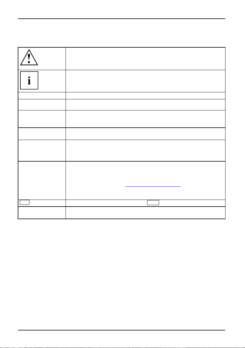
Notational conventions
Pay pa rticular attention to text marked with this symbol. Failure to
observe this warning may endanger your health, cause the equipment to
malfunction or lead to loss of data. The warranty does not cover defects of
the equipment caused by failure to follow these instructions.
indicates important information that is required to use the device properly.
►
This style
This style
This style
"This style"
Abc
This style
refers to an action which you must carry out.
indicates a result
flags data entered using the keyboard in a program dialog or command
line, e.g. your password (Name123) or a command to launch a program
(start.exe)
refers to information displayed by a program on the screen, e.g.:
Installation is completed
is for
• terms and texts in a software user interface, e.g.: ClickSave.
• names of programs or files, e.g. Windows or setup.exe.
is for
• cross-references to anot
• Cross-references to an external source, such as a web address: For
further information visit "
• indicates names of CDs and
materials, e.g.: "CD/DVD
refers to a key on the keyboard, e.g.:
flags concepts and text that are emphasised or highlighted, e.g.: Do not
switch off device
her section, e.g. "Safety information"
www.fujitsu-siemens.com"
DVDs as well as names and titles of othe r
Drivers & Utilities" or "Safety" manual
F10
2 A26391-K225-Z120-1-7619, edition 1
Page 11

Important notes
Take note of the safety hints provided in the "Safety" manua l, in the "Professional
Notebook" operating manual and in this manual.
Important notes
A26391-K225-Z120-1-7619, edition 1 3
Page 12
Ports and operating elem e nts
Ports and operating elements
Ports
This chapter presents the individual hardware components of your notebook. You c an obtain
an overview of the ports and operating elements of the notebook. Please familiarise yourself
with these components before you start to work with your notebook.
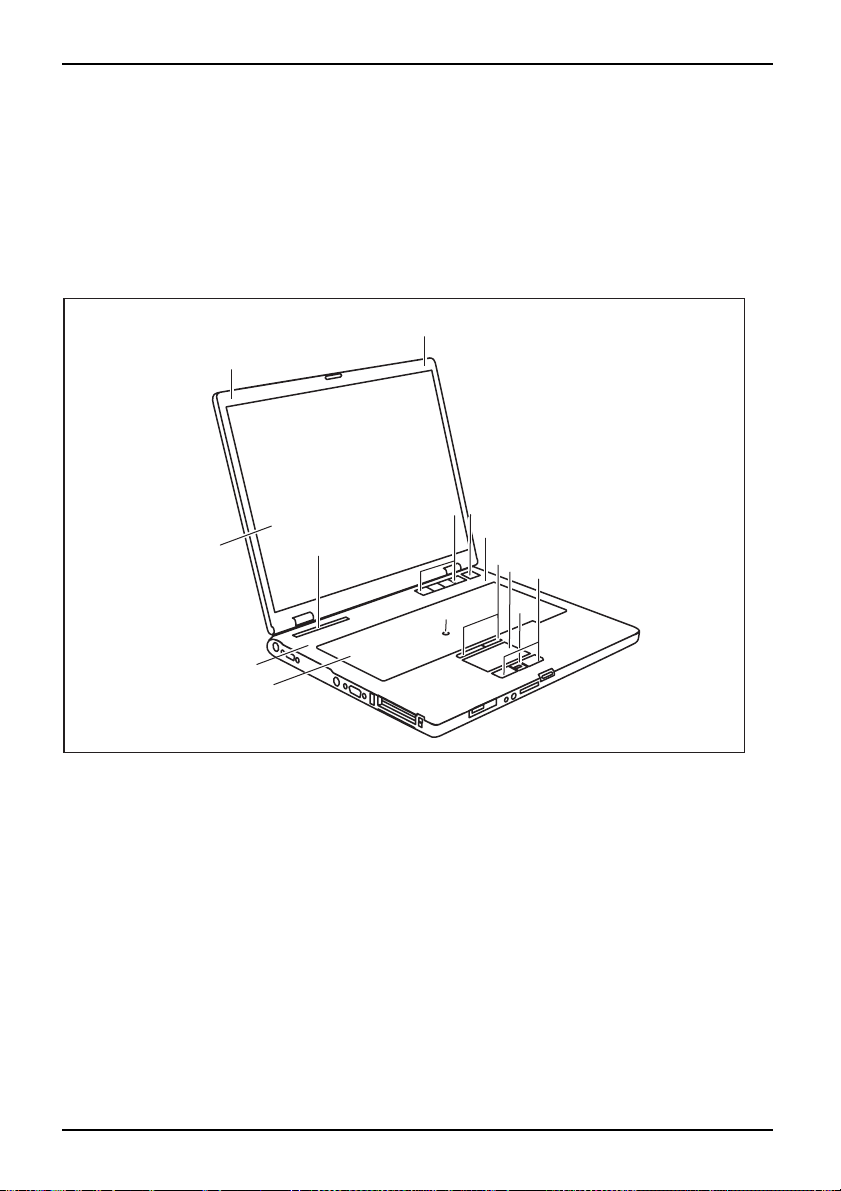
Opened Notebook
FrontViewLCDsc reenLoudspeakerKeyboardStatusindicatorpanelEasyLaunchkeysOn/OffswitchTouchSt ickTouchStickkeysTo uchpa dTouchpadkeys
1
1
7
6
2
5
3
9
10
12
8
3
4
1 = Microphone
2 = LCD screen
3 = Loudspeaker
4 = Keyboard
5 = Status indicator panel
6 = Easy Launch keys
4 A26391-K225-Z120-1-7619, edition 1
7 = ON/OFF button
8 = TouchStick (optional)
9 = TouchStick keys
10 = Touchpad
11 = Scroll key
12 = Touchpad keys
11
Page 13

Left side
ViewLeftsideDCINjackSerialportS-VideooutsocketMonitorportUSBportSmartCardreaderPCcardslotExpressCardsl ot
Ports and operating elemen ts
1
2 43 5 6 7 8 9
1=DCINjack
2 = Serial port
3 = S-Video out socket
4 = Monitor port ( VGA)
5=USBport
Front
ViewFront
6 = SmartCard reader
7 = PC card slot
8 = ExpressCard slot
9 = Card eject button
12 43 5
1 = ON/OFF button f or radio components
2 = Headphone port
4 = Memory card slot
5 = Screen lock
3 = Microphone port
A26391-K225-Z120-1-7619, edition 1 5
Page 14

Ports and operating elem e nts
Right side
RightsideViewUSBportsModuleModemp ortKensingtonLock
1
1 = USB ports
2 = Module
3 = Eject lever for module
2 43 5
4 = Modem connection (optional)
5 = Kensington Lock
Rear
ViewRearParallelportLANport
1 = Parallel port 2 = LAN port
1
2
6 A26391-K225-Z120-1-7619, edition 1
Page 15

Underside
UndersideBatteryreleaseBatteryPortforportreplicatorMemorymoduleHarddisk
Ports and operating elemen ts
4
3
2
5
1
6
1 = Battery release
2 = Battery
3 = Port for port replicator
4 = Battery release
5 = Cover for memory modules
6 = Cover for hard disk
A26391-K225-Z120-1-7619, edition 1 7
Page 16

Ports and operating elem e nts
Switching on the notebook
2
1
► Press the release bu tton (1), and unfold
the LCD screen upwards (2).
► Press the ON/OFF butt
1
2
Windows XP:
You can configure the ON/OFF button under Start - (Settings) - Control Panel Performance and Maintenance - Power Options - Advanced.
Windows Vista:
You c a n c o n figure the ON/OFF button under Start symbol - (Settings) Control Panel - Mobile PC - Power Options.
If you have assigned a password, you must enter this when requested to do so, in
order to start the operating system password. You can find more information in the
"Professional Notebook" operating instructions, "Security functions" section.
the notebook on.
The power-on indicator of the notebook
appears in the status indicator panel (2).
on (1) to switch
8 A26391-K225-Z120-1-7619, edition 1
Page 17

Ports and operating elemen ts
Switching off the Notebook
► Close all programs and shut down your operating system (please see operating system manual).
If the notebook cannot be shut down properly, press and hold the ON/O F F button for
approximately four seconds. The notebook will switch off. Any unsaved data may be lost.
► Close the LCD screen so that it
locks into place.
A26391-K225-Z120-1-7619, edition 1 9
Page 18

Ports and operating elem e nts
Status indicator panel
Statusindicatorpanel
The status indicator panel is a small LCD panel on which various symbols appear. These symbols
provide information about the status of the power supply, the drives, and the keyboard functions.
Power-on indicator
CD/DVD indicator
Power indicator Hard disk indicator
Battery charging indicator
PC card/ExpressCard
indicators
First battery indicator Num Lock indicator
Second battery indicator Caps Lock indicator
Radio components indicator
Scroll Lock indicator
The meanings of the symbols are as follows:
Power-on indicator
-onindicator
ator
Power
Indic
• Indicator lights up: The notebook is switched on.
• The indicator flashes (1 second on/ 1 second off). The notebook is in suspend
mode
• The indicator does not light up: The notebook is switched off.
Power indicat or
erindicator
icator
Pow
Ind
Indicator lights up: The mains adapter is supplying power to the notebook.
10 A26391-K225-Z120-1-7619, edition 1
Page 19

Ports and operating elemen ts
Battery charging indicator
BatterychargingindicatorIndicator
• Indicator lights up: The battery is charging.
• The indicator does not light up: The battery is either too hot or too cold to
be charged.
Battery indicators
IndicatorIndicatorBattery
The charging state of the batteries is shown by tw o battery indicators. 1 indica tes
that the information applies to the first battery in the battery compartment. 2
indicates that the information applies to the second battery in the module bay.
indicates that the battery is 0 % to 25 % charged.
indicates that the battery is 25 % to 50 % charged.
indicates that the battery is 50 % to 75 % charged.
indicates that the battery is 75% to 100% charged
Radio componen ts indicator
IndicatorIndicatorBluetoothIndicatorWirelessLAN
• Indicator lights up: one o r more radio components are active.
CD/DVD indicat or
IndicatorCD/DVDindicator
• Indicator lights up: The CD/DVD in the optical drive is being accessed. You
may only remove the CD/DVD when the indicator is dark.
• Indicator flashes: A CD/DVD is being inserted or removed.
Hard disk indicator
ator
Harddiskindic
Indicator
Indicator lights up: The hard disk drive of the notebook is being accessed.
PC card/ExpressCard indicators
IndicatorIndicatorPCCardExpressCard
Indicator lights up: A PC c ard or an ExpressCard is be
Num Lock indicator
IndicatorNumLock
Indicator lights up: The
Num
key has been pressed. The virtu
activated. You can output the characters located at the
Caps Lock indicator
IndicatorCapsLock
ing accessed.
al numeric keypad is
upper right on the keys.
Indicator lights up: The Caps Lock key has been pressed. All the characters you
type appear in upper case. In the case of overlay keys, the character printed on the
upper left of the key appears when that key is pressed.
Scroll Lock indicator
IndicatorScrollLock
Indicator lights up: The key combination
Fn+Scr
has been pressed. The effect
this key has varies from programme to programme.
A26391-K225-Z120-1-7619, edition 1 11
Page 20

Ports and operating elem e nts
Key combinations
The following description of key combinations refers to functions when using
Microsoft Windows. Some of the following key combinations may not function in
other operating systems and with some device drivers.
Key combinations are entered as follows:
► Press and hold the first key in the combination.
► While holding the first key down, press the other key or keys in the combination.
The key combination
Ctrl+Alt Gr
or
external keyboards that do not not feature a
Sleep mode
Fn+F1Sleepmode
This key combination is used to activate the susp end mode (S3).
Enable/disable loudspeakers
Fn+F3LoudspeakersLoudspeakers
This key combination switches your notebook’s loudspeakers off and on.
An audible signal will be produced when the loudspe akers are switched on.
Switch the touchpad on/off (if configured accordingly in BIOS)
Fn+F4TouchpadLoudspeakers
This key combination enables and disables the touchpad.
Enlarge display
Fn+F5DisplayFull-screenm ode
This key combination enlarges the screen to the full-screen mode or switches
it back to the normal m ode.
Decrease screen brightness
Fn+F6Screenbrightness
This key combination decreases the brightness of the screen.
Increase screen brightness
Fn+F7Screenbrightness
This key combination increases the brightness of the screen.
Decrease volume
Fn+F8Volume
This key combination reduces the volume of the integrated loudspeakers.
Ctrl+Alt
Fn
key.
canbeusedon
12 A26391-K225-Z120-1-7619, edition 1
Page 21

Ports and operating elemen ts
Volume increase
Fn+F9Volume
This key combination raises the volume of the integrated loudspeakers.
Toggle output screen
Fn+F10Toggleoutput screen
If an external monitor is connected, the monitor on which the output is to be
displayed can be selected with this key combination.
You can opt to use:
• just the notebook’s LCD screen
• just the external monitor
• both the LCD screen and the external monitor
C
+
Ctrl
AltCtrl
++
Halt current operation
Ctrl+C
This key combination can be used to hal
without clearing the keyboard buff
t an operation instantly
er.
Switch between open applications
With this key combination you can switch between several open
applications.
Alt+Tab
Del
SysRq
Performwarmboot
This key combination triggers a res
press and hold both the
Ctrl
and
key. This will cause the Task Mana
combinationmustbepressedase
Ctrl+Alt+DelWarmboot
et and reboots the notebook. First
Alt
key, th en
press the
ger to be displayed. The key
cond time to reboot the system.
Back tab
This key combination moves the curs
stop.
Shift+TabBacktab
or back to the previous tabular
Key combinations using the Windows keys are detailed in the manual
for your operating system.
Del
A26391-K225-Z120-1-7619, edition 1 13
Page 22

Ports and operating elem e nts
Easy Launch keys
EasyLaunchkeys
Your notebook is equipped with four Easy Launch keys.
RE
Lock Workstation key
This key allows you to lock your workstation. However, you can also con figure this key as desired.
Mobility Center key
This button starts the Mobility Center. However, you can also configure this key as desired.
E key
The E key is a simple way of activating and deactivating power management functions (e.g.
reduce screen brightness), see the "Professional Notebook" manual.
R key (recovery)
Pressing the R key opens a dialog window in which you can backup or restore data.
Configuring Easy Launch keys
The Application Panel allows you to assign various functions to the Easy Launch keys.
Windows XP:
You will find the Application Panel under Start - (Settings) - C ontrol Panel - Additional
Control Panel Options - Application Panel.
Windows Vista:
You will find the Application Panel under Start symbol - Programs - Lifebook Application Panel.
14 A26391-K225-Z120-1-7619, edition 1
Page 23

Ports and operating elemen ts
Removing and installing the bat
NotesBattery
Only use batteries approved by Fujitsu Siemens Computers for your notebook.
Never use force when inserting or removing a battery.
Make sure that no foreign bodies get into the battery connections.
tery
Removing the battery
► Switch the notebook off and pull the power plug out of the m ains socket.
Battery
► Close the LCD screen so that it locks i
► Disconnect all cables connected to the notebook.
► Turn your notebook over and place it on
an anti-slip cloth on this surface to p
nto place.
a stable, flat a nd clean surface. If necessary, lay
revent the notebook from being scratched.
1
3
2
► Slide the battery release in the direction of the arrow (1) and hold it in place.
The battery release is unlocked.
► Slide the hard disk carrier in the direction of the arrow (2) as far as it will go.
Aredfield appears on the battery release.
► Slide the ba ttery release in the direction of the arrow (1) again a n d hold it in place.
► Tilt the battery on the red field of the battery release to one side and lift
it out of the battery compartment (3).
A26391-K225-Z120-1-7619, edition 1 15
Page 24

Ports and operating elem e nts
Inserting the battery
1
2
► Insert the bat
direction of t
Battery
tery in the battery compartment at an angle and push it in the
he arrow (1) until it locks into place .
► Push the battery release latch in direction of the arrow (2).
16 A26391-K225-Z120-1-7619, edition 1
Page 25

Ports and operating elemen ts
SIM card
A SIM Card (Subscriber Identity Module) is a chip card which is inserted in a mobile
telephone or notebook to enable access to a mobile radio network.
Follow the instructions supplied by the provider of the SIM card.
Inserting the SIM card
► Switch the notebook off and pull the power plug out of the m ains socket.
► Close the LCD screen so that i
► Disconnect all cables connected to the notebook.
► Turn your notebook over and p
an anti-slip cloth on this su
► Remove the battery (see Section "
t locks into place.
lace it on a stable, flat a nd clean surface. If necessary, lay
rface to prevent the notebook from being scratched.
Removing the battery", Page 15).
► Insert the SIM card into the s
the angled corner is at the f
pointing towards the slot a
facing dow nwards (1). Ensu
SIM card snaps audibly int
ront left when
nd the chip is
oplace.
re that the
lot so that
► Reinstall the battery (see "
► Turn the notebook the right way up and place it on a flat surface.
► Reconnect the cables that you disconnected previously.
A26391-K225-Z120-1-7619, edition 1 17
Inserting the battery", Page 16).
Page 26

Ports and operating elem e nts
Removing a SIM card
► Switch the notebook off and pull the power plug out of the mains socket.
► Close the LCD screen so that it locks into place.
► Disconnect all cables connected to the notebook.
► Turn your notebook over and place it on a stable, flat and clean surface. If necessary, lay
an anti-slip cloth on this surface to prevent the notebook from being scratched.
► Remo v e the battery (see Section "
1
Removing the battery", Page 15).
► Push the SIM card inwards slightly to
ejectitfromtheslot(1).
► Pull the SIM card out of the slot in the
direction of the arrow (2).
2
► Reinstall the battery (see "
► Turn the notebook the right way up and place it on a flat surface.
► Reconnect the cables that you disconnected previously.
Inserting the battery", Page 16).
18 A26391-K225-Z120-1-7619, edition 1
Page 27

Ports and operating elemen ts
Radio components: UMTS (optional)/wireless LAN/Bluetooth
WirelessLANBluetoothUMTS
The modules for radio components are switched off during shipping.
The installation of a wireless LAN, Bluetooth or UMTS module not approved by Fujitsu
Siemens Computers GmbH voids the permits (CE!, FCC) issued for this device.
Fujitsu Siemens Computers GmbH has printed the correct permit number for
all factory-installed radio components on the rating plate.
Switching the radio components
If you switch off the radio components, the Bluetooth and UMTS modules are powered
off and the wireless LAN transmission unit (antenna) is switched off.
The Wireless Selector enables you to switch the various radio components on and off.
You can also deactivate the radio components individually in the BIOS setup.
Pay attention to the additional sa fety notes for devices with radio
components provided in the "Safety" manual.
Details on using the wireless LAN are contained in the online help for your
wireless LAN software and in the "Wireless LAN" manual. (The "Wireless LAN"
manual can be found on the "Drivers & Utilities" CD/DVD.)
You c a n find more information on how to use Bluetooth on the CD you
received with your Bluetooth software.
You can obtain more information on UMTS from your service provider.
on and off
► Slide the ON/OFF button into the "ON"
position to activate the radio components.
WirelessLANWirelessLANBluetoothBluetooth
or
► Slide the ON/OFF button to the
"OFF" position to deactivate the
radio components.
A26391-K225-Z120-1-7619, edition 1 19
Page 28

Removing and installing components
during servicing
Removing and installing compo
nents
during servicing
Only qualified technicians should repair your notebook. Unauthorised
opening or incorrect repair may greatly endanger the user (electric shock,
fire risk) and will invalidate your warranty.
Servicing
Components
You may remove and install the components described in this chapter yourself
after consulting the Hotline/Help Desk.
If you remove and install component s without consulting the Hotline/Help
Desk, then the warranty of your notebook will be voided.
Notes on installing and removing boards and components
• Switch the notebook off and pull the power plug out of the mains socket.
• Remove the b attery.
• Take care when you use the locking mechanisms on the battery and any other component.
• Never use sharp objects suc
NotesBoardESD
Boards with electrostatic sensitive d evices (ESD) are marked with the label
shown.
When handling boards fitted with ESDs, you must always observe the following
points:
• You must always discharge static build up (e.g. by touching a grounded
object) before working.
• The equipment and tools you use must be free of static charges.
• Remove the power plug from the mains supply before inserting o r removing
boards containing ESDs.
• Always hold boards with ESDs by their edges.
• Never touch pins or conductors on boards fitted with ESDs.
h a s screwdrivers, scissors or knives as leverage to remove covers.
20 A26391-K225-Z120-1-7619, edition 1
Page 29

Removing and installing components
during servicing
Hard disk
The hard disk is the most important storage medium of your notebook. You can work considerably
faster and more efficiently if you copy applications and files fro m CDs to your hard disk.
When the hard disk is acce ssed, the hard disk indicator lights up in the status
indicator panel, see "
Removing the hard disk
► Switch off your notebook and disconnect the power plug from the mains.
Harddisk
► Close the LCD screen so that it locks into place.
► Disconnect all cables connected to the notebook.
► Turn your notebook over and place it on a stable, flat and clean surface. If necessary, lay
a non-slip cloth on this surface to prevent the notebook from being scratched.
► Remove the battery (see "
Status indicator panel", Page 10.
Removing the battery", Page 15).
1
2
► Remov e the screw (1).
► Lift the cover off the notebook (2).
A26391-K225-Z120-1-7619, edition 1 21
Page 30

Removing and installing components
during servicing
a
1
► Grasp the hard disk by the pulling aid (a) and pull in the direction indicated by the arrow (1).
The hard disk separat
► Lift the hard disk out of the hard disk compartment (2).
► Loosen the screws (1) of the hard disk carrier.
► Remove the hard disk from the hard disk carrier.
es from the disk connector.
1
1
2
1
1
22 A26391-K225-Z120-1-7619, edition 1
Page 31

Installing the hard disk
Removing and installing components
during servicing
1
► Insert the hard disk i
► Fasten the hard disk carrier with the screws (1).
nto the hard disk carrier.
1
a
1
1
1
b
2
3
► Insert the hard disk at an angle into the hard dis k compartment (1). Ensure that the eyelet
(a) on the hard disk holder is inserted correctly into the existing opening.
► Place the har
► Pull the hard disk by the pulling aid (b) in the direction indicated by the arrow (3) until
the hard disk can be felt to latch into the hard disk connector.
► Lay the pull
A26391-K225-Z120-1-7619, edition 1 23
d disk in the hard disk compartment (2).
If the pulling aid (b) sticks out too far from the hard disk, it will not be
possible to fasten the hard disk cover correctly.
ing aid (b) down flat on the hard disk.
Page 32

Removing and installing components
during servicing
2
1
► Place the cover on its mounting location (1), ensuring it snaps into place.
► Fasten the cover with the screw (2).
► Install the battery again (see "
► Turn the notebook the right way up and place it on a flat surface.
► Reconnect the cables that you disconnected previously.
Inserting the battery", Page 16).
24 A26391-K225-Z120-1-7619, edition 1
Page 33

Removing and installing components
during servicing
Removing and installing memory
MainmemoryMemoryexpansionMemoryupgradeSystem e xpansion
The notebook will not start without memory modules, as no fixed RAM is installed.
Your notebook supports dual-channel DDR2 technology.
The dual-channel DDR2 technology can only be u sed with two identical
memory modules. When two different memory modules are installed, only
"single-channel" performance is supported.
If you are asked by the Hotline/Help Desk to remove and install the memory
modules yourself, proceed as follows:
Pay attention to the relevant safety notes p rovided in the "Important notes" chapter.
The notebook must be switched off when installing/removing the memory
modules, it must not be in Suspend mode.
Only use approved memory expansion modules in your notebook
(see Section "
Never use force w hen installing or removing memory modules.
Make sure that foreign objects do not fall into the memory expansion c ompart m ent.
Individual components (e.g. the p
during operation. Therefore, w
switching off the notebook bef
Otherwise, there is a risk of su
As some non-ESD safe component
on installing and removing boa
► Switch your notebook o ff and unplug the mains adapter from the mains outlet.
► Close the LCD screen so that it locks into place.
► Disconnect all cables connected to the notebook.
► Turn your notebook over and place it on a stable, flat and clean surface. If necessary, lay
an anti-slip cloth on this surface to prevent the notebook from being scratched.
► Remove the battery (see "
Technical data", Page 28).
rocessor heat sink) can become very hot
e recommend that you wait one hour after
ore removing or installing the memory modules.
ffering burns!
s are exposed, please observe the section "
rds and components", Page 20.
Removing the battery", Page 15).
modules
Notes
A26391-K225-Z120-1-7619, edition 1 25
Page 34

Removing and installing components
Removing the cover
during servicing
► Remove the screws (1).
► Pull the cover off the notebook (2).
1
2
Removing memory modules
3
2
1
1
Installing a memory module
2
1
► Carefully push the
clips outwards (1
MemoryexpansionMemorymodule
The memory module snaps upwards (2).
► Pull the memory modul
in the direction of th
► Insert the memory module with the contacts
and the recess (a) facing the slot (1).
MemoryexpansionMemorymodule
► Carefully push the memory module
downwards until you feel it click
into place (2).
two mounting
).
eoutofitsslot
e arrow (3).
a
26 A26391-K225-Z120-1-7619, edition 1
Page 35

Attaching the cover
Removing and installing components
► Place the cover in the correct
mounting position (1).
► Secure the cover with the screws (2).
during servicing
2
► Reinstall the battery (see "
► Turn the notebook the
► Reconnect the cables that you disconnected previously.
1
Inserting the battery", Page 16).
right way up and place it on a flat surface.
A26391-K225-Z120-1-7619, edition 1 27
Page 36

Technical data
Technical data
Notebook
Technicaldata
General
Processor
Main memory
Possible modules:
Electrical data
Regulations complied with
Protection class II
Maximum power draw
(notebook on with battery charg
LCD screen
Screen size 15 inch TFT X GA (1024 x 768)
Max. resolution:
Graphics card
Chip Intel® GMA X3000
Video memory (VRAM) Shared Memory
Audio
Soundchip HD Audio Codec ALC262
Dimensions/weight
Width x Depth x Height (front/ba
Weight with battery and optical
Input d evices
Keyboard 86 keys
Touchpad 1 touchpad, 2 touchpad keys, 1 s
TouchStick
Slots
ExpressCard slot 1 x ExpressCard/34 or ExpressCa
PC card slot (CardBus/PCMCIA) 1 x PCMCIA type I or II
SmartCard slot
SIM card socket
Memory card slot
ing)
ck)
drive
Intel Core2 Duo Processor
512 MB, 1 GB or 2 GB DDR2-667, SO-DIMM
• Second battery
• Second hard disk drive
• Super-multi format DVD burner with double
layer support
• Weight Saver
CE, EN60950, TBR 21
80 W
15 inch TFT SXGA+ (1400 x 1050)
1400 x 1050 / 16 MI. colours
External up to 1920 x 1200
approx. 329 mm x 274 mm x 38 mm
approx. 2.7 kg
1 touchstick, 2 touchstick key
1x
1x
1xSDorMScard
s
croll key
rd/54
28 A26391-K225-Z120-1-7619, edition 1
Page 37

Ports
Microphone port 3.5 mm mono mini-jack
Headphone port 3.5 mm stereo mini jack
Infrared interface
IrDA 1.1
Modem connection (optional) Connector, RJ11
USB port 4 x USB 2.0
Parallel port 25-pin socket
Monitor port 15-pin socket
Serial port
LAN port
9-pin plug
Socket, RJ45
S-Video out socket 7-pin mini DIN female connector
Docking port 100-pin
Environmental conditions
Environment class DIN IEC 721
Mechanism class DIN IEC 721
3K2
7M2
Temperature:
Operation 5 °C ... 35 °C
Transport
-15 °C ... 60 °C
Technical data
The data sheet of this notebook contains further technical data. The data sheet
can be found on your notebook or on the Internet at "
www.fujitsu-siemens.com"
or on the "Drivers & Utilities" CD/DVD.
Battery
ata
Technic ald
LIFEBOOK E8310
6-cell rechargeable battery 1 6-cell rechargeable battery 2
Rated voltage 10.8 V 10.8 V
Rated capacity 56.2 Wh 41 Wh
LIFEBOOK E8410
8-cell rechargeable battery 6-cell rechargeable battery
Rated voltage 14.4 V 10.8 V
Rated capacity 74.9 Wh 41 Wh
The operating time depends on the device equipment, the active
applications and the energy saving settings.
A26391-K225-Z120-1-7619, edition 1 29
Page 38

Technical data
Mains adapter
Technicaldata
Primary
Rated voltage
Rated frequency 50 Hz to 60 Hz (automatic)
Secondary
Rated voltage 19 V
Additional mains adapters and an power cables are can be orde red at any time.
100 V or 240 V (automatic)
30 A26391-K225-Z120-1-7619, edition 1
Page 39

Index
Index
A
Alt+Tab 13
B
Back tab 13
Battery 7
important notes 15
indicator 11
inserting 16
removing 15
Battery charging indicator 11
Battery release 7
Bluetooth 19
Indicator 11
Switching off 19
Switching on 19
Board 20
C
Caps Lock
indicator 11
CD/DVD indicator 11
Components
installing / removing 20
Ctrl+Alt+Del 13
Ctrl+C 13
D
DC IN jack 5
Display
enlarge 12
E
Easy Launch keys 4, 14
ESD 20
ExpressCard
indicator 11
ExpressCard slot 5
F
Fn + F1 12
Fn + F10 13
Fn + F3 12
Fn + F4 12
Fn + F5 12
Fn + F6 12
Fn + F7 12
Fn + F8 12
Fn + F9 13
Front 4–5
Full-screen mode 12
H
Hard disk 7
removing 21
Hard disk indicator 11
I
Indicator
Battery charging indicator 11
Bluetooth 11
Caps Lock 11
CD/DVD 11
ExpressCard 11
First battery 11
Hard disk indicator 11
Num Lock 11
PC-Card 11
Power indicator 10
Power-on indicator 10
Radio components 11
Scroll Lock 11
Second battery 11
Wireless LAN 11
K
Kensington Lock 6
Keyboard 4
L
LAN port 6
LCD screen 4
Left side 5
Loudspeaker 4
Loudspeakers
disable 12
enable 12
M
Main memory 25
Memory expansion 25
installing 26
removing 26
Memory module 7
installing 26
removing 26
A26391-K225-Z120-1-7619, edition 1 31
Page 40

Index
Memory upgrade 25
Modem port 6
Module 6
Monitor port 5
N
Notes
battery 15
boards 20
Num Lock
indicator 11
O
On/Off switch 4
P
Parallel port 6
PC Card
indicator 11
PC card slot 5
Port for port replicator 7
Ports 4
Power indicator 10
Power-on indicator 10
R
Rear 6
Right side 6
S
S-Video out socket 5
Screen brightness
decrease 12
increase 12
Scroll Lock
indicator 11
Serial port 5
Servicing 20
Shift+Tab 13
Sleep mode
activating 12
SmartCard reader 5
Status indicator panel 4, 10
System expansion
memory expansion 25
T
Technical data
Battery 29
Mains adapter 30
notebook 28
To ggle output screen 13
Touchpad 4
disable 12
Touchpad keys 4
To u c h St i c k 4
TouchStick keys 4
U
UMTS 19
Underside 7
USB port 5
USB ports 6
V
View
front 4–5
Left side 5
rear 6
Right side 6
Volum e
decrease 12
increase 13
W
Warm boot 13
Wireless LAN 19
Indicator 11
Switching off 19
Switching on 19
32 A26391-K225-Z120-1-7619, edition 1
 Loading...