

Fujitsu Siemens Computers FSC B17-1 Service Manual
FSC B17-1 Service Manual
1
SERVICE MANUAL
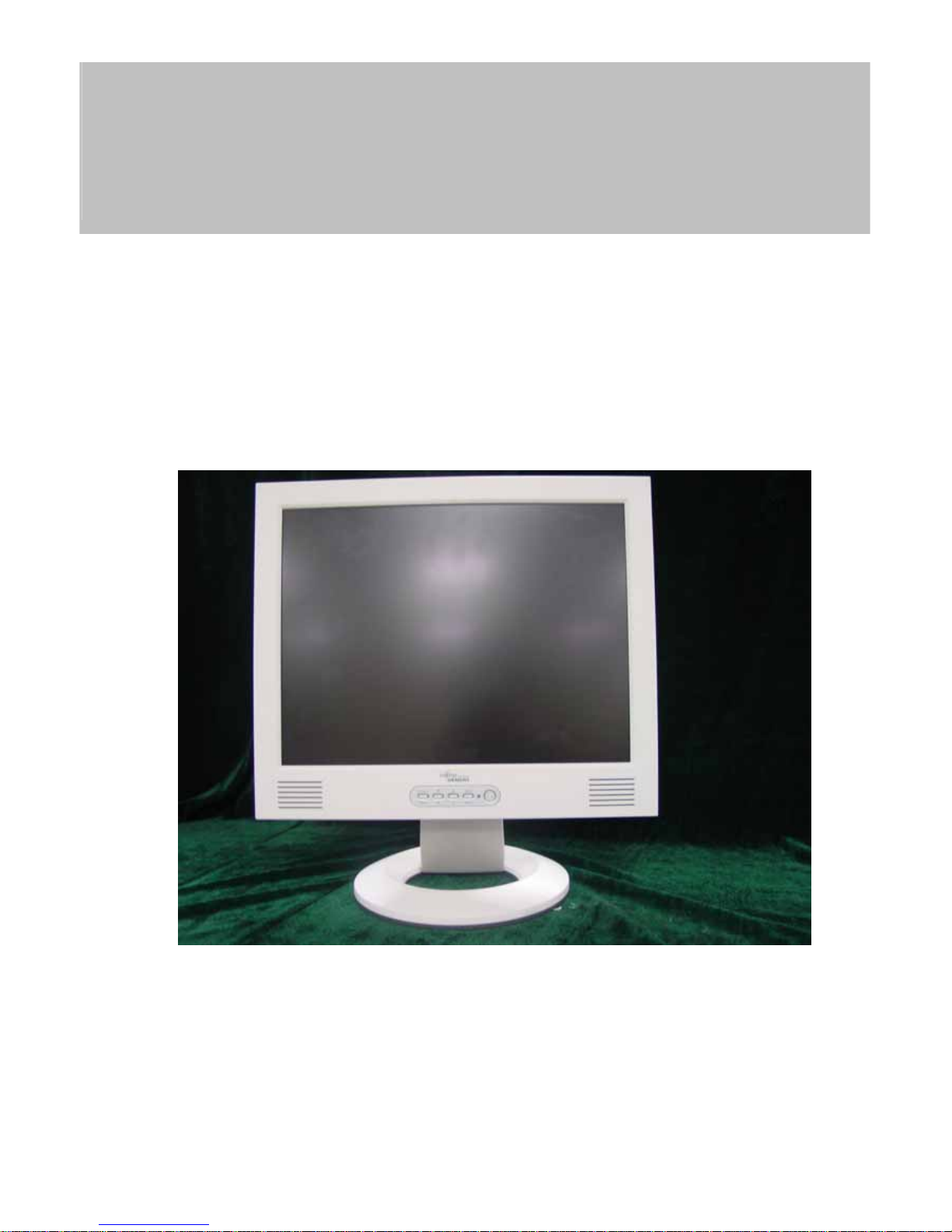
17” LCD Monitor
FSC B17-1
THESE DOCUMENTS ARE FOR REPAIR SERVICE INFORMATION ONLY. EVERY REASONABLE EFFORT
HAS BEEN MADE TO ENSURE THE ACCURACY OF THIS MANUAL; WE CANNOT GUARANTEE THE
ACCURACY OF THIS INFORMATION AFTER THE DATE OF PUBLICATION AND DISCLAIMS RE
LIABILITY FOR CHANGES, ERRORS OR OMISSIONS.

FSC B17-1 Service Manual
2
Table of Contents
Table of Contents -----------------------------------------------------------------2
1. MONITOR SPECIFICATIONS ----------------------------------------------------4
2. LCD MONITOR DESCRIPTION -----------------------------------------------5
3. OPERATING INSTRUCTIONS ------------------------------------------------6
3.1 GENERAL INSTRUCTIONS --------------------------------------------------6
3.2 CONTROL BUTTONS -----------------------------------------------------------6
3.3 ADJUSTING THE PICTURE --------------------------------------------------6
4. Input/Outpt Specification --------------------------------------------------------8
4.1 Input Signal Connector --------------------------------------------------------8
4.1.1 Analog D-SUB Connector ----------------------------------------------------8
4.2 Factory Preset Display Modes -----------------------------------------------8
4.3 Power Supply Requirements ----------------------------------------------10
4.3.1 Input Requirements ----------------------------------------------------------10
4.3.2 Output Requirements -------------------------------------------------------10
4.4 PANEL SPECIFICATION (Samsung ) -------------------------------------11
4.4.1 Panel Feature ----------------------------------------------------------------11
4.4.2 Display Characteristics --------------------------------------------------11
4.4.3 Optical Characteristics -----------------------------------------------------11
4.4.4 Parameter guide line for CCFL Inverter ------------------------------12
5. Block Diagram --------------------------------------------------------------------13
5.1 Monitor Exploded View ------------------------------------------------------13
5.2 Software Flow Chart -----------------------------------------------------------14
5.3 Electrical Block Diagram -----------------------------------------------------16
5.3.1 Main Board --------------------------------------------------------------------16
5.3.2 Inverter/Power Board ------------------------------------------------------17
6. Schematic ------------------------------------------------------------------------19

FSC B17-1 Service Manual
3
6.1 Main Board ----------------------------------------------------------------------19
6.2 Inverter/Power Board --------------------------------------------------------22
6.3 KeyPad Board -----------------------------------------------------------------24
7. PCB Layout -----------------------------------------------------------------------25
7.1 Main Board ---------------------------------------------------------------------25
7.2 Inverter/Power Board --------------------------------------------------------27
7.3 Keypad Board ------------------------------------------------------------------28
8. Maintainability --------------------------------------------------------------------28
8.1 Equirements and Tools Requirements ---------------------------------28
8.2 Trouble Shooting --------------------------------------------------------------29
8.2.1 Main Board --------------------------------------------------------------------29
8.2.2 Power/Inverter Board ------------------------------------------------------32
8.2.3 Key Pad Board ---------------------------------------------------------------34
9. White-Balance, Luminance adjustment --------------------------------35
10. EDIT Content ------------------------------------------------------------------36
11. BOM List --------------------------------------------------------------------------37
FSC B17-1 Service Manual
4
1. MONITOR SPECIFICATIONS
Driving system TFT Color LCD
LCD Panel Size 38.1cm(15.0")
Pixel pitch 0.297mm( H )x 0.297mm( V )
Viewable angle 130˚ (H) 90˚ (V)
Response time (typ.) 25 ms
Video Analog/DVI-D
Input Sync. Type H/V TTL Separate and Composite Sync.
H-Frequency 30kHz – 63kHz
V-Frequency 55-75Hz
Display Colors Over 16 million Colors
Dot Clock 80MHz
Max. Resolution 1024 x 768
Plug & Play VESA DDC2BTM
Power Consumption ON Mode
<35W
OFF Mode
<1W
Maximum Screen Size
Horizontal : 12.0”(304.128mm)
Vertical : 9.0”(228.096mm)
Power Source
90~264VAC,47~63Hz
Environmental
Considerations
Operating Temp: 5°C to 40°C
Storage Temp.: -5°C to 40°C
Operating Humidity : 10% to 80%
Weight (N. W.) Packaged 4.6Kgs Unit
Unpackaged 6.3Kgs Unit
FSC B17-1 Service Manual
5
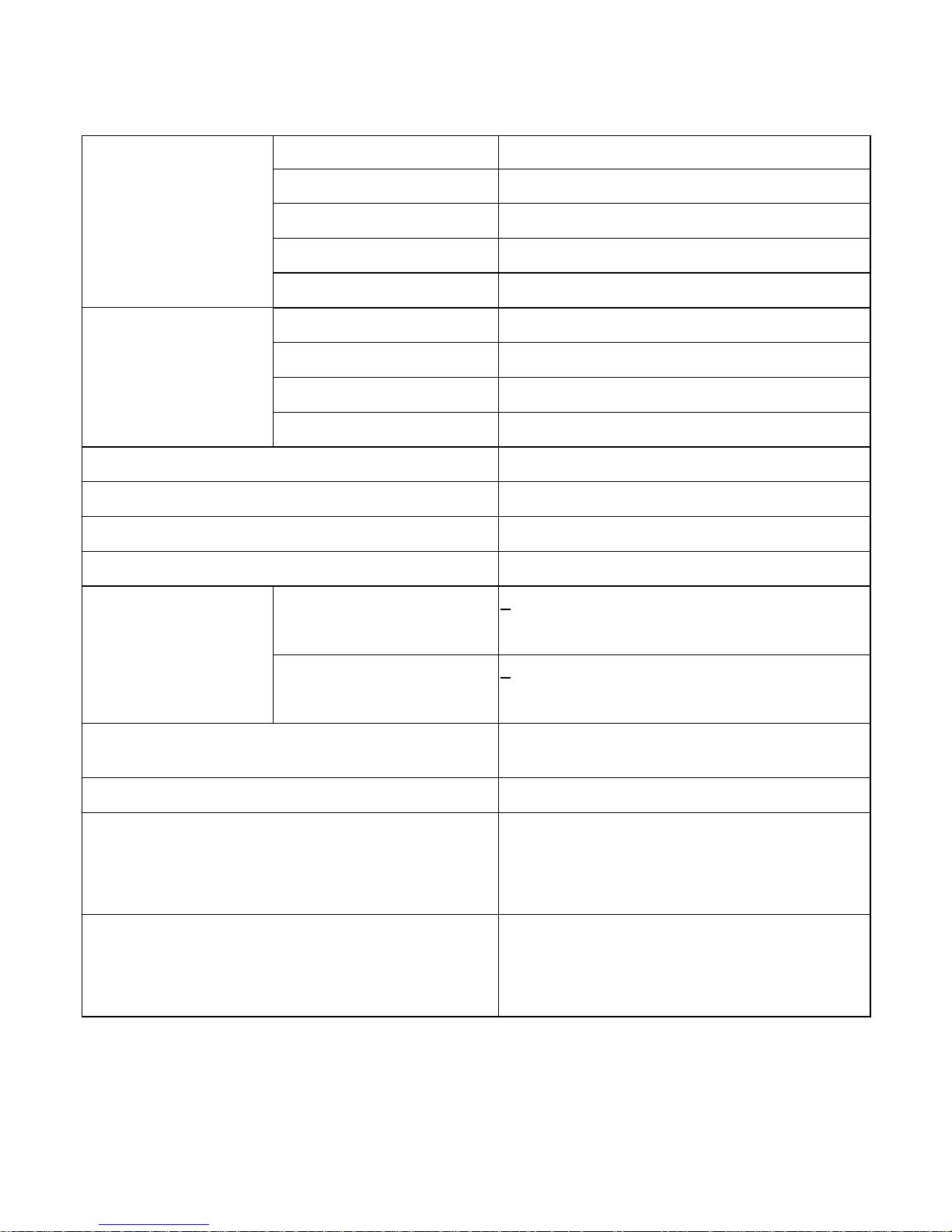
2. LCD MONITOR DESCRIPTION
The LCD MONITOR will contain an main board, an inverter/power board, keypad board and internal adapter which
house the flat panel control logic, brightness control logic and DDC.
The Inverter board will drive the backlight of panel and the DC-DC conversion.
The Adapter will provides the 12V DC-power to inverter/power board.
Power board
(
include:adapter,inverter)
Flat Panel and
CCFL backlight
Main Board
Keyboard
RS232 Connector
For white balance
adjustment in
factory mode
HOST Computer
CCFT Drive.
AC-IN
90V-264V
Video signal, DDC
Monitor Block Diagram
FSC B17-1 Service Manual
6
3. OPERATING INSTRUCTIONS
3.1 GENERAL INSTRUCTIONS
Press the power button to turn the monitor on or off. The other control buttons are located at front panel of the monitor. By changing these
settings, the picture can be adjusted to your personal preferences.
-
The power cord should be connected.
-
Connect the video cable from the monitor to the video card.
-
Press the power button to turn on the monitor, the power indicator will light up.
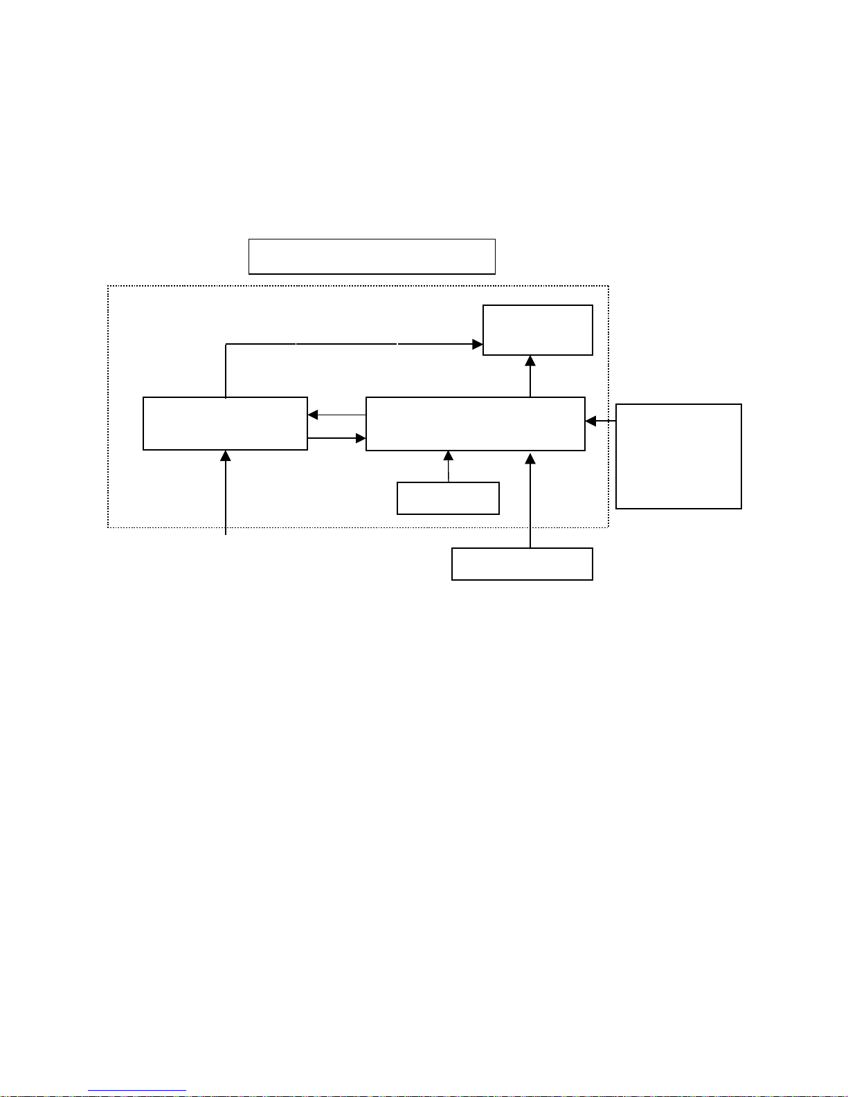
3.2 CONTROL BUTTONS
-
Power Button:
When pressed, the monitor enters the off mode, and the LED turns blank. Press again to restore normal status.
- Left / Right Button:
The Left/Right Button is used to control the monitor functions. Press to switch functions or adjust settings.
- Auto Adjust Key:
The Auto Adjust Key is used to automatically set the H Position, V Position, Clock and Phase.
- Power Indicator:
Green — Power On mode.
orange — Power Saving mode.
Blank —Power Off Mode.
1.Buttons for the OSD menu
(On-Screen-display)
2.Power indicator
3.ON/OFF switch
CONTROL Buttons
FSC B17-1 Service Manual
7
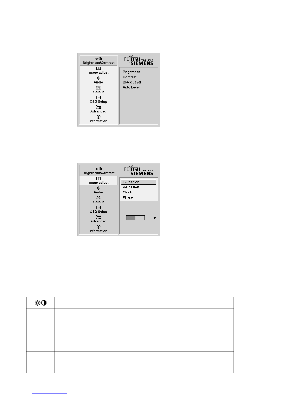
3.3 ADJUSTING THE PICTURE
To set the OSD menu, perform the following steps:
Briefly press the SELCT / MENU button to activate the OSD menu.
The main menu appears on the screen with icons for the setting functions.
The first symbol (
Brightness/Contrast) is highlighted.
necessary, press the
6
or 5 button to mark another icon (e.g. Image adjust).
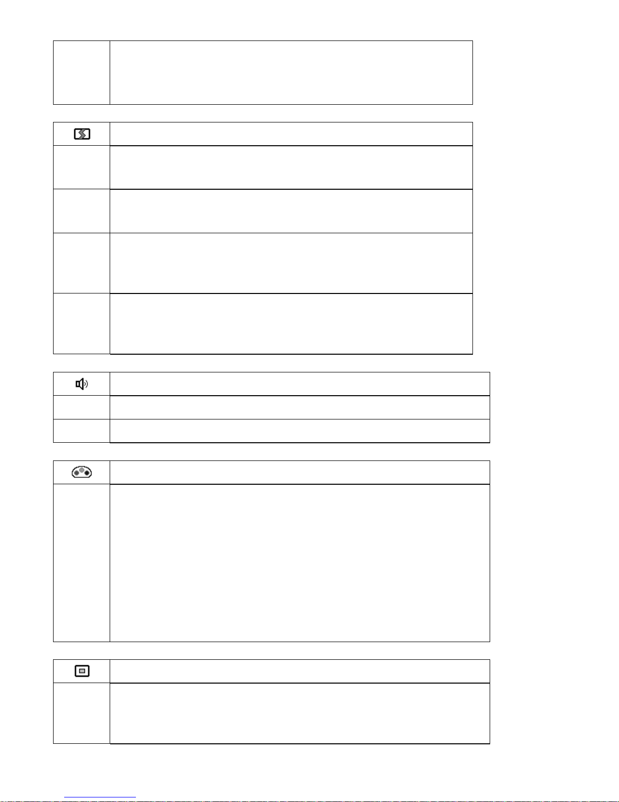
Press the SELECT/MENU button to select the highlighted icon.
The corresponding setting window (here: Image Adjust) is displayed.
The first symbol (H-Position) is highlighted.
If necessary, press the 6 or 5 button to mark the desired icon.
Press the SELECT/MENU button to select the highlighted function.
Press the 6 or 5 button to adjust the value for the selected function.
Press the EXIT/AUTO button to exit the function.
All changes are stored automatically.
Adjusting the brightness and contrast
Calling the Brightness / Contrast setting window.
Brightness
Setting the brightness of the display
With this function you change the brightness of the background lighting.
Contrast
Setting the contrast of the display
With this function you modify the contrast of bright colour tones.
Black Level
Setting the brightness of the display
With this function you modify the contrast of dark colour tones.
FSC B17-1 Service Manual
8
Auto Level
Setting the brightness of the display
With this function you can automatically set the contrast.
Press the SELECT/MENU button to activate function.
Adjusting size and position
Calling the Image adjust setting window
H-Position
Adjusting the horizontal position
With this function you move the picture to the left or to the right.
V-Position
Adjusting the vertical position
With this function you move the picture up or down.
Clock
Setting synchronisation
With this function you adjust the picture width to eliminate vertical picture
disturbances.
Phase
Eliminating picture interference
With this function you fine-tune your monitor to eliminate picture
interference.
Adjusting the volume
Calling the Audio setting window
Volume
Setting the volume for playback with the integrated loudspeakers
Mute
Switching the loudspeakers off or on
Setting colour temperature and colours
Calling the Colour setting window
Selecting the colour temperature
The "warmth" of the screen colours is set using the colour temperature. The
colour temperature is measured in K (= Kelvin). You can select from 6500 K,
9300 K,
Native and Custom Colour.
Native
Custom Colour
= original colour of the LCD display
= setting user-defined colours
In the user-defined setting you can change the colour ratios of the basic colours
(red, green, blue) as required.
Setting display of the OSD menu
Calling the OSD Setup setting window
Language
Setting language for the OSD menu
With this function you choose between English (default setting), French,
German, Italian and Spanish as the language for the OSD menu.
FSC B17-1 Service Manual
9
OSD
H-Position
Setting the horizontal position of the OSD menu
With this function you move the OSD menu to the left or to the right.
OSD
V-Position
Setting the vertical position of the OSD menu
With this function you move the OSD menu up or down.
OSD
Timeout
Setting the display duration of the OSD menu
With this function you select a value from 10 to 120 seconds.
If the set time expires without a setting being made, the OSD menu is
automatically faded out.
Setting the display format of the OSD menu
With this function you switch the OSD menu from portrait mode to landscape
mode and vice versa.
OSD
Rotation
O
ff
O
n
= the OSD Menu is displayed in portrait mode
= the OSD Menu is displayed in landscape mode
Setting functions in the "Advanced " menu
Calling the Advanced setting window
Input select
Selecting input signal
With this function you switch the screen from the analogue to the digital mode
and vice versa.
The condition is that the graphic card used supports this function.
Resolution
Notifier
Displaying monitor data
The optimum resolution for this monitor is 1280 x 1024pixels. With the function
activated (On), a message appears on the screen after approx. 30 seconds if a
different resolution is set.
Change the resolution to 1280 x 1024 to achieve optimum picture quality.
With the function deactivated (Off), no message appears.
Factory Recall
Activating the factory settings
With this function all settings are reset to the factory settings without prompting
for confirmation.
The Auto Processing message is displayed.
Displaying information
Calling the Information setting window
With this function the model designation, serial number,
resolution, H/V frequency, input signal and polarity of the
synchronisation signal are displayed.
FSC B17-1 Service Manual
10
4. Input/Outpt Specification
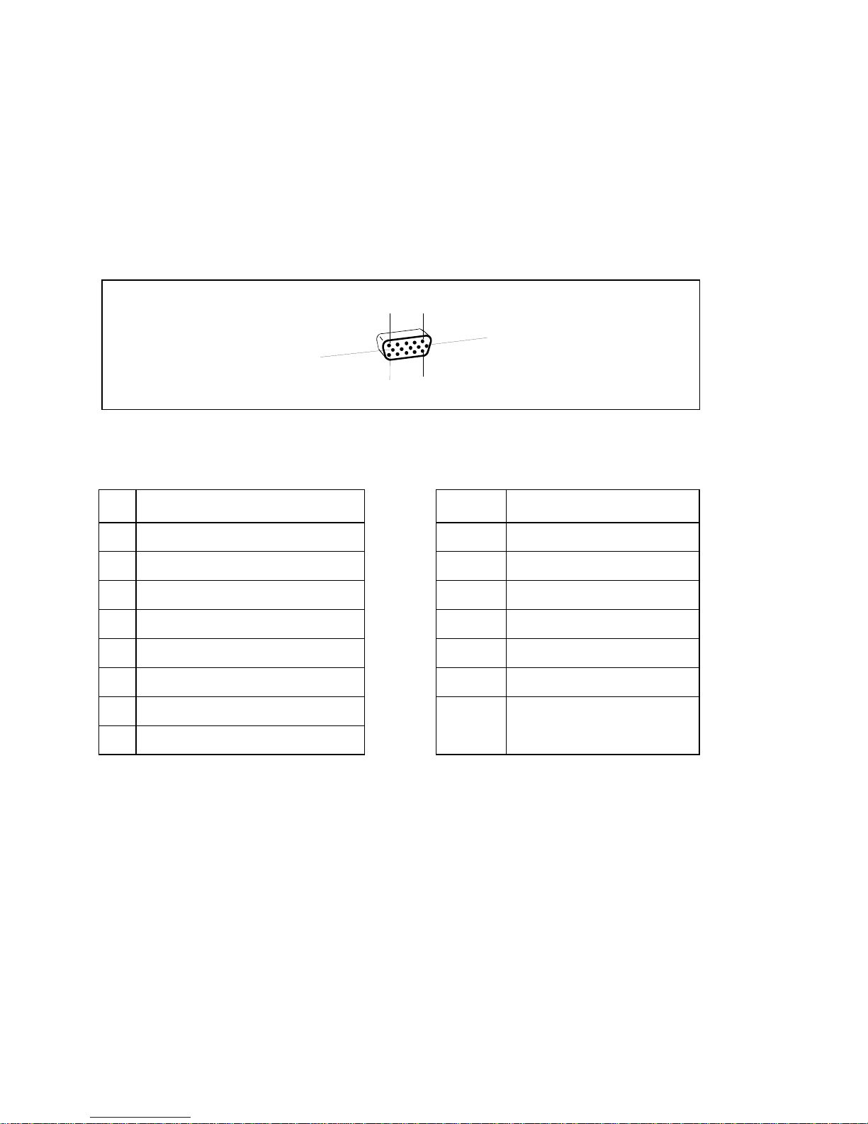
4.1 Input Signal Connector
4.1.1 Analog D-SUB Connector
1
5
6
10
11
15
Pin Meaning Pin Meaning
1 Video input red 9 +5 V (DDC)
2 Video input green 10 Sync. ground
3 Video input blue 11 Ground
4 Ground 12 DDC-Data
5 Ground 13 H. sync
6 Red video ground 14 V. sync
7 Green video ground 15 DDC Clock
8 Blue video ground

FSC B17-1 Service Manual
11
4.2 Factory Preset Display Modes
The following are the most frequently used of the preset operating modes:
Horizontal frequency Refresh rate Screen resolution
31.5 kHz
31.5 kHz
37.5 kHz
37.9 kHz
46.9 kHz
48.4 kHz
60.0 kHz
60.0 kHz
79.9kHz
70 Hz
60 Hz
75 Hz
60 Hz
75 Hz
60 Hz
75 Hz
60 Hz
75 Hz
720 x 400
640 x 480
640 x 480
800 x 600
800 x 600
1024 x 768
1024 x 768
1280 x 1024
1280 x 1024
For ergonomic reasons, a screen resolution of 1280 x1024 pixels is recommended. Because of the technology used
(active matrix) an LCD monitor provides a totally flicker-free picture even with a refresh rate of 60 Hz.
FSC B17-1 Service Manual
12
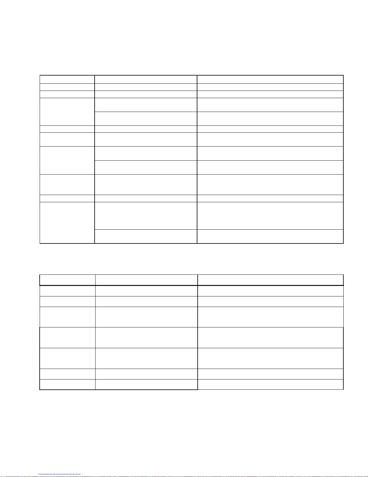
4.3 Power Supply Requirements
4.3.1 Input Requirements
PARAMETER RANGE CONDITION
Input Voltage 90 to 264VAC RMS Universal input full range
Input Frequency 47 Hz to 63 Hz 110V AC 60Hz; 220V AC 50 Hz
Input Current Less than 2.0 Amps RMS Input voltage 100 VAC RMS ; 60 Hertz. Parameter
must be reached within 3 seconds of turn-on.
Less than 1.0 Amps RMS Input voltage 220 VAC RMS ; 50 Hertz. Parameter
must be reached within 3 seconds of turn-on.
Input Power Less than 75 Watts
Power factor > 0.5 Input voltage 120 VAC RMS ; 60
Hertz
Inrush Current Less than 30 A peak Input voltage 100 VAC RMS ; 60 Hertz at all
Phase(0, 90, 180, 270 degree)
Less than 50 A peak Input voltage 240 VAC RMS ; 50 Hertz at all
Phase(0, 90, 180, 270 degree)
Input Fusing Fuse should be located internal to the
adapter, easily accessible when the
cover is removed
Fuse must be UL/CSA approved. Fuse value must no
have to change for 115 VAC or 230 VAC operation
Leakage Current Less than 3.5 mA Input voltage 240 Volts RMS ; 50 Hertz
Hi-Pot Primary to secondary 1.5KVAC for 1 Minute(leakage current 10mA)
1.8KVAC for 1 Minute(leakage current 10mA)
3.0KVAC for 1 Minute(leakage current 10mA)
without Y-cap & Coupling cap.
Primary to Saft Ground 1.5KVAC for 1 Minute(leakage current 10mA)
1.8KVAC for 1 Minute(leakage current 10mA)
4.3.2 Output Requirements
PARAMETER RANGE CONDITION
DC Out 12VDC ± 5% Min 0A Max 3.75A
Load Regulation 12.0V(12.12V) ± 5% 11.4 to 12.6VDC
Dynamic Load
Regulation
Any frequency up to 250Hz(duty
50%)
±5% for 10% to 100%, 100% to 10% load change for
+12Vdc
Ripple & noise 170mVpp at 12VDC Input voltage : 100VAC at 60Hz 240VAC at 50Hz
* Ripple and noise are measured.
Output current
p
rotection
less than 7.0A, more than 12.0A
at 12.0VDC
Current exceeds maximum rateing more than 20%
Leakage Current Less than 0.25 mA Input voltage 100 Volts RMS ; 50 Hertz
Less than 0.5 mA Input voltage 240 Volts RMS ; 50 Hertz
FSC B17-1 Service Manual
13
4.4 PANEL SPECIFICATION (CPT)
4.4.1 Panel Feature
-High contrast ratio, high aperture structure
-TN(Twisted Nematic) mode
-Wide viewing angle
-High speed response
-SXGA(1280 x 1024 pixels) resolution
-Low power consumption
-2 dual CCFTs(Cold Cathode Fluorescent Tube)
-DE(Data Enable) mode
-COMPACT SIZE DESIGN
4.4.2 Display Characteristics
Items Specification Unit
Display Area 337.92(H) x 270.336(V) mm
Driver element a-Si TFT active matrix
Display color 16.2M Colors
Number of pixels 1280 x 1024 pixel
Pixel Arrangement RGB vertical stripe
Pixel pitch 0.264(H) x 0.264(W) mm
Display Mode Normally White
4.4.3 Optical Characteristics
The optical characteristics are measured under stable conditions at 25℃ (Room Temperature):
Item Symbol Conditions Min. Typ. Max. Unit Note
Contrast Ratio
(Center of screen)
C/R 250 350 -
Rising
Tr
- 5 7
Response
Time
Falling Tf - 20 25
msec
Luminance of White
(Center of screen)
YL 200 250 - Cd/m2
Rx 0.633
Ry 0.354
Gx 0.292
Gy 0.598
Bx 0.145
By 0.107
Wx 0.305
Color
Chromaticity
(CIE 1931)
Coordinates (CIE)
Wy
Normal
ψ=0
θ=0
Viewing
Angle
Typ.
-0.03
0.338
TYP.
+0.03
Brightness Uniformity [%] 75 80 -

FSC B17-1 Service Manual
14
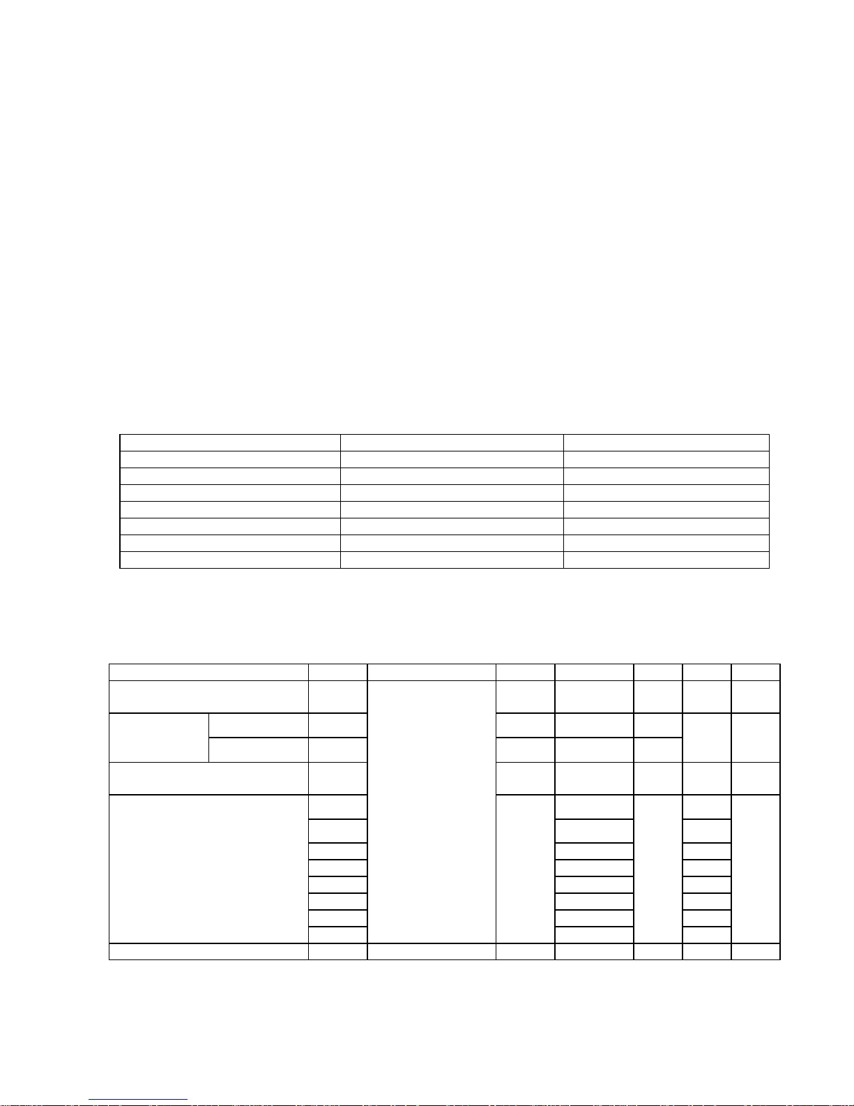
4.4.4 Parameter guide line for CCFL Inverter
INVERTERMAXBRINGTHNESS(Vadj:5.0v), LOAD=80KΩX4(ROOMTEMPERATURE25℃ ±4℃)
ITEM SYMBOL MIN. TYP. MAX. UNIT REMARK
Inputvoltage Vin 10.8 12 13.2 V
Inputcurrent Iin1700 2450 mA FOR4LOAD
OutputCurrent Iout 6.5 7.0 7.5 mA FOR1LOAD
Frequency
F 45.0 50.0 55.0 KHZ
FOR1LOAD
H.Vopen Vopen 1300 1450 1600 Vrms NOLOAD
H.VLoad Vload 480 580 680 Vrms
RL=80KΩ
Startvoltage Vst
1550 1650 1750 Vrms RL=CCFL
ProtectdelaytimePDT
0.4 1Sec
INVERTERMINBRINGTHNESS(Vadj:0.0v),LOAD=80KΩX4(ROOMTEMPERATURE25℃ ±4℃)
ITEM SYMBOL MIN. TYP. MAX. UNIT REMARK
inputvoltage Vin 10.8 12 13.2 V
inputcurrent Iin560 650 mA FOR4LOAD
OutputCurrent Iout 3.5 4.0 4.5 mA FOR1LOAD
Frequency
F 45.0 50.0 55.0 KHZ
FOR1LOAD
H.Vopen Vopen 1300 1450 1600 Vrms NOLOAD
Startvoltage Vst
1550 1650 1750 Vrms RL=CCFL
H.VLoad Vload 180 280 380 Vrms
RL=80KΩ

FSC B17-1 Service Manual
15
5. Block Diagram
5.1 Monitor Exploded View
FSC B17-1 Service Manual
16
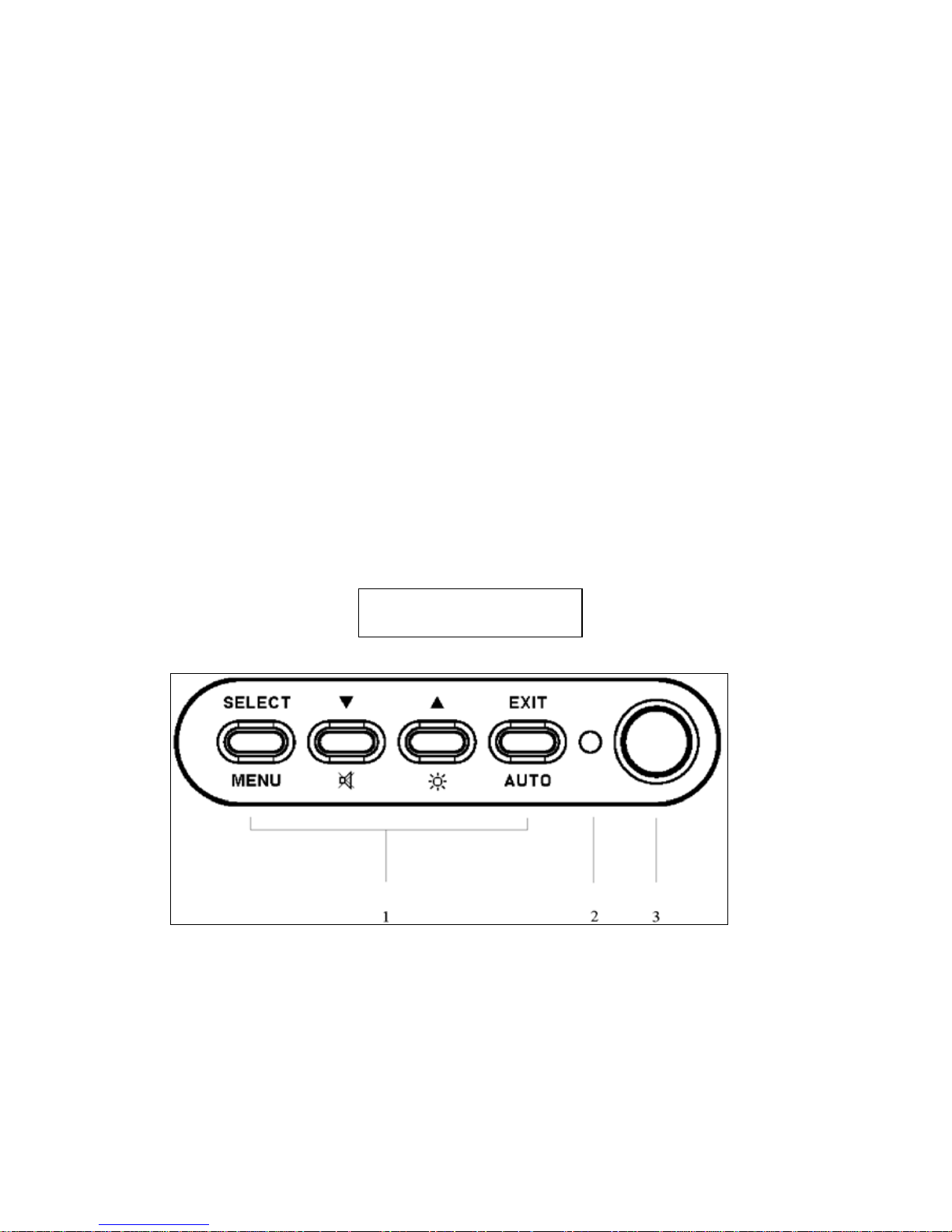
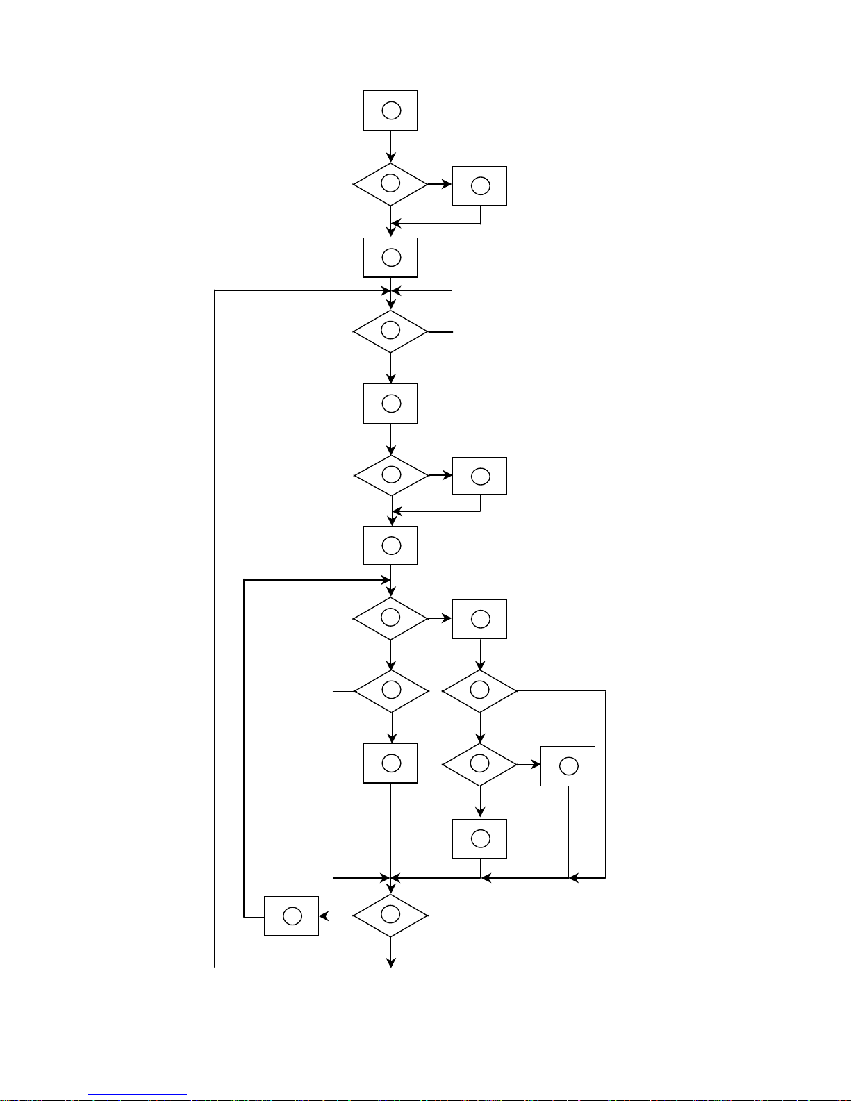
5.2 Software Flow Chart
1
2
5
10
12
7
643
8
9
141113
1516
1719
18

FSC B17-1 Service Manual
17
1) MCU initialize.
2) Is the eeprom blank ?
3) Program the eeprom by default values.
4) Get the PWM value of brightness from eeprom.
5) Is the power key pressed ?
6) Clear all global flags.
7) Are the AUTO and SELECT keys pressed ?
8) Enter factory mode.
9) Save the power key status into eeprom.
Turn on the LED and set it to green color.
Scaler initialize.
10) In standby mode ?
11) Update the life time of back light.
12) Check the analog port, are there any signals coming ?
13) Does the scalar send out a interrupt request ?
14) Wake up the scalar.
15) Are there any signals coming from analog port ?
16) Display "No connection Check Signal Cable" message. And go into standby mode after
the message disappear.
17) Program the scalar to be able to show the coming mode.
18) Process the OSD display.
19) Read the keyboard. Is the power key pressed ?
 Loading...