

Fujitsu Siemens Computers ESPRIMO Mobile D9500, ESPRIMO Mobile M9400, ESPRIMO Mobile U9200, ESPRIMO Mobile Series Easy Manual
Page 1

Professional Notebook English
EasyGuide
ESPRIMO Mobile Series
Page 2

Are there ...
... any technical problems or other questions that you would like help with?
Please contact:
• our Hotline/Help Desk (refer to the enclosed Help Desk List or go to:
"
www.fujitsu-siemens.com/s upport/")
• your sales partner
• your sales office
Additional information is contained in the Help Desk list and the "Warranty" manual. The
"Warranty" manual can be found on the supplied "Drivers & Utilities" CD/DVD.
Latest information on our products, tips, updates etc. can be found on our
website at: "
www.fujitsu-siemens.com"
Page 3

Page 4

This manual was produced byXerox Global Services
Published by
Fujitsu Siemens Computers GmbH
AG 09/07
Edition 2
Order no.: A26391-K230-Z120-1-7619
Page 5

ESPRIMO Mobile Series
Your ESPRIMO Mobile 1
Important notes
3
Ports and operati
ng elements
4
Removing and installing components
during servicing
23
Technical dat
a
30
Index
31
EasyGuide
Page 6

Adobe and Acrobat are trademarks of Adobe Systems Incorporated and may
be protected in certain countries.
The Bluetooth trademarks are the property of Bluetooth SIG, Inc., U.S.A. and
licensed to Fujitsu Siemens Computers GmbH.
Intel is a registered trademark, Core is a trademark of Intel Corporation, USA.
Kensington and MicroSaver are registered trademarks of ACCO World Corporation.
Macrovision is a trademark of Macrovision Corporation, USA.
Microsoft, MS, MS-DOS, Windows, Vista and Windows N T are registered
trademarks of Microsoft Corporation.
All other trademarks referenced are trademarks or registered trademarks of their
respective owners, whose protected rights are acknowledged.
Copyright © Fujitsu Siemens Computers G mbH 2007
All rights reserved, including rights of translation, reproduction by printing, copying
or similar methods, in part or in whole.
In the event of violations, perpetrators will be liable to prosecution for damages.
All rights reserved, including rights created by patent grant or registration of a utility model or design.
Subject to availability and technical m odifications.
Page 7

Contents
Contents
YourESPRIMO Mobile ................................................................. 1
Notational conventions .................................................................. 2
Importantnotes ........................................................................ 3
Portsand operatingelements .......................................................... 4
ESPRIMO Mobile U9200 ................................................................ 5
ESPRIMO Mobile M9400 ................................................................ 6
ESPRIMO Mobile D9500 ................................................................ 7
Switching on the notebook . . . . ........................................................... 8
Switching off the Notebook . . . ........................................................... 9
Statusindicators ........................................................................ 10
Keycombinations ....................................................................... 12
Camera (depending on noteb ook model) . . . . . . ............................................ 14
Removing and installing thebattery ....................................................... 15
Removing the battery ................................................................ 15
Insertingthe battery ................................................................. 15
Removing/fitting thesecondbattery/travel battery (optional) ................................ 16
Installingthe battery ................................................................. 16
Removing the battery ................................................................ 18
SIMcard ............................................................................... 20
Insertingthe SIM card ............................................................... 20
Removing the SIM card .............................................................. 21
Radio components: Wireless LAN/Blueto oth/UMT S ........................................ 22
Switching the radio components on a nd off ............................................ 22
Removing and
installing components during servicing . . .. .............................
23
Notes on inst
allingand removing boards and components ..................................
23
Harddisk ............................................................................... 24
Removing th
ehard disk ..............................................................
24
Installing
thehard disk ...............................................................
25
Removing a
ndinstalling memorymodules ................................................
26
Removing t
hecover .................................................................
27
Removing
memorymodules ..........................................................
27
Installi
nga memorymodule ..........................................................
27
Attachin
gthe cover ..................................................................
28
Removin
gand installing the optical drive ..................................................
29
Removin
gthe opticaldrive ...........................................................
29
Install
ingthe opticaldrive ............................................................
29
Technicaldata ......................................................................... 30
Notebook . . ............................................................................. 30
Battery ................................................................................. 30
Mains adapter .......................................................................... 30
Inde
x ..................................................................................
31
A26391-K230-Z120-1-7619, edition 2
Page 8

Contents
A26391-K230-Z120-1-7619, edition 2
Page 9

Your ESPRIMO Mob ile
Your ESPRIMO Mobile
…offers you innovative technology and ergonomic design. This makes your
notebook a reliable, convenient mobile PC.
Your notebook is available in several different versions. Most of the sections in this manual
apply to all models ‑ any differences are pointed out separately. Some of the illustrations and
features in this manual may differ from your model and are for guidance only.
Your Windows operating system is already pre-installed and optimally configured. That means
you’re ready to start when you switch on your notebook for the first time.
Your notebook f eatures the very latest technology so that you get the best performance from
your computing experience. Depending on which model you own, you have access to:
• upto4GBofmainmemory(RAM)
• a CD/DVD burner-DVD for watch
ing DVD movies and writing your own CDs and DVD s
• an S-Video out socket for connecting your notebook to your television
• an integral camera for snaps
hots and video chat (depending on model)
• several USB ports, providing simple expansion options for game pads, printers and more
• an internal modem for connect
ing to the Internet
• a memory card slot for transferring digital photos, music and videos quickly onto your notebook
• an ExpressCard slot for operat
ing an ExpressCard/34 or ExpressCard/54
(depending on your variant of t
he device)
• a SIM card slot that can be used to operate a SIM card (depending on model)
• an integrated audio controlle
r and two stereo speakers. You can even connect a
microphone and external spea
kers for even better sound performance.
With the user-friendly BIOS-Setup you can control the hardware of your notebook and protect your
system better against unauthorised access by using the powerful password features.
This operating manual describes how to get your notebook up and running and how to use it.
Further information on this notebook is provided:
• In the "Professional Notebook" Operating Manual
• In the "Safety" and "Warranty"
manuals
• in the documentation of the operating system
• in the information files (e.g. *.
TXT, *.DOC, *.WRI, *.HLP, *.PDF)
You c an find information on acce
ssories for your Notebook at
"
www.fujitsu-siemens.com/ a
ccessories".
A26391-K230-Z120-1-7619, edition 2 1
Page 10
Your ESPRIMO Mobile
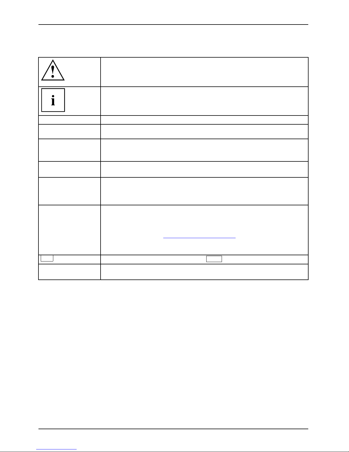
Notational conventions
Pay particular attention to text marked with this symbol. Failure to observe
this warning will endanger your life, will damage the device or lead to loss
of data. The warranty will be invalidated if you cause defects in the device
through failure to take n o tice of this warning
indicates important informat
ion that is required to use the device properly.
►
indicates an activity that must be performed in the order show n
indicates a result
This style
flags data entered using the keyboard in a program dialog or command
line, e.g. your password ( Name123) or a command to launch a program
(start.exe)
This style
refers to information displayed by a program on the screen, e.g.:
Installation is completed
This style
is for
• terms and texts in a softwar
e user interface, e.g.: Click Save.
• names of programs or files, e.g. Windows or setup.exe.
"This s tyle"
is for
• cross-references to another section, e.g. "Safety information"
• cross-references to an external source, e.g . a web address: For more
information, go to "
www.fujitsu-siemens.com"
• indicates names of CDs and DVDs as well as names and titles of other
materials, e.g.: "CD/D VD Drivers & Utilities" or "Safety" manual
Abc
refers to a key on the keyboard, e.g.:
F10
This style
flags concepts and text that are emphasised or highlighted, e.g.: Do not
switch off device
2 A26391-K230-Z120-1-7619, edition 2
Page 11

Important notes
Important notes
Take note of the safety hints provided in the "Safety" manual, in the "Professional
Notebook" operating manual and in this manual.
A26391-K230-Z120-1-7619, edition 2 3
Page 12

Ports and operating elements
Ports and operating elements
This chapter presents the individual hardware components. This will pro vide you with an
overview of the ports and operating elements on the notebook.
Please familiarise yourself w ith these components before you start working with y our notebook.
4 A26391-K230-Z120-1-7619, edition 2
Page 13

Ports and operating elements
ESPRIMO Mobile U9200
StatusindicatorsMicrophoneExpressCardslotMemorycardslotCameraON/OFFswitchTouch padTouchpadbuttonsHeadphoneportMicrophone portUSBportDCjack(DCIN)KensingtonLockOpticaldriveMonitorportLANportModemp ortHarddiskBatteryBatteryrelea se latchS-VideooutsocketEasyLaunchkey
26
2
1
1
4
6
7
5
8
9
10
11
12
3
13
15
16
17
18
19
20
21
22
22
23
24
27
25
14
1 = Microphone
2=Camera
3 = ON/OF F switch for radio components
4 = ON/OFF switch
5 = Touchpad buttons
6 = Touchpad
7 = Status indicators
8 = Headpho ne port
9 = Microphone port
10 = Memory card slot
11 = Modem port
12 = USB ports
13 = Optical drive
14 = ExpressCard slot for Expres
sCard/34
15 = LAN port
16 = Monitor port
17 = S-Video out socket
18 = DC jack (DC IN)
19 = Kensington Lock
20 = USB port
21 = Battery
22 = Battery release latch
23 = Service compartment (memory)
24 = Connector for second battery
(travel battery)
25 = Connection for port replicat
or
26 = Service compartment (hard disk)
27 = SIM card slot (concealed in t
he
battery compartment)
A26391-K230-Z120-1-7619, edition 2 5
Page 14

Ports and operating elements
ESPRIMO Mobile M9400
14
13
15
16
17
18
19
20
21
22
23
23
24
25
27
26
2
1
1
4
6
7
5
8
9
10
11
12
3
28
1 = Microphone
2 = Camera (optional)
3 = O N /OFF switc
h for radio compo nents
4 = ON/OFF switch
5 = Touchpad b
uttons
6 = Touchpad
7 = Status in
dicators
8 = Headphone port
9 = Micropho
ne port
10 = Memory card slot
11 = Expres
sCard slot for ExpressCard /34
and Exp
ressCard/54
12 = USB ports
13 = USB po
rt
14 = Optical drive
15 = Mode
m port
16 = DC jack (DC IN)
17 = Kensington Lock
18 = LAN port
19 = USB port
20 = Monitor po
rt
21 = S-Video out socket
22 = Battery
23 = Battery release latch
24 = Service c
ompartment (memory)
25 = Connector for second battery
(travel battery)
26 = Connec
tion for port replicator
27 = Service compartment (hard disk)
28 = SIM ca
rd slot (concealed in the
batte
ry compartment)
6 A26391-K230-Z120-1-7619, edition 2
Page 15

Ports and operating elements
ESPRIMO Mobile D9500
1
5
4
3
2
6
7
8
10
9
11
12
13
18
19
16
17
15
14
20
21
21
22
23
25
24
26
1 = Microphone
2 = ON/OF F switch for radio components
3 = ON/OFF switc
h
4 = Touchpad buttons
5 = Touchpad
6 = Status indicators
7 = Headpho n
e port
8 = Microphone port
9=Memoryca
rd slot
10 = ExpressCard slot for ExpressCard/34
and ExpressCard/54
11 = Optica
ldrive
12 = Modem port
13 = USB po
rts
14 = LAN port
15 = Monitor port
16 = S-Video out socket
17 = USB port
18 = DC jack (DC IN)
19 = Kensingto
n Lock
20 = Battery
21 = Battery r
elease latch
22 = Service compartment (memory)
23 = Connecto
r for secon d battery
(travel
battery)
24 = Connection for port replicator
25 = Servic
e compartment (hard disk)
26 = SIM card slot (concealed in the
battery compartment)
A26391-K230-Z120-1-7619, edition 2 7
Page 16

Ports and operating elements
Switching on the notebook
2
1
► On devices with a release button: Slide the
release button in direction of the arrow (1).
► Lift up the LCD screen (2).
1
► Press the ON/OFF switch (1) for around 1
second to switch the notebook on.
The power-on indicat
or lights up.
Windows XP
You ca n con figure the power button with Start - (Settings) - Control Panel Performance and Maintenance - Power Options - Advanced.
Windows Vista
You ca n c on figure the power butto n with Start - (Settings) - Control
Panel - Mobile PC - Power Option s .
If you have assigned a password, you must enter this when requested to do so, in order
to start the operating system. Further information can be found in the "Professional
Notebook" operating manual, section entitled "Security f unct ions".
8 A26391-K230-Z120-1-7619, edition 2
Page 17

Ports and operating elements
Switching off the Notebook
► Close all applications and shut down your operating system (please
see operating system manual).
If the notebook cannot be shut down prope rly, press and hold the ON/OFF button for
approximately four seconds. The notebook will switch off. Any unsaved data may be lost.
► Close the LCD screen.
A26391-K230-Z120-1-7619, edition 2 9
Page 18

Ports and operating elements
Status indicators
Statusindicators
The status indicators provide information about the status of the power supply,
the drives and the keyboard functions.
A 1
Power-on indicator
Scroll Lock indicator
Battery charging indicator Num Lock indicator
Hard disk indicator Radio components indicator
Caps Lock indicat
or
10 A26391-K230-Z120-1-7619, edition 2
Page 19

Ports and operating elements
The meanings of the symbols are as follows:
Power-on indicator
• Indicator is lit up: The notebook is switched on and ready to use.
• Indicator flashes: The notebook is in standby mode.
• The indicator is not lit up: The notebook is switched off.
Battery charging indicator
Indicator lights up: the battery is charging.
BatteryindicatorBatterysymbolBatterychargingindicator
Drive indicator
Indicator lights up: one of the drives (e.g. hard disk, CD/DVD) is being accessed.
DriveindicatorIndicator
Caps Lock indicator
Indicator lights up: the Caps Lock key has
been pressed.
All the characters you type appear in uppe
r case. In the case of overlay keys, the
character printed on the upper left of t
he key appears when that key is pressed.
CapsLockindicatorCapsLock
Scroll Lock indicator
Indicator lights up: the key combination
Fn
+
Scroll Lock
has been pressed.
The effect this key has varies from programme to programme.
ScrollLock:ScrollLockindicatorScroll
Num Lock indicator
Indicator lights up: the key comb ination
Fn
+
Num
has been pressed.
The numeric keypad is activated. In the case of overlay keys, the character printed
on the upper right of the key appears when that key is pressed.
NumLockNumLockindicator
Radio components indicator
Indicator is illuminated: The radio components EasyLaunch key has been pressed.
One or more radio components are switched on.
Radiocompon
entsindicator
A26391-K230-Z120-1-7619, edition 2 11
Page 20

Ports and operating elements
Key combinations
The key combinations described below apply when using Microsoft Windows
operating systems. Some of the following key combinations may not function in
other operating systems and with some device drivers.
Key combinations are entered as follows:
► Press and hold the first key in the combination.
► W hile holding the first key down, press the other key or keys in the combination.
The key combination
Ctrl
+
Alt Gr
or
Ctrl
+
Alt
canbeusedon
external keyboards that do not not feature a
Fn
key.
Switching the radio components on/off
BluetoothBluetoothWLANWLANFn+F1
Use this key combination to start WirelessSelector. Th e radio components that
have been activated in BIOS Setup can be switched on and off individually.
If the WirelessSelector program is n ot installed on your device, all of the radio components
activated in the BIOS Setup can only be switched on and off together with
Fn
+
F1
.
Switch loudspeakers ON/OFF
Fn+F3Loudspeaker
This key combination switches your notebook’s loudspeakers off and on.
Decrease volume
Fn+F4Volume
This key combination reduces th e volume of the integrated loudspeakers.
Increases volume
Fn+F5Volume
This key combination increases the volume of the integrated loudspeakers.
Switch touchpad ON/OFF
This key combination switches your notebook’s touchpad off an d on.
Fn+F6TouchpadTouchpa
d
Switch camera ON/OFF (depending on your device)
Use this key combination to switch the notebook’s integrated camera on or off.
Fn+F7CameraCamer
a
Decrease screen brightness
Fn+F8Screenbr ightness
This key combination decreases the brightness of the screen.
12 A26391-K230-Z120-1-7619, edition 2
Page 21

Ports and operating elements
Increase screen brightness
Fn+F9Screenbr ightness
This key combination increases the brightness of the screen.
Toggle output screen
Fn+F10Toggleoutputscreen
Use this key combination to select which screen(s) is/are used for display
if an external monitor is connected.
You can opt to use:
• just the notebook’s LCD screen
• just the e xternal monitor
• both the LCD screen and the external monitor
Sleep mode
ActivateenergysavingmodeFn+F12Sleepmode
Use this key combination to activate the currently configured energy saving
mode.
Switching b etween open applications
Use this key combination to switch between several open applicat ions.
Alt+Tab
AltCtrl
Del
++
Performwarmreboot
This key combination restarts th
e notebook. First, press and hold
both the
Ctrl
and
Alt
keys, then press th
e
Del
key. First, the
Task Manager will be displayed
. You must then press all three keys
again to reboot.
Ctrl+Alt+DelWarmreboot
Back tab
This key combination moves the cu
rsor back to the previous tabular
stop.
Shift+TabBacktab
Key combinations using the Windows keys are detailed in the manual
for your operating system.
A26391-K230-Z120-1-7619, edition 2 13
Page 22

Ports and operating elements
Camera (depending on notebook m odel)
Your device is fitted with a VGA camera (1), which can also be used as a w ebcam.
1
14 A26391-K230-Z120-1-7619, edition 2
Page 23

Ports and operating elements
Removing and installing the bat
tery
NotesBattery
Only use batteries approve d by Fujitsu Siemens Computers for your notebook.
Never use force when inserting or removing a battery.
Make sure that no foreign bodies get into the battery connections.
The illustrations shown below may differ f rom your actual device. They are
merely intended to clarify the principles involved.
Removing the battery
► Switch the notebook off and pull the power plug out of the mains socket.
Battery
► Close the LCD screen.
► Disconnect all cables connected to the notebook.
► Turn your notebook over and place it
on a stable, sturdy, flat surface. If necessary, lay an
anti-slip cloth on this surface to
prevent the notebook from being scratched.
1
2
3
► Pus h the battery lock in the direction of
the arrow (1) a s far as it will go .
► Slide the locking device in the dir
ection of
the arrow (2) and hold it in place.
► Remove the battery from the notebook
in the direction of the arrow (3).
Inserting the battery
1
2
1
► Place the battery in the battery compartment
so that the contacts enter first (1).
Battery
► Pus h the battery into the battery
compartment until you feel it click into place.
► Pus h the battery lock in the direction of
the arrow (2) up to the stop.
A26391-K230-Z120-1-7619, edition 2 15
Page 24

Ports and operating elements
Removing/fitting the second battery/travel
battery (optional)
NotesTravel battery
Only use batteries approved by Fujitsu Siemens Computers for your notebook.
Never use force when fitting or removing a battery.
Make sure that no foreign bodies get into the battery connections.
It is possible to fit a second battery/travel battery to your device. The underside of
the device features a connector for this purpose.
The illustrations shown below may differ from your actual device. They are
merely intended to clarify the principles involved.
Installing the battery
► Switch off your notebook and disconnect the power plug from the mains socket.
Battery
► Close the LCD screen.
► Disconnect all cables connected to the notebook.
► Turn your notebook over and place
it on a stable, flat and clean surface. If necessary, lay
a non-slip cloth on this surface t
o prevent the notebook from being scratched.
1
► Slide the cover for t
he battery connector in the direction of the arrow (1).
16 A26391-K230-Z120-1-7619, edition 2
Page 25

Ports and operating elements
1
a
a
b
► First, locate the battery in the two slots (a).
► Fold the battery down into the battery connector in the direction of the
arrow (1) until it locks into place.
1 1
► Unfold th
e tilting device (1) on the battery, if present.
A26391-K230-Z120-1-7619, edition 2 17
Page 26

Ports and operating elements
Removing the battery
► Switch off your notebook and disconnect the power plug from the mains socket.
Battery
► Close the LCD screen.
► Disconnect all cables connected to the notebook.
► Turn your notebook over and place it on a stable, flat and c lean surface. If necessary, lay
a non-slip cloth on this surface to prevent the notebook from being scratched.
► F old in the tilting device on the battery, if present.
1
1
2
► Raise the battery at the rear corners (1) and lift out of the notebook from the front (2).
18 A26391-K230-Z120-1-7619, edition 2
Page 27

Ports and operating elements
1
► Slide the cover for the battery connector in the direction of the arrow (1).
A26391-K230-Z120-1-7619, edition 2 19
Page 28

Ports and operating elements
SIM card
Follow the instructions supplied by the provider of the SIM card.
The SIM card slot is located in the battery compartm ent. It can only
be accessed by taking out the battery.
Inserting the SIM card
► Switch the notebook off and pull the power plug out of the mains socket.
► Close the LCD screen.
► Disconnect all cables connected to the notebook.
► Turn your notebook over and place it on a stable, flat and c lean surface. If necessary, lay
an anti-slip cloth on this surface to prevent the notebook from being scratched.
► Remove the battery (see Section "
Removing the battery", Page 15).
1
► Insert the SIM card into the slot so that
the chip is facing downwards and the
angled corner is at the front left, facing
towards the slot (1). Ensure that you hear
the SIM card click into place.
► Reinstall the battery (
see "
Inserting the battery", Page 15).
► Turn the notebook the right way up and place it on a flat surface.
► Reconnect the cables that
you disconnected previously.
20 A26391-K230-Z120-1-7619, edition 2
Page 29

Ports and operating elements
Removing the SIM card
► Switch the notebook off and pull the power plug out of the mains socket.
► Close the LCD screen so that it locks into place.
► Disconnect all cables connected to the notebook.
► Turn your notebook ove r and place it on a stable, flat and clean surface. If necessary, lay
an anti-slip cloth on this surface to prevent the notebo ok from being scratched.
► Remove the battery (see Section "
Removing the battery", Page 15).
2
1
► Pus h the SIM card inwards slightly to
eject it from the slot (1).
► Pull the SIM card out of the slot in the
direction of the arrow (2).
► Reinstall the battery (see "
Inserting the battery", Page 15).
► Turn the notebook the right way up and place it on a flat surface.
► Reconnect the cables that you disconnected previously.
A26391-K230-Z120-1-7619, edition 2 21
Page 30

Ports and operating elements
Radio com ponents: Wireless LAN/Bluetooth/UMTS
WirelessLANBluetoothUMTS
The installation of a wireless LAN module not approved by Fujitsu
Siemens Computers GmbH voids the permits issued for this device
(see chapter "
Technical data", Page 30).
Switching the radio components
on and off
Start the WirelessSelector using the radio components EasyLaunch key or
the key combination
Fn
+
F1
.
The WirelessSelector allows the radio components activated in BIOS Setup to
be switched on and off individually.
WirelessLANWirelessLANBluetoothBluetoothUMTSUMTS
► Press the EasyLaunch button to start
the WirelessSelector.
or
► Press the key combination
Fn
+
F1
to start the WirelessSelector.
The radio component indicator will be
illuminated when one or more radio
components is switched on.
If you switch off the radio components, the Bluetooth module, UMTS and wireless
LAN transmission unit (antenna) will also be switched off.
You can enable or disable the radio components individually.
BIOS Setup allows you to specify which radio components can be switched on and off
using the EasyLaunch key or the key com bination
Fn
+
F1
. Only those components
that have been activated in BIOS Setup can be switched on and off using the EasyLaunch
key or the key combination
F
n
+
F1
. C onversely, components that are deactivated in
BIOS setup cannot be controlled using the EasyLaunch key o r the key combination.
You can also activate and deactiva te the radio components individually in the BIOS Setup.
Pay attention to the additional safety notes for devices with radio
components provided in the "Safety" manual.
Details on using Wireless LAN can be found in the online help system
included in the Wireless LAN software.
More detailed information on how to use Bluetooth can be found on
the "Drivers & Utilities" CD/DVD.
You can obtain more information on UMTS from your service provider.
22 A26391-K230-Z120-1-7619, edition 2
Page 31

Removing and installing components
during servicing
Removing and installing compo
nents
during servicing
Only qualified technicians should repair your notebook. Unauthorised
opening or incorrect repair may greatly endanger the user (electric shock,
fire risk) and will invalidate your warranty.
Components
Servicing
You may remove and install the components described in this chapter yourself
after consulting the Hotline/Help Desk.
If you remove and install components without consulting the Hotline/Help
Desk, t hen the warranty of your notebook will be voided.
The illustrations shown below may differ f rom your actual device. They are
merely intended to clarify the principles involved.
Notes on installing and rem oving boards
and components
• Switch the notebook off and pull the power plug out of the mains socket.
• Remove the battery.
• Take care when you use the locking mechanisms on the battery and any other component.
• Never use sharp objects su
ch as screwdrivers, scissors or knives as leverage to remove covers.
NotesBoardESD
Boards with electrostatic sensitive devices (ESD) are marked with the label
shown.
When handling boards fitted with ESDs, you must always observe the following
points:
• You must always discharge static build up (e.g. by touching a grounded
object) before working.
• The equipment and tools you use must be free of static charges.
• Remove the power plug from the mains supply before inserting or removing
boards containing ESDs.
• Always hold boards with ESDs by their edges.
• Never touch pins or conductors on boards fitted with ESDs.
A26391-K230-Z120-1-7619, edition 2 23
Page 32

Removing and installing components
during servicing
Hard disk
The hard disk is the most important storage medium of your notebook. You can work considerably
faster and more efficiently if you copy applications and files from CDs to your hard disk.
When the hard disk is accessed, the hard disk indicator lights up in the status indicator panel.
Removing the hard disk
► Switch the notebook off and pull the power plug out of the mains socket.
Harddisk
► Close the LCD screen.
► Disconnect all cables connected to the notebook.
► Turn your notebook over and place it on a stable, sturdy, flat surface. If necessary, lay an
anti-slip cloth on this surface to prevent the notebook from being scratched.
► Remove the battery (see "
Removing the battery", Page 15).
1
► Remove the screw (1).
► Lift off the hard disk cover.
1
► Use the pulling aid to pull the hard disk out
of the bay in the direction of the arrow (1).
24 A26391-K230-Z120-1-7619, edition 2
Page 33

Removing and installing components
during servicing
Installing the hard disk
1
► Insert the hard disk into the hard
disk compartment in the direction
of the arrow (1) .
1
► Place the hard disk cove
r over the opening.
► Tighten the screw (1).
► Install the battery again (see "
Inserting the battery", Page 15).
► Turn the notebook the right way up and place it on a flat surface.
► Reconnect the cables that you disconnected previously.
A26391-K230-Z120-1-7619, edition 2 25
Page 34

Removing and installing components
during servicing
Removing and installing memory
modules
MainmemoryMemoryexpansionMemoryupgradeSystemexpansion
Your notebook supports dual-channel DDR2 technology.
The dual-channel DDR2 technology can only be used with two identical memory
modules. When two different memory modules are installed, only "single-channel"
mode is supported. This reduces the performance of your notebook.
With a memory configuration of 4 GBytes, the visible and usable main memory
may be reduced to 3 GByte s (depending on the operating system).
If you are asked by the Hotline/Help Desk to remove and install the memory
modules yourself, proceed as follows:
Pay attention to the relevant safety notes provided in the "Important notes" chapter.
The notebook must be switched off when installing/removing the memory
modules, it must not be in Suspend mode.
Only use approved memory expansion modules in your notebook
(see Section "
Technical data", Page 30).
Never use force when installing o r removing memory modules.
Make sure that foreign objects do not fall into the memory expansion compartment.
Individual components (e.g. the
processor heat sink) can become very hot
during operation. Therefore,
we recommen d that you wait one hour after
switching off the notebook bef
ore removing or installing the memory modules.
Otherwise, there is a risk of su
ffering burns!
As some non-ESD safe compo nent
s are exposed, please observe the section "
Notes
on installing and removing boa
rds and component s", Page 23.
► Switch your notebook off and unplug the mains adapter from the m ains outlet.
► Close the LCD screen.
► Disconnect all cables connected to the notebook.
► Turn your notebook over and place it on a stable, flat and c lean surface. If necessary, lay
an anti-slip cloth on this surface to prevent the notebook from being scratched.
► Remove the battery (see "
Removing the battery", Page 15).
26 A26391-K230-Z120-1-7619, edition 2
Page 35

Removing and installing components
during servicing
Removing the cover
1
2
► R e move the screw (1).
► Pull the cover off the notebook (2).
Removing memory modules
3
2
1
1
► Carefully push the tw
o mounting
clips outwards (1).
MemoryexpansionMemorymodule
The memory module snaps upwards (2).
► Pull the memory m odule ou
tofitsslot
in the direction of the ar
row (3).
Installing a memory module
2
a
1
► Insert the memory module with the contacts
and the recess (a) facing the slot (1).
MemoryexpansionMemorymodule
► Carefully push the memory module
downwards until you feel it click
into place (2).
A26391-K230-Z120-1-7619, edition 2 27
Page 36

Removing and installing components
during servicing
Attaching the cover
2
1
1
► Place the cover in the correct
mounting position (1).
► Fasten the cover with the screw (2).
► Reinstall the battery (see "
Inserting the battery", Page 15).
► Turn th e notebook the ri
ght way up and place it on a flat surface.
► R econnect the cables that you disconnected previously.
28 A26391-K230-Z120-1-7619, edition 2
Page 37

Removing and installing components
during servicing
Removing and installing the opt
ical drive
If you are asked by the Hotline/Help Desk to remove and install the optical
drive yourself, proceed as follows:
Removing the optical drive
► Switch off your notebook and disconnect the power plug from the mains socket.
► Close the LCD screen.
► Disconnect all cables connected to the notebook.
► Turn your notebook over and place it on a flat surface.
► Remove the battery (see Chapter "
Removing the battery", Page 15).
Harddisk
2
1
► R e move the screw (1).
► Press a metal pin or wire (e.g. paperclip)
firmly into the o pening (2).
The drive tray will be ejected. You can now
pull out the drive tray completely.
► Hold the drive tray firmly on both sides in the centre, and carefully pull
the op tical drive out of the notebook.
► Push in the drive tray until you feel it lock into place.
Installing the optical drive
1
1
► Slide the drive into the notebook in the
direction of the arrow (1).
► Tighten the screw (2).
► Reinstall the battery (see "
Inserting the battery", Page 15).
► Turn the notebook the right way up and place it on a flat surface.
► Reconnect the cables that you disconnected previously.
A26391-K230-Z120-1-7619, edition 2 29
Page 38

Technical data
Technical data
Notebook
Technicaldata
Environmental conditions
Environmental class 3K2
Temperature
Operating (3K2) 5 °C – 35 °C
Transportation (2K2) -15 °C – 60 °C
Dimensions
Width x Depth x Height (front/back) • ESPRIMO Mobile U9200:
300 mm x 223 mm x 37.5 mm
• ESPRIMO Mobile M9400:
335 mm x 245 mm x 38 mm
• ESPRIMO Mobile D9500:
360 mm x 260 mm x 37.5 mm
Weight (depending on configuration) • ESPRIMO Mobile U9200: Approx. 1.9 kg
• ESPRIMO Mobile M9400: Approx. 2.2 kg
• ESPRIMO Mobile D9500: Approx. 2.5 kg
The data sheet for this notebook contains further technical data. The data sheet
can be found on your notebook or on the Internet at "
www.fujitsu-siemens.com"
or on the "Drivers & Utilities" CD/DVD.
Battery
Techn ical d
ata
Main battery Second battery/travel battery
Rated voltage 11.1 V 11.1 V
Rated capacity 5200 mAh 3800 mAh
The operating time depends on the device equipment, the active
applications and the energy saving settings.
Mains adapter
Techn
icaldataforthe
Electrical data
Rated voltage 20 V
Max. rated current 4.5 A
An additional mains adapter and power cable can be ordered at any time.
30 A26391-K230-Z120-1-7619, edition 2
Page 39

Index
Index
A
Activate energy saving mode 13
Alt+Tab 13
B
Back tab 13
Battery 5
important notes 15
inserting 15
removing 15–16, 18
Battery charging indicator 11
Battery indicator
see battery indicator 11
Battery release latch 5
Battery symbol
see battery indicator 11
Bluetooth 22
switching off 12, 22
switching on 12, 22
Board 23
C
Camera 5
switching off 12
switching on 1 2
Caps Lock
indicator 11
Caps Lock indicator 11
Components
installing / removing 23
Ctrl+Alt+Del 13
D
DC jack (DC IN) 5
Drive indicator 11
E
EasyLaunch key 5
ESD 23
ExpressCard s lot 5
F
Fn + F1 12
Fn + F10 13
Fn + F12 13
Fn + F3 12
Fn + F4 12
Fn + F5 12
Fn + F6 12
Fn + F7 12
Fn + F8 12
Fn + F9 13
H
Hard disk 5
removing 24, 29
Headphone port 5
I
Indicator
Drive 11
K
Kensington Lock 5
L
LAN port 5
Loudspeaker
switching ON/OFF 12
M
Main memory 26
Memory card slot 5
Memory expansion 26
installing 27
removing 27
Memory module
installing 27
removing 27
Memory upgrade 26
Microphone 5
Microphone port 5
Modem port 5
Monitor port 5
N
Notes
battery 15
boards 23
travel battery 16
Num L ock
indicator 11
Num Lock indicator 11
A26391-K230-Z120-1-7619, edition 2 31
Page 40

Index
O
ON/OFF switch 5
Optical drive 5
R
Radio components indicator 11
S
S-Video out socket 5
Screen brightness
decrease 12
increase 13
Scroll
indicator 11
Scroll Lock indicator 11
Scroll Lock:
indicator 11
Servicing 23
Shift+Tab 13
Sleep mode
activating 13
Status indicators 5, 10
System expansion
memory expansion 26
T
Technical data
battery 30
Notebook 30
Technical data for the
mains a dapter 30
Toggle output screen 13
Touchpad 5
switching off 12
switching on 12
Touchpad buttons 5
Travel battery
important not es 16
U
UMTS 22
switching off 22
switching on 22
USB port 5
V
Volume
decrease 12
increase 12
W
Warm reboot 13
Wireless LAN 22
switching off 22
switching on 22
WLAN
switching off 12
switching on 12
32 A26391-K230-Z120-1-7619, edition 2
 Loading...