

Page 1

Mainboard Deutsch, English, Français
Short Description
Mainboard D2470
Page 2

Sie haben...
technische Fragen oder Probleme?
Wenden Sie sich bitte an:
• Ihren zuständigen Vertriebspartner oder Ihre Verkaufsstelle
• unsere Hotline über das Kont aktfo rmular unter
"www.fujitsu-siemens.com/support/contact/contact.html" oder für
Kunden, die ein einzelnes Mainboard gekauft haben: +49(0) 180 3777 005
Aktuelle Informationen zu unseren Produkten, Tipps, Updates usw. finden Sie im
Internet: "www.fujitsu-siemens.com/mainboards"
Are there...
...any technical problems or other questions you need clarified?
Please contact:
• your sales partner or your sales outlet
• our hotline for customers who have purchased the mainboard as a single
delivery unit: +49(0) 180 3777 005
The latest information and updates (e.g. BIOS update) on our mainboards can be
found on the Internet at: "www.fujitsu-siemens.com/mainboards"
Page 3

Copyright © Fujitsu Siemens Computers GmbH 2006
Intel, Pentium and Celeron are registered trademarks of Intel Corporation, USA.
Microsoft, MS, MS-Dos and Windows are registered trademarks of Microsoft Corporation.
PS/2 and O S /2 Warp are registered trademarks of International Business machines, Inc.
All other trademarks referenced are trademarks of their respective owners, whose
protected rights are acknowledged.
All rights, including rights of tran slation, reproduction by printing, copying or similar
methodas, even of parts are reserved.
Offenders will be liable for damages.
All rights, including rights created by patent grant or registration of a utility model or
design, are reserved. Delivery sub ject to availability.
Right of technical modification reserved.
Page 4

Dieses Handbuch wurde erstellt von/This manuel was produced by Xerox Global Services
Herausgegeben von/Published by
Fujitsu Siemens Computers GmbH
AG 10/06
Ausgabe/Edition1
Page 5
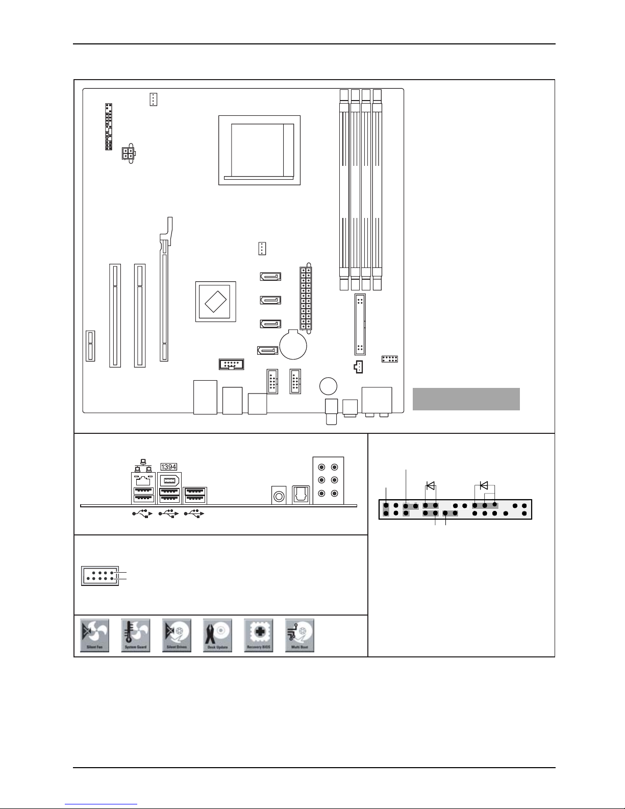
Internal connectors and slots
Optionale Komponenten /
Optional components
External connectors rear
USB dual channel
1
2
1 = VCC C
2 = VCC D
S/PDIF S/PDIF opt.
3 = Data negative C
4 = Data negative D
5 =
6 = Data positive D
Data positive C
7 = GND
8 = GND
9 = Key
10 = Not connected
PCI e x16
Power supply
Floppy drive
PCI Slot 2
PCI Slot 1
PCI e x1
Firewire
USB
SPDIF
Buzzer
Audio
USB
SATA 1
SATA 2
SATA 3
SATA 4
Fan 2
CPU Power supply
Frontpanel
Fan 1
Battery
Front panel
1) Both connector positions possible
2) 2pin or 3pin connector possible
Recovery inserted = The system starts
from floppy and allows a BIOS recovery
Password inserted = System- and BIOS
Password are skipped when device is
switched on
Channel A Slot 1
Channel B Slot 2
Channel A Slot 3
Channel B Slot 4
1
2
HD-LED
Power On/Off
Recovery Password
1)
Reset
Power On LED
2)
Ausgabe 1 1
Page 6
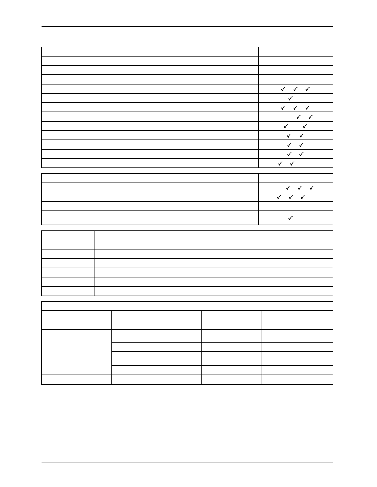
Internal connectors and slots
Features D2470-A
Chipset
nVIDIA / MCP55S
Board size
μBTX
VGA
-
Audio / 8-channel /S/PDIF / /
Buzzer / int. Speaker Support
/LAN 1 Gbit / 100 Mbi / 10 Mbit / /
LAN ASF /Aol / WoL / Boot - / - / /
SATA / ATA / RAID /-/
FireWireTM/USB2.0 /
FAN monitored PSU* / CPU / AUX1 / AUX2 - / / /FAN controlled PSU* / CPU / AUX1 / AUX2 - / / /TEMP monitored CPU / ONB1 / ONB2 / OFFB / /-/-
Special Features
D2470-A
Silent Fan / Silent Fan LT / System Guard / Silent Drives
-/
/ /
Recovery BIOS / Desk Up date / Multi Boot / Safe Standby
/ / /-
HDD Password
-
Logo Boot / Intel On Screen Branding
/-
Silent Fan LT
Independent temperature related processor and fan supervision and contro l
System Guard View and adjust Silent Fan LT
Silent Drives
Noise reduction for optical and hard disk drives
Recovery BIOS
Restores a corrupted BIOS
Desk Update Simple driver update with DU CD
Multi Boot
Comfortable boot from any boot device
HDD Passwort
Access protection for ATA5/ATAI5 disk drives
Power Supply Requirements - for onboard components (worst case)
Source
Voltage
Maximal variation
Mainboard current
Maximal*
+12V
+/–5%
12 A
–12V
+ / – 10%
0.05 A
+5V +/–5% 6.0A
Main Power Supply
+3.3V
+/–5%
1.0 A
Aux. Power Supply
+5V
+/–5%
2.0 A
* maximal mainboard current without PCI, PCIexpress and USB load
2 Ausgabe 1
Page 7
Kurzbeschreibung des Mainboard
Kurzbeschreibung des Mainboa
rd
Hinweise zu den Baugruppen
Beachten Sie bei Baugruppen mit EGB unbedingt Folgendes:
• Sie müssen sich statisch entladen (z. B. durch Berühren eines geerdeten
Gegenstands), bevor Sie mit Baugruppen arbeiten.
• Verwendete Geräte und Werkzeuge müssen frei von statischer Aufladung sein.
• Ziehen Sie den Netzstecker, bevor Sie Baugruppen stecken oder ziehen.
• Fassen Sie die Baugruppen nur am Rand an.
• Berühren Sie keine Anschluss-Stifte oder Leiterbahnen auf der Baugruppe.
Eine Übersicht der Leistungsmerkmale finden Sie im Datenblatt.
Besondere Merkmale
Ihr Mainboard ist in verschiedenen Ausbaustufen erhältlich. Abhängig von der Konfiguration
Ihres Mainboards besitzt oder unterstützt das Mainboard bestimmte Merkmale.
In diesem Handbuch finden Sie die wichtigsten Eigenschaften dieses Mainboards beschrieben.
Anschlüsse und Steckverbinder
Die Position der Anschlüsse und Steckverbinder Ihres Mainboards finden
Sie am Anfang des Handbuchs.
Die markierten Komponenten und Steckverbinder müssen nicht auf
dem Mainboard vorhanden sein.
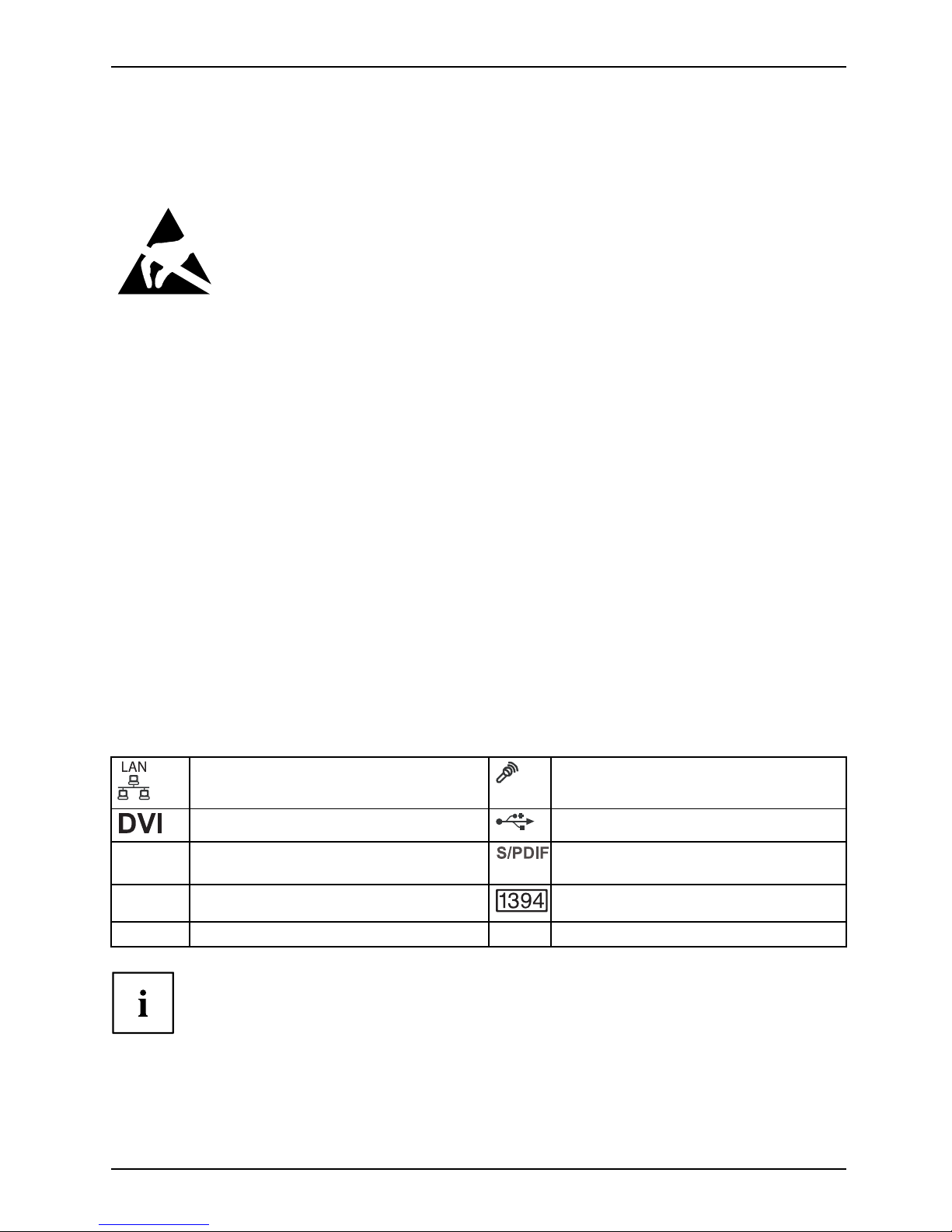
Externe Anschlüsse
Die Position der externen Anschlüsse Ihres Mainboards finden Sie am Anfang des Handbuchs.
LAN-Anschluss (RJ-45) Mikrofonanschluss, rosa
DVI-Anschluss
USB – Universal Serial Bus, schwarz
Rear Center / LF E , orange
Digitaler 6-Kanal Audioau
sgang,
orange
Rear Surround-side, grau
FireWireTM,grau
Rear Surround, schwarz
Die externen USB-Ansch
lüsse auf der Rückseite dürfen einzeln bis
max. 0.5 A belastet werd
en.
Ausgabe 1 3
Page 8

Kurzbeschreibung des Mainboard
Prozessor ein-/ausbauen oder tauschen
(mit Kühlkörper)
Für alle hier beschriebenen Arbeiten muss Ihr System vollständig von der Netzspannung
getrennt sein! Nähere Angaben dazu finden Sie in der Betriebsanleitung Ihres Systems.
Technische Daten
• AMD Athlon 64, Athlon 64 X2 und AMD Sempron mit bis zu 1 GHz Front Side
Bus (Hypertransport) in der Bauform AM2 (mPGA 940)
• Eine aktuelle Liste der von diesem Mainboard unterstützten Prozessoren finden Sie
im Internet unter: "www.fujitsu-siemens.com/mainboards".
Vorgehensweise
3
2
1
A
4
5
► Entfernen Sie ei
nen eventu ell vorhandenen Lüfter und den Küh lkörp er.
► Drücken Sie den Hebel in Pfeilrichtung (1) und schwenken Sie ihn bis zum Anschlag nach oben (2).
► Klappen Sie die Ha
lterung nach oben.
► Heben Sie den alten Prozessor aus dem Steckplatz (3).
Die abgeschrägte Ecke des Prozessors kann auch an einer anderen
Stelle sein als in der Abbildung dargestellt.
► Stecken Sie den neuen Prozessor so in den Steckplatz, dass die abgeschrägte Ecke des
Prozessors mit der Codierung am Steckplatz ( A) von der Lage her übereinstimmt (4).
4 Ausgabe 1
Page 9

Kurzbeschreibung des Mainboard
► Schwenken Sie den Hebel nach unten, bis er spürbar einrastet (5).
Bitte beachten Sie, dass je nach verwendetem Kühlkörper unterschiedliche
Kühlkörperhalterungen auf dem Mainboard benötigt werden.
► Je nach Ausbau-Variante müssen Sie eine Schutzfolie vom Kühlkörper abziehen oder den
Kühlkörper mit Wärmeleitpaste bestreichen, bevor Sie ihn aufsetzen.
► Je nach Prozessor-Variante werden für die Befestigung des Kühlkörpers noch
Klammern mitgeliefert, die den Kühlkörper fixieren.
Hauptspeicher ein-/ausbauen
Technische Daten
Technologie
DDR2 400 / DDR2 533 / DD R2 667 / DDR2 800 ungepufferte DIMM
Module 240-Pin; 1,8 V; 64 Bit, ohne ECC
Gesamtgröße 64 MBytes bis 8 GByte
Modulgröße
64, 128, 256, 512, 1024 oder 2048 MByte pro Modul
Eine aktuelle Liste der für dieses Mainboard empfohlenen Speichermodule finden Sie
im Internet unter: "www.fujitsu-siemens.com/mainboards".
Es muss mindestens ein Speichermodul eingebaut sein. Speichermodule mit unterschiedlicher
Speicherkapazität können komb iniert werden.
Es dürfen nur ungepufferte 1,8 V-Speichermodule ohne ECC verwendet werden.
DDR2-Speichermodule müssen der PC2-3200U- oder PC2-4200U- oder
PC2-5300U- oder PC2-6400U-Spezi fikation entsprechen.
Wenn Sie mehr als ein Speichermodul verwenden, dann achten Sie darauf,
die Speichermodule auf beide Speicherkanäle aufzuteilen. Dadurch nutzen
Sie die Performancevorteile des Dual-Channel-Mode.
Die maximale Systemperformance ist gegeben, wenn in Channel A und
Channel B identische Module verwendet werden.
Um die Bestückung zu erleichtern, sind die Steckplätze (Slots) farbig gekennzeichnet.
Wenn Sie die Speichermodule einstecken, beginnen Sie mit dem Steckplatz,
der am weitesten vom Prozesser entfernt ist (Slot 4).
Bei einer Speicherkonfiguration von 4GByte kann der sichtbare und benutzbare Hauptspeicher auf bis zu 3,5 GByte reduziert sein (abhängig von der Konfiguration des Systems).
Mehr als 4 GByte Hauptspeicher können nur mit entsprechendem
Betriebssystem genutzt werden.
Channel A
Channel B
Channel A
Channel B
1
2
3
4
Ausgabe 1 5
Page 10

Kurzbeschreibung des Mainboard
Anzahl der gesteckten Speichermodule
Zu verwendender Steckplatz 1 2 3 4
Channel A, Slot 1
x
Channel B, Slot 2
xx
Channel A, Slot 3
xxx
Channel B, Slot 4
xxxx
Multifunktionale Erweiterungskarten oder
Erweiterungskarten mit integrierter PCI-PCI Brigde
Diese Erweiterungskarten benötigen bis zu vier P CI-Interrupts: INT A, INT B, INT
C, INT D. Wie viele und welche dieser Interrupts verwendet werden, entnehmen
Sie der mitgelieferten Dokumentation d er Karte.
Die Zuordnung der PCI-Interrupts zu den IRQ Lines finden Sie in der folgenden Tabelle:
On board controller
PCI INT
LINE
1 2 3 4 5 6 7 8 9 10 11 12 13 14 15 16 17 18-22
IDSel
USB 1.1
1
th
---- - - - - - - - - -
x
--- - -
2
nd
---- - - - - - - - - -
x
--- - -
3
rd
---- - - - - - - - - -
x
--- - -
4
th
---x---- - -- - - ---- - -
USB 2.0
---- - - - - -
x
- - - ---- - -
SMBus
---- - - - -
x
-- - - ---- - -
Firewire
---x---- - -- - - ---- -
25
Azalia
-------- - -- - - ---
17
--
LAN
---- - - - - - - - - - - -
16
-- -
SATA 0
(native)
---- - - - - - - - -
13
---- - -
SATA 1
(native)
---- - - - - - - -
13
- ---- - -
Mechanical Slot
PCI INT
LINE
1234
5
6
7
8 9 10 11 12 13 14 15 16 17 18-22
IDSel
PCIe
x16, Slot 1
-- - -
DAB
C
--------- - -
x1,Slot4
-- - -
C
DA B
--------- - -
PCI
6 Ausgabe 1
Page 11

Kurzbeschreibung des Mainboard
PCI INT
LINE
1 2 3 4 5 6 7 8 9 10 11 12 13 14 15 16 17 18-22
IDSel
32, Slot 2
BA D
C
--------- ---- -
21
32, Slot 3
AB C D
--------- ---- -
23
Verwenden Sie zuerst PCI-/PCI-Express-Steckplätze, die über eine einzige PCI IRQ Line
verfügen (kein IRQ Sharing). Wenn Sie einen anderen PCI-/PCI-Express-Steckplatz mit IRQ
Sharing benu tzen müssen, überprüfen Sie, ob die Erweiterungskarte IRQ Sharing mit den
anderen Geräten auf dieser PCI IRQ Line einwandfrei unterstützt. Auch die Treiber aller K arte n
und Komponenten an dieser PCI IRQ Line müssen IRQ Sharing unterstützen.
BIOS-Update
Wann sollte ein BIOS-U
pdate durchgeführt werden?
Fujitsu Siemens Comput
ers stellt neue BIOS-Versionen zur Verfügung, um die Kompatibilität
zu neuen Betriebssyst
emen, zu neuer Software oder zu neuer Hardware zu gewährleisten.
Außerdem können neue B
IOS-Funktionen integriert werden.
Ein BIOS-Update sollt
e auch immer dann durchgeführt w erde n, wenn ein Problem besteht,
das sich durch neue Tre
iber oder neue Software nicht beheben lässt.
Wo gib t es BIOS-Update
s?
Im Internet unter "ww
w.fujitsu-siemens.com/mainboards" finden Sie die BIOS-Updates.
Ausgabe 1 7
Page 12

Short description of the mainboard
Short description of the mainb
oard
Information about the boards
Please make sure that you observe the following for boards with ESD:
• Always discharge any build up of static electricity (e.g. by touching a grounded
object) before working on the boards.
• The equipment and tools y ou use must be free of static charge .
• Disconnect the power plug from the mains supply before inserting or removing
boards.
• Always hold boa rds by their edges only.
• Never touch pins or conductor tracks on boards.
An overview of features is provided in the data sheet.
Special features
Your mainboard is available in different configuration levels. Depending on the configuration,
your mainboard is equipped with or supports certain features.
This manual describes the most important features of this mainboard.
Interfaces and connectors
The location of the interf
aces and connectors of your mainboard is specified
at the beginning of the man
ual.
The marked compon ents and
connectors are not n ecessarily present on the mainboard.
External connections
The location of the externa
l connections of your mainboard is specifie d at the beginning of the manual.
LAN port ( RJ-45)
Microphone jack, pink
DVI port
USB – Universal Serial Bus
,black
Rear centre / LFE, orange
Digital 6-channel audio output, orange
Rear surround - side, grey FireWireTM,grey
Rear surround, black
A maximum current of 0.5 A may be connected to the external
USB connections on the rear.
edition 1 8
Page 13

Short description of the mainboard
Installing/removing or replacing processor
(with heat sink)
Disconnect the system from the mains voltage before performing any of the tasks
described below. Details are contained in the operating m anual of your system.
Technical data
• AMD Athlon 64, Athlon 64 X2 and AMD Sempron with up to 1 GHz Front Side
Bus (Hypertransport) in AM2 design (mPGA 940)
• A current list of the processors supported by this mainboard is available on the
Internet at: "www.fujitsu-siemens.com/mainboards".
Procedure
3
2
1
A
4
5
► Remove the fan (if
present) and the heat sink.
► Pull the lever in t he direction of the arrow (1) and lift it as far as it will go (2).
► Fold up the frame.
► Remove the old processor from the slot (3).
The angled corner of the processor can also be located in a different
position than the one shown in the illustration.
► Insert the new pro
cessor in the socket so that the angled co rner of the p rocessor matches
thecodingonthes
ocket (A) with regard to the position (4).
9 edition 1
Page 14

Short description of the mainboard
► Push the lever back down until it clicks into place (5).
Please note that, depending on the heat sink used, different heat sink
mounts are required on the mainboard.
► Depending on the configuration variant, you must pull a protective foil off the heat sink
or coat the heat sink with heat conducting paste bef ore fitting it.
► Depending on the processor variant, clips may also be supplied for mounting
the heat sink that fixitinplace.
Removing/installing the main memory
Technical data
Technology
DDR2 400 / DDR2 53 3 / DDR2 667 / DDR2 800 unbuffered DIMM
modules 240-pin; 1.8 V; 64 bit, no ECC
Total s ize
64MBto8GB
Module size 64, 128, 256, 512, 1024 or 2048 MByte per module
A current list of the memory modules recommended for this mainboard is available on
the Internet at: "www.fujitsu-siemens.com/mainboards".
At least one memory module must be installed. Memory modules with different
memory capacities can be combined.
You may use only unbuffered 1.8 V memory modules w ithout ECC.
DDR2 memory modules must comply with the PC2-3200U / PC2-4200U
/ PC2-5300U / PC2-6400U specification.
If you use more than one m emory module, please d istribute the memory
modules across both memory channels. This will enable you to exploit the
performance advantages of the dual-channel mode.
The best possible system performance can be obtained by using identical
modules in Channel A and Channel B.
To simplify eq uipping, the slots are colour coded. When inserting the memory modules,
start from the slot which i s furthest away from the processor (slot 4).
With a memory configuration of 4 GB the visible and usable main memory may be
reduced down to 3.5 GB (depending on the system configuration).
More than 4 GB of main memory can only be used in conjunction with
a corresponding operating system.
Channel A
Channel B
Channel A
Channel B
1
2
3
4
edition 1 10
Page 15

Short description of the mainboard
Number of inserted memory modules
Slot to be used 1 2 3 4
Channel A, slot 1
x
Channel B, slot 2
xx
Channel A, slot 3
xxx
Channel B, slot 4
xxxx
Multifunctional expansion cards or expansion
cards with integrated PCI-PCI bridge
These expansion cards require up to four PCI interrupts: INT A , INT B, INT C, INT D. How many and
which of these interrupts are used is specified in the documentation provided with the card.
The assignment of the PCI interrupts to the IRQ Lines is shown in the following table:
On-board controller
PCI INT
LINE
123456
7
8 9 10 11 12 13 14 15 16 17 18-22 IDSel
USB 1.1
1
th
- - - - ---------
x
--- - -
2
nd
- - - - ---------
x
--- - -
3
rd
- - - - ---------
x
--- - -
4
th
---
x
--------- -- - - - -
USB 2.0
- - - - -----x------ - - -
SMBus
- - - - ----x------- - - -
Firewire
---
x
--------- -- - - -
25
Azalia
- - - - ----------- -
17
--
LAN
- - - - -----------
16
-- -
SATA 0
(native)
- - - - --------
13
-- - - - -
SATA 1
(native)
- - - - -------13---- - - -
Mechanical slot
PCI INT
LINE
123456
7
8 9 10 11 12 13 14 15 16 17 18-22 IDSel
PCIe
x16, Slot 1
----
DAB
C
---- - - - - - - -
x1, Slot 4
----
CDAB
---- - - - - - - -
PCI
32, Slot 2
BAD
C
----------- - - -
21
32, Slot 3 A B C D
----------- - - -
23
11 edition 4
Page 16

Short description of the mainboard
First use PCI/PCI Express slots that have a single PCI IRQ Line (no IRQ sharing). If you do
need to use another PCI/PCI Express slot with IRQ sharing, check whether the expansion card
properly supports IRQ sharing with the other devices on this PCI IRQ Line. The drivers of all
cards and components on this PCI IRQ Line must also support IRQ sharing.
BIOS update
When should a BIOS update be carried out?
Fujitsu Siemens Computers makes new BIOS versions available to ensure compatibility to new operating systems, new software or new hardware. In addition, new BIOS functions can also be integrated.
A BIOS update should always also be carried out when a problem exists that cannot
be solved with new drivers or new software.
Where can I obtain BIOS updates?
The BIOS updates are available on the Internet at "www.fujitsu-siemens.com/mainboards".
edition 1 12
Page 17

Brève description de la carte mère (M
ainboard)
Brève description de la carte m
ère
(Mainboard)
Remarques relatives aux cartes
Respectez impérativement les consignes suivantes avec les cartes équipées de
composants sensibles à l’électricité statique :
• Vous devez vous décharger de l’électricité statique (en touchant un ob jet relié à
la terre, par exemple) avant de manipuler les cartes.
• Les appareils et outils utilisés doivent être dépourvus de toute charge statique.
• Débranchez les câbles avant de connecter ou de déconnecter les c artes.
• Manipulez les cartes en les tenant uniquement par leurs bords.
• Evitez de toucher les broches ou les circuits d’une carte.
Vous trouverez un aperçu des caractéristiques de performances dans la fiche technique.
Caractéristiques
Votre carte mère est disponible en plusieurs niveaux d’équipement. Suivant sa configuration,
votre carte mère possède ou supporte certaines caractéristiques.
Vous trouverez dans ce manuel une description des principales caractéristiques de cette carte mère.
Ports et connecteurs
Vous trouverez au début du manuel la position des ports et des c onnecteurs sur votre carte mère.
Les composants et connecteurs marqués ne sont pas obligatoirement
disponibles sur la carte mère.
Ports externes
Vous trouverez au début du manuel la position des ports externes de votre carte mère.
Port LAN (RJ-45)
Port microphone, rose
Prise DVI
USB – Universal Serial Bus, noir
Rear Center / LF E , orange Sortie audio numérique 6 canaux,
orange
Rear Surround-side, gris
FireWireTM,gris
Rear Surround, noir
Chacun des ports USB externes au dos peut être chargé au maximum jusqu’à 0,5 A.
édition 1 13
Page 18

Brève description de la carte mère (M
ainboard)
Monter/démonter ou remplacer un processeur
(avec refroidisseur)
Avant de procéder aux étapes décrites ici, il est indispensable de séparer intégralement
votre système de la tension de secteur ! Vous trouverez à ce propos d’autres
indications détaillées dans le manuel de votre système.
Caractéristiques techniq
ues
• AMD Athlon 64, Athlon 64 X2 et AMD Sempron avec F ront Side Bus jusqu’à 1 GHz
(Hypertransport) dans la version AM2 (mPGA 940)
• Vous trouverez une liste ac
tualisée des processeurs supportés par cette carte mère sur
Internet à l’adresse suiva
nte : "www.fujitsu-siemens.com/mainboards".
Méthode
3
2
1
A
4
5
► Retirez le ventilateur éventuel ainsi que le refroidisseur.
► Soulevez le levier dans le sens de la flèche (1) et relevez-le jusqu’à la butée (2).
► Relevez le support vers le haut.
► Retirez l’ancien processeur de son logement (3).
L’angle bise auté du processeur peut également être situé à un autre
endroit que celui indiqué sur le dessin.
► Placez le nouveau processeur dans son logement de telle manière que le coin biseauté
du processeur coïncide (4) avec le codage sur le logement (A).
14 édition 1
Page 19

Brève description de la carte mère (M
ainboard)
► Rabaissez le levier vers le bas jusqu’à l’entendre s’encastrer (5).
Veuillez tenir compte du fait que les clips de fixation du refroidisseur nécessaires
sur la carte mè re varient en fonction du type de refroidisseur utilisé.
► Suivant le modèle, vous devez soit retirer un film de protection du refroidisseur soit enduire
le refroidisseur d’une pâte conductrice de chaleur avant de le monter.
► Des clips de fixation du refroidisseur sont compris dans la livraison suivan t le type de processeur.
Monter/démonter une mémoire centrale
Caractéristiques techniques
Technologie
Modules DIMM DDR2 400 / DDR2 533 / DDR2 667 / DDR2 800 sans
tampon 240 broches ; 1,8 V ; 64 bits, non-CCE
Taille totale
64 Mo jusqu’à 8 Go
Dimensions du module 64, 128, 256, 512, 1024 ou 2048 Moctets par module
Vous trouverez une liste actualisée des modules mémoire recommandés pour cette carte mère
sur Internet à l’adresse suivante : "www.fujitsu-siemens.com/mainboards".
Au moins un module d’extension mémoire doit être monté. Il est possible de combiner
des modules d’extension mémoire de capacités différentes.
Vous ne pouvez utiliser que des modules mémoire 1,8 V sans tampon non-CCE.
Les modules mémoire DDR2 doivent être conformes à la spécification
PC2-3200U, PC2-4200U, PC2-5300U ou PCU2-6400U .
Si vous utilisez plus d’un m o dule mémoire, veillez à répartir les modules mémoire
sur les deux canaux mémoire. Cette précaution vous permet de bénéficier des
gains de performances offerts par le mode bi-canal (dual channel).
Les performances système maximales s’obtiennent lorsque les modules utilisés
dans le canal A et dans le canal B sont identiques.
Pour faciliter le montage des modules, les logements (slots) sont repérés par
des codes couleur. Lorsque vous en fichez les modules mémoire, commencez
par le logement le plus éloigné du processeur (slot 4).
Dans le cas d’une con figuration m émoire de 4 Goctets, la mémoire visible et utilisable
peut être réduite jusqu’à 3,5 Goctets (selon la configuration du système).
Seul un système d’exploitation approprié permet d’utiliser plus de 4
Goctets de mémoire centrale.
Channel A
Channel B
Channel A
Channel B
1
2
3
4
édition 1 15
Page 20

Brève description de la carte mère (M
ainboard)
Nombre de mo dules mémoire installés
Logement à utiliser 1 2 3 4
Channel A, Slot 1
x
Channel B, Slot 2
xx
Channel A, Slot 3
xxx
Channel B, Slot 4
xxxx
Cartes d’extension multifonctions ou cartes
d’extension avec pont PCI-PCI intégré
Ces cartes d’extension nécessitent jusqu’à quatre interruptions PCI : INT A, INT B,
INT C, INT D. Pour savoir combien et lesquelles de ces interruptions sont utilisées,
reportez-vous à la documentation fournie avec la carte.
L’affectation des interruptions PCI aux lignes IRQ est reprise dans le tableau suivant :
On board controller
PCI INT
LINE
123456
7
8 9 10 11 12 13 14 15 16 17 18-22 IDSel
USB 1.1
1
th
-------------x--- - -
2
nd
-------------x--- - -
3
rd
-------------x--- - -
4
th
---x--- - --------- - -
USB 2.0
---------x------- - -
SMBus
--------
x
-------- - -
Firewire
---x--- - --------- -
25
Azalia
- - ----- - --------
17
--
LAN
---------------16-- -
SATA 0
(native)
------------13---- - -
SATA 1
(native)
-----------
13
----- - -
Mechanical Slot
PCI INT
LINE
123456
7
8 9 10 11 12 13 14 15 16 17 1 8-22 IDSel
PCIe
x16, Slot 1
----
DAB
C
--------- - -
x1, Slot 4
----
CDAB
--------- - -
PCI
16 éditio n 1
Page 21

Brève description de la carte mère (M
ainboard)
PCI INT
LINE
123456
7
8 9 10 11 12 13 14 15 16 17 18-22 IDSel
32, Slot 2
BAD
C
------------- -
21
32, Slot 3
ABCD
------------- -
23
Utilisez d’abord les logements PCI/PCI Express qui disposent d’une seule ligne IRQ PCI
(pas d’IRQ Sharing). Si vous devez utiliser un autre logement PCI/PCI Express avec IRQ
Sharing, vérifiez si la carte d’extension supporte intégralement l’IRQ Sharing avec les autres
périphériques s ur cette ligne PCI IRQ. Les pilotes de toutes les cartes et composants de
cette ligne PCI IRQ doivent également supporter l’IRQ Sharing.
Mise à jour du BIOS
Quand une mise à jour du BIOS est-elle nécessaire ?
Fujitsu Siemens Computers propose de nouvelles versions du BIOS afin de garantir la compatibilité
avec les nouveaux systèmes d’exploitation, les nouveaux logiciels ou le nouveau matériel.
De nouvelles fonctionnalités du BIOS peuvent en outre être intégrées.
Une mise à jour du BIOS est toujours nécessaire en cas de prob lème ne pouvant être
résolu par l’utilisation de nouveaux pilotes ou logiciels.
Où se procurer des mises à jour du BIOS ?
Les mises à jour du BIO S sont disponibles sur Internet à l’adresse
"www.fujitsu-siemens.com/mainboards".
édition 1 17
 Loading...