

Page 1
COMPONENTS
Mainboard D1555
Technisches Handbuch / Technical Manual
Page 2

Sie haben ...
... technische Fragen oder Probleme?
Wenden Sie sich bitt e an:
• Ihren zuständigen Vert ri ebspartner
• Ihre Verkaufs stelle
Weitere Informationen f i nden Sie im Handbuch "Sicherhei t " und "Ergonomie".
Aktuelle Inform ationen und Updates (z. B. B IOS-Update) zu unseren Mainboards finden Sie im
Internet: http://www.fujitsu-siemens.com/mainboards
Are there ...
... any technical problems or other questions you need clarified?
Please contact :
• your sales partner
• your sales out l et
You will find further information in the manuals "Safety" and "Ergonomics".
The latest informat i on and updates (e. g. BIOS update) on our m ai nboards can be found on the
Internet under: http://www.fujitsu-siemens.com/mainboards
Page 3

Page 4

Dieses Handbuch wurde auf Recycling-Papier gedruckt.
This manual has been printed on recycled paper.
Ce manuel est imprimé sur du papier recyclé.
Este manual ha sido impreso sobre papel reciclado.
Questo manuale è stato stampato su carta da riciclaggio.
Denna handbok är tryckt på recyclingpapper.
Dit handboek werd op recycling-papier gedrukt.
Herausgegeben von/Published by
Fujitsu Siemens Computers GmbH
Bestell-Nr./Order No.:
Printed in the Federal Republic of Germany
AG 1002 10/02
A26361-D1555-Z120-1-6319
A26361-D1555-Z120-1-6319
Page 5

Deutsch
English
Mainboard D1555
Technisches Handbuch
Technical Manual
Français
Ausgabe Oktober 2002
October 2002 edition
Page 6

Intel, Pentium und Cel eron sind eingetragene Warenzeichen der Intel Corporation, USA.
Microsoft, MS, MS-DOS und Windows sind eingetragene Warenzeichen der Microsoft
Corporation.
PS/2 und OS/2 Warp sind ei ngetragene Warenzeichen von Internat i onal B usiness Machines ,
Inc.
Alle weiteren genannten Warenzeichen sind Warenzeichen oder eingetragene Warenzeichen
der jeweiligen Inhaber und werden als geschützt anerkannt.
Copyright ã Fujits u Siemens Computers GmbH 2002
Alle Rechte vorbehalten, insbesondere (auch auszugsweise) die der Übersetz ung, des
Nachdrucks, der Wiedergabe durch Kopieren oder ähnliche Verfahren.
Zuwiderhandlungen verpflicht en zu Schadenersatz.
Alle Rechte vorbehalt en, insbesondere für den Fall der Pat ent erteilung oder GM-Eintragung.
Liefermöglichkeiten und technische Änderungen v orbehal ten.
Dieses Handbuch wurde erstel lt von
cognitas. Gesell schaft für Technik -Dokumentation mbH
www.cognitas.de
Intel, Pentium and Cel eron are regi stered trademarks of I ntel Corporation, USA.
Microsoft, MS, MS-DOS and Windows are registered trademarks of Microsoft Corporation.
PS/2 and OS/2 Warp are registered trademarks of Int ernat i onal Business Machines, Inc.
All other trademarks referenced are trademarks or regis tered trademarks of their respective
owners, whose protect ed ri ght s are acknowledged.
All rights, including rights of trans l ation, reproduction by print i ng, copying or simil ar m et hods,
even of parts are reserv ed.
Offenders will be liable for damages.
All rights, including rights created by patent grant or regis t ration of a utility model or design,
are reserved. Delivery subject to availability.
Right of technic al m odi fication reserved.
This manual was produced by
cognitas. Gesell schaft für Technik -Dokumentation mbH
www.cognitas.de
Page 7
Übersicht/Overview Mainboard D1555
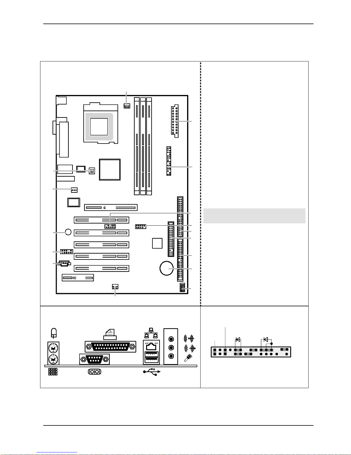
Interne Anschlüsse und Steckplätze / In ternal
connectors and slots
16
DIMM 1
DIMM 2
CPU
Pentium 4
DIMM 3
15
14
AGP
PCI 1
13
12
11
PCI 2
PCI 3
PCI 4
PCI 5
CNR
1 = Stromversorgung / Power supply
2 = Bedienfeld / Front panel
3 = USB C/D
4 = USB E/F
5 = Diskettenlaufwerk / Floppy disk drive
6 = IDE-Laufwerke 3/4 / IDE-drives 3/4
7 = IDE-Laufwerke 1/2 / IDE-drives 1/2
8 = Batterie / Battery
1
9 = Schalter / Switch
10 = Lüfter 2 / Fan 2
11 = CD-Audio in
12 = Audio-Bedienfeld / Audio front
panel
13 = Summer / Buzzer
2
14 = S/PDIF-Anschluss / S/PDIF
connector
15 = Prozessor-Stromversorgung /
Processor power supply
16 = Lüfter 1 / Fan 1
Optionale Komponenten / Optional
3
components
4
5
6
7
8
10
Externe Anschlüsse / External connectors
A26361-D1555-Z120-1-6319 Umschlag/Cover
LAN
AUDIO
9
Bedienfeld / Front panel
Power On/Off
1)
HD-LED
1)
Reset
1) Cable is not included in the delivery scope.
2) The same interfac e
3) 2pin or 3pin connector possible
Power On
1) 3)
LED
1
2
Page 8

Page 9

Contents
Mainboard D1555.............................................................................................................................1
Notational conventions ..............................................................................................................1
Important notes..................................................................................................................................2
Information about boards...........................................................................................................2
List of features...................................................................................................................................3
Special features.........................................................................................................................4
Brief instructions on installing mainboard...........................................................................................5
Prior to installation.....................................................................................................................5
Interfaces and connectors..............................................................................................................7
External ports....................................................................................................................................7
Internal ports and connectors ............................................................................................................7
Hard disk connection.................................................................................................................7
Pin assignment of internal ports.........................................................................................................8
Settings with switches and jumpers............................................................................................12
Add-on modules / Upgrading........................................................................................................13
Replacing processor ........................................................................................................................13
Removing and installing processors ........................................................................................13
Upgrading main memory..................................................................................................................15
Upgrading AGP screen controllers...................................................................................................16
Adding PCI cards.............................................................................................................................16
PCI bus interrupts - Selecting correct PCI slot.........................................................................16
Replacing the lithium battery....................................................................................................18
BIOS update....................................................................................................................................19
BIOS Recovery - Recovering System BIOS ...................................................................................20
Microcode Update ...........................................................................................................................20
Drivers .............................................................................................................................................21
Annex.............................................................................................................................................22
Electrical Properties.........................................................................................................................22
APM and ACPI system status, energy-saving modes...................................................................... 23
Mainboard Revision and BIOS Version............................................................................................24
Error messages .............................................................................................................................25
Glossary..........................................................................................................................................29
A26361-D1555-Z120-1-6319
Page 10

Page 11
Mainboard D1555
Your mainboard is availabl e i n di fferent configuration l evels. Depending on the confi guration chosen,
some of the hardware component s described may not be av ai l abl e on your mainboard.
Further information
Information on the BIOS Setup and addit i onal descriptions of the dri vers are contained:
• in the readme files on y our hard di sk
• on the driver floppy disks included
• on the CD "Drivers & Utilities Collection" or "Drivers & Utilities" or "ServerStart".
The programme Acrobat Reader must be installed to be abl e to open the manuals. You
i
Notational conventions
may find the programme on t he CD-ROM di rectory: utls/ acrobat.
For more details please read t he according readme.txt files.
The meanings of the sy m bol s and fonts used in this manual are as follows:
indicates inform ation which is important for your health or for prevent i ng physical
!
i
Ê Text which follows this symbol describes ac t i vities that must be performed in the order shown.
Ë This sym bol i ndi cates that you mus t enter a blank space (press the Space Bar) at this poi nt.
Ú This symbol indicates that you mus t press the Enter key.
Text in this typeface indicates sc reen outputs.
Text in this bold typeface indicates the ent ri es you make via the k eyboard.
Text in italics indicates commands or menu items.
"Quotation marks " i ndi cate names of chapters or terms.
damage.
indicates additi onal i nformation which is required t o use the system properly.
A26361-D1555-Z120-1-6319 English - 1
Page 12
Important notes
Important notes
With the mainboard installed you must open the system to access the mainboard. How to dismantle
and reassemble the system is described in the operating manual accompanying the system.
Connecting cables f or peri pheral s must be adequately s hi el ded t o avoid interference.
Observe the safety notes in the operating manual of your system.
!
Incorrect replacem ent of the lithium batt ery may lead to a risk of explosion. It is therefore
essential to obs erve the instructions in the "Add-on modules / Upgradi ng" - " Repl acing
the lithium battery" section.
Components can become v ery hot during operation. Ensure you do not touch
components when making extensions to the m ai nboard. There i s a danger of burns!
The shipped version of t hi s board complies with t he requi rem ents of the EEC direct ive
89/336/EEC "Electromagnetic compatibility".
Compliance was tested in a typical PC c onfiguration.
When installing the board, refer to the s pecific installation information in the manual for
the receiving device.
The warranty is invalidated if the system is damaged during the installation or
i
replacement of expans i ons. Information on whic h expansions you can use i s available
from your sales out l et or the customer service centre.
Information about boards
To prevent damage to the mainboard, the components and conductors on it, please take great care
when you insert or remove boards . Take great care to ensure that extension boards are sl ot ted in
straight, without damaging components or conductors on the mainboard, or any other components,
for example EMI spring contacts.
Remove the plug from the mains outlet so that system and mainboard are totally disconnected from
the mains voltage.
Be careful with the l ocking mechanisms (catches, c ent ri ng pi ns etc.) when you replace the
mainboard or components on it , for example memory m odul es or processors.
Never use sharp objects (screwdrivers) for l everage.
Boards with electrostatic sensi tive devices (E S D) are i dentifiable by the label s hown.
When you handle boards fitt ed wi t h ESDs, you must , under all circumst ances,
observe the following:
• You must alway s discharge stati c build up (e.g. by touchi ng a grounded obj ect)
before working.
• The equipment and tools you use must be free of s tatic charges.
• Remove the power plug from the mains supply before i nserting or removing
boards containing ESDs.
• Always hold boards with ESDs by thei r edges.
• Never touch pins or conductors on boards fit ted with ESDs.
2 - English A26361-D1555-Z120-1-6319
Page 13

List of features
Onboard features D1555-A
Chipset SiS 648 / 963
Board size ATX
VGA -
Audio ü
Buzzer / int. Speaker Support ü / -
LAN / with Alert-on-LAN ü / -
IDE RAID -
FireWireTM / 1394 / i.LINK
HI-SPEED USB 2.0 ü
SmartCard Reader Support (USB / serial) - / -
Temperature monitoring System Monitoring -
Fujitsu Siemens Com puters Keyboard Power Butt on S upport -
Internal ports
®
-
DIMM slots (DDR 333 SDRAM / DDR 266 SDRAM) 2 / 3
AGP Slot (4/8x, 32 bit, 66 MHz, 1.5 V) 1
PCI slot (32-bit, 33 MHz, 5 V and 3.3 V) 5
CNR Slot (Type A, AC‘97 only) 1
IDE RAID interface (RAID 1,2 / IDE 3,4) -
IDE Interface (Ul tra DMA/133) 2
Floppy Interface (up to 2.88 Mbyte) 1
S/PDIF* (digital audio) 1
CD / AUX audio input 1 / -
Frontpanel Audio (headphone, microphone) 1
Wake On LAN -
IEEE 1394 connector* (FireWireTM / i.LINK®)-
USB Ports* (2.0, ~480 MB/s) 4
Serial Ports* (FIFO, 16550 compatible) -
Fan Connectors PSU** / CPU / AUX1 / AUX2 - / 1 / 1 / -
SMBus Connector* (Case Temperature)Intrusion Connector* (Cas e Open) Power Connectors ATX / ATX12V / AGP PRO 1 / 1 / -
A26361-D1555-Z120-1-6319 English - 3
Page 14

List of features
External ports
VGA -
Audio Mic. in / Line in / Line out (32 Ω headphones capable) 1 / 1 / 1
Game/MIDI -
LAN (RJ-45) 1
PS/2 mouse/keyboard 1 / 1
USB Ports (2.0, ~480 M B/s) 2
Serial Ports (FIFO, 16550 compatible) 1
Parallel Port (EPP/ECP) 1
* for use with internal devices or optional Front or Rear panel
** not supported by standard power supplies
Special features
Your mainboard is availabl e i n di fferent configuration l evels. Depending on the confi guration, your
mainboards is equipped with or supports the features described in the following.
DeskView / DeskViewOEM
The network-capable manageability sof tware DeskView/DeskViewOEM* mainly
consists of three modules:
• DeskInfo shows the most important device data of the PCs i n a net work (local
and/or on an administrator P C).
• DeskAlert monitors t he operabilit y of all major components and triggers alarms if
necessary depending on the m ai nboard variant.
• DeskFlash carri es out a BIOS update under Windows.
Recovery BIOS
If an error occurs during a B IOS update (e.g. due to a power fail ure), the system BIOS
will be destroyed. All Fujitsu Siemens Computers mainboards are equipped with a
recovery BIOS. Wi th it a destroyed BIOS can easily be restored. Exact inst ructions
are provided in the chapter "BIOS Recovery - Rec overing System BIOS".
IA-PC
Instantly Available PC ensures fast availability of t he PC from an energy-saving mode.
Within just a few seconds the PC is in exactly the sam e state it was in when it was
switched off without time-consumi ng boot i ng. Depending on the operating system, the
PC can be switched into an energy-saving mode with appl i cations open by pressi ng
the ON/OFF switch.
4 - English A26361-D1555-Z120-1-6319
Page 15

Brief instructions on instal ling mainboard
If you have purchas ed a separate mainboard, you can install the mainboard in your system in
accordance with the following brief instructions.
The activities described here assume a bas i c knowledge of PCs and cannot be carried out by a
layperson. If y ou are not sure whether you have the nec essary specialised knowledge, then leave
this work to an expert.
The illustrations of the system show examples of possible cases.
Prior to installation
Ê Please take note of the safety information in the "I m portant notes" chapter.
Ê Check whether the processor, memory m odul es and power supply are suitabl e f or this
mainboard:
− (see "Replacing proces sor" chapter).
− (see "Upgrading main memory" chapter).
− (see "Electrical Properties" chapter).
Ê Make sure the current requirement of the f ans (processor, cas e) does not exceed the
loadability of the fan connections (see chapter entitled "Electrical Properties").
Ê First only install the components absolutely nec essary (graphics card, processor and heat sink,
one memory module) and only c onnect the required connections (power supply unit, c ase
connections such as ATX on/off switch, hard disk or floppy disk drive). You should not instal l
additional cards and devi ces until this m i ni m um configuration succ essfully boots (see chapter
entitled "Add-on modules / Upgrading".
A26361-D1555-Z120-1-6319 English - 5
Page 16

Brief instructions on installing mainboard
Installation
Ê Equip the mainboard with the processor, heat sink and memory modules before i nstallation if
possible. Further inf ormation can be found in "Replaci ng processor" chapter.
Ê Open the casing as described in the
operating manual.
Ê Should no suitable connection field be
provided in the case, t hen you must
install the connection field (1) provided.
Ensure the plate is al i gned properl y so that
the connections are suitable for the
mainboard later.
Ê Set the mainboard on the edge on
which the connecti on f ield is located (2)
and then insert the board in the
case (3).
Make sure that spacers in the housing are
only mounted at points at which there are
mounting holes in the mai nboard.
Ê Fasten the mainboard with the screws.
Ê Connect the plugs for the power supply, control panel and drives to t he corresponding
connections on the m ai nboard.
Driver installation
Ê Install the drivers for the chipset. You may find the driver on the "Drivers & Utilities" CD. Please
refer to chapter "Drivers" for a des cription of installing drivers.
6 - English A26361-D1555-Z120-1-6319
Page 17

Interfaces and connectors
The positions of the i nterfaces and connectors are shown on page "Cover".
The components and connectors marked are not necessarily present on the mainboard.
External ports
The positions of the external ports are shown on page "Cov er" .
PS/2 keyboard port, purple PS/2 mouse port, green
Serial interface, turquoise Parallel port/Printer, burgundy
LAN
LAN connector
This mainboard has an ADMt ek AN983B LAN controller. The LAN controller is equipped with a 2 KB
transmission and receiving buffer (FIFO) and s upport s WOL function through Magic Packetä.
The LAN RJ45 connector has t wo LEDs (light emitti ng di odes).
LAN connector USB - Universal Se ri al B u s, black
Audio output (Line out), l i ght green Microphone jack (mono), pi nk
Audio input (Line in), light blue
1 = a connection exists (e.g. to a hub).
2
1
2 = Link Mode: the LAN connect i on i s active.
WOL mode: a Magic Pack et
received.
TM
is being
Internal ports and connectors
The positions of the i nternal ports and connectors are shown on the Cover. Additi onal information on
some ports is also provided here.
Hard disk connection
An ultra ATA/66, ul t ra ATA/100 or ultra ATA/ 133 hard di sk must be connected with a cable
especially designed for the ultra ATA/66, ultra ATA/100 or ultra A T A /133 mode.
Ê Connect the end of the cable marked with blue to the mainboard.
A26361-D1555-Z120-1-6319 English - 7
Page 18

Pin assignment of internal ports
Pin assignment of internal ports
The pin assignment of some internal connections is shown in Englis h and/or German in the
following.
i
Bedienfeld / Front panel
Watch the poling of the LE Ds. The positive pole
of the connection c abl es is often indicated with a
Some of the following connectors may be opti onal !
Power On/Off
1)
Reset
HD-LED
1)
Power On
1) 3)
LED
1
2
coloured wire.
Connection Note
Reset
Power On/Off
HD LED
Power On LED Indicates the system state APM or ACPI together with the Sleep LED (see
chapter entitled "A PM and ACPI system status, energy-saving modes").
USB
1 2
C/D - dual channel
E/F - dual channel
(internal or external vi a special cable)
Pin Signal Pin Signal
1 VCC C 2 VCC D
3 Data negative C 4 Data negative D
5 Data positive C 6 Data positive D
7 GND 8 GND
9 Key 10 not connected
8 - English A26361-D1555-Z120-1-6319
Page 19

Pin assignment of internal ports
Audio-Bedienfeld / Audio front panel
Pin Signal Pin Signal
1 Micro input 2 Analog GND
3 Micro bias 4 Analog VCC
5 Right line output 6 Right line return
7 not connected 8 Key
9 Left line output 10 Lef t line return
If the audio front panel i s not used, you must pl ug j um pers on pinpairs 5/6 and 9/10.
Audio S/PDIF
Pin Signal
1VCC
2 SPDIF out
3GND
1 2
1
CD-ROM audio
Pin Signal
1 Left CD audio input
2 CD GND
3 CD GND
4 Right CD audio input
1
A26361-D1555-Z120-1-6319 English - 9
Page 20

Pin assignment of internal ports
Lüfter 1 / Fan 1
(processor fan - only for 3 pin fans)
Pin Signal
1GND
2 Fix Fan voltage (+12 V, m ax. 1 A)
3 Fan sense
Lüfter 2 / Fan 2
(system fan - only for 3 pin fans)
Pin Signal
1GND
2 Fix Fan voltage (+12 V, m ax. 1 A)
3 Fan sense
Stromversorgung ATX1 2 V /
1
1
13
Power supply ATX12 V
Pin Signal Pin Signal
1 GND 2 GND
3 +12 V 4 +12 V
10 - English A26361-D1555-Z120-1-6319
Page 21

Pin assignment of internal ports
Stromversorgung ATX /
Power supply ATX
Pin Signal Pin Signal
1 +3.3V(P2V2P) 11 +3.3V(P2V2P)
2 +3.3V(P2V2P) 12 -12V (P12VN)
3GND13GND
4 +5V (VCC) 14 PS on (low asserted)
5GND15GND
6 +5V (VCC) 16 GND
7GND17GND
8 Powergood (high asserted) 18 -5V (5PVN)
9 +5V Auxiliary (VCC Aux) 19 +5V (VCC)
10 +12V (P12VP) 20 +5V (V CC)
1
11
A26361-D1555-Z120-1-6319 English - 11
Page 22

Settings with switches and jumpers
The positions of the switches and jumpers are shown on page "Cover".
Skipping system and BIOS Setup password - switch 1
Switch 1 enables skipping the system and BIOS Setup password.
On System and BIOS Setup password are s kipped when the device is s wi tched on and
may be changed.
Off System and BIOS Setup password must be entered when the dev i ce is switched on.
Recovering System BIOS - switch 2
Switch 2 enables recovery of the old system BIOS after an attempt to update has failed. To rest ore
the old system BIOS you need a Flash BIOS Diskett e (pl ease call our customer service centre).
On The System BIOS executes f rom floppy drive A: and the inserted "Flash-BIOS -
Diskette" res tores the System B IOS on the mainboard.
Off Normal operation (default set t i ng).
Reserved - switch 3 and switch 4
Switch 3 and 4 are reserved. The position of the switch doesn't matter.
A26361-D1555-Z120-1-6319 English - 12
Page 23

Add-on modules / Upgrading
Exit energy-saving mode, switch of f the system and remove the power plug from the
!
Replacing processor
Technical data
• Pentium 4 with 400/533 MHz Front Side Bus in the mP GA478 design.
• Celeron with 400 MHz Front Side B us in the mPGA478 design
A current list of the processors s upported by this mainboard is available on the Internet at:
www.fujitsu-siemens.de/mainboards.
Removing and installing processors
mains outlet, bef ore carrying out any of the procedures described in this chapter!
Even when you have swit ched off the device, parts (e.g. memory modul es, AGP and PCI
extension boards) are still supplied with power.
Ê Remove the fan that there may be and the heat s i nk.
2
3
3
1
1
Ê Pull the lever in the direction of the arrow (1) and lift it as far as it will go (2).
Ê Remove the old processor from the socket (3).
Ê Insert the new processor in the soc ket so that the angled c orner of the processor matches the
coding on the socket (A) with regard to the position (4).
2
4
4
5
5
A
A
The angled corner of the processor can also be at a different l ocation than shown in the
i
Ê Push the lever back down until it clicks into place (5).
A26361-D1555-Z120-1-6319 English - 13
illustration.
Page 24

Replacing processor
Mounting heat sink
Be sure to use heat conducting material between the processor and the heat sink. If a heat
conducting pad (rubber-like foil) is already applied t o t he heat sink, then use i t . Otherwise you must
apply a very thin layer of heat conducting pas te.
Heat conducting pads can only be used once. If you remove the heat sink, you must clean it and
apply new heat conducti ng paste before you remount it.
Please note that, dependi ng on the heat sink used, di f ferent heat sink mounts are required on the
mainboard.
If a counter-plate is mounted on the underside of the m ai nboard for reinforcement, no
i
heat sinks of t he type "Intel Boxed" may be used. Otherwise t he ret ai ni ng clips of the heat
sink will be damaged.
When using an "Intel Box ed" heat sink, the mainboard m ust be converted. This
conversion set i s either included with t he m ai nboard or i s available separately .
If no counter-plate is mounted, you can use bot h " Intel Boxed" heat si nks and standard
heat sinks. If you use the "Intel Boxed" heat sink, the mainboard will bend due to the high
pressure of the retaining clips. This behavi our i s specified by I nt el .
Ê Depending on the configuration variant, you
must pull a protect ive foil off the heat sink or
coat the heat sink wi th heat conducting past e
before fitting it .
Ê Depending on the processor variant, cli ps
may also be supplied f or mounting the heat
sink that fix it in place.
Ê When you have mounted the optional fan,
connect the fan plug t o the corresponding
connection on the mainboard.
14 - English A26361-D1555-Z120-1-6319
Page 25

Upgrading main memory
Upgrading main memory
Technical data
Technology: DDR 266 or DDR 333 unbuffered DIMM modules
184-Pin; 2.5 V; 64 Bi t, no ECC
Size: 32 Mbytes to 3 Gby t e DDR 266 SDRAM
32 Mbytes to 2 Gby t e DDR 333 SDRAM
Granularity: 32, 64, 128, 256, 512 or 1024 Mbyte for one socket
A current list of the memory modules rec ommended for this mainboard is available on the Internet
at: www.fujitsu-siemens.de/mainboards.
At least one memory module must be inst al l ed. You may only use three double-sided memory
modules for DDR 266 modules. You may only use up to t wo double-sided, three single-si ded
memory modules or one double-s i ded with two single-sided memory modules for DDR 333.
Memory modules wit h di fferent memory capac i t ies can be combined.
You may only use unbuf f ered 2,5 V memory modules. Buffered memory modul es are not
!
supported.
DDR-DIMM memory modules must meet the P C2100 or P C2700 specification.
Installing a memory module
2
2
Ê Push the holders on each side of the memory compartment outwards .
Ê Insert the memory module into the l ocation (1).
Ê At the same time flip the lateral holders upwards until the memory module snaps in place (2).
A26361-D1555-Z120-1-6319 English - 15
Page 26

Upgrading AGP screen controllers
Removing a memory module
1
Ê Push the clips on the right and left of the compartment outward (1).
Ê Carefully remove the memory module f rom the compartment (2).
1
Upgrading AGP screen controllers
Technical data:
The AGP slot support s the modes 4x/8x with 32 bits and 66 MHz. Only 1.5 V AGP screen
controllers are support ed.
Some older 3.3 V AGP screen controllers are coded l i ke 1.5 V AGP screen controllers.
i
The installation of such 3.3 V AGP screen controllers can cause serious damage to the
mainboard and the AGP sc reen controller.
Adding PCI cards
Technical data:
32 bit / 33 MHz PCI s l ots
5 V and 3.3 V supply v ol tage
3.3 V auxiliary voltage
PCI bus interrupts - Selecting correct PCI slot
To achieve optimum stability, performance and compatibility, avoid the multiple use of
i
ISA IRQs or PCI IRQ Lines (IRQ sharing). Should IRQ sharing be unavoidable, then all
involved devices and their drivers must support IRQ sharing.
PCI IRQ Lines connect AGP slots, PCI slots and onboard components to the interrupt controller.
PCI IRQ Lines are permanently wired on the mainboard.
Which ISA IRQs are assigned to the PCI IRQ Lines is normally automatically specified by the BIOS
(see description in "BIOS Setup").
16 - English A26361-D1555-Z120-1-6319
Page 27

Adding PCI cards
Monofunctional expansions cards:
Standard AGP and PCI expansion cards require a maximum of one interrupt, which is called the PCI
interrupt INT A. Expansion cards that do not require an interrupt can be installed in any desired slot.
Multifunctional expansion cards or expansion cards with integrated PCI-PCI bridge:
These expansion cards require up to four PCI interrupts: INT A, INT B, INT C, INT D. How many and
which of these interrupts are used is specified in the documentation provided with the card.
The assignment of the PCI interrupts to the PCI IRQ Lines is shown in the following table:
Onboard Controller PCI slot
USB 1,1 AC97
PCI
Interrupt
Line
st
1
nd3rd
2
1 2 3 4 5
USB 2,0
SMBus
Audio
Modem
LAN
AGP
1 (A) ---- - - - - ACBADC
2 (B) ---- B- - - B DCBAD
3 (C) ---- - C- - - ADCBA
4 (D) ---- - - - D- BADCB
5 (E) E------------6 (F) -F-----------7 (G) --G----------8 (H) ---H- - - - - - - - - -
Use the first P CI slots that have a s i ngl e PCI IRQ Line (no IRQ sharing). If you must use another
PCI slot with I RQ sharing, check whether t he expansion card properly support s IRQ sharing with the
other devices on this PCI IRQ Line. The drivers of all cards and components on this PCI IRQ Line
must also support I RQ sharing.
A26361-D1555-Z120-1-6319 English - 17
Page 28

Adding PCI cards
Replacing the lithium battery
In order to permanently s ave the system information, a lithium battery is installed to provide the
CMOS-memory with a c urrent. A corresponding error mes sage notifies the user when the charge is
too low or the battery is empty. The lithi um bat tery must then be replac ed.
Incorrect replacem ent of the lithium batt ery may lead to a risk of explosion!
!
The lithium battery holder exists in dif ferent designs that function in the same way.
The lithium battery m ay be replaced only with an identical battery or with a t ype
recommended by the manufacturer.
Do not throw lithium batteries into the household waste. They must be disposed of in
accordance with loc al regul ations concerning special waste.
Make sure that you i nsert the battery the ri ght way round. The plus pole must be on the
top!
2
4
2
3
1
3
Ê Press the locking lug in the direction of the arrow; the battery jumps somewhat out of the
holder (1).
Ê Remove the battery (2).
Ê Push the new lithium bat tery of the identical type into the holder (3) and press i t downward until
it engages (4).
18 - English A26361-D1555-Z120-1-6319
Page 29

BIOS update
BIOS update
When should a BIOS update be carried out?
Fujitsu Siemens Computers makes new BIOS versions available to ensure compatibility to new
operating systems, new software or new hardware. In addition, new BIOS funct i ons can also be
integrated.
A BIOS update should al ways also be carried out when a problem exists that cannot be solved with
new drivers or new software.
Where can I obtain BIOS updates?
The BIOS updates are avail abl e on the Internet at www.fujitsu-siemens.de/mainboards.
How does a BIOS update work?
You have two ways of doi ng this:
1. BIOS update under DOS with bootable BIOS update fl oppy di sk - bri ef description
Ê Download the update file from out website to your PC.
Ê Insert an empty floppy disk (1.44 MB).
Ê Run the update file (e.g. 1522103.EXE).
Ê A bootable update floppy disk is created. Leave this fl oppy disk in the drive.
Ê Restart the PC.
Ê Follow the instructions on screen.
Detailed information on t he BIOS update under DOS is provi ded i n the manual on "BIOS
i
2. BIOS update under Windows with DeskFlash utility
A BIOS update can also be carried out directly under Windows with the Des kFlash utility. DeskF lash
is located on the "Drivers & Utilities" CD (from CD version 2001.05 wit h DeskView
Readme file in the subfolder DeskFlash you will find the installation instructions for DeskFlash. Further
information on DeskFlash is provided in t he file "DeskView.P DF" and i n t he DeskView
help.
Setup" ("Drivers & Utilities" CD).
OEM
V5.0). In the
OEM
online
A26361-D1555-Z120-1-6319 English - 19
Page 30

BIOS Recovery - Recovering S ystem BIOS
BIOS Recovery - Recovering System BIOS
i
Ê Open the casing as described in the operating m anual .
Ê Set the switch for "Restore system BIOS" to ON.
Ê Close the casing as described in t he operat i ng m anual.
Ê Insert a BIOS update floppy disk and start the PC.
Ê Note the signals issued from the l oudspeaker. You have successfully res t ored the BIOS if you
Ê Open the casing as described in the operating m anual .
Ê Set the switch for "Restore system BIOS" to OFF.
Ê Close the casing as described in t he operat i ng m anual.
Ê Remove the floppy disk from the dri ve.
Ê Start the PC and invoke BIOS Setup.
Ê Select the menu item Reset Configuration in the menu Advanced and change the s etting to Yes.
Ê Save the change and terminate BIOS Setup.
The BIOS recovery has now been completed. The system restarts.
All BIOS set tings are reset to the defaul t values.
hear the signal sequence “s hort-short- long- long- long" and the dis kette access i ndi cator is
dark. This can take a few minutes.
Detailed information on t he BIOS recovery is contained in the manual "BI OS Setup"
i
("Drivers & Utilities" CD).
Microcode Update
What is a microcode update?
Da es für Prozessoren k eine Treiber gibt , bietet Intel ab den Prozes soren der P6-Familie (Pentium
Pro) die Möglichkeit, den Befehlssatz (Microcode) des Proz essors zu aktualisieren. This enables
minor errors to be correct ed and the performance to be increas ed.
To guarantee the best possi bl e performance and error-free operation, Intel recommends updating
the microcode for ev ery new processor. Int el refers to the use of the processor without microcode
updates as operation outs i de the specificati ons.
20 - English A26361-D1555-Z120-1-6319
Page 31

Drivers
Safety for processor on Fujitsu Siemens Computers mainboards
If the processor uses an old or incorrect m i crocode, error-free operation cannot be ensured. Fujitsu
Siemens Computers has therefore implemented a function on its mainboards that interrupts the
booting process if no suitable microcode is available for the inst al l ed processor. The output error
message is
Patch for installed CPU not loaded. Please run the bios flash update
diskette.
This message appears unt i l the microcode update has been c arri ed out . If the computer is
nevertheless operated wi thout a microcode update, error-free operation is not ensured.
When should a microcode update be carried out?
A microcode update s houl d be carried out after the inst al l ation of a new processor.
In contrast to the BIOS update, only an updat ed version of the processor command set is stored.
The system BIOS remains unaffected by this.
Microcode update under DOS with bootable microcode update floppy disk - brief descri p ti on
Ê Download the update file from out website to your PC.
Ê Insert an empty floppy disk (1.44 MB).
Ê Run the update file under DOS (e.g. 1495101.EXE).
Ê A bootable update floppy disk is created. Leave the floppy di sk in the drive.
Ê Restart the PC.
Ê Follow the instructions on screen.
To determine whether the lates t microcode update has been loaded, the so-called Patch-ID of the
processor can be read out.
Ê Press the [F1] key in the BIOS Setup.
The entry CPU / Patch ID is shown on the displayed i nformation page.
A list with t he current processors and t he rel ated Patch-IDs is available on the Internet..
If the processor i s not recognised, you al so require the microcode update t ool for
i
processors of t he P 6 family.
Drivers
Only when no drivers are installed on your system, or you want to update these, proceed as f ol l ows:
Ê Insert the CD "Drivers & Utilities Collection" into the CD ROM drive.
Ê If the CD does not start automati cally, run the START.EXE programme in the main directory of
the CD.
Ê Select DeskUpdate - Fully automatic installation.
Ê Follow the instructions on screen.
A26361-D1555-Z120-1-6319 English - 21
Page 32

Annex
Electrical Properties
Loadability for connections and fuses
i
The fuses on this m ai nboard can be used several times (polyfuses). S hortly after the error st at e has
been eliminated, the fuses reset to the origi nal state.
Mainboard current requirement
You require a Pentium4 power supply nit as per the ATX12V specification f or this mainboard. If you
do not have a PC from Fujit su Siemens Computer, make sure that the power supply uni t provides
the required amperages.
Make sure that the c onnected devices do not overload the connections.
Fuse No. Fuse Connection Maximum loadability
- - Fan1, Fan2 1000 mA each
1 750 mA Keyboard Not specified
Mouse Not specified
VGA connector Mini m um 50 mA
2 2000 mA USB port A
USB port B
USB port C
USB port D
3 2000 mA USB port E
USB port F
500 mA
500 mA
Source Voltage Maximum difference Maximum current
ATX12V power supply +12 V ±5 % 12 A
ATX12V power supply -12 V ±10 % 0,05 A
ATX12V power supply +5,0 V ±5 % 19,5 A
ATX12V power supply +3.3 V ±5 % 3,7 A
Standby voltage of power supply unit +5.0 V SB ±5 % 2 A
The specificat i ons apply to the onboard components and represent the least f avourable case. In
addition, at least 350 m A is required for PCI on 3.3 V , and 500 mA per connected devic e for USB on
5 V.
A26361-D1555-Z120-1-6319 English - 22
Page 33

APM and ACPI system status, energy-saving modes
APM and ACPI system status, energy-saving modes
System status ACPI
Status*
Normal
operation
Simple energy-
saving mode
Maximum
energy-saving
mode **
"Save to DRAM"
Maximum
energy-saving
mode **
"Save To Disk"
“Soft Off" G2 S5 Soft Off Nearly zero Full boot time
Mechanically Off G3 Off
* G = Global status; S = S ystem status
** The power supply unit must provide suffici ent l y loadable 5 V standby vol tage.
G0 S0 On To Normal
G1
S1 Standby Almost like
S3
S4 Wake-up
APM
Status
Power
LED
flashing
Off
Power
consumptio
n
normal
RAM,
wake-up
components
components
Zero Full boot time
Wake-up time
Almost
immediately
ca. 20s
ca. 5s
To use the WOL functionality the power supply must provide a 5 V auxiliary voltage (5V SB) of at
least 1 A.
A26361-D1555-Z120-1-6319 English - 23
Page 34

Mainboard Revision and BIOS Version
Mainboard Revision and BIOS Ver sion
The compatibility, e.g. wit h new processors, can be independent of the BIOS version or the rev i sion
status of the mainboard used. The CPU and BIOS compat ibilit y lists are available on the Internet at
www.fujitsu-siemens.de/mainboards
Mainboard Revision
The revision stat us of the mainboard exactl y identifies which mainboard you have. It is indicated on
a sticker on the edge of the mainboard:
Example Mainboard-Revision
.
D1555-B10 GS 1
05618476
BIOS version
The BIOS version c an be displayed in the BIOS Setup.
Ê Press [F2] during booting to open the BIOS S et up.
Ê Press [F1].
The BIOS version is specified on the dis pl ayed information page under the entry BIOS Release.
24 - English A26361-D1555-Z120-1-6319
Page 35

Error messages
This chapter contai ns error messages generated by t he m ai nboard.
Available CPUs do not support the same bus frequency - System halted!
Memory type mixing detected
Non Fujitsu Siemens Memory Module detected - Warranty void
There are more than 32 32 RDRAM devices in the system
Check whether the system configuration has changed. If necessary, correct t he settings.
BIOS update for installed CPU failed
This message appears if the microcode update required f or the connected process or i s not
contained in the system BIOS.
Ê Boot the system with the inserted Flash BIOS floppy disk.
Ê Abort the normal Flash BIOS update by ans weri ng the question about whether you want to
perform the update with
n Ú
Ê To carry out the Flash BIOS update for t he processor, enter:
flashbioË/p6 Ú
Check date and time settings
The system date and time are invalid. Set the current date and time i n the Main menu of the
BIOS Setup.
CPU ID 0x failed
Switch the server off and on again. If the message is still displayed, go into the BIOS setup and
set the corresponding processor to Disabled in the Server - CPU Status menu; please contact
your sales outlet or customer servic e centre.
CPU mismatch detected
You have replaced the processor or changed the frequency setting. As a res ul t , the
characteristi c data of the processor have changed. Confirm this change by running the BIOS
Setup and exiting it again.
Diskette drive A error
Diskette drive B error
Check the entry f or t he di skette drive in t he Main m enu of the BIOS Setup. Check the
connections to t he di skette drive.
A26361-D1555-Z120-1-6319 English - 25
Page 36

Error messages
DMA test failed
EISA CMOS not writable
Extended RAM Failed at offset: nnnn
Extended RAM Failed at address line: nnnn
Failing Bits: nnnn
Fail-Safe Timer NMI failed
Multiple-bit ECC error occurred
Memory decreased in size
Memory size found by POST differed from EISA CMOS
Single-bit ECC error occurred
Software NMI failed
System memory exceeds the CPU’s caching limit
System RAM Failed at offset: nnnn
Shadow RAM Failed at offset: nnnn
Switch the device off and on again. If the message is still displayed, please contact your sales
outlet or custom er service centre.
Failure Fixed Disk 0
Failure Fixed Disk 1
Fixed Disk Controller Failure
Check the entry for the hard disk drive in the Main menu and the entry for the IDE dri ve
controller in the Advanced - Peripheral Configuration menu of the BIOS Setup. Check the hard
disk drive's connections and jumpers.
Incorrect Drive A - run SETUP
Incorrect Drive B - run SETUP
Correct the entry f or t he di skette drive in t he Main m enu of the BIOS Setup.
Invalid NVRAM media type
Switch the device off and on again. If the message is still displayed, please contact your sales
outlet or custom er service centre.
Invalid System Configuration Data
In the Advanced menu of the BIOS Setup set the entry Reset Configuration Data to Yes.
Invalid System Configuration Data - run configuration utility
Press F1 to resume, F2 to Setup
This error message may be di splayed if the machine was switched off during system start-up.
Call BIOS Setup and switch to the Advanced menu. S el ect the menu item Reset Configuration
Data and change the s etting to Yes. Sav e t he change and terminate BIOS Setup. Reboot the
device.
Keyboard controller error
Connect another keyboard or another mouse. If the message is still displayed, please contact
your sales outlet or customer servic e centre.
Keyboard error
Check that the keyboard is connected properly.
Keyboard error nn
nn Stuck Key
Release the key on the k eyboard (nn is the hexadecimal code for the key).
26 - English A26361-D1555-Z120-1-6319
Page 37

Error messages
Missing or invalid NVRAM token
Switch the device off and on again. If the message is still displayed, please contact your sales
outlet or custom er service centre.
Monitor type does not match CMOS - RUN SETUP
Correct the entry f or t he monitor type in the Main menu of the BIOS Setup.
On Board PCI VGA not configured for Bus Master
In the BIOS Setup, in the Advanced menu, submenu PCI Configuration, set the Shared PCI Master
Assignment entry to VGA.
One or more RDRAM devices are not used
One or more RDRAM devices have bad architecture/timing
One or more RDRAM devices are disabled
Contact your system administrator or contact our customer service centre.
Operating system not found
Check the entries for the hard disk drive and the floppy disk drive i n the Main menu and the
entries for Boot Sequence submenu of t he BIOS Setup.
Parity Check 1
Parity Check 2
Switch the device off and on again. If the message is still displayed, please contact your sales
outlet or custom er service centre.
Previous boot incomplete - Default configuration used
By pressing func tion key [F2] you can c heck and correct the settings in BIOS Setup. By
pressing function key [F1] the system starts with incomplete system configuration. If the
message is still display ed, please contact your sales outlet or customer service centre.
Real time clock error
Call the BIOS Setup and enter the correct time in the Main menu. If the message i s still
displayed, please contact your sales outlet or customer service centre.
Service Processor not properly installed
The server management cont rol l er has not been correctly installed. If the message is still
displayed, please contact your sales outlet or customer service centre.
Storage Extension Group = xy
Configuration error, x Storage Extensions(s) found, configured are y
SE(s).
Device List: k1, k2 ...
The specified number of storage expansion units (S Es) in the BIOS Setup menu Server - Storage
Extensions - Number of connected SE is incorrect. Check how many S Es within the group are
connected at the server and change the setting in BIOS Setup. Check whether you have
assigned the same dev i ce ID twice.
xy = Group number
x = Number of SEs found on the communication bus
y = Number of SEs entered in Number of connected SE
k1, k2 ... = Device ID of the storage extensions found
A26361-D1555-Z120-1-6319 English - 27
Page 38

Error messages
System battery is dead - Replace and run SETUP
Replace the lithium battery on the mainboard and redo the set tings in the BIOS Setup.
System Cache Error - Cache disabled
Switch the device off and on again. If the message is still displayed, please contact your sales
outlet or custom er service centre.
System CMOS checksum bad - - Default configuration used
Call the BIOS Setup and correct the previously m ade ent ri es or set the default entries.
System Management Configuration changed or Problem occurred
A system fan or system sensor has failed. Check the hardware operation.
System timer error
Switch the device off and on again. If the message is still displayed, please contact your sales
outlet or custom er service centre.
Uncorrectable ECC DRAM error
DRAM Parity error
Unknown PCI error
Switch the device off and on again. If the message is still displayed, please contact your sales
outlet or custom er service centre.
Verify CPU frequency selection in Setup
The frequency setti ng f or the processor is inv al i d. Correct the BIOS Setup and the set t i ng.
28 - English A26361-D1555-Z120-1-6319
Page 39

Glossary
Glossary
The technical terms and abbreviations given bel ow represent only a selecti on of the full list of
common technical terms and abbreviations .
Not all technical terms and abbreviations l i sted here are valid for the des cribed mainboard.
ACPI Advanced Configuration and
Power Management Interface
AC'97 Audio Codec '97 LAN Local Area Network
AGP Accelerated Graphic s Port LSA LAN Desk Service Agent
AMR Audio Modem Riser MCH Memory Controller Hub
AOL Alert On LAN MMX MultiMedia eXtens i on
APM Advanced Power Management P64H PCI64 Hub
ATA Advanced Technology
Attachment
BIOS Basic Input Output System P X E Preboot eXecution Environment
BMC Baseboard management
controller
CAN Controller Area Network RAMDAC Random Access M e m ory Digital
CPU Central Processi ng Uni t RDRAM Rambus Dynamic Random
CNR Com m uni cation Network Riser RIMM Rambus Inline Memory M odule
C-RIMM Continuity Rambus Inline
Memory Module
DIMM Dual Inline Mem ory Module SB Soundblaster
ECC Error Correcting Code SDRAM Synchronous Dynamic Random
EEPROM Electrical Erasable
Programmable Read Only
Memory
FDC Fl oppy disk controller SIMD St ream i ng M ode Instruction
FIFO First -I n Fi rs t-Out SMBus System Management B us
FSB Front S i de Bus SVGA Super Video Graphic A dapter
FWH Firm ware Hub USB Universal Serial Bus
GMCH Graphics and Memory Controller
Hub
GPA Graphics Performanc e
Accelerator
I2C Inter Integrated Circ ui t
IAPC Instantly A vailable Power
Managed Desktop PC Desi gn
ICH I/O Controller Hub
IDE Intelligent Drive Electronics
IPSEC Internet Protocol Security
ISA Industrial Standard Architecture
PCI Peripheral Component
Interconnect
RAM Random Access M em ory
Analogue Converter
Access Memory
RTC Real Tim e Cl ock
Access Memory
SGRAM Synchronous Graphic Random
Access Memory
(Single Instruction Multiple Data)
VGA Video Graphic Adapter
WOL Wake On LA N
A26361-D1555-Z120-1-6319 English - 29
 Loading...