

Page 1

answers
Mainboard D1544
Deutsch / English
2
Technisches Handbuch / Technical Manual
Page 2

Sie haben ...
... technische Fragen oder Probleme?
Wenden Sie sich bitt e an:
• Ihren zuständigen Vert ri ebspartner
• Ihre Verkaufs stelle
Weitere Informationen f i nden Sie im Handbuch "Sicherhei t" und "Ergonomie".
Aktuelle Inform ationen und Updates zu unseren Mainboards finden Sie im Internet:
http://www.fujitsu-siemens.com
Are there ...
... any technical problems or other questions you need clarified?
Please contact :
• your sales partner
• your sales out l et
You will find further information in the manuals "Safety" and "Ergonomics" .
The latest informat i on and updates on our mainboards can be found on t he I nternet under:
http://www.fujitsu-siemens.com
Page 3

Page 4

Dieses Handbuch wurde auf Recycling-Papier gedruckt.
This manual has been printed on recycled paper.
Ce manuel est imprimé sur du papier recyclé.
Este manual ha sido impreso sobre papel reciclado.
Questo manuale è stato stampato su carta da riciclaggio.
Denna handbok är tryckt på recyclingpapper.
Dit handboek werd op recycling-papier gedrukt.
Herausgegeben von/Published by
Fujitsu Siemens Computers GmbH
Bestell-Nr./Order No.:
Printed in the Federal Republic of Germany
AG 0403 04/03
A26361-D1544-Z120-1-7419
A26361-D1544-Z120-1-7419
Page 5

Mainboard D1544
Technisches Handbuch
Deutsch
English
Technical Manual
Ausgabe April 2003
April 2003 edition
Page 6

Intel, Pentium und Cel eron sind eingetragene Warenzeichen der Intel Corporation, USA.
Microsoft, MS, MS-DOS und Windows sind eingetragene Warenzeichen der Microsoft
Corporation.
PS/2 und OS/2 Warp sind ei ngetragene Warenzeichen von Internat i onal Business Machines,
Inc.
Alle weiteren genannten Warenzeichen sind Warenzeichen oder eingetragene Warenzeichen
der jeweiligen Inhaber und werden als geschützt anerkannt.
Copyright Fujitsu Siemens Computers GmbH 2003
Alle Rechte vorbehalten, insbesondere (auch auszugsweise) die der Übersetz ung, des
Nachdrucks, der Wiedergabe durch Kopieren oder ähnliche Verfahren.
Zuwiderhandlungen verpflicht en zu Schadenersatz.
Alle Rechte vorbehalt en, insbesondere für den Fall der Pat enterteilung oder GM-Eintragung.
Liefermöglichkeiten und technische Änderungen vorbehalten.
Dieses Handbuch wurde erst el l t von
cognitas. Gesel l schaft für Technik -Dok umentation mbH
www.cognitas.de
Intel, Pentium and Cel eron are regi stered trademarks of I ntel Corporation, USA.
Microsoft, MS, MS-DOS and Windows are registered trademarks of Microsoft Corporation.
PS/2 and OS/2 Warp are registered trademarks of Int ernat i onal Business Machines, Inc.
All other trademarks referenced are trademarks or registered trademarks of t heir respective
owners, whose protect ed ri ght s are acknowledged.
All rights, including rights of translation, reproduction by pri nting, copying or sim i l ar m ethods,
even of parts are reserv ed.
Offenders will be liable for damages.
All rights, including rights created by patent grant or regis t ration of a utility model or design,
are reserved. Delivery subject to availability.
Right of technic al m odi fication reserved.
This manual was produced by
cognitas. Gesel l schaft für Technik -Dok umentation mbH
www.cognitas.de
Page 7

Page 8
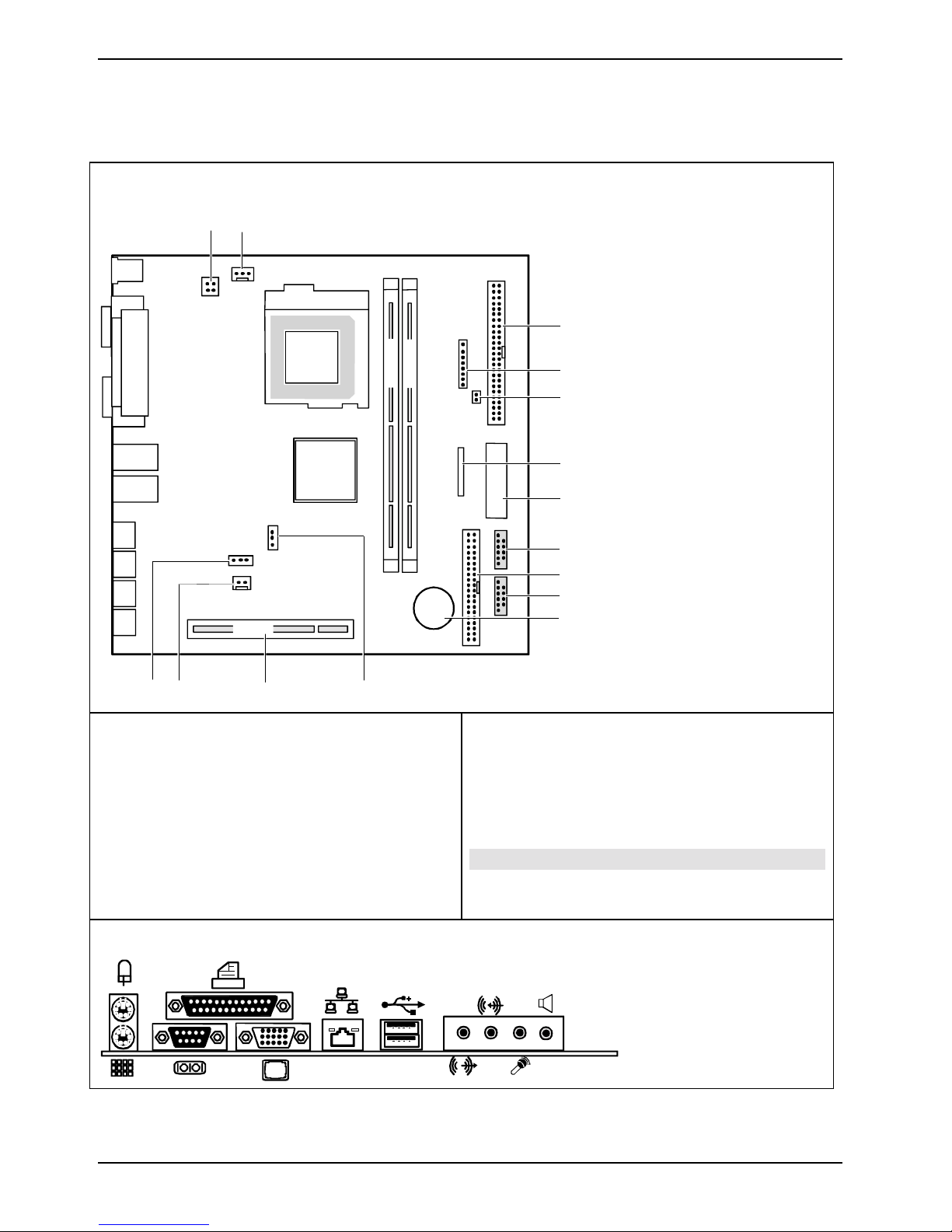
Übersicht/Overview Mainboard D1544
Interne Anschlüsse und Steckplätze / Internal connectors and slots
21
DIMM 1
CPU
Pentium 4
PCI
1415
1 = Stromversorgung Prozessor / Power supply
processor
2 = Lüfter Prozessor / Fan processor
3 = IDE-Laufwerke 3/4 / IDE drives 3/4
4 = Bedienfeld / Front panel
5 = Gehäuseöffnung / Intrusion
6 = Diskettenlaufwerk / Floppy disk drive
7 = Stromversorgung / Power supply
8 = USB C/D (SmartCard)
9 = IDE-Laufwerke 1/2 / IDE drives 1/2
1213
DIMM 2
3
4
5
6
7
8
9
10
11
10 = USB E/F
11 = Batterie / Battery
12 = Steckbrücke J4 / Jumper J4
13 = PCI-Steckplatz / PCI-Slot
14 = Lautsprecher-Anschluss / Speaker connector
15 = Steckbrücke 2 / Jumper 2
Optionale Komponenten / Optional components
Externe Anschlüsse / External connectors
A26361-D1544-Z120-1-7419 Umschlag/Cover
LAN
AUDIO
Page 9

Contents
Übersicht/Overview Mainboard D1544
Mainboard D1544.............................................................................................................................1
Notational conventions ..............................................................................................................1
Important notes..................................................................................................................................2
Information about boards...........................................................................................................2
List of features...................................................................................................................................3
Special features.........................................................................................................................4
Interfaces and connectors..............................................................................................................6
External ports ....................................................................................................................................6
LAN connector...........................................................................................................................6
Graphics port - Supported screen resolutions............................................................................7
Internal ports and connectors ............................................................................................................7
Hard disk connection.................................................................................................................7
Add-on modules / Upgrading..........................................................................................................8
Replacing processor..........................................................................................................................8
Removing and installing processors ..........................................................................................8
Mounting heat sink.............................................................................................................9
Upgrading main memory..................................................................................................................10
Adding PCI cards.............................................................................................................................11
PCI bus interrupts - Selecting correct PCI slot.........................................................................11
Replacing the lithium battery....................................................................................................13
Glossary....................................................................................................................... ...................14
A26361-D1544-Z120-1-7419
Page 10

Page 11

Mainboard D1544
Your mainboard is availabl e i n di fferent configuration l evels. Depending on the confi guration chosen,
some of the hardware component s described may not be av ai l abl e on your mainboard.
Further information
Additional descri pt i ons (e. g. of the drivers ) are contained:
• in the readme files on y our hard di sk
• on the driver floppy disks included
• on the CD "Drivers & Utilities Collection" or "Drivers & Utilities" or "ServerStart".
The programme Acrobat Reader must be installed to be abl e to open the manuals.
i
Notational conventions
For more details please read t he according readme.txt files.
The meanings of the sy m bol s and fonts used in this manual are as follows:
indicates inform ation which is important for your health or for prevent i ng physical
!
i
Ê Text which follows this s ymbol describes act ivities that m ust be performed in the order shown.
Ë This sym bol i ndi cates that you mus t enter a blank space (press the Space Bar) at this poi nt .
Ú This symbol indi cates that you mus t press the Enter key.
Text in this typeface indicates sc reen outputs.
Text in this bold typeface indicates the ent ri es you make via the k eyboard.
Text in italics indicates commands or menu items.
"Quotation marks " i ndi cate names of chapters or terms.
damage.
indicates additi onal i nformation which is required to use the system properly.
1 - English A26361-D1544-Z120-1-74191
Page 12

Important notes
Important notes
With the mainboard inst al l ed you must open the system to access the mainboard. How to dismantle
and reassemble the system is described in the operating manual accompanying the system.
Connecting cables f or peri pheral s must be adequately s hi el ded to avoid interference.
Observe the safety notes in the operating manual of your system.
!
Incorrect replacem ent of the lithium battery may lead to a risk of explosion. It is therefore
essential to obs erve the instructions in the "Add-on modules / Upgradi ng" - " Repl acing
the lithium battery" section.
Components can become very hot during operation. Ens ure you do not touch
components when making extensions to the m ai nboard. There i s a danger of burns!
The shipped version of t hi s board complies with t he requi rem ents of the EEC directive
89/336/EEC "Electromagnetic compatibility".
Compliance was tes t ed i n a typical PC confi guration.
When installing the board, refer to the specific installation informat ion in the manual for
the receiving device.
The warranty is invalidated if the system is damaged during the installation or
i
replacement of expans i ons. Information on whic h expansions you can use i s available
from your sales out l et or the customer service centre.
Information about boards
To prevent damage to the mainboard, the components and conductors on it, please take great care
when you insert or remove boards. Take great care to ensure t hat extension boards are sl otted in
straight, without damaging components or conductors on the mainboard, or any ot her components,
for example EMI spring contacts.
Remove the plug from the mains outlet so that system and mainboard are totally disconnected f rom
the mains voltage.
Be careful with the l ocking mechanisms (catches, c entring pins etc.) when you repl ace the
mainboard or components on it, for example memory m odul es or processors.
Never use sharp object s (screwdrivers) for l everage.
Boards with elect rostatic sensitive devices (E S D) are i dentifiable by the label s hown.
When you handle boards fitt ed wi t h E SDs, you must, under al l circumstances ,
observe the following:
• You must always discharge stat i c build up (e.g. by touchi ng a grounded obj ect)
before working.
• The equipment and tools you use must be free of static charges.
• Remove the power plug from the mains supply before i nserting or removing
boards containing ESDs.
• Always hold boards with ESDs by their edges.
• Never touch pins or conductors on boards fitted with ESDs.
A26361-D1544-Z120-1-7419 English - 2
Page 13

List of features
List of features
Onboard features D1544
Chipset i845G/GV
Board size 218,6 mm x 230 mm
VGA
Audio !
Buzzer / int. Speaker Support - / !
LAN / with Alert-on-LAN ! / !
IDE RAID FireWireTM / 1394 / i.LINK
HI-SPEED USB 2.0 !
SmartCard Reader Support (USB / serial) / -
®
-
Temperature monitoring !
System Monitoring !
Fujitsu Siemens Com puters Keyboard Power Butt on S upport !
Internal ports
DIMM slots (DDR 266 SDRAM) 2
AGP Slot (4/8x , 32 bi t, 66 MHz, 1.5 V) PCI slot (32-bit, 33 MHz, 5 V and 3.3 V) 2
CNR Slot (Type A, AC‘97 only) IDE Interface (Ul tra DMA/100) 1
Floppy Interface (up t o 1. 44 M byte) 1
S/PDIF* (digital audi o) CD / AUX audio input 1 / Frontpanel Audio (headphone, microphone) Wake On LAN
IEEE 1394 connector* (FireWireTM / i.LINK®)USB Ports* (2.0, ~480 MB/s) 2
Serial Ports* (FIF O, 16550 compatible) Fan Connectors PSU** / CP U / AUX1 / AUX2 - / 1 / - / SMBus Connector* (Cas e Tem perature) Intrusion Connector* (Cas e Open) !
3 - English A26361-D1544-Z120-1-7419
Page 14

List of features
External ports D1544
VGA 1
Audio Mic. in / Li ne in / Line out / Speaker out 1 / 1 / 1 / 1
Game/MIDI LAN (RJ-45) 1
PS/2 mouse/k eyboard 1 / 1
USB Ports (2.0, ~480 M B/s) 4
Serial Ports (FIFO, 16550 compatible) 1
Parallel Port (EPP/ECP) 1
* for use with internal devices or optional Front or Rear panel
** not supported by standard power supplies
Special features
Your mainboard is availabl e i n di fferent configuration l evels. Depending on the confi guration, your
mainboards is equipped wit h or supports the features described in the following.
Thermal Management and System Monitoring
A microcontroll er rel i abl y protects your PC agai nst damage caused by overheat i ng.
Overheating can lead to the data loss or processor dam age. An ingenious fan control
and monitoring system prevents unnecessary noise. Should the proc essor
nevertheless becom e too hot at the maximum fan speed, then the processor clock
rate will automatically be reduced so t hat the system continues to run stably. In
addition, the mic rocontroller offers monitoring of, for example, system voltages (12 V,
5 V, CMOS), opening of t he case and a watchdog funct i on.
The microcontroller operat es independently of the operati ng system and the
processor. All values are displayed wit h DeskView, DeskViewOEM or SystemGuard.
Harddisk Password
A password assignm ent for the hard disk is only possible with suitable, newer hard
disks and prevents unauthorised acc ess to the stored data.
Harddisk Password i s activated in the BIOS Setup.
A26361-D1544-Z120-1-7419 English - 4
Page 15

DeskView / DeskViewOEM
The network-capable manageability sof tware DeskView/DeskViewOEM mainly consists
of three modules:
• DeskInfo shows the most important device data of the PCs i n a network (local
and/or on an administrator P C).
• DeskAlert monitors t he operability of all major components and triggers alarms if
necessary depending on the m ainboard variant.
• DeskFlash c arri es out a BIOS update under Windows.
IA-PC
Instantly Available PC ensures fast availability of t he PC from an energy-saving mode.
Within just a few seconds the PC is i n exactly the sam e state it was in when it was
switched off without time-consumi ng booting. Depending on the operating system, the
PC can be switched into an energy-saving mode with appl i cations open by pressi ng
the ON/OFF switch.
List of features
5 - English A26361-D1544-Z120-1-7419
Page 16

External ports
Interfaces and connectors
The positions of the i nterfaces and connect ors are shown on page "Cover".
The components and connectors marked are not necessarily present on the mainboard.
External ports
The positions of the external ports are shown on page "Cov er" .
PS/2 keyboard port, purple PS/2 mouse port, green
Serial interface, turquoise Parallel port/Printer, burgundy
LAN
LAN connector USB - Universal S eri al Bus, black
Audio output (Line out), l i ght green Microphone jack (mono), pink
Audio input (Line in), li ght bl ue Speaker out, orange
VGA connector, bl ue (m oni tor)
LAN connector
This mainboard has an Intel GD82562EX LAN controller (10Bas e-T/ 100Base-TX). The LAN
controller is equipped with a 2 KB transmission and receiving buffer (FI FO) and supports WOL
function through Magic Packet.
The LAN RJ45 connector has two LEDs (light emitt i ng di odes).
1 = a connection exists (e.g. to a hub).
2
1
2 = Link Mode: the LAN connect i on i s active.
WOL mode: a Magic Packet
received.
TM
is being
A26361-D1544-Z120-1-7419 English - 6
Page 17

Internal ports and connectors
Graphics port - Supported screen resolutions
Depending on the operating system used, the screen resolutions in the following table refer to the
mainboard screen controller.
If you are using an external s creen controller, you will find details of supported screen resolutions in
the operating manual or techni cal manual supplied with t he controller.
Screen resolution Refresh rate (Hz) bpp Colour
640 x 480 120 32 32 bit
800 x 600 120 32 32 bit
1024 x 768 100 32 32 bit
1280 x 1024 100 32 32 bit
Internal ports and connectors
The positions of t he i nt ernal ports and connectors are s hown on the Cover. Additional inf ormation on
some ports is also provided here.
Hard disk connection
An ultra ATA/66 or ultra ATA/100 hard disk m ust be connected with a c abl e especially designed f or
the ultra ATA/66 or ultra ATA/100 mode.
Ê Connect the end of the cable marked with blue to the mainboard.
7 - English A26361-D1544-Z120-1-7419
Page 18

Add-on modules / Upgrading
Exit energy-saving mode, switch of f the system and remove the power plug from the
!
Replacing processor
Technical data
• Pentium 4 with 400/533 MHz Front Side Bus in the mPGA478 design up to 2.4 GHz
• Celeron with 400 MHz Front Side Bus in the mPGA478 desi gn up t o 2.0 GHz
Removing and installing processors
Ê Remove the fan that there may be and the heat s ink.
mains outlet, before carrying out any of t he procedures described in this chapter!
Even when you have swit ched off the device, parts (e.g. memory modul es, AGP and PCI
extension boards) are still supplied with power.
2
3
3
1
1
Ê Pull the lever in the direction of the arrow (1) and lift it as far as it will go (2).
Ê Remove the old processor from the socket (3).
Ê Insert the new processor in the soc ket so that the angled corner of the processor mat ches the
coding on the sock et (A) with regard to the positi on (4).
The angled corner of the processor can also be at a different location than shown in t he
i
Ê Push the lever back down until it clicks into place (5).
illustration.
2
4
4
5
5
A
A
8 - English A26361-D1544-Z120-1-74198
Page 19

Add-on modules / Upgrading
Mounting heat sink
Be sure to use heat conducting material between t he processor and the heat sink . If a heat
conducting pad (rubber-like foil) is already applied t o the heat sink, then us e i t . Otherwise you must
apply a very thin layer of heat conducting paste.
Heat conducting pads can only be used once. If you remove the heat sink, you must clean it and
apply new heat conducti ng paste before you remount it.
Please note that, dependi ng on t he heat sink used, different heat sink mounts are required on the
mainboard.
If a counter-plate is mounted on the underside of the mainboard for reinforcement, no
i
heat sinks of t he type "Intel Boxed" may be used. Otherwise the retaining clips of the heat
sink will be damaged.
When using an "Intel Box ed" heat sink, the mai nboard m ust be converted. This
conversion set i s either included with t he m ai nboard or i s available separately .
If no counter-plate is mounted, you can use bot h "Intel Boxed" heat s i nks and standard
heat sinks. If you use the "Intel Boxed" heat sink, the mainboard will bend due to the high
pressure of the retaining clips. This behavi our i s specified by I nt el .
Ê Depending on the configuration variant, you
must pull a protective foil off the heat sink or
coat the heat sink with heat conducting paste
before fitting it .
Ê Depending on the processor variant, cli ps
may also be supplied for mounting the heat
sink that fix it in place.
Ê When you have mounted the optional fan,
connect the fan plug t o the corresponding
connection on the mainboard.
9 - English A26361-D1544-Z120-1-7419
Page 20

Add-on modules / Upgrading
Upgrading main memory
Technical data
Technology: DDR 266 unbuffered DIMM modules
184-Pin; 2.5 V; 64 Bi t, no ECC
Size: 128 Mbytes to 1 Gby t e DDR 266 SDRAM
Granularity: 128, 256 or 512 Mbyte for one socket
At least one memory module must be inst al l ed. You may only use up to t wo double-sided or two
single-sided memory modules for DDR 266.
Memory modules wit h di fferent memory capac i ties can be combined.
You may only use unbuf fered 2,5 V memory modules . Buffered memory modules are
!
Installing a memory module
not supported.
DDR-DIMM memory modul es must meet the PC2100 specification.
2
2
Ê Push the holders on each side of the memory compartment outwards .
Ê Insert the memory module into the l ocation (1).
Ê At the same time flip the lateral holders upwards until the memory module snaps in place (2).
A26361-D1544-Z120-1-7419 English - 10
Page 21

Add-on modules / Upgrading
Removing a memory module
1
Ê Push the clips on the right and left of the compartment outward (1).
Ê Carefully remove the memory module f rom the compartment (2).
1
Adding PCI cards
Technical data:
32 bit / 33 MHz PCI s lots
5 V and 3.3 V supply v ol tage
3.3 V auxiliary voltage
PCI bus interrupts - Selecting correct PCI slot
To achieve optimum stability , perf ormance and compatibility, avoid the multiple use of ISA
i
PCI IRQ Lines connec t AGP slots, P CI slots and onboard components t o the interrupt controller.
PCI IRQ Lines are permanentl y wired on the mainboard.
Which ISA IRQs are assigned to the PCI IRQ Lines is normally automatically speci f i ed by the BIOS.
IRQs or PCI IRQ Lines (I RQ sharing). Should IRQ sharing be unav oi dabl e, then all
involved devices and their drivers must support IRQ sharing.
11 - English A26361-D1544-Z120-1-7419
Page 22

Add-on modules / Upgrading
Monofunctional expansions cards:
Standard AGP and PCI ex pansion cards require a maxim um of one i n t errupt, which is call ed the PCI
interrupt INT A. Expansion cards that do not requi re an i nt errupt can be installed in any desired slot.
Multifunctional expansion cards or expansion cards with integrated PCI-PCI bridge:
These expansion cards requi re up t o four PCI interrupts: INT A , INT B, INT C, INT D. How many
and which of these int errupt s are used is specif i ed i n the documentation provided wi t h the card.
The assignment of t he P CI interrupts to the PCI IRQ Lines is shown in the f ol l owi ng table:
Onboard Controller PCI slot
USB 1,1 AC97
PCI
Interrupt
Line
st
nd
1
2
rd
3
1 2
USB 2,0
SMBus
Audio
Modem
LAN
AGP
1 (A) A---------2 (B) ---- AA - - - - 3 (C) --A-------4 (D) -A-------CB
5 (E) ---- - - - A- - 6 (F) ---- - - - - - AD
7 (G) ---- - - - - - BA
8 (H) ---A- - - - - DC
Use the first P CI slots that have a s i ngl e PCI IRQ Line (no IRQ sharing). If you must use another
PCI slot with I RQ sharing, check whether t he expansion card properly support s IRQ sharing with the
other devices on thi s PCI IRQ Line. The drivers of all cards and components on this PCI IRQ Line
must also support IRQ sharing.
A26361-D1544-Z120-1-7419 English - 12
Page 23

Add-on modules / Upgrading
Replacing the lithium battery
In order to permanently s ave the system information, a lithium battery is installed to provide the
CMOS-memory with a c urrent. A corresponding error mes sage notifies the user when the charge is
too low or the battery is empty. The lithi um battery must then be replaced.
Incorrect replacem ent of the lithium battery may lead to a risk of explosion!
!
The lithium battery hol der exists in diff erent designs that func t i on i n the same way.
The lithium battery m ay be replaced only with an ident i cal battery or with a type
recommended by the manufacturer.
Do not throw lithium batteries into the household waste. They must be disposed of in
accordance with local regulations concerni ng special waste.
Make sure that you i nsert the battery the ri ght way round. The plus pole must be on the
top!
2
4
2
3
1
3
Ê Press the locking lug in the direction of the arrow; the battery jumps somewhat out of the
holder (1).
Ê Remove the battery (2).
Ê Push the new lithium battery of t he identical type int o the holder (3) and press it downward until
it engages (4).
13 - English A26361-D1544-Z120-1-7419
Page 24

Add-on modules / Upgrading
Glossary
The technical terms and abbreviations given bel ow represent only a selecti on of the full list of
common technic al t erms and abbreviations.
Not all technical terms and abbreviations l i sted here are valid for the des cribed mainboard.
ACPI Advanced Configuration and
Power Management Interface
AC'97 Audi o Codec '97 LAN Local Area Network
AGP Accelerated Graphic s Port LSA LA N Des k Service Agent
AMR Audio Modem Riser MCH Memory Controller Hub
AOL Alert On LAN MMX MultiMedia eXtens i on
APM A dvanced Power Management P64H PCI64 Hub
ATA Advanced Technology
Attachment
BIOS Basic Input Output System PXE Preboot eXecution Environment
BMC Baseboard management
controller
CAN Controller Area Network RAMDAC Random Access Memory Digital
CPU Central Processing Unit RDRAM Rambus Dynamic Random
CNR Com m uni cation Network Riser RIMM Rambus Inline Memory Module
C-RIMM Continuity Rambus Inline
Memory Module
DIMM Dual Inline Memory Modul e SB Soundblaster
ECC Error Correcting Code SDRAM Synchronous Dynamic Random
EEPROM Electrical Erasable
Programmable Read Only
Memory
FDC Fl oppy disk controller SIMD Streaming Mode Instruc tion
FIFO First -I n Fi rst-Out SMBus System Management B us
FSB Front Side Bus SVGA Super Video Graphic Adapter
FWH Firm ware Hub USB Universal Seri al B us
GMCH Graphics and Memory Cont rol l er
Hub
GPA Graphics Performanc e
Accelerator
I2C Inter Integrated Circ ui t
IAPC Instantly A vailable Power
Managed Desktop PC Desi gn
ICH I/O Controller Hub
IDE Intelligent Drive Electronics
IPSEC Internet Protocol Security
ISA Industrial Standard Architecture
PCI Peripheral Component
Interconnect
RAM Random Access M emory
Analogue Converter
Access Memory
RTC Real Tim e Cl ock
Access Memory
SGRAM Synchronous Graphic Random
Access Memory
(Single Instruction Multiple Data)
VGA Video Graphic Adapter
WOL Wake On LAN
A26361-D1544-Z120-1-7419 English - 14
 Loading...