

Page 1
COMPONENTS
Mainboard D1527 / D1526
Technisches Handbuch / Technical manual
Page 2

Sie haben ...
... technische Fragen oder Probleme?
Wenden Sie sich bitt e an:
· Ihren zuständigen Vert ri ebspartner
· Ihre Verkaufs stelle
Weitere Informationen f i nden Sie im Handbuch "Sicherhei t" und "Ergonomie".
Aktuelle Inform ationen und Updates (z. B. B IOS-Update) zu unseren Mainboards finden Sie im
Internet: http://www.fujitsu-siemens.com/mainboards
Are there ...
... any technical problem or other question you need clarified?
Please contact :
· your sales partner
· your sales out l et
You will find further information in the manuals "Safety" and "Warranty".
The latest informat i on and updates (e. g. BIOS update) on our m ai nboards can be found on the
Internet under: http://www.fujitsu-siemens.com/mainboards
Page 3

Page 4

Dieses Handbuch wurde auf Recycling-Papier gedruckt.
This manual has been printed on recycled paper.
Ce manuel est imprimé sur du papier recyclé.
Este manual ha sido impreso sobre papel reciclado.
Questo manuale è stato stampato su carta da riciclaggio.
Denna handbok är tryckt på recyclingpapper.
Dit handboek werd op recycling-papier gedrukt.
Herausgegeben von/Published by
Fujitsu Siemens Computers GmbH
Bestell-Nr./Order No.:
Printed in the Federal Republic of Germany
AG 0902 09/02
A26361-D1527-Z120-1-6319
A26361-D1527-Z120-1-6319
Page 5

Mainboard D1527 /
D1526
German
English
Technisches Handbuch
Technical manual
Ausgabe September 2002
September 2002 edition
Page 6

Intel, Pentium and Cel eron are regi stered trademarks of I ntel Corporation, USA.
Microsoft, MS, MS-DOS and Windows are registered trademarks of Microsoft Corporation.
PS/2 and OS/2 Warp are registered trademarks of Int ernat i onal Business Machines, Inc.
All other trademarks referenced are trademarks or registered trademarks of t heir respective
owners, whose protect ed ri ght s are acknowledged.
Copyright ã Fujitsu Siemens Computers GmbH 2002
All rights, including rights of translation, reproduction by pri nting, copying or sim i l ar m ethods,
in part or in whole, are reserved.
Offenders will be liable for damages.
All rights, including rights created by patent grant or regis t ration of a utility model or design,
are reserved.
Delivery subject to availability. Right of technical modification reserved.
This manual was produced by
cognitas. Gesel l schaft für Technik -Dok umentation mbH
www.cognitas.de
Intel, Pentium and Cel eron are regi stered trademarks of I ntel Corporation, USA.
Microsoft, MS, MS-DOS and Windows are registered trademarks of Microsoft Corporation.
PS/2 and OS/2 Warp are registered trademarks of Int ernat i onal Business Machines, Inc.
All other trademarks referenced are trademarks or registered trademarks of t heir respective
owners, whose protect ed ri ght s are acknowledged.
All rights, including rights of translation, reproduction by pri nting, copying or sim i l ar m ethods,
even of parts are reserv ed.
Offenders will be liable for damages.
All rights, including rights created by patent grant or regis t ration of a utility model or design,
are reserved. Delivery subject to availability.
Right of technic al m odi fication reserved.
This manual was produced by
cognitas. Gesel l schaft für Technik -Dok umentation mbH
www.cognitas.de
Page 7
Übersicht /Overview Mainboard
D1526/D1527
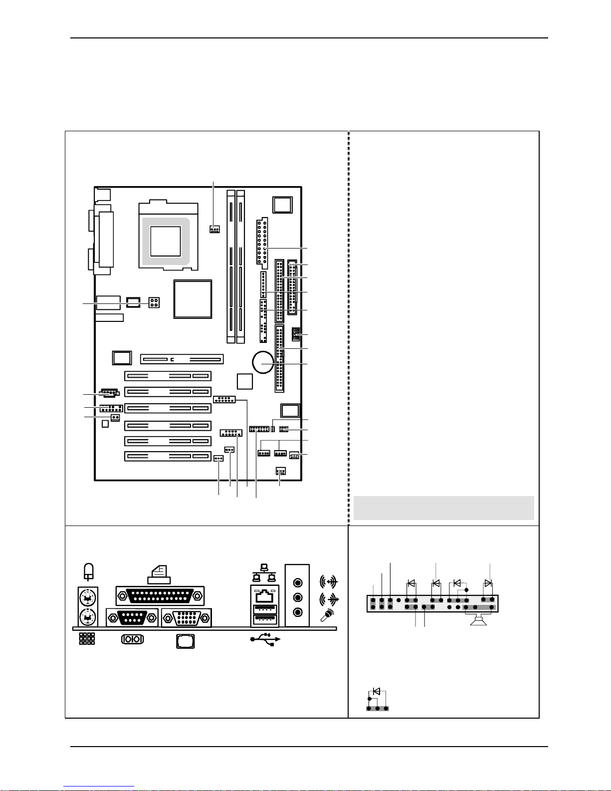
Interne Anschlüsse und Steckplätze / in ternal
connectors and slots
23
DIMM 1
DIMM 2
22
AGP
PCI 1
21
20
19
PCI 2
PCI 3
PCI 4
PCI 5
PCI 6
18
17
16
15
13
14
1
2
3
4
5
6
7
8
9
10
11
12
1 = Stromversorgung / Power Supply
2 = Diskettenlaufwerk / Floppy disk drive
3 = IDE-Laufwerke 3/4 / IDE-drives 3/4
4 = Systemüberwachung / System
monitoring
5 = Bedienfeld / Frontpanel
6 = Schalter / Switch
7 = IDE-Laufwerke 1/2 / IDE-drives 1/2
8 = Batterie / Battery
9 = Power On LED II
10 = Serielle Schnittstelle 2 / serial
interface 2
11 = SMB 2, SMB 1
12 = Lüfter 2 / Fan 2
13 = Lüfter 3 / Fan 3
14 = LCD Bedienfeld / LCD Frontpanel
15 = USB C/D
16 = USB E/F
17 = Gehäuseüberwachung / Intrusion
18 = Wake On LAN
19 = S/PDIF Anschluss / S/PDIF
Connector
20 = Audio-Bedienfeld / Audio Frontpanel
21 = CD audio in
22 = Stromversorgung Prozessor /
Processor power supply
23 = Lüfter 1 / Fan 1
Optionale Komponenten / Optional
components
Externe Anschlüsse / external connectors
A26361-D1527-Z120-1-6319 Umschlag/Cover
LAN
AUDIO
Bedienfeld / Front panel
Power On/Off
1)
Sleep
1)
Reset
1) Cable is not included in the delivery scope.
2) The same interface
3) 2pin or 3pin connector possible
PowerOn LED II
13
Message LED
1)
HD-LED
SCSI LED Input
3)
1)
Power On
1) 3)
LED
2)1)
Sleep LED
1
2
Speaker
Page 8

Page 9

Contents
Übersicht /Overview Mainboard D1526/D1527...............................................................................1
Mainboard D1527 / D1526................................................................................................................1
Notational conventions ..............................................................................................................1
Important notes..................................................................................................................................1
Information about boards...........................................................................................................2
List of features...................................................................................................................................3
Special technical features – special features.............................................................................4
Brief instructions on installing mainboard....................................................................................6
Prior to installation.....................................................................................................................6
Interfaces and connectors..............................................................................................................8
External ports....................................................................................................................................8
Internal ports and connectors ............................................................................................................9
Hard disk connection.................................................................................................................9
Pin assignment of internal ports.......................................................................................................10
Settings with switches and jumpers............................................................................................16
Add-on modules / Upgrading........................................................................................................17
Installing and removing processors..................................................................................................17
Installing the processor with heat sink and fan.........................................................................17
Upgrading main memory..........................................................................................................19
Upgrading AGP screen controllers...................................................................................................20
Adding PCI cards.............................................................................................................................20
PCI bus interrupts - Selecting correct PCI slot.........................................................................20
Replacing lithium battery..........................................................................................................21
BIOS update....................................................................................................................................23
BIOS Recovery – Recovering System BIOS....................................................................................23
Microcode Update ...........................................................................................................................24
Drivers .............................................................................................................................................25
Annex.............................................................................................................................................26
Electrical Properties.........................................................................................................................26
Loadability for connections and fuses......................................................................................26
Mainboard current requirement................................................................................................26
APM and ACPI system status, energy-saving modes...................................................................... 27
Mainboard Revision and BIOS Version............................................................................................28
Error messages .............................................................................................................................29
DOS error messages.......................................................................................................................32
SmartCard reader - error messages ................................................................................................33
Glossary..........................................................................................................................................34
A26361-D1527-Z120-1-6319 r
Page 10

Page 11
Mainboard D1527 / D1526
Your mainboard is availabl e i n di fferent configuration l evels. Depending on the confi guration chosen,
some of the hardware component s described may not be av ai l abl e on your mainboard.
Further information
Informationen zum B IOS-Setup und zusätz l i che Beschreibungen zu den Treibern fi nden S i e:
· in the readme files on y our hard di sk
· on the driver floppy disks included
· CD "Drivers & Utilities Collect ion" oder "Driv ers & Utilities" oder "ServerStart".
Um die Dokumentation auf rufen zu können, muss das Programm Acrobat Reader
i
Notational conventions
installiert sein. You may find the programme on the CD-ROM directory: utls/acrobat.
For more details please read t he according readme.txt files.
The meanings of the sy m bol s and fonts used in this manual are as follows:
indicates inform ation which is important for your health or for prevent i ng physical
!
i
Ê Text which follows this symbol describes activities that m ust be performed in the order shown.
Ë This symbol i ndi cates that you must enter a blank space (pres s the Space Bar) at this point.
Ú This symbol indi cates that you mus t press the Enter key.
Text in this typeface indicates sc reen outputs.
Text in this bold typeface indicates the ent ri es you make via the k eyboard.
Text in italics indicates commands or menu items.
"Quotation marks " i ndi cate names of chapters or terms.
damage.
indicates additi onal i nformation which is required to use the system properly.
Important notes
With the mainboard inst al l ed you must open the system to access the mainboard. How to dismantle
and reassemble the system is described in the operating manual accompanying the system.
Connecting cables f or peri pheral s must be adequately s hi el ded to avoid interference.
A26361-D1527-Z120-1-6319 English - 1
Page 12
Important notes
Observe the safety notes in the operating manual of your system.
!
i
Incorrect replacem ent of the lithium battery may lead to a risk of explosion. It is therefore
essential to obs erve the instructions in the "Add-on modules / Upgradi ng" - " Repl acing
lithium battery " section.
Components can become very hot during operation. Ens ure you do not touch
components when making extensions to the m ai nboard. There i s a danger of burns!
The shipped version of t hi s board complies with t he requi rem ents of the EEC directive
89/336/EEC "Electromagnetic compatibility".
Compliance was tes t ed i n a typical PC confi guration.
When installing the board, refer to the specific installation informat ion in the manual for
the receiving device.
The warranty is invalidated if the system is damaged during the installation or
replacement of expans i ons. Information on whic h expansions you can use i s available
from your sales out l et or the customer service centre.
Information about boards
To prevent damage to the mainboard, the components and conductors on it, please take great care
when you insert or remove boards. Take great care to ensure t hat extension boards are sl otted in
straight, without damaging components or conductors on the mainboard, or any ot her components,
for example EMI spring contacts.
Remove the plug from the mains outlet so that system and mainboard are totally disconnected from
the mains voltage.
Be careful with the l ocking mechanisms (catches, c entring pins etc.) when you repl ace the
mainboard or components on it, for example memory m odul es or processors.
Never use sharp object s (screwdrivers) for l everage.
Boards with elect rostatic sensitive devices (E S D) are i dentifiable by the label s hown.
When you handle boards fitt ed wi t h E SDs, you must, under al l circumstances ,
observe the following:
· You must always discharge stat i c build up (e.g. by touchi ng a grounded obj ect)
before working.
· The equipment and tools you use must be free of static charges.
· Remove the power plug from the mains supply before i nserting or removing
boards containing ESDs.
· Always hold boards with ESDs by their edges.
· Never touch pins or conductors on boards fitted with ESDs.
2 - English A26361-D1527-Z120-1-6319
Page 13

List of features
List of features
Onboard features D1527-A D1526-A
Chipset i845GE i845GE
Board size ATX ATX
VGA üü
Audio üü
Buzzer / int. Speaker Support - / ü - / ü
LAN / with Alert-on-LAN ü / üü / -
HI-SPEED USB 2.0 üü
SmartCard Reader Support (USB / serial) ü / - - / -
Temperature monitoring ü -
System Monitoring ü -
Fujitsu Siemens Com puters Keyboard Power
Button Support
Internal ports
DIMM Sockets (DDR SDRAM, PC2100/2700) 2 2
AGP Slot (2/4x, 32 bit, 66 MHz, 1.5 V) 1 1
PCI slot (32-bit, 33 MHz, 5 V and 3.3 V) 6 6
CNR Slot (Type A, AC‘97 only) - -
IDE Interface (Ultra DMA/100) 2 2
Floppy Interface (up to 2.88 MB) 1 1
S/PDIF* (digital audio) 1 1
CD / AUX audio input 1 / - 1 / -
Frontpanel Audio (headphone, microphone) 1 1
Wake On LAN - -
USB Ports* (2.0, ~480 Mb/s) 4 4
Serial Ports* (FIFO, 16550 compatible) 1 1
Fan Connectors PSU** / FAN1 / FAN2 / FAN3 1 / 1 / 1 / - - / 1 / 1 / -
SMBus Connector* (Case Temperature) 1 -
üü
Intrusion Connector* (Case Open) - 1
Power Connectors ATX / ATX12V / AGP PRO 1 / 1 / - 1 / 1 / -
A26361-D1527-Z120-1-6319 English - 3
Page 14
List of features
External ports
VGA 1 1
Audio Mic. in / Line in / Line out (2 x 0,5 W / 8 W) 1 / 1 / 1 1 / 1 / 1
Game/MIDI - -
LAN (RJ-45) 1 1
PS/2 mouse/keyboard 1 / 1 1 / 1
USB Ports (2.0, ~480 Mb/s) 2 2
Serial Ports (FIFO, 16550 compatible) 1 1
Parallel Port (EPP/ECP) 1 1
* for use with internal devices or optional Front or Rear panel
** not supported by standard Power Supplies
Special technical features – special features
Your mainboard is availabl e i n di fferent configuration l evels. Depending on the confi guration, your
mainboards is equipped wit h or supports the features described in the following.
Thermal Management and System Monitoring
A microcontroll er developed by Fujitsu Siem ens Computers reliably prot ects your PC
against damage caused by overheating. Overheating can l ead to the data loss or
processor damage. An i ngeni ous fan control and monitoring system prevents
unnecessary nois e. Should the processor nevert hel ess become too hot at t he
maximum fan speed, then the proc essor clock rate will automat ically be reduced so
that the system continues to run stably. I n addi tion, the microcont rol l er offers
monitoring of, for example, system voltages (12 V, 5 V, CMOS), opening of the case
and a watchdog function.
The microcontroller operat es independently of the operati ng system and the
processor. All values are displayed wit h DeskView, DeskViewOEM or SystemGuard.
Harddisk Silent Mode and Harddisk Password
You can reduce the noise resulting when the hard disk is accessed to a barely
perceptible level. The resulting power decrease is approx. 10-20% depending on the
hard disk.
A password assignm ent for the hard disk is only possible with suitable, newer hard
disks and prevents unauthorised acc ess to the stored data.
Silent Mode and Harddisk Password are activated in the BIOS Setup. A ddi tional
information is c ontained in the "BIOS Setup" manual.
4 - English A26361-D1527-Z120-1-6319
Page 15

Logo Boot
A customer-specific logo can be dis pl ayed during system booting. The logo is loaded
using the LogoFlash tool. The logo can have a s i ze of 640 x 480 pixels wit h 16
colours. The tool is provided on t he CD "Drivers & Utilities" or "Drivers & Ut ilit ies
enhanced" or is availabl e on the Internet at http://www.fujitsu-siemens.com/mainboards.
DeskView / DeskViewOEM
The network-capable manageability sof tware DeskView/DeskViewOEM* mainly
consists of three modules:
· DeskInfo shows the most important device data of the PCs i n a network (local
and/or on an administrator P C).
· DeskAlert monitors t he operability of all major components and triggers alarms if
necessary depending on the m ainboard variant.
· DeskFlash c arri es out a BIOS update under Windows.
Recovery BIOS
If an error occurs during a BIOS update (e.g. due to a power failure), the system BIOS
will be destroyed. All Fujitsu Siemens Comput ers mainboards are equipped with a
recovery BIOS. With it a destroyed B IOS can easily be restored. Exact instructions
are provided in the chapter "BIOS Recovery – Recovering System BIOS".
List of features
IA-PC
Instantly Available PC ensures fast availability of t he PC from an energy-saving mode.
Within just a few seconds the PC is i n exactly the sam e state it was in when it was
switched off without time-consumi ng booting. Depending on the operating system, the
PC can be switched into an energy-saving mode with appl i cations open by pressi ng
the ON/OFF switch.
A26361-D1527-Z120-1-6319 English - 5
Page 16

List of features
Brief instructions on installing
mainboard
If you have purchas ed a separate mainboard, you can install the mainboard in your system in
accordance with the following brief instructions.
The activities described here assume a bas i c knowledge of PCs and cannot be carried out by a
layperson. If you are not sure whether you have the necessary special i sed knowledge, then leave
this work to an expert.
The illustrations of the system show examples of possible cases.
Prior to installation
Ê Please take note of the safety information in the "I m portant notes" chapter.
Ê Check whether the processor, memory m odul es and power supply are suitable for this
mainboard:
- (see "Installi ng and removing processors" chapter).
- (see "Upgrading main memory " chapter).
- (see "Electrical Properties" chapter).
Ê Make sure the current requirement of the f ans (processor, cas e) does not exceed the
loadability of the fan connections (see chapter entitled "Electrical Properties").
Ê First only install the components absolutely necessary (graphics card, processor and heat sink,
one memory module) and only c onnect the required connections (power supply unit, c ase
connections such as ATX on/off switch, hard disk or f l oppy disk drive). Y ou should not install
additional cards and devi ces until this m i ni m um configuration successfully boot s (see chapter
entitled "Add-on modules / Upgrading".
6 - English A26361-D1527-Z120-1-6319
Page 17

List of features
Installation
Ê Equip the mainboard with the processor, heat sink and memory modules before installation if
possible. Further information c an be found in "Installing and removing processors" chapter.
Ê Open the casing as described in the
operating manual.
1
Ê Should no suitable connection field be
provided in the case, t hen you must
install the connection field (1) provided.
Ensure the plate is al igned properly so that
the connections are suitable for the
mainboard later.
Ê Set the mainboard on the edge on
which the connecti on field is located (2)
and then insert the board in the
2
case (3).
Make sure that spacers in the housing are
only mounted at points at which there are
mounting holes in the mai nboard.
Ê Fasten the mainboard with the screws.
Ê Connect the plugs for the power supply, control panel and drives to t he corresponding
connections on the m ai nboard.
Driver installation
Ê Install the drivers for the chipset. The driv ers are contained on the included "Drivers & Ut ilit ies"
CD. Please refer to chapt er "Drivers" for a description of ins talling drivers.
A26361-D1527-Z120-1-6319 English - 7
Page 18

External ports
Interfaces and connectors
The positions of the i nterfaces and connect ors are shown on page "Cover".
The components and connectors marked are not necessarily present on the mainboard.
External ports
The positions of the external ports are shown on page "Cov er" .
PS/2 keyboard port, purple PS/2 mouse port, green
Serial interface, turquoise Parallel port/Printer, burgundy
LAN
LAN connector
This mainboard is equipped wit h the 82562ET (D1526) or the 82562EM (D1527) LAN control l er. The
LAN controller is equi pped wi th a 3 KB transmiss i on and receiving buffer (FIFO) and supports WOL
function through Magic Packetä.
It is also pos sible to boot a device wi thout its own boot hard disk via LAN. Here bootix ® LA N BootP
or bootix® PXE are supported.
The LAN RJ45 connector has two LEDs (light emitt i ng di ode).
LAN connector USB - Universal S eri al Bus, black
Audio output (Line out), l i ght green Microphone jack (mono), pink
Audio input (Line in), li ght bl ue VGA port, blue (monit or)
1 = a connection exists (e.g. to a hub).
2
1
2 = Link Mode: the LAN connect i on i s active.
WOL mode: a Magic Packet
received.
TM
is being
8 - English A26361-D1527-Z120-1-6319
Page 19

Internal ports and connectors
Graphics port - Supported screen resolutions
Depending on the operating system used, the screen resolutions in the following table refer to the
mainboard screen controller.
If you are using an external s creen controller, you will find details of supported screen resolutions in
the operating manual or techni cal manual supplied with t he controller.
Screen resolution Refresh rate (Hz) bpp Colour
640 x 480 120 32 32 bit
800 x 600 120 32 32 bit
1024 x 768 100 32 32 bit
1280 x 1024 100 32 32 bit
1600 x 1200 100 32 16 bit
1920 x 1440 75 32 16 bit
2048 x 1536 60 32 16 bit
Internal ports and connectors
The positions of t he i nt ernal ports and connectors are s hown on the Cover. Additional inf ormation on
some ports is also provided here.
Hard disk connection
An ultra ATA/66 or ultra ATA/100 hard disk m ust be connected with a c abl e especially designed f or
the ultra ATA/66 or ultra ATA/100 mode.
Ê Connect the end of the cable marked with blue t o t he m ainboard.
A26361-D1527-Z120-1-6319 English - 9
Page 20

Pin assignment of internal ports
Pin assignment of internal ports
The pin assignment of some internal connecti ons is shown in English and/or German in the
following.
i
Bedienfeld / Front panel
Watch the poling of the LEDs. The positive pol e
Some of the followi ng connectors may be optional!
Power On/Off
1)
Sleep
1)
Reset
Message LED
HD-LED
1)
Power On
1)3)
LED
Sleep LED
of the connection cables is often indicated with a
coloured wire.
SCSI LED Input
1) Cable is not included in the delivery scope.
2) The same interface
3) 2pin or 3pin connector possible
2)1)
Connection Note
Reset
Sleep This connection is reserv ed f or future use.
Power On/Off
HD LED
SCSI Activity
Input
Attention: Do not connect to the LED connections of an SCSI controller! This
connection is intended for a cable with a 4-pin connector. An SCSI controller
reports activi ty (low-active) v i a this cable.
Message LED
Power On LED Indicates the system state APM or ACPI together with the Sleep LED (see
chapter entitled "A PM and ACPI system status, energy-saving modes").
Speaker 0,5 W at 8 Ohm
Sleep
LED
Indicates the system state APM or ACPI together with the Power-On LED (see
chapter entitled "A PM and ACPI system status, energy-saving modes").
1
2
Speaker
10 - English A26361-D1527-Z120-1-6319
Page 21

Pin assignment of internal ports
Stromversorgung ATX /
Power supply ATX
Pin Signal Pin Signal
1 +3.3 V(P3V3P) 11 +3.3 V(P3V3P)
2 +3.3 V(P3V3P) 12 -12 V (P 12V N)
3GND13GND
4 +5 V (VCC) 14 PS on (low asserted)
5GND15GND
6 +5 V (VCC) 16 GND
7GND17GND
8 Powergood (high asserted) 18 -5 V (P5VN)
9 +5 V Auxiliary (VCC Aux) 19 +5 V (VCC)
10 +12 V (P 12V P) 20 +5 V (VCC)
1
11
Stromversorgungsüberwachung /
1
Power control (system monitoring)
Pin Signal
1 AC Outlet (high ass erted)
2 PS FAN Control (PS FAN C max. 3 mA)
3 Reserved
4 PS FAN Sense
5SMB CLK
6SMB DATA
7 VCC EEPROM (+3.3 V)
8GND
Power On LED II
1
3
Pin Signal
1 Power On LED (Anode)
2 Power On LED (Anode)
3 Power On LED (Cathode)
A26361-D1527-Z120-1-6319 English - 11
Page 22

Pin assignment of internal ports
SMB
Pin Signal
1 P3V3P_DUAL
2 SMB_CLK_DUAL_H
3 SMB_DATA_DUAL_H
4GND
BMC SMB
Pin Signal
1 P3V3P_DUAL
2 SMB_PIC_CLK_H
3 SMB_PIC_DATA_H
4GND
1
1
Lüfter 1 / Fan 1
(system fan - supervised)
Pin Signal
1GND
2 Controlled Fan voltage (0 V, +6 V ... +12 V, max. 1 A)
or fix Fan voltage (+12 V, max. 1 A)
3 Fan sense
Lüfter 2 / Fan 2
(system fan - supervised)
Pin Signal
1GND
2 Controlled Fan voltage (0 V, +6 V ... +12 V, max. 1 A)
or fix Fan voltage (+12 V, max. 1 A)
3 Fan sense
1
1
12 - English A26361-D1527-Z120-1-6319
Page 23

Pin assignment of internal ports
Lüfter / Fan 3
(system fan)
Pin Signal
1GND
2 Fix Fan voltage (+12 V, max. 1 A)
3NC
1
LCD Status Anzeige /
LCD status indicator
(for use with optional f rontpanel)
2
Pin Signal Pin Signal
1SMB CLK2 GND
3 SMB DATA 4 GND
5Key6RFU
Reseved for Future Use
7 LAN Active Icon 8 LAN Link Icon
9 Harddisk Action Ic on 10 BMC Alert Icon
11 Mes sage Icon 12 Sleep Icon
13 Power Icon 14 P3V3P DUAL
1
USB C/D / E/F - dual channel
(internal or external vi a special wire)
1 2
11 12
Pin Signal Pin Signal
1 Key 2 Chiprcardreader on
3 VCC C 4 VCC D
5 Data negative C 6 Dat a negative D
7 Data pos i tive C 8 Data positive D
9GND10GND
11 Key 12 not connected
A26361-D1527-Z120-1-6319 English - 13
Page 24

Pin assignment of internal ports
Gehäuseüberwachung / Intrusion
for case open detect f or optional push-button
(opener)
Pin Signal
1GND
2 Case open (low asserted)
3 Intrusion swit ch present (low asserted)
Audio S/PDIF
Pin Signal
1GND
2 SPDIF out
1
1
Audio Bedienfeld / Audio front panel
Pin Signal Pin Signal
1 Micro input 2 Analog GND
3 Micro bias 4 Analog VCC
5 Right line output 6 Right line return
7NC8Key
9 Left line output 10 Left l i ne return
1 2
14 - English A26361-D1527-Z120-1-6319
Page 25

CD-ROM audio
Pin Signal
1 Left CD audio input
2 CD GND
3 CD GND
4 Right CD audio input
Pin assignment of internal ports
1
Prozessor-Stromversorgung /
Processor power Supply
Pin Signal Pin Signal
1 GND 3 +12 V
2 GND 4 +12 V
13
A26361-D1527-Z120-1-6319 English - 15
Page 26

Pin assignment of internal ports
Settings with switches and jumpers
The positions of the switches and jumpers are shown on page "Cover".
Skipping system and BIOS Setup password - switch 1
Switch 1 enables skipping the system and BIOS Setup password.
On System and BI OS Setup password are skipped when t he device is switc hed on and
may be changed.
Off System and BIOS Setup pass word m ust be entered when the device is switched on.
Recovering System BIOS - switch 2
Switch 2 enables recovery of the old system BIOS after an attempt to update has failed. To rest ore
the old system BIOS you need a Flash BIOS Diskett e (pl ease call our customer service centre).
On The System BI OS executes from floppy drive A: and the inserted "Flash-BIOS-
Diskette" res tores the System BIOS on the mainboard.
Off Normal operation (default s etting).
Reserved - switch 3 and switch 4
Switch 3 and 4 are reserved.
16 - English A26361-D1527-Z120-1-6319
Page 27

Installing and removing processors
Add-on modules / Upgrading
Exit energy-saving mode, switch of f the system and remove the power plug from the
!
Installing and removing processors
Technical data
Intel Pentium 4 with 400 or 533 MHz front side bus i n the mPGA478 design.
A current list of the processors s upported by this mainboard is available on the Internet at:
www.fujitsu-siemens.de/mainboards.
Installing the processor with heat sink and fan
mains outlet, before carrying out any of t he procedures described in this chapter!
Even when you have swit ched off the device, parts (e.g. memory modul es, AGP and PCI
extension boards) are still supplied with power.
Ê Remove the fan that there may be and the heat s i nk.
2
3
3
1
1
Ê Pull the lever in the direction of the arrow (1) and lift it as far as it will go (2).
Ê Remove the old processor from the socket (3).
Insert the new proces sor in the socket so that the angled corner of the processor matches the
coding on the sock et (A) with regard to the positi on (4).
2
4
4
5
5
A
A
Die abgeschrägte Ecke des Prozessors kann auch an einer anderen Stelle sein al s wie in
i
Ê Push the lever back down until it clicks into place (5).
A26361-D1527-Z120-1-6319 English - 17
der Abbildung dargestellt.
Page 28

Installing and removing processors
Mounting heat sink
Be sure to use heat conducting material between t he processor and the heat sink . If a heat
conducting pad (rubber-like foil) is already applied t o the heat sink, then us e i t . Otherwise you must
apply a very thin layer of heat conducting paste.
Heat conducting pads can only be used once. If you remove the heat sink, you must clean it and
apply new heat conducti ng paste before you remount it.
Please note that, dependi ng on t he heat sink used, different heat sink mounts are required on the
mainboard.
If a counter-plate is mounted on the underside of the mainboard for reinforcement, no
i
heat sinks of t he type "Intel Boxed" may be used. Otherwise the retaining clips of the heat
sink will be damaged.
When using an "Intel Box ed" heat sink, the mai nboard m ust be converted. This
conversion set i s either included with t he m ai nboard or i s available separately .
If no counter-plate is mounted, you can use bot h "Intel Boxed" heat s i nks and standard
heat sinks. If you use the "Intel Boxed" heat sink, the mainboard will bend due to the high
pressure of the retaining clips. This behavi our i s specified by I nt el .
Ê Depending on the configuration variant, you
must pull a protective foil off the heat sink or
coat the heat sink with heat conducting paste
before fitting it .
Ê Depending on the processor variant, clips
may also be supplied for mounting the heat
sink that fix it in place.
Ê When you have mounted the optional fan,
connect the fan plug t o the corresponding
connection on the mainboard.
18 - English A26361-D1527-Z120-1-6319
Page 29

Installing and removing processors
Upgrading main memory
Technical data
Technology: DDR 266 or DDR 333 unbuffered DIMM Module
184 Pin; 2,5V; 64Bi t, no ECC
Size: 128 Mbytes up to 2 Gbyte DDR-SDRA M
Granularity: 32, 64, 128, 256, 512 or 1024 Mbyte for one socket
A current list of the memory modules recommended for this mainboard i s available on the Internet
at: www.fujitsu-siemens.de/mainboards.
At least one memory module must be inst al l ed. Memory modules with di f ferent memory capacities
can be combined.
You may only use unbuf fered 2,5 V memory modules . Buffered memory modul es are not
!
Installing a memory module
supported.
DDR-DIMM memory modul es must meet the PC2100 or P C2700 specification.
2
2
Ê Push the holders on each side of the memory compartment outwards.
Ê Insert the memory module into the location (1).
Ê At the same time flip the lat eral hol ders upwards until the memory module snaps in place (2).
A26361-D1527-Z120-1-6319 English - 19
Page 30

Upgrading AGP screen controllers
Removing a memory module
1
Ê Push the clips on the right and left of the compartment outward (1).
Ê Carefully remove the memory module from the compartment (2).
1
Upgrading AGP screen controllers
Technical data:
The AGP slot support s the modes 1x/2x/ 4x with 32 bits and 66 MHz. Onl y 1.5 V AGP screen
controllers are support ed.
Some older 3.3 V AGP screen controllers are c oded l i ke 1.5 V AGP screen c ontrollers.
i
The installation of such 3.3 V AGP screen controllers can c ause serious damage to the
mainboard and the AGP sc reen controller.
Adding PCI cards
Technical data:
32 bit / 33 MHz PCI s lots
5 V and 3.3 V supply v ol tage
3.3 V auxiliary voltage
PCI bus interrupts - Selecting correct PCI slot
To achieve optimum stability, performance and compatibility, avoid the multiple use of
i
ISA IRQs or PCI IRQ Lines (IRQ sharing). Should IRQ sharing be unavoidable, then all
involved devices and their drivers must support IRQ sharing.
PCI IRQ Lines connect AGP slots, PCI slots and onboard components to the interrupt controller.
PCI IRQ Lines are permanently wired on the mainboard.
Which ISA IRQs are assigned to the PCI IRQ Lines is normally automatically specified by the BIOS
(see description in "BIOS Setup").
20 - English A26361-D1527-Z120-1-6319
Page 31

Adding PCI cards
Monofunctional expansions cards:
Standard AGP and PCI expansion cards require a maximum of one interrupt, which is called the PCI
interrupt INT A. Expansion cards that do not require an interrupt can be installed in any desired slot.
Multifunctional expansion cards or expansion cards with integrated PCI-PCI bridge:
These expansion cards require up to four PCI interrupts: INT A, INT B, INT C, INT D. How many and
which of these interrupts are used is specified in the documentation provided with the card.
The assignment of the PCI interrupts to the PCI IRQ Lines is shown in the following table.
Onboard controller
PCI
INT
LINE
1 (A) A - - - - - - - A - - - - D C
2 (B) - - - - A A A - B A - - - - D
3 (C) - - A - - - - - - B A - - - 4 (D) - A - - - - - - - C B A - - -
USB 1,1 AC97 PCI slot
1st 2nd 3rd
USB
2,0
SMB
us
Audio Modem LAN AGP 1 2 3 4 5 6
5 (E) - - - - - - - A - D C B A - 6 (F) - - - - - - - - - - D C B A 7 (G) - - - - - - - - - - - D C B A
8 (H) - - - A - - - - - - - - D C B
Use the first P CI slots that have an unsplitted PCI IRQ Line. If you must use anot her PCI slot with
IRQ sharing, check whether the expansion card properly supports IRQ sharing with the other
devices on this P CI IRQ Line.The drivers of all cards and components on this PCI IRQ Line must
also support IRQ sharing.
Replacing lithium battery
In order to permanently s ave the system information, a lithium battery is installed to provide the
CMOS-memory with a c urrent. A corresponding error mes sage notifies the user when the charge is
too low or the battery is empty. The lithi um battery must then be replaced.
Incorrect replacem ent of the lithium battery may lead to a risk of explosion!
!
The lithium battery m ay be replaced only with an ident i cal battery or with a type
recommended by the manufacturer.
Do not throw lithium batteries into the household waste. They must be disposed of in
accordance with local regulations concerni ng special waste.
Ensure that you ins ert the battery the right way round. The plus pole must be on t he top!
A26361-D1527-Z120-1-6319 English - 21
Page 32

Adding PCI cards
The lithium battery hol der exists in diff erent designs that funct i on i n the same way.
2
3
2
3
1
3
Ê Press the l ocking lug in the directi on of the arrow; the battery j um ps somewhat out of the
holder (1).
Ê Remove the battery (2).
Ê Insert a new lithium battery of the same type into the socket (3).
22 - English A26361-D1527-Z120-1-6319
Page 33

BIOS update
BIOS update
When should a BIOS update be carried out?
Fujitsu Siemens Computers makes new BIOS versions available to ensure compatibility to new
operating systems, new software or new hardware. In addition, new BIOS funct i ons can also be
integrated.
A BIOS update should al ways also be carried out when a problem exists that cannot be solved with
new drivers or new software.
Where can I obtain BIOS updates?
The BIOS updates are avai l able on the Internet at www.fujitsu-siemens.de/mainboards.
How does a BIOS update work?
You have two ways of doi ng this:
1. BIOS update under DOS with bootable BIOS update fl oppy di sk - brief description
Ê Download the update fil e f rom out website to your PC.
Ê Insert an empt y floppy disk (1.44 MB).
Ê Run the update file (e.g. 1522103. EXE).
Ê A bootable update fl oppy disk is created. Leave this floppy di sk in the drive.
Ê Restart the P C.
Ê Follow the inst ructions on screen.
Detailed information on t he BIOS update under DOS is provi ded i n the manual on "BIOS
i
2. BIOS update under Windows with DeskFlash utility
A BIOS update can also be carried out directly under Windows with the Des kFlash utility. Desk Flash
is located on the "Drivers & Ut ilit ies" CD (from CD version 2001.05 with DeskView
Readme file in the subfolder DeskFlash you will find the installation instructions for DeskFlash. Further
information on DeskFlash is provided in t he file "DeskView.P DF" and i n the DeskView
help.
Setup" ("Drivers & Utilities" CD).
OEM
V5.0). In the
OEM
online
BIOS Recovery – Recovering System BIOS
i
All BIOS set tings are reset to the defaul t values.
Ê Open the casing as described in the operating manual.
Ê Set the switch for "Restore system BIOS" to ON.
Ê Close the cas i ng as described in the operating m anual .
Ê Insert a BI OS update floppy disk and s t art the PC.
A26361-D1527-Z120-1-6319 English - 23
Page 34

Microcode Update
Ê Note the signals issued from the louds peaker. You have successfully rest ored t he BIOS if you
hear the signal sequence “s hort-short—long—long—long” and the dis kette access i ndi cator is
dark. This can take a few minutes.
Ê Open the casing as described in the operating manual.
Ê Set the switch for "Restore system BIOS" to OFF.
Ê Close the cas i ng as described in the operating m anual .
Ê Remove the floppy disk from the drive.
Ê Start the PC and i nvoke BIOS Setup.
Ê Select the m enu i tem Reset Configuration in the menu Advanced and change the sett i ng t o Yes.
Ê Save the change and t erm i nate BIOS Setup.
The BIOS recovery has now been completed. The system restarts.
Detailed information on t he BIOS recovery is contained in the manual "BI OS Setup"
i
("Drivers & Utilities" CD).
Microcode Update
What is a microcode update?
Da es für Prozessoren k eine Treiber gibt , bietet Intel ab den Prozes soren der P6-Familie (Pentium
Pro) die Möglichkeit, den Befehlssatz (Microcode) des Proz essors zu aktuali sieren. This enables
minor errors to be correct ed and the performance to be increas ed.
To guarantee the best poss i bl e perf ormance and error-free operation, Intel recommends updating
the microcode regularly. Intel refers to the use of the process or wi t hout regular microcode updates
as operation outside the specifications.
Safety for processor on Fujitsu Siemens Computers mainboards
If the process or uses an old or incorrect mi crocode, error-free operation cannot be ensured. Fujitsu
Siemens Computers has therefore implemented a function on its mainboards that interrupts the
booting process if no suitable microcode is available for the installed processor. The output error
message is
Patch for installed CPU not loaded. Please run the bios flash update
diskette.
This message appears unt i l the microcode update has been c arri ed out . If the computer is
nevertheless operated wi thout a microcode update, error-free operation is not ensured.
When should a microcode update be carried out?
A microcode update s houl d be carried out in the following cases:
· Following installation of a new proces sor
· When a new microcode update is issued.
In contrast to the BIOS update, only an updat ed version of the processor command set is stored.
The system BIOS remains unaffected by this.
24 - English A26361-D1527-Z120-1-6319
Page 35

Drivers
Microcode update under DOS with bootable microcode update floppy disk - bri ef descri pti on
Ê Download the update fil e f rom out website to your PC.
Ê Insert an empt y floppy disk (1.44 MB).
Ê Run the update file under DOS (e.g. 1495101.EXE).
Ê A bootable update fl oppy disk is created. Leave the floppy disk in the drive.
Ê Restart the P C.
Ê Follow the inst ructions on screen.
To determine whether the lates t microcode update has been loaded, the so-called Patch-ID of the
processor can be read out.
Ê Press the F1 key in the BIOS Setup.
The entry CPU / Patch ID is shown on the displayed i nformation page.
A list with t he current processors and t he rel ated Patch-IDs is available on the Internet..
If the process or i s not recognised, you also require the microcode update t ool for
i
processors of t he P6 family.
Drivers
Only when no drivers are ins t al l ed on your system, or you want to update these, proceed as follows :
Ê Insert the CD Drivers & Utilities Collection into the CD ROM drive.
Ê If the CD does not start automatical l y, run the START.EXE programme in the mai n di rectory of
the CD.
Ê Select DeskUpdate - Fully automatic installation.
Ê Follow the inst ructions on screen.
A26361-D1527-Z120-1-6319 English - 25
Page 36

Electrical Properties
Annex
Electrical Properties
Loadability for connections and fuses
i
The fuses on this m ai nboard can be used several times (polyfuses). S hortly after the error st ate has
been eliminated, the fuses reset to the origi nal state.
Make sure that the connected devices do not overload the connections.
Fuse No. Fuse Connection Maximum loadability
1 750 mA Keyboard Not specified
Mouse Not specifi ed
VGA connector Minimum 50 mA
2 500 mA USB port A 500 mA
3 500 mA USB port B 500 mA
4 500 mA USB port C 500 mA
5 500 mA USB port D 500 mA
6 500 mA USB port E 500 mA
7 500 mA USB port F 500 mA
Mainboard current requirement
You require a Pentium4 power supply nit as per the ATX12V specification for this mainboard. If you
do not have a PC from Fujit su Siemens Computer, make sure that the power supply uni t provides
the required amperages.
Source Voltage Maximum
ATX12V power supply +12 V ±5 % 3 -6 (8) A
ATX12V power supply -12 V ±10 % 0,05 A
ATX12V power supply +5,0 V ±5 % 0,9 A
ATX12V power supply +3,3 V ±5 % 2,2 (3,4) A
Standby voltage of power
supply unit
The specificat i ons apply to the onboard components and represent the least f avourable case. In
addition, at least 350 m A is required for PCI on 3.3 V , and 500 mA per connected device for USB on
5 V.
26 - English A26361-D1527-Z120-1-6319
Maximum current
difference
+5.0 V SB ±5 % 0.35 (2) A
Page 37

APM and ACPI system status, energy-saving modes
APM and ACPI system status, energy-saving modes
System
status
Normal
operation
Simple
energy-
saving
mode
Maximum
energy-
saving
mode **
"Save to
DRAM"
Maximum
energy-
saving
mode
"Save To
Disk"
ACPI
Status*
G0 S0 On On/Off To Off Normal
G1
S1 Standb
S3 Off/On flashin
S4 Off/Off Off Wake-up
APM
Status
y
Power
LED I
Off/On flashin
Power
LED II
g
g
Sleep
LED
To
Power
consumpti
on
Almost like
normal
RAM,
wake-up
component
s
component
s
Wake-up
time
Almost
immediate
ly
ca. 5s
ca. 20s
“Soft Off” G2 S5 Soft Off Off/Off Off
Mechanicall
y Off
* G = Global status; S = S ystem status
** The power supply unit m ust provide suffic i ently loadable 5 V standby voltage.
To use the WOL functionality the power supply must provide a 5 V auxiliary v olt age (5VSB) of at
least 1 A.
G3 Off Off/Off Off Off Zero Full boot
Nearly zero Full boot
time
time
A26361-D1527-Z120-1-6319 English - 27
Page 38

Mainboard Revision and BIOS Version
Mainboard Revision and BIOS Ver sion
The compatibility, e.g. wit h new processors, can be independent of the BIOS version or the rev i sion
status of the mainboard used. The CPU and BIOS compat ibilit y lists are available on the Internet at
www.fujitsu-siemens.de/mainboards.
Mainboard: Revision level
The revision stat us of the mainboard exactl y identifies which mainboard you have. It is indicated on
a sticker on the edge of the mainboard:
Example of revision status of t he m ai nboard D1522-B 10 GS50
BIOS version
The BIOS version c an be di splayed in the BIOS Setup.
Ê Press [F2] during booting to open the BIOS S etup.
Ê Press [F1].
The BIOS version is specified on the dis pl ayed information page under the entry BIOS Release.
28 - English A26361-D1527-Z120-1-6319
Page 39

Mainboard Revision and BIOS Version
Error messages
This chapter contai ns error messages generated by t he mainboard.
Available CPUs do not support the same bus frequency – System halted!
Memory type mixing detected
Non Fujitsu Siemens Memory Module detected – Warranty void
There are more than 32 32 RDRAM devices in the system
Check whether the system configuration has changed. If necessary, correct the settings.
BIOS update for installed CPU failed
This message appears i f the microcode update required for t he connected processor is not
contained in the system BIOS.
Ê Boot the system with the inserted Flash BIOS floppy disk.
Ê Abort the normal Flash BIOS update by answering the question about whether you want t o
perform the update with
n Ú
Ê To carry out the Flash BIOS update for the proc essor, enter:
flashbioË/p6 Ú
Check date and time settings
The system date and time are invalid. Set the current date and time i n the Main menu of the
BIOS Setup.
CPU ID 0x failed
Switch the server off and on again. I f the message is still displayed, go into the BIOS setup and
set the corresponding processor to Disabled in the Server - CPU Status menu; please contact
your sales outlet or customer servic e centre.
CPU mismatch detected
You have replaced the processor or changed the frequency setting. As a res ul t, the
characteristi c data of the processor have changed. Confirm this change by running the BIOS
Setup and exiting it again.
Diskette drive A error
Diskette drive B error
Check the entry f or t he di skette drive in t he Main m enu of the BIOS Setup. Check the
connections to t he di skette drive.
A26361-D1527-Z120-1-6319 English - 29
Page 40

Mainboard Revision and BIOS Version
DMA test failed
EISA CMOS not writable
Extended RAM Failed at offset: nnnn
Extended RAM Failed at address line: nnnn
Failing Bits: nnnn
Fail-Safe Timer NMI failed
Multiple-bit ECC error occurred
Memory decreased in size
Memory size found by POST differed from EISA CMOS
Single-bit ECC error occurred
Software NMI failed
System memory exceeds the CPU’s caching limit
System RAM Failed at offset: nnnn
Shadow RAM Failed at offset: nnnn
Switch the device off and on again. If the message is still displayed, please contact your sales
outlet or custom er service centre.
Failure Fixed Disk 0
Failure Fixed Disk 1
Fixed Disk Controller Failure
Check the entry f or t he hard di sk drive in the Main menu and t he ent ry for the IDE drive
controller in the Advanced - Peripheral Configuration menu of the BIOS Setup. Check the hard
disk drive's connections and jumpers.
Incorrect Drive A - run SETUP
Incorrect Drive B - run SETUP
Correct the entry for the diskette driv e i n the Main menu of the BIOS Setup.
Invalid NVRAM media type
Switch the device off and on again. If the message is still displayed, please contact your sales
outlet or custom er service centre.
Invalid System Configuration Data
In the Advanced menu of the BIOS Setup set the entry Reset Configuration Data to Yes.
Invalid System Configuration Data - run configuration utility
Press F1 to resume, F2 to Setup
This error message may be di splayed if the machine was switched off during system start-up.
Call BIOS Setup and switch to the Advanced menu. Select the menu item Reset Configuration
Data and change the setting to Yes. Save the change and terminate BIOS Setup. Reboot the
device.
Keyboard controller error
Connect another keyboard or another mous e. If the message is s t ill displayed, please contact
your sales outlet or customer servic e centre.
Keyboard error
Check that the k eyboard is connected properly.
Keyboard error nn
nn Stuck Key
Release the key on the keyboard (nn is the hexadeci m al code for the key).
30 - English A26361-D1527-Z120-1-6319
Page 41

Mainboard Revision and BIOS Version
Missing or invalid NVRAM token
Switch the device off and on again. If the message is still displayed, please contact your sales
outlet or custom er service centre.
Monitor type does not match CMOS - RUN SETUP
Correct the entry for the monitor type in the Main m enu of the BIOS Setup.
On Board PCI VGA not configured for Bus Master
In the BIOS Setup, in the Advanced menu, submenu PCI Configuration, set the Shared PCI Master
Assignment entry to VGA.
One or more RDRAM devices are not used
One or more RDRAM devices have bad architecture/timing
One or more RDRAM devices are disabled
Contact your system administrator or contact our customer service centre.
Operating system not found
Check the entries for the hard disk drive and the floppy disk drive i n t he Main m enu and the
entries for Boot Sequence submenu of the BIOS Setup.
Parity Check 1
Parity Check 2
Switch the device off and on again. If the message is still displayed, please contact your sales
outlet or custom er service centre.
Previous boot incomplete - Default configuration used
By pressing function key [F2] you can check and correct t he settings in BIOS Setup. By
pressing functi on key [F1] the system starts with incomplete system configuration. If the
message is still display ed, please contact your sales outlet or customer servic e centre.
Real time clock error
Call the BIOS Setup and enter the correct time in the Main m enu. If the message is still
displayed, please contact your sales outlet or customer service centre.
Service Processor not properly installed
The server management cont rol l er has not been correctly i nstalled. If the message is still
displayed, please contact your sales outlet or customer service centre.
Storage Extension Group = xy
Configuration error, x Storage Extensions(s) found, configured are y
SE(s).
Device List: k1, k2 ...
The specified number of storage expansion units (SEs) in the BIOS Setup menu Server - Storage
Extensions - Number of connected SE is incorrect. Check how many S Es within the group are
connected at the s erver and change the setting in BIOS Setup. Check whether you have
assigned the same dev i ce ID twice.
xy = Group number
x = Number of SEs f ound on the communication bus
y = Number of SEs ent ered i n Number of connected SE
k1, k2 ... = Device ID of the storage extensions found
A26361-D1527-Z120-1-6319 English - 31
Page 42

DOS error messages
System battery is dead - Replace and run SETUP
Replace the lithium battery on the mainboard and redo the settings in the BIOS Setup.
System Cache Error - Cache disabled
Switch the device off and on again. If the message is still displayed, please contact your sales
outlet or custom er service centre.
System CMOS checksum bad - - Default configuration used
Call the BIOS Setup and correct the previously m ade entries or set the default entries.
System Management Configuration changed or Problem occurred
A system fan or system sensor has failed. Check the hardware operation.
System timer error
Switch the device off and on again. If the message is still displayed, please contact your sales
outlet or custom er service centre.
Uncorrectable ECC DRAM error
DRAM Parity error
Unknown PCI error
Switch the device off and on again. If the message is still displayed, please contact your sales
outlet or custom er service centre.
Verify CPU frequency selection in Setup
The frequency setti ng for the processor is i nvalid. Correct the BIOS Setup and the setting.
DOS error messages
This chapter contai ns the error messages that occur while DOS is running.
If a uncorrectable error occurs while DOS is runni ng, then the following error tex t is output on the
screen:
Critical error logged to server management processor - system halted
If the NMI butt on of the control panel is pres sed, then the following error t ext is output on the s creen:
Frontpanel NMI activated - system halted
32 - English A26361-D1527-Z120-1-6319
Page 43

SmartCard reader - error messages
SmartCard reader - error messages
This chapter contai ns error messages generated by the SmartCard reader (chipcard reader).
Boot access denied
The Sicrypt SmartCard has no access rights to the system.
Check your chipcard
Either the Sicrypt SmartCard has been wrongly i nserted, or it is not a PC-Lock Sicrypt card.
Chipcard reader FAIL
An error has occurred on the s eri al port to the SmartCard reader (chipcard reader). If this error
occurs always or of ten, the connection bet ween the SmartCard reader and the mainboard must
be checked, or the SmartCard reader must be replaced. Whi l e the error is present, acc ess to
the system is blocked.
Non authorized chipcard
The Sicrypt SmartCard cannot be used on this PC. The Sicrypt SmartCard has been
configured for a different PC.
PC-Lock installation FAIL:
An error has occurred during installation of PC Lock. Do not switch off, but insert the
"BIOS Flash dis kette", and try the i nstallation again.
The chipcard is blocked.
Enter the Admin PIN:
You have exceeded the maximum number of failed attempts to enter the PIN. The Sicrypt
SmartCard is blocked.
Enter the administrator PIN to re-activate the Sicrypt S m artCard. You must then enter a new
User PIN to restart the system.
A26361-D1527-Z120-1-6319 English - 33
Page 44

Glossary
Glossary
The technical terms and abbreviations given bel ow represent only a selecti on of the full list of
common technic al t erms and abbreviations.
Not all technical terms and abbreviations l i sted here are valid for the des cribed mainboard.
ACPI Advanced Configuration and
Power Management Interface
AC'97 Audio Codec '97 LAN Local A rea Net work
AGP A ccelerated Graphics Port LSA LAN Desk Servic e Agent
AMR Audio Modem Ris er MCH Memory Cont rol l er Hub
AOL Al ert On LAN MMX MultiMedia eXtension
APM Advanced Power Management P64H PCI64 Hub
ATA Advanc ed Technology
Attachment
BIOS Basic Input Output System PXE Preboot eX ecution Environment
BMC Baseboard management
controller
CAN Cont rol l e r A rea Network RAMDAC Random Access Memory Di gi tal
CPU Cent ral Processing Unit RDRAM Rambus Dynamic Random
CNR Communication Net work Riser RIMM Rambus Inline Memory Module
C-RIMM Continuity Rambus I nline
Memory Module
DIMM Dual Inline Memory M odul e SB Soundblaster
ECC E rror Correcting Code SDRAM Synchronous Dynamic Random
EEPROM Electrical Erasable
Programmable Read Only
Memory
FDC Floppy disk cont rol l er SIMD St ream i ng M ode Instruction
FIFO First-In Firs t -Out SMBus Sy stem Management Bus
FSB Front Side B us SVGA Super Video Graphic Adapter
FWH Firmware Hub USB Universal S eri al B us
GMCH Graphics and Memory Cont rol l er
Hub
GPA Graphics Performance
Accelerator
I2C Int er Integrated Circuit
IAPC Instantly Avai l abl e P ower
Managed Desktop PC Desi gn
ICH I/O Controller Hub
IDE Intelligent Drive Electronics
IPSEC Internet Protocol Security
ISA Industrial Standard Architecture
PCI Peripheral Component
Interconnect
RAM Random Access Memory
Analogue Converter
Access Memory
RTC Real Time Clock
Access Memory
SGRAM Sy nchronous Graphic Random
Access Memory
(Single Instruction Multiple Data)
VGA Vi deo Graphi c Adapter
WOL Wake On LAN
34 - English A26361-D1527-Z120-1-6319
 Loading...