

Page 1

Mainboard D1501
Deutsch / English
2
Technisches Handbuch / Technical Manual
Page 2

Sie haben ...
... technische Fragen oder Probleme?
Wenden Sie sich bitt e an:
• Ihren zuständigen Vert ri ebspartner
• Ihre Verkaufs stelle
Weitere Informationen f i nden Sie im Handbuch "Sicherhei t " und "Ergonomie".
Aktuelle Inform ationen und Updates (z. B. B IOS-Update) zu unseren Mainboards finden Sie im
Internet: http://www.fujitsu-siemens.com/mainboards
Are there ...
... any technical problems or other questions you need clarified?
Please contact :
• your sales partner
• your sales out l et
You will find further information in the manuals "Safety" and "Ergonomics".
The latest informat i on and updates (e. g. BIOS update) on our m ai nboards can be found on the
Internet under: http://www.fujitsu-siemens.com/mainboards
Page 3

Page 4

Dieses Handbuch wurde auf Recycling-Papier gedruckt.
This manual has been printed on recycled paper.
Ce manuel est imprimé sur du papier recyclé.
Este manual ha sido impreso sobre papel reciclado.
Questo manuale è stato stampato su carta da riciclaggio.
Denna handbok är tryckt på recyclingpapper.
Dit handboek werd op recycling-papier gedrukt.
Herausgegeben von/Published by
Fujitsu Siemens Computers GmbH
Bestell-Nr./Order No.:
Printed in the Federal Republic of Germany
AG 0203 02/03
A26361-D1501-Z120-1-7419
A26361-D1501-Z120-1-7419
Page 5

Mainboard D1501
Technisches Handbuch
Deutsch
English
Technical Manual
Ausgabe Februar 2003
February 2003 edition
Page 6

Intel, Pentium und Cel eron sind eingetragene Warenzeichen der Intel Corporation, USA.
Microsoft, MS, MS-DOS und Windows sind eingetragene Warenzeichen der Microsoft
Corporation.
PS/2 und OS/2 Warp sind ei ngetragene Warenzeichen von Internat i onal B usiness Machines ,
Inc.
Alle weiteren genannten Warenzeichen sind Warenzeichen oder eingetragene Warenzeichen
der jeweiligen Inhaber und werden als geschützt anerkannt.
Copyright ã Fujits u Siemens Computers GmbH 2003
Alle Rechte vorbehalten, insbesondere (auch auszugsweise) die der Übersetz ung, des
Nachdrucks, der Wiedergabe durch Kopieren oder ähnliche Verfahren.
Zuwiderhandlungen verpflicht en zu Schadenersatz.
Alle Rechte vorbehalt en, insbesondere für den Fall der Pat ent erteilung oder GM-Eintragung.
Liefermöglichkeiten und technische Änderungen v orbehal ten.
Dieses Handbuch wurde erstel lt von
cognitas. Gesell schaft für Technik -Dokumentation mbH
www.cognitas.de
Intel, Pentium and Cel eron are regi stered trademarks of I ntel Corporation, USA.
Microsoft, MS, MS-DOS and Windows are registered trademarks of Microsoft Corporation.
PS/2 and OS/2 Warp are registered trademarks of Int ernat i onal Business Machines, Inc.
All other trademarks referenced are trademarks or regis tered trademarks of their respective
owners, whose protect ed ri ght s are acknowledged.
All rights, including rights of trans l ation, reproduction by print i ng, copying or simil ar m et hods,
even of parts are reserv ed.
Offenders will be liable for damages.
All rights, including rights created by patent grant or regis t ration of a utility model or design,
are reserved. Delivery subject to availability.
Right of technic al m odi fication reserved.
This manual was produced by
cognitas. Gesell schaft für Technik -Dokumentation mbH
www.cognitas.de
Page 7

Contents
Introduction........................................................................................................................................1
Notational conventions ..............................................................................................................1
Important notes..................................................................................................................................1
Information about boards...........................................................................................................2
Features............................................................................................................................................3
External ports ............................................................................................................................5
Baseboard management controller............................................................................................5
Internal ports and connectors ....................................................................................................6
Temperature / System monitoring..............................................................................................7
IDE connector ............................................................................................................................8
LAN connector...........................................................................................................................8
PCI bus interrupts......................................................................................................................9
SCSI/HostRAID configuration programme.................................................................................9
SCSI Disk Utilities....................................................................................................................16
Jumper settings...............................................................................................................................17
Clear CMOS RAM - JP 14....................................................................................................... 17
Boot Block - JP 15...................................................................................................................17
BMC Power On Control - JP 16...............................................................................................17
Add-on modules ..............................................................................................................................18
Installing the processor with heat sink and fan.........................................................................19
Upgrading main memory..........................................................................................................21
Replacing lithium battery..........................................................................................................22
Glossary....................................................................................................................... ...................23
A26361-D1501-Z120-2-7419
Page 8

Page 9
Introduction
This technical m anual describes the mainboard D1501.
You will find further information in the "BIOS Setup" description.
Further information about drivers is provided in the readm e files on the hard disk, on the supplied
drivers diskettes, on the "Drivers & Utilities" or on the "ServerStart" CD.
Notational conventions
The meanings of the sy m bol s and fonts used in this manual are as follows:
Pay particular attention to text marked with this symbol. Failure to observe this warning
!
endangers your life, des t roys the device, or m ay lead to loss of data.
i
Ê Text which follows this symbol describes activ i t i es that must be perform ed i n t he order shown.
Ë This sym bol i ndi cates that you mus t enter a blank space (press the Space Bar) at this poi nt.
Ú This symbol indicates that you mus t press the Enter key.
Text in this typeface indicates sc reen outputs.
Text in this bold typeface indicates the ent ri es you make via the k eyboard.
Text in italics indicates commands or menu items.
"Quotation marks " i ndi cate names of chapters or terms.
Supplementary inform ation, remarks, and ti ps follow this symbol.
Important notes
With the mainboard installed you must open the system to access the mainboard. How to dismantle
and reassemble the system is described in the operating manual accompanying the system.
Connecting cables f or peri pheral s must be adequately s hi el ded t o avoid interference.
Observe the safety notes in the operating manual of your system.
!
Incorrect replacem ent of the lithium batt ery may lead to a risk of explosion. It is therefore
essential to obs erve the instructions in the "Add-on modules" - " Repl acing lithium battery"
section.
Components can become v ery hot during operation. Ensure you do not touch
components when making extensions to the m ai nboard. There i s a danger of burns!
Connecting cables f or peri pheral s must be adequately s hi el ded t o avoid interference.
The shipped version of t hi s board complies with t he requi rem ents of the EEC direct ive
89/336/EEC "Electromagnetic compatibility".
Compliance was tested in a typical PC c onfiguration.
When installing the board, refer to the s pecific installation information in the manual for
the receiving device.
A26361-D1501-Z120-2-7419 English - 1
Page 10

Important notes
The warranty is invalidated if the system is damaged during the installation or
i
replacement of expans i ons. Information on whic h expansions you can use i s available
from your sales out l et or the customer service centre.
Information about boards
To prevent damage to the mainboard, the components and conductors on it, please take great care
when you insert or remove boards . Take great care to ensure that extension boards are sl ot ted in
straight, without damaging components or conductors on the mainboard, or any other components,
for example EMI spring contacts.
Remove the plug from the mains outlet so that system and mainboard are totally disconnected from
the mains voltage.
Be careful with the l ocking mechanisms (catches, c ent ri ng pi ns etc.) when you replace the
mainboard or components on it , for example memory m odul es or processors.
Never use sharp objects (screwdrivers) for l everage.
Boards with electrostatic sensi tive devices (E S D) are i dentifiable by the label s hown.
When you handle boards fitt ed wi t h ESDs, you must , under all circumst ances,
observe the following:
• You must alway s discharge stati c build up (e.g. by touchi ng a grounded obj ect)
before working.
• The equipment and tools you use must be free of s tatic charges.
• Remove the power plug from the mains supply before i nserting or removing
boards containing ESDs.
• Always hold boards with ESDs by thei r edges.
• Never touch pins or conductors on boards fit ted with ESDs.
2 - English A26361-D1501-Z120-2-7419
Page 11

Features
Features
Mainboard in ATX format (305 m m x 244 mm)
Processor socket for Intel Pentium 4 or Celeron from 2.4 GHz and with 533 MHz System Bus
512 Kbyte on-die cache
• Intel processor Pentium 4 with 533 MHz Front Side Bus . The size and clock frequency of first -
level cache and second-level cache are dependent upon the processor used.
• Chips et : ServerWorks GC-SL (Grand Champi on-S L) and CSB6
4 DIMM slots for DDR-RAM-memory modules 266 MHz with ECC; at least 256 Mby te, a maximum
of 4 Gbyte memory c onfiguration possible
• four 64 bit PCI slots with 33 MHz
• one 32 bit PCI slot with 33 MHz
special PCI s l ot for Zero Channel RAID Controller (the onboard SCSI controller AIC 7901 i s used by
the ZCR-Controller)
SCSI controller A IC7901 One-Channel, Ultra 320 capable
Host RAID implem ent ed wi th SCSI-Controller. The RA ID levels 0,1 and 10 are supported.
Video-Controller ATI Rage XL with 8 Mbyte SDRA M
Gigabit LAN controller, Intel 82540EM (10/100/1000 M B i t/s)
IDE hard disk cont rol l er connected to PCI bus f or up to two IDE hard disks
mode capable, supports P IO modes 3 and 4
• Floppy di sk drive controller (pos sible formats: 720 K byte, 1.44 Mbyte)
• Flash B IOS
• system monitoring
− System monitoring and temperature monitoring
− Error log in EEPROM
− SMBus (Server M anagem ent)
− RSB (Remote Service Board)
− Redundant power supply moni toring
• Power-on f unctions:
− Wake on RTC
Wake on LAN (LAN onboard)
− Wake on PCI Cards (LAN)
− COM1 wake up support (s tandby / soft-off )
• Security functions:
− Processor serial num ber
− Cover monitoring: cover monitoring reports when the cover has been opened without
authorisation.
System, S etup and Keyboard password
− parallel and serial ports can be deactivated
− Floppy disk write-prot ection via BIOS Setup
− Boot hard disk vi rus warning function
A26361-D1501-Z120-2-7419 English - 3
Page 12

Features
• Real-ti me clock/cal endar wi th integrated battery bac kup
• 1 internal USB port
• 1 ext ernal parallel port (ECP - and EPP-compatible)
• two ex ternal serial ports (COM1 and COM2)
• two ex ternal USB ports (USB = Uni versal Serial Bus)
• 1 LAN c onnector (RJ45)
• 1 VGA port
• two ex ternal PS/2 ports for keyboard and mouse
4 - English A26361-D1501-Z120-2-7419
Page 13

External ports
Features
1 6
3
2
4
5
1 = Health-LED: orange
2 = ID-LED: blue
3 = PS/2 mouse port
4 = PS/2 keyboard port
5 = Serial interface 1 (COM1)
7
6 = Parallel port
7 = Serial interface 2 (COM 2)
8 = LAN connector
9 = USB ports A and B
10 = VGA port
Baseboard management controller
10
8
9
• format 60 x 50 mm
• Int errupt-Controller Chipset: Winbond W83910F and W24100S
• EEPROM 2 Mbyte (Winbond W39F010P)
• 80-pin c onnector
• quartz frequency: 40,000 MHz and 32, 768 K Hz
• Ins talling on the mainboard (2 screws M2x5 mm)
A26361-D1501-Z120-2-7419 English - 5
Page 14
Features
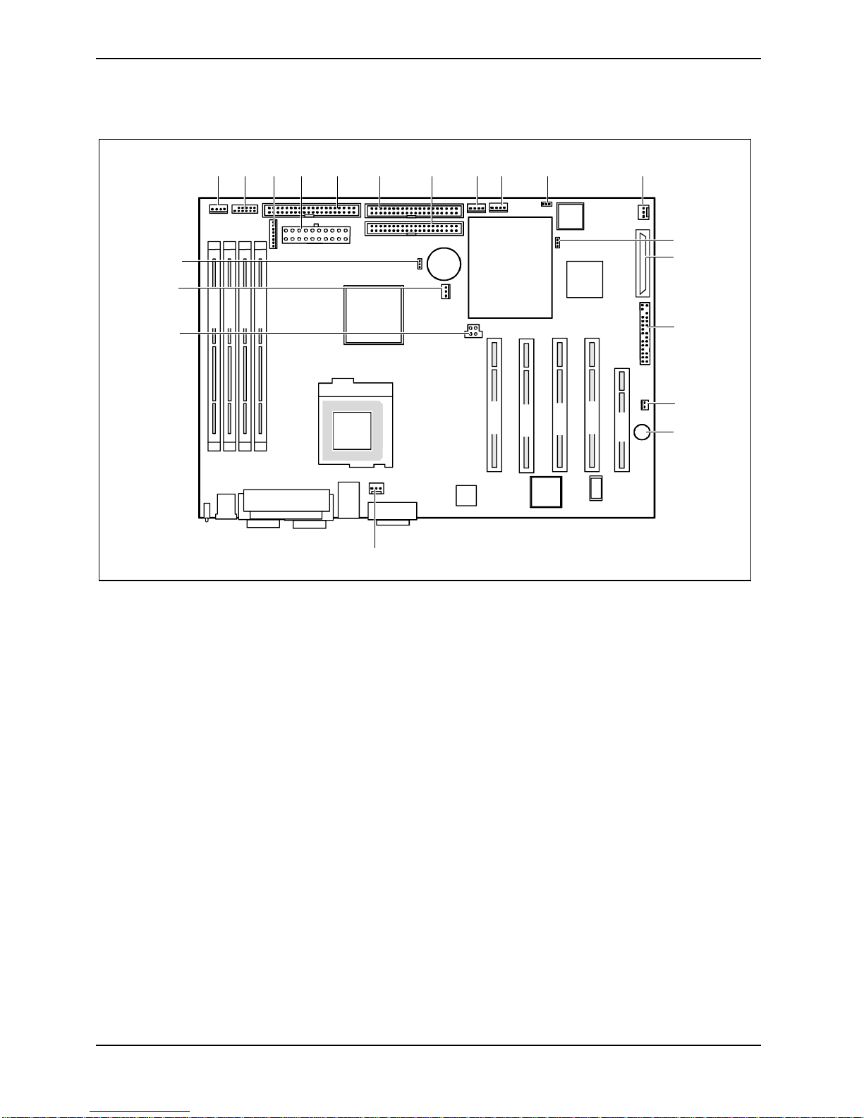
Internal ports and connectors
20
19
18
1
DIMM 3
DIMM 4
23
DIMM 1
DIMM 2
4
5
6
7
89
10
11
12
13
14
15
PCI 1
PCI 2
PCI 4
PCI 3
PCI 5
16
17
1 = SMBTerm
2 = USB ports
3 = Power supply monitoring
4 = Power supply ATX
5 = Floppy Disk Drive
6 = IDE drives 1 and 2 (primary)
7 = IDE drives 3 and 4 (secondary)
8 = IPMB
9 = SMB 1
10 = JP16
11 = Cover monitoring
12 = JP15
13 = SCSI connection
14 = Connector for front panel
15 = VCC_RSB (Remote Serv i ce Board)
16 = Buzzer
17 = System fan
18 = Power supply +12 V (for proc essor)
19 = Processor fan
20 = JP14
6 - English A26361-D1501-Z120-2-7419
Page 15

Features
Temperature / System monitoring
Temperature and system monitoring aim to reliably protect the computer hardware against damage
caused by overheating. However, unnecessary noi se is prevented with a fan speed adapted to the
temperature conditions. In addition, import ant information on the operating state of the devic e
(temperature, operating vol tate, fan speeds, error states) is provided. The cover monitoring system
indicates an unauthorized opening of the device.
These functions are controlled by the Baseboard m anagem ent controller.
The following functions are supported:
Temperature monitoring:
Measurement of the proc essor temperature, meas urem ent of the air temperature upon entry wi th a
temperature sensor.
Temperature control:
The fan speed of the system fan is controlled depending on the air temperature upon entry. When a
specified temperature limit is exceeded, the processor cl ock frequency is al so reduced (throttling
mode) to prevent further warm i ng of and damage to the processor.
Fan monitoring:
Blocked fans or a reduced fan speed due to ageing can be detec t ed with the fan monitoring
function. Blocked fans are operated with 12 V pul se voltage. An attem pt is made to restart a bl ocked
system fan with a cyclical voltage pulse. If the system fan is removed with the device switched off,
this results i n an error m essage when the device is switched on again. This is indicated opticall y by
the flashing of the system error LED on the control panel. In addition, an entry i s generated in the
BIOS Error Log.
Fan control:
The system fan and power supply fan are controlled in dependence on the temperature.
When exceeding predefined t em perature threshold the fanmotors in the power supply modules are
accelerated to maximale rotational speed.
Sensor monitoring:
The installed sensors are also monitored. If a sensor outputs an impermi ssible value, this results in
an increase in the fan s peed t o the maximum value in order to ensure the maximum pos sible
protection of the hardware.
A failed sensor resul ts in an error message. This is indicated optically by the flashing of the Health
LED on the control panel. In addition, an entry is generated in the BIOS Error Log.
Cover monitoring:
Unauthorised opening of the cover is detected, even when the system is switched off. However, this
will only be indicated when the system is switched on again.
This procedure generates an entry in the BIOS Error Log.
A26361-D1501-Z120-2-7419 English - 7
Page 16

Features
Voltage monitoring:
The operating voltages +5 V, +12 V, 3,3 V, 5 V the auxiliary voltage, the CPU core voltage and t he
CMOS-battery are monit ored.
If the voltage li es outside the specified tolerances, an error message is generated. This i s indicated
optically by the flashing of the Healt h LE D on the control panel. In addit i on, an entry is generated in
the BIOS Error Log.
Advantages of hardware system monitoring
With hardware monitoring - regardless of the operating system and processor - t he advantages
compared to conventi onal software monitoring are clear:
− suitable for all operating systems and processor types
− no additional load on processor (performance)
− optimum temperature protection, even if process faults or faults are present in the
operating system
− optimum noise reduction
IDE connector
Ê The system is equipped with two independent ATA/100 interfaces.
The Chip disk is alway s to be connected on the Pri m ary IDE connector.
The CD-ROM/DVD/CD-RW drive is to be connected on the Secondary IDE connector.
LAN connector
This mainboard has an Intel gi gabi t LAN controller ( This LA N controller supports the transfer rates
of 10 Mbit/s, 100 M bit/s and 1 Gbit/s. The LAN controller is equipped wi th a 3 KB transmission and
receiving buffer (FIF O) and supports WOL function t hrough M agi c Packetä.
In addition, Bootix LAN BootP and Intel PXE are also s upport ed (support of systems without hard
disks).
Basic AOL II i s also supported. Bas i c AOL II helps to prot ect systems against theft or damage.
Basic AOL II can also inform the administrator about hardware faults and software errors.
The LAN RJ45 connector is equipped with a yellow and a green LED (li ght emitting diode).
1 = Yellow indicator. a connec tion exists (e.g.
to a hub).
2
1
2 = Green indicator:
Link Mode: the LAN connection is active.
WOL mode: a Magic Packet
TM
is being
received.
8 - English A26361-D1501-Z120-2-7419
Page 17

PCI bus interrupts
The following table shows whi ch PCI bus interrupts are assigned on the mainboard.
Component on mainboard: PCI bus interrupt
PCI Slot 1 PCI_IRQ#7
PCI_IRQ#8
PCI Slot 2 PCI_IRQ#3
PCI_IRQ#4
PCI Slot 3 PCI_IRQ#5
PCI_IRQ#6
PCI Slot 4 PCI_IRQ#1
PCI_IRQ#2
PCI Slot 5 PCI_IRQ#7
PCI_IRQ#8
LAN controller 82540 PCI_IRQ#12
VGA-Rage XL PCI_IRQ#11
Onboard SCSI PCI_IRQ#0
SCSI/HostRAID configuration programme
Features
The BIOS of the Onboard U320 SCSI controller includes a menu-dri ven SCSI/HostRAI D
configuration programme. Thi s programme allows you to c hange al m ost all of the option s ettings of
the SCSI controll er.
When you boot the system a SCSI/HostRAID-BIOS message listing the SCSI devices connected i s
displayed.
If an SCSI-BI OS error message appears or problems arise with SCSI devices, please
i
Working with the keyboard
Use the following keys when running the programme:
ËÊ to select an entry
Ú to accept a selection
[ESC] to call the previous menu and to terminate the S CS I configuration programme.
[F6] to reset to the default settings. This function is not possible in all menus.
read the documentation of your SCSI device.
If you are unable to trac e or rectify the error, please contact your dealer or our c ustomer
service centre.
Starting the SCSI/HostRAID configuration programme
Ê Start the PC, if the following mess age appears, press the key combination [Ctrl] and [A] :
Press <Ctrl> <A> for SCSI Select (TM) Utility!
In the first menu the available U320 SCSI Control l er are di splayed. The onboard SCSI c ont rol l er of
D1501 is displayed with the following entry:
A26361-D1501-Z120-2-7419 English - 9
AIC-7901 at slot 00 00:04:00
Page 18

Features
When choosing the AIC-7901 you are taken to the top level of the configuration menu of this
controller. The followi ng options cannot be displayed.
HostRAID is disabled (default):
C
onfigure/View SCSI C ontroller Settings
SCSI Disk Utilities
Enable HostRAID Support
HostRAID is enabl ed:
C
onfigure/View SCSI C ontroller Settings
Configure/View HostRAID Settings
SCSI Disk Utilities
Disable HostRAID Support
Terminating the SCSI configuration programme
Depending on the current menu level , you can display t he previous menu by pressing the [ESC]
key. If you have made changes in the current menu you will be prompt ed to store them.
Ê To quit the Configuration programm e press the [ESC] key until a corresponding message is
displayed. Select Yes to quit.
Ê
Activating and Configurating Host RAID
To configurate HostRA ID select the menu entry Configure/View HostRA ID Settings. If this entry is
not displayed you hav e to activate HostRAID with the entry
Now the exsisting SCSI hard disks and alrady configurated RAID drives are di splayed.
Select one of the displayed hard diks and conf i gure the RAID-System to your needs.
Detailed instruction on the configuration of HostRAID are contained in the HostRAID
i
User's Guide.
The administration of the RAID system can be set later by a tool in your operating system
(see therefor the document ation "Storage Manager Browser E di tion"). this tool currently is
available for Windows NT4 and Windows 2000.
Enable HostRAID Support.
10 - English A26361-D1501-Z120-2-7419
Page 19

Features
Default Settings in the menu Configure/V iew SCSI Controller Settings
SCSI Bus Interface Definitions Default setting
SCSI Controller ID 7
SCSI Controller Pari t y Enabled
SCSI Controller Terminat i on Enabled
Additional Options Default setting
Boot Device Configuration Press <Enter>
Single Image
Master SCSI Control ler AIC-7901 at slot 00
00:04:00
Select SCSI peri pheral from which to boot
Boot SCSI Controll er AIC-7901 at slot 00
00:04:00
Boot SCSI ID 0
Boot LUN number* 0
SCSI Device Configuration Press <Enter>
Sync Transfer Rate (M B/Sec) 320
Packetized Yes
QAS Yes
Initiate wide negotiation Yes (Enabled)
Enable disconnect i on Yes (Enabled)
Send Start Unit Command**** Yes
BIOS Multiple LUN Support No
Include in BIOS Scan Yes
Advanced Configuration Press <Enter>
Reset SCSI Bus at IC Initialization Enabled
Display <Ctrl><A> Message During BIOS Init i al i zation Enabled
Extended Int 13 Transl at i on for DOS Drives > 1Gbyte Enabled
POST Display Mode Verbose
SCSI Controller Int 13 Support Enabled
Domain Validation**** Enabled
Support Removable Disks Under Int 13as
Fixed Disks****
BIOS Support for Boot able CD-ROM **** Enabled
* The setting is valid onl y if
**** The setting is valid only if t he I nt 13 Supportof the SCSI controller is enabled (
Multiple LUN Support is enabled (Enabled).
Disabled
Enabled).
A26361-D1501-Z120-2-7419 English - 11
Page 20

Features
SCSI Bus Interface Definitions
SCSI Controller ID
All SCSI devices on one SCSI bus, i ncluding the SCSI control ler, must be set t o separate SCSI
addresses.
The SCSI controller is normally set to ID 7.
You do not normally need to c hange the SCSI address, not even if you install several SCSI
controllers. In this case each SCS I controller may be assigned address 7, because each is
connected to it’s own SCSI bus.
SCSI Controller Parity
The U320-SCSI controller us es parity bits on t he S CS I bus to verify t he data transfer from your
SCSI bus (
If one of your SCSI devices does not support
SCSI Controller Termination
The terminating resis tors of the SCSI controller must be enabled.
Enabled).
Parity Checking, disable i t on the SCSI controller.
The default setting is Enabled. The terminating resistor of the SCSI c ont rol l er is enabled.
!
With [F6] you can reset to the default setting.
Additional Options
Master SCSI Controller
These settings di splay from which of the available SCSI control l er the BIOS is loaded. A s long as
the onboard SCSI controll er AIC-7901 is activ at ed, only this one is the master controller.
Boot SCSI Controller
This setting defi nes from which of the avai l abl e SCSI controller is boot ed.
Boot Target ID
The U320-SCSI controller c an start the operating system from a drive with any SCSI address (ID).
The default setting i s SCSI ID 0. The SCSI ID selected here must correspond to the ID configured
on the boot device.
Boot LUN number
If your boot device has multiple LUNs (Logical Unit Numbers) and Multiple LUN Support is Enabled,
this option allows you to specify which LUN to boot from on your boot dev i ce. The default sett i ng i s
LUN 0.
12 - English A26361-D1501-Z120-2-7419
Page 21

Features
SCSI Device Configuration
Sync Transfer Rate
Fast SCSI devices, including the U320-SCSI controller, are c apabl e of transferring data to and from
the SCSI bus at s peeds ranging up to 320 Mbyte/s at synchronous data trans f er. The configurable
maximum data transfer rate is 320 Mby te/s. For this s etting the options "Wide Negotiatin",
"Packatized" and "Disconnect i on" must be activated (YES).
Packetized
When activating the packetized option f or t he U320 SCSI operation not only dat a but also SCSI
commands and mess ages in synchronous operation are transferred. They are transferred together
with data in packages . With this more bus bandwidth
option is only for the U320 operation.
QAS
By the QAS (Quick Arbitration and Selec t ) option the packages are trans ferred on the SCSI bus
without a bus free phase bet ween the packages. As a result a higher throughput on the SCS I bus is
achieved. This option i s only for the U320 operation.
for real data transmission are available. Thi s
Initiate wide negotiation
This option determines whether the SCSI controll er at tempts 16-bit data transfer (Wide negotiation)
instead of 8-bit data transfer. As a resul t two byte are transferred simultaneously via the SCSI bus
instead of one byte.
Enable disconnection
The default setting is Yes (enabled).
This permits SCS I devices to enable the SCS I bus during command execution.
A typical ex am pl e of this is a tape devi ce that has no need to access the SCSI bus duri ng rewi ndi ng
and can be "disconnect ed" from the SCSI bus f or this period.
You can disable the function (
disabling disconnec tion improves performanc e slightly.
Send Start Unit Command
The default setting is Yes (enabled).
When this feature is enabl ed, the SCSI devices which support this function are not started by
switching on the se rver until they receiv e a " Start Unit" comm and f rom BIOS of the U320 SCSI
controller. (To do this the U320-SCSI controller B I OS must not be disabled).
This function ist used to distribut e the high starting currents of the SCSI devices over a specifi c
period and to release the power supply of your server.
BIOS Multiple LUN Support
This option determines whether booting from a SCSI dev i ce that has multiple LUNs (Logical Unit
Numbers) is supported. The def aul t setting is No (di sabled).
No) if you have only connected one SCSI device. In this case,
A26361-D1501-Z120-2-7419 English - 13
Page 22

Features
Include in BIOS Scan
With this setting it can be determined f or every SCSI address on t hi s SCSI bus, whether the SCSI
BIOS while initialisating checkes or not that a SCSI device with this special address is connected to
the bus. The default s et ting is Yes, i.e. the corresponding SCSI address is checked.
Advanced Configuration Options
Reset SCSI Bus at IC Initi alization
The default setting is Enabled.
This causes a reset on the SCSI bus during the i ni t i al i sation of the SCSI controller. All the devices
connected to the SCSI bus are reset and re-initialised by that.
Display <CTRL><A> Message During BIOS Ini ti al ization
This option determines whet her the
Press <Ctrl> <A> for SCSISelect (TM) Utility!
message appears on your s creen during system startup. The default setting is Enabled.
If this setting is disabled, you can still invoke the SCSI configuration programme by pressing [CTRL]
and [A] at system bootup.
Extended Int 13 Translation for DOS Drives > 1Gbyte
The default setting is Enabled.
Normally, only drives with a capacit y of up to 1 Gbyte can be accessed.
Enabling this option al l ows drives of up to 8 Gbyte capacity (2 Gbyt e/partition) to be supported
under MS-DOS 5.0 or higher.
The SCSI controller BIOS must be enabled. The driv e m ust be controlled by the S CS I controller
BIOS.
Back up the data on your l arge capacity drive bef ore enabl i ng the option.
i
After enabling this option, the drive must be re-partitioned and high-level
formatted with the DOS FDISK and FORMAT programmes.
Do not use this opti on wi th drives that cont ai n two or more partitions formatted with
different operating systems.
POST Display Mode
The default setting is Verbose.
While the system is booting, the SCSI controller's BIOS reports which devices are connected to the
SCSI bus. Further s et tings are Silent (no messages are s hown) and Diagnostic (additional
information are shown for di agnostics purposes).
14 - English A26361-D1501-Z120-2-7419
Page 23

Features
SCSI Controller Int 13 Support
The default setting for the Int 13 SCSI controller´s support is Enabled. With this the SCSI controller´s
BIOS is enabled.
If you are only running SCSI devices, from which you don´t want to boot and if you need space for
the BIOS of additi onal controller, then you dis abl e the Int 13 support of the U320-S CS I-controller.
When you disable the Int 13 support via the SCSI configuration programme, y ou can retain access
to the configuration programme at system start-up with the [Ctrl] - [A] keys.
Note under DOS that you will have to ins t all additional drivers to access driv es if the Int
i
Domain Validation
The default setting is Enabled.
The SCSI controller checks with a short test, whether the transmission rate set under Sync Transfer
Rate is possible. If errors occur, the transmission rate is reduced as far as no m ore errors occur.
Support Removable Disks under Int 13 as Fixed Di sks
This option allows you to use remov able-media dr iv es, such as CD-ROM drives, wit hout installing
additional drivers. The def aul t setting is Disabled.
13 support of the U320-SCSI controller is disabled.
If a removable-media dev i ce is controlled by t he SCSI controller BI OS , do not remove the
!
BIOS Support for Bootable CD-ROM
This option determines whether the BIOS supports a CD-ROM drive startup drive, i.e. you can bott
from CD-ROM. The default s etting is Enabled.
media while the PC is on.
A26361-D1501-Z120-2-7419 English - 15
Page 24

Features
SCSI Disk Utilities
When you select the SCSI Disk Utilities menu item, you are shown a list of all t he devices connected
to the SCSI bus. Y ou are al so offered two menus for hard disk drives: Verify and Format Disk.
Verify
With Verify you can have a selected hard disk drive checked. All defects that are detected will be
entered in the exist i ng error l i st for the hard disk.
Format Disk
With Format Disk a selected hard disk is formatted in low-level format. Normally hard disks are
already formatted in l ow-l evel format. You shoul d use this menu item only if you want to erase t he
hard disk complet el y and regenerate the error list.
16 - English A26361-D1501-Z120-2-7419
Page 25

Jumper settings
13
Jumper settings
The position of pin 1 in s creen process of the
mainboard is highlighted bold.
i
The clock frequency of the processor is set automatically.
Clear CMOS RAM - JP 14
The jumper JP14 allows you to delete the CMOS RA M.
1-2 Normal operation: The CM OS RAM is connected with the lithium battery (default
setting).
2-3 The CMOS RAM is deleted.
Boot Block - JP 15
The jumper JP15 enables recovery of the old system BIOS after an attempt to update has failed. To
restore the old system BIOS you need a Flash BIOS Diskette (please call our cus tomer service
centre).
1-2 The System is started with the system BIOS from the mainboard (default setting).
2-3 The system boots from the "Flash BIOS floppy dis k" from Drive A and reprograms
the system BIOS on the board.
BMC Power On Control - JP 16
The jumper JP16 allows the selection, by which chip the system start up is initiated and controled.
1-2 Power-on/off can only be controlled by the Baseboard Management Controller
(default setting).
2-3 Baseboard Management Controll e r and S uper I/O (BMC) can control Power-on/off.
A26361-D1501-Z120-2-7419 English - 17
Page 26
Add-on modules
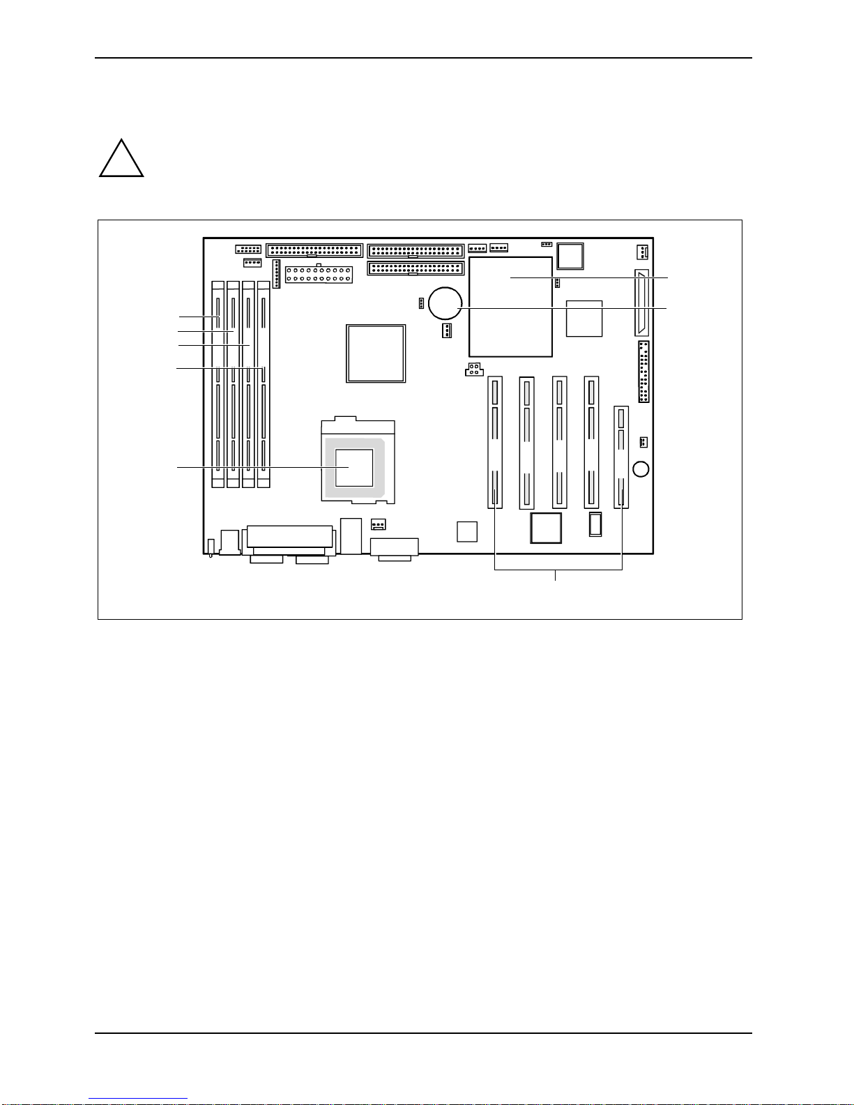
Add-on modules
Exit the operating system and wait until the device has s witched off. Pull the power plug
!
out of the mains outl et!
Even with the system switched off, certain parts of the device (e.g. memory modules and
PCI expansion boards) may s t ill be energised.
6
5
4
3
DIMM 4
DIMM 3
DIMM 2
DIMM 1
2
1
1 = Socket for processor with heat sink
2 = Location bank 1 for main memory
3 = Location bank 2 for main memory
4 = Location bank 3 for main memory
7
PCI 1
PCI 2
PCI 4
PCI 3
PCI 5
8
5 = Location bank 4 for main memory
6 = Baseboard management controller (B M C)
7 = Lithium battery
8 = PCI slots 1, 2, 3, 4, 5
The PCI slots 2-5 are supplied with 5 V main voltage, the PCI slot 1 with 3, 3 V. PCI slot 1 supports a
Zero Channel RAID Controller.
PCI slot 4 support s RSB (RSB = Remote Service Board) with battery package.
PCI slot 5 support s RSB without battery package.
18 - English A26361-D1501-Z120-2-7419
Page 27

Installing the processor with heat sink and fan
Ê Remove the heat sink i ncluding the fan fixed upon it.
2
3
3
1
1
2
4
4
Add-on modules
5
5
A
A
Ê Pull the lever in the direction of t he arrow (1) and lif t it as far as it will go (2).
Ê Remove the old processor from the socket (3).
Ê Insert the new proces sor in the socket s o that the angled corner of the proc essor matches the
coding on the socket (A) with regard to the position (4).
Push the lever back down until it clicks into place (5).
Mounting heat sink
If you are installing the heat sink you m ust ensure a good heat contact between heat sink and the
processor´s surf ace. It is essential to use heat conducting material between the processor and the
heat sink.
If you remove the heat sink, you must clean it (e.g. with benz i ne) and appl y new heat conducting
paste before you remount i t .
Please note that, dependi ng on the heat sink used, di f ferent heat sink mounts are required on the
mainboard.
Since a counter-plate i s mounted on the underside of the mainboard for reinforcement, no
i
heat sinks of t he type "Intel Boxed" may be used. Otherwise t he ret ai ni ng clips of the heat
sink will be damaged.
Only use the supplied heat sink and the supplied ret ai ni ng springs.
A26361-D1501-Z120-2-7419 English - 19
Page 28

Add-on modules
When using a new heat sink:
Ê Remove the protecti on cover from the
underside of the heat sink.
When using the previous heat sink:
Ê Apply an even coat of heat conducting paste
to the entire surfac e of the processor and
mount the heat sink on i t.
Ê Fix the heat sink wi th the supplied retaining
springs.
20 - English A26361-D1501-Z120-2-7419
Page 29

Add-on modules
Upgrading main memory
The slots for t he m ai n m em o ry are suitable for 256, 512, 1024 M byte unbuffered DDR-DIMM
memory modules.
Memory modules wit h di fferent memory capac i t ies can be combined.
You may only use unbuf f ered 3.3V memory modules. Buffered memory modules are not
!
Installing a memory module
allowed and lead to a device f ai l ure.
DIMM memory modules must meet the PC2100 specification.
2
2
Ê Push the holders on each side of the memory sl ot outwards.
Ê Push the memory modul e i nto the location (1).
Ê At the same tim e flip the both lateral holders upwards until the memory modul e snaps in
place (2).
Removing a memory module
1
1
Ê Push the clips on the right and left of the memory slot outward (1).
Pull the memory modul e out of the memory slot (2).
A26361-D1501-Z120-2-7419 English - 21
Page 30
Add-on modules
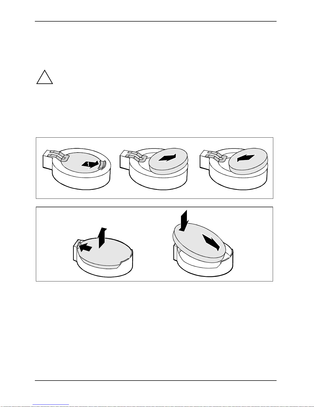
Replacing lithium battery
In order to permanently s ave the system information, a lithium battery is installed to provide the
CMOS-memory with a c urrent. A corresponding error mes sage notifies the user when the charge is
too low or the battery is empty. The lithi um bat tery must then be replac ed.
Incorrect replacem ent of the lithium batt ery may lead to a risk of explosion!
!
The lithium battery holder exists in dif ferent designs that function in the same way.
The lithium battery m ay be replaced only with an identical battery or with a t ype
recommended by the manufacturer.
Do not throw lithium batteries into the household waste. They must be disposed of in
accordance with loc al regul ations concerning special waste.
Make sure that you i nsert the battery the ri ght way round. The plus pole must be on the
top!
2
3
2
3
1
3
Ê Press the locking lug in the direction of the arrow (1); the battery jumps somewhat out of the
holder (2).
Ê Remove the battery (2).
Ê Insert a new lithium battery of the same t ype into the socket (3).
22 - English A26361-D1501-Z120-2-7419
Page 31

Glossary
Glossary
The technical terms and abbreviations given bel ow represent only a selecti on of the full list of
common technical terms and abbreviations .
Not all technical terms and abbreviations l i sted here are valid for the des cribed mainboard.
ACPI Advanced Configuration and
Power Management Interface
AC'97 Audio Codec '97 LAN Local Area Network
AGP Accelerated Graphic s Port LSA LA N Des k Service Agent
AMR Audio Modem Riser MCH Me m ory Controller Hub
AOL Alert On LAN MMX MultiMedia eXtension
APM A dvanced Power Management P64H PCI64 Hub
ATA Advanced Technology
Attachment
BIOS Basic Input Output System PXE Preboot eXecution Environment
CAN Controller Area Network RAM Random Access Mem ory
CPU Central Processing Unit RAMDAC Random Access M em ory Digital
CNR Communication Network Ri ser RDRAM Rambus Dynamic Random
C-RIMM Continuity Rambus I nline
Memory Module
DIMM Dual Inline Memory Module RTC Real Tim e Cl ock
ECC Error Correcting Code SB Soundblaster
EEPROM Electrical Erasable
Programmable Read Only
Memory
FDC Fl oppy disk controller SGRAM Sy nchronous Graphic Random
FIFO First-In First-Out
FSB Front Side Bus SIMD Streaming Mode Instruct i on
FWH Firm ware Hub SMBus System Managem ent Bus
GMCH Graphics and Memory Controller
Hub
GPA Graphics Performanc e
Accelerator
I2C Inter Integrated Circui t VGA Video Graphic Adapter
IAPC Instantly A vailable Power
Managed Desktop PC Desi gn
ICH I/O Controller Hub
IDE Intelligent Driv e E l ectronics
IPSEC Internet Protocol Security
ISA Industrial Standard Archi tecture
PCI Peripheral Component
Interconnect
Analogue Converter
Access Memory
RIMM Rambus Inli ne M em o ry Module
SDRAM Synchronous Dynamic Random
Access Memory
Access Memory
(Single Instruction Multiple Data)
SVGA Super Video Graphic Adapter
USB Uni versal Serial Bus
WOL Wake On LA N
A26361-D1501-Z120-2-7419 English - 23
Page 32

Information on this document
On April 1, 2009, Fujitsu became the sole owner of Fujitsu Siemens Computers. This new subsidiary of Fujitsu has been renamed Fujitsu Technology Solutions.
This document from the document archive refers to a product version which
was released a considerable time ago or which is no longer marketed.
Please note that all company references and copyrights in this document have
been legally transferred to Fujitsu Technology Solutions.
Contact and support addresses will now be offered by Fujitsu Technology Solutions and have the format …@ts.fujitsu.com.
The Internet pages of Fujitsu Technology Solutions are available at
http://ts.fujitsu.com/...
and the user documentation at http://manuals.ts.fujitsu.com.
Copyright Fujitsu Technology Solutions, 2009
Hinweise zum vorliegenden Dokument
Zum 1. April 2009 ist Fujitsu Siemens Computers in den alleinigen Besitz von
Fujitsu übergegangen. Diese neue Tochtergesellschaft von Fujitsu trägt seitdem den Namen Fujitsu Technology Solutions.
Das vorliegende Dokument aus dem Dokumentenarchiv bezieht sich auf eine
bereits vor längerer Zeit freigegebene oder nicht mehr im Vertrieb befindliche
Produktversion.
Bitte beachten Sie, dass alle Firmenbezüge und Copyrights im vorliegenden
Dokument rechtlich auf Fujitsu Technology Solutions übergegangen sind.
Kontakt- und Supportadressen werden nun von Fujitsu Technology Solutions
angeboten und haben die Form …@ts.fuji tsu.com.
Die Internetseiten von Fujitsu Technology Solutions finden Sie unter
http://de.ts.fujitsu.com/..., und unter http://manuals.ts.fujitsu.com finden Sie die
Benutzerdokumentation.
Copyright Fujitsu Technology Solutions, 2009
 Loading...