

Fujitsu Siemens Computers CELSIUS Mobile H240, Lifebook E8110, Lifebook E8210, CELSIUS H, LIFEBOOK E Series Easy Manual
...Page 1

Professional Notebook / Workstation English
EasyGuide
CELSIUS H
LIFEBOOK E Series
LIFEBOOK S Series
Page 2

Are there...
... any technical problems or other questions that you need help with?
Please contact:
• our Hotline/Help Desk (see the enclosed Help Desk List or the Internet:
"
www.fujitsu-siemens.com/s upport/"
• Your sales partner
• Your sales office
Additional information is contained in the Help Desk list and the "Warranty" manual. The
"Warranty" manual can be found on the "Drivers & Utilities" CD/DVD.
The latest information on our products, tips, updates, etc., can be found on
our website at: "
www.fujitsu-siemens.com"
Page 3

Page 4

This manual was produced by Xerox Global Services
Published by
Fujitsu Siemens Computers GmbH
AG 02/07
Edition 1
Order no.: A26391-K205-Z121-1-7619
Page 5

CELSIUS H / LIFEBOOK E Series /
LIFEBOOK S Series
Innovative technology… 1
Notational conventions
3
Important notes 4
Ports and operating elements
5
Removing and installing components
during servic
ing
22
Technical data
28
Index
34
EasyGuide
Page 6

Adobe and Acrobat are trademarks of Adobe systems I ncorporated and may
be protected in certain countries.
The Bluetooth trademarks are the property of Bluetooth SIG , Inc., U.S.A. licensed
for F ujitsu Siemens Computers GmbH.
Intel is a registered trademark, Core is trademark of Intel Corporation, USA.
Kensington and MicroSaver are registered trademarks of ACCO World Corporation.
Macrovision is a trademark of Macrovision Corporation, USA.
Microsoft, MS, MS-DOS, Windows, Windows NT and Windows Vista are registered
trademarks of Microsoft Corporation.
All other trademarks referenced are trademarks or registered trademarks of their
respective owners, whose protected rights are acknowledged.
Copyright © Fujitsu Siemens Computers GmbH 2007
All rights reserved, including rights of translation, reproduction by printing, copying
or similar methods, in part or in whole.
Offenders will be liable fo r damages.
All rights reserved, including rights created by patent grant or registration of a utility model or design.
Delivery subject to availability. Subject to technical alterations.
Page 7

Contents
Contents
Innovativetechnology… ............................................................... 1
Notationalconventions ................................................................ 3
Importantnotes ........................................................................ 4
Ports and operating elem
ents .........................................................
5
Frontview .............................................................................. 5
LIFEBOOK E Series/C E LS
IUSH ....................................................
5
LIFEBOOKSSeries ................................................................. 6
Rearview .............................................................................. 7
LIFEBOOKESeries/CEL
SIUSH .....................................................
7
LIFEBOOKSSeries ................................................................. 8
Underside . . . . .......................................................................... 8
LIFEBOOKESeries/
CELSIUSH .....................................................
8
LIFEBOOKSSeries ................................................................. 9
Switchingontheno
tebook . . . . ...........................................................
10
Switching off the
Notebook . . . ...........................................................
11
Status indicator
panel ...................................................................
12
Key combinations
.......................................................................
14
Easy Launch keys
......................................................................
16
Configuring Easy
Launch keys .......................................................
17
Removing and in
stallingthe battery .......................................................
17
Removing the b
attery ................................................................
17
Inserting the
battery .................................................................
18
SIMcard ............................................................................... 19
Inserting th
eSIM card ...............................................................
19
RemovingaSI
Mcard ...............................................................
20
Radio compon
ents:UMTS(optional)/wireless LAN/Bluetooth ...............................
21
Switching t
he radio components on and off ............................................
21
Removing and installing components during servicing .. . .............................. 22
Notesoninstallingandremovingboardsand components .................................. 22
Harddisk ............................................................................... 22
Removingtheharddisk .............................................................. 23
Installing the harddisk ............................................................... 24
Removingandinstallingmemorymodules ................................................ 25
Removingthecover ................................................................. 26
Removingmemorymodules .......................................................... 26
Installing amemory module .......................................................... 26
Attaching the cover .................................................................. 27
Techn
icaldata .........................................................................
28
Celsi
usH240 ...........................................................................
28
LIFEB
OOKE Series ....................................................................
29
LIFE
BOOKS7110 ......................................................................
31
Batt
ery .................................................................................
32
Main
s adapter ..........................................................................
33
Index .................................................................................. 34
A26391-K205-Z121-1-7619, edition 1
Page 8

Contents
A26391-K205-Z121-1-7619,edition1
Page 9

Innovative technology…
Innovative technology…
... and an ergonomic design make your notebook a reliable, convenient mobile PC.
This manual describes the CELSIUS H240 mobile workstation, the LIFEBOOK E8110,
the LIFEBOOK E8210 and the LIFEBOOK S7110. Most of the sections in this manual
apply to all models ‑ any differences are pointed out separately.
Your Windows operating system is alrea dy pre-installed and optimally configured. That means
you’re ready to start when you switch on your notebook for the first time.
Your notebook features the very latest technology so that you get the best performance from
your computing experience. Depending on which model you own, you have access to:
• Upto4Gbyteofmainmemory(RAM)
• A PC card slot for using a type I or type II PC card
• An ExpressCard slot for operating an ExpressCard/34 or ExpressCard/54
• A SIM card slot for using a SIM card (depending on model)
• An internal modem for connecting to the internet
• An S-Video Out socket for connecting your notebook to your television (for
LIFEBOOK S series, only with adapter)
• A FireWire port for connecting high speed devices such as digital camcorders
• A module bay for operating the following modules:
• Second battery
• Second hard disk drive
•DVD-ROMdrive
• Combo drive (CD-RW/DVD)
• Multi-format DVD burner with double layer support
• Weight Saver
• A touchpad and an additional TouchStick (optional).
• An audio controller, a built-in microphone and two internal speakers for true audio enjoyment.
• You can even connect an external microphone and external loudspeakers
to obta in an even better output level.
With the user-friendly BIOS-Setup you can control the hardware of your notebook and protect your
system better against unauthorised access by using the powerful password properties.
This o perating manual tells you how to put your notebook into operation
and how to operate it in daily use.
Further information on this notebook is provided:
• in the "Professional Notebook" operating instructions
• in the "Safety" a nd "Warranty" manuals
• in the "Wireless LAN" manual
• in the documentation of the operating system
•Intheinformationfiles (e.g. *.TXT, *.DOC, *.WRI, *.HLP, *.PDF)
A26391-K205-Z121-1-7619, edition 1 1
Page 10

Innovative technology…
You c a n find information on accessories for your notebook at
"
www.fujitsu-siemens.com/ accessories".
2 A26391-K205-Z121-1-7619, edition 1
Page 11
Notational conventions
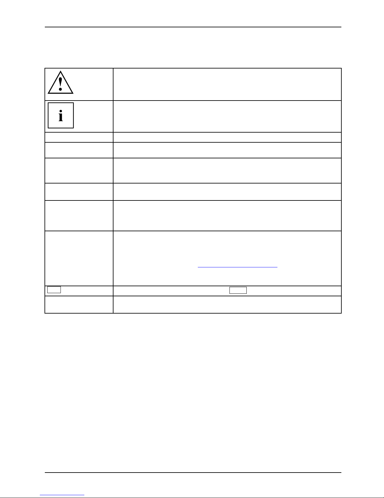
Notational conventions
Pay particular attention to text marked with this symbol. Failure to
observe this warning may endanger your health, cause the equipment to
malfunction or lead to loss of da ta. The warranty does not cover defects of
the equipment caused by failure to follow these instructions.
indicates important information that is required to use the device properly.
►
refers to an action which you must carry out.
indicates a result
This style
flags data entered using the keyboard in a program dialog or command
line, e.g. your password (Name123) or a command to launch a program
(start.exe)
This style
refers to information displayed by a program on the screen, e.g.:
Installation is completed
This style
is fo r
• terms and texts in a software user interface, e.g.: ClickSave.
• names of programs or files, e.g. Windows or setup.exe.
"This style"
is fo r
• cross-references to anot
her section, e.g. "Safety information"
• Cross-references to an external source, such as a web address: For
further information visit "
www.fujitsu-siemens.com"
• indicates names of CDs and
DVDs as well as names and titles of other
materials, e.g.: "CD/DVD
Drivers & Utilities" or "Safety" manual
Abc
refers to a key on the keyboard, e.g.:
F10
This style
flags concepts and text that are emphasised or highlighted, e.g.: Do not
switch off device
A26391-K205-Z121-1-7619, edition 1 3
Page 12

Important notes
Important notes
Take note of the safety hints provided in the "Safety" manual, in the "Professional
Notebook" operating manual and in this manual.
4 A26391-K205-Z121-1-7619, edition 1
Page 13
Ports and operating elements
Ports and operating elements
Ports
This chapter presents th e individual hardware components of your notebook. You can obtain
an overview of the ports and operating elements of the notebook. Please familiarise yourself
with these components before you start to work with your notebook.
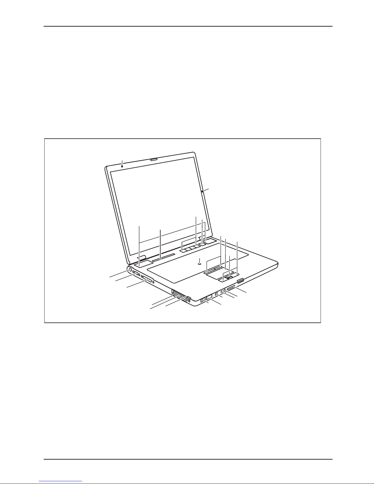
Front view
LIFEBOOK E Series/CELSIUS H
FrontViewBuilt-inmicrophone(dependingonmodel)Built-inmicrophone(depending onmodel)LoudspeakerStatusindicatorpanelEasyLaunchkeysON/OFFswitchTouchS tickTouchStickbuttonsTouch padScrollbarorfi ngerprintsensorTouchpadbuttonsMemorycardslotMicrophoneportHeadphonespo rtFireWirepor tON/OFFswitchforradiocomponents(WirelessLAN/Bluetooth/UMTS)Infraredint erfaceExpres sCardslotPCcardslotSmartCardreaderParallelportMonitorportDCINjack
1
2
3
4
5
6
7
8
10
11
12
13
14
15
16
17
18
19
20
9
21
22
23
1 = Built-in microphone (depending on model)
2 = Built-in microphone (depending on model)
3 = Loudspeaker
4 = Status indicator panel
5 = Easy Launch keys
6 = ON/OFF switch
7=TouchStick
8 = TouchStick buttons
9 = Touchpad
10 = Scroll bar or fingerprint sensor
11 = Touchpad buttons
12 = Memory card slot
13 = Microphone port
14 = Headphones port
15 = FireWire port
16 = ON/OFF switch for radio compon ents
(Wireless LAN/ Bluetooth/UMTS)
17 = Infrared interface
18 = ExpressCard slot
19 = PC card slot
20 = SmartCard reader
21 = Parallel port
22 = Monitor port
23=DCINjack
A26391-K205-Z121-1-7619, edition 1 5
Page 14

Ports and operating elements
LIFEBOOK S Series
FrontViewBuilt-inmicrophoneLoudspeakerStatusindicator panelEasyLaunchkeysON/OFFswitchTou chSt ickTouchStickbuttonsTou chpa dScrollbarorfingerprintsens orTouchpadbuttonsON/OFFswitchforradiocomponents(WirelessLAN/Bluetooth/UMTS)ExpressCardslotPCcards lotFireWireportHeadphonesportMicrophoneportSVideo Outsocket(minijac k)MonitorportDCINjack
1
2
3
4
5
6
7
8
10
11
12
13
14
15
18
19
9
16
17
1 = Built-in microphone
2 = Lou dspeaker
3 = Status indicator panel
4 = Easy Launch keys
5 = ON/OFF switch
6 = TouchStick
7 = TouchStick buttons
8 = Touchpad
9 = Scroll bar or fingerprint sensor
10 = Touchpad buttons
11 = ON/OFF switch fo r radio components
(Wireless LAN/ Bluetooth/UMTS)
12 = ExpressCard slot
13 = PC card slot
14 = FireWire port
15 = Headphones port
16 = Microphone port
17 = S Video Out socket (mini jack)
18 = Monitor port
19=DCINjack
6 A26391-K205-Z121-1-7619, edition 1
Page 15

Ports and operating elements
Rear view
LIFEBOOK E Series/CELSIUS H
KensingtonLockModemportModuleUSBportSerialportUSBportsKensingtonLockLAN po rtSVideoOutso cket(videoout
put)
1
2
3
4
5
6
7
8
9
1 = Kensington Lock
2 = M odem port
3 = M odule
4=USBport
5 = Serial port
6 = USB ports
7 = Kensington Lock
8 = LAN port
9 = S Video Out socket (video output)
A26391-K205-Z121-1-7619, edition 1 7
Page 16

Ports and operating elements
LIFEBOOK S Series
KensingtonLockModemportModuleUSBportInfraredinterfaceUSB portsKens in gtonLockLA N port
1
2
3
4
5
6
7
8
1 = Kensington Lock
2 = Modem port
3 = Module
4 = USB port
5 = Infrared interface
6 = USB ports
7 = Kensington Lock
8 = LAN port
Underside
LIFEBOOK E Series/CELSIUS H
BatteryPlugfordockingconnectionSlotformemoryexpansionHarddiskcompartment
1
2
3
4
1 = Battery
2 = Plug for docking connection
3 = Slot for memory expansion
4 = Hard disk compartment
8 A26391-K205-Z121-1-7619, edition 1
Page 17

Ports and operating elements
LIFEBOOK S Series
BatteryPlugfordockingconnectionSlotformemoryexpansionHarddiskcompartment
1
2
3
4
1 = Ba ttery
2 = Plug for docking connection
3 = Slot for memory expansion
4 = Hard disk compartment
A26391-K205-Z121-1-7619, edition 1 9
Page 18

Ports and operating elements
Switching on the notebook
1
2
► Press the release button (1), and unfold
the LCD screen upwards (2).
1
2
► Press the ON/OFF swit
ch (1) to switch
the n otebook on.
The power-on indicator of the notebook
appears in the status indicator panel (2).
Windows XP:
You can co n figure the on/off button under Start - (Settings) - Control Panel Performance and Maintenance - Power Options - Advanced.
Windows Vista:
You can configure the on/off button under Start - (Settings) - Control
Panel - Mobile PC - Power Options.
If you have assigned a password, you must enter this when requested to do so, in
order to start the operating system password. You can find more information in the
"Professional Notebook" operating instructions, "Security functions" section.
10 A26391-K205-Z121-1-7619, edition 1
Page 19

Ports and operating elements
Switching off the Notebook
► Close all programs and shut down your operating system (please see operating system manual).
If the notebook cannot be shut down properly, press and hold the ON/OFF button for
approximately four seconds. The notebook will switch off. Any unsaved data may be lost.
► Close the LCD screen so that it
locks into place.
A26391-K205-Z121-1-7619, edition 1 11
Page 20

Ports and operating elements
Status indicator panel
Statusindicatorpanel
The status indicator panel is a small LCD panel on which various symbols appear. Th ese symbols
provide information about the status of the power supply, the drives, and the keyboard functions.
Power-on indicator
CD/DVD indicator
Power indicator Hard disk indicator
Battery charging indicator
PC card/ExpressCard
indicators
First battery indicator Num Lock indicator
Second battery indicator Caps Lock indicator
Wireless LAN indicator
Scroll Lock indicator
The meanings of the symbols are as follows:
Power-on ind icato r
Power
-onindicator
Indic
ator
• Indicator lights up: The notebook is switched on.
• The indicator flashes (1 second on/ 1 second off). The notebook is in suspend
mode
• The indicator does not light up: The n otebook is switched off.
Power indicator
Pow
erindicator
Ind
icator
Indicator lights u p: The mains adapter is supplying power to the notebook.
12 A26391-K205-Z121-1-7619, edition 1
Page 21

Ports and operating elements
Battery charging indicator
BatterychargingindicatorIndicator
• Indicator lights up: The battery is charging.
• The indicator does not light up: The battery is either too hot or too cold to
be charged.
Battery indicators
IndicatorIndicatorBattery
The charging state of the batteries is shown by two battery indicators. 1 indicates
that the informa tion applies to the first battery in the battery compartment. 2
indicates that the information applies to th e second battery in the module bay.
indicates that the battery is 0 % to 25 % charged.
indicates that the battery is 25 % to 50 % charged.
indicates that the battery is 50 % to 75 % charged.
indicates that the battery is 75% to 100% charged.
Wireless LAN indicator
IndicatorWirelessLAN
• Indicator lights up: The wireless LAN module is switched on.
• Indicator flashes: The wireless LAN module is switched off.
CD/DVD indicator
IndicatorCD/DVDindicator
• Indicator lights up: The CD/DVD in the optical drive is being accessed. You
may only remove the CD/DVD when the indicator is dark.
• Indicator flashes: A CD/DVD is being inserted or removed.
Hard disk indicator
Harddiskindi
cator
Indicator
Indicator lights up: The hard disk drive of the notebook is being accessed.
PC card/ExpressCard indicators
IndicatorIndicatorPCCardExp ressCard
Indicator lights up: A PC card or an ExpressCard is being accessed.
Num Lock indicator
IndicatorNumLock
Indicator lights up: The
Num
key h as been pressed. The virtual numeric keypad is
activated. You can output the characters locat ed at the upper right on the keys.
Caps Lock indicator
IndicatorCapsLock
Indicator lights up: The Caps Lock key has been pressed. All the characters you
type appear in upper case. In the case of overlay keys, the character printed on the
upper left of the key appears when that key is pressed.
Scroll Lock indicator
IndicatorScrollL
ock
IndicatorRollLoc
k
Indicator lights up: The key combination
Fn
+
Rol
has been presse d. The effect
this key has varies from programme to programme.
A26391-K205-Z121-1-7619, edition 1 13
Page 22

Ports and operating elements
Key combinations
The following d escription of key combinations refers to functions when using
Microsoft Windows. Some of the following key combinations may not function in
other operating systems and with some device drivers.
Key combinations are entered as follows:
► Press and hold the first key in the combination.
► While holding the first key down, press the other key or keys in the combination.
The key combination
Ctrl
+
Alt Gr
or
Ctrl
+
Alt
canbeusedonexternal
keyboards that do not not feature a
Fn
key.
Enable/disable loudspeakers
Fn+F3LoudspeakersLoudspeakers
This key combination switches your notebook’s loudspeakers off and on.
An audible signal will be produced when the loudspeakers are switched on.
Enable/disable touchp ad
Fn+F4TouchpadLoudspeakers
This key combination enables and disables the touchpad.
Enlarge display
Fn+F5DisplayFull-screenmode
This key combination enlarges the screen to the full-screen mode or switches
it back to the normal mode.
Decrease screen brig htness
Fn+F6Screenbrightness
This key combination decreases the brightness of the screen.
Increase screen brightness
Fn+F7Screenbrightness
This key combination increases the brightness of the screen.
Decrease volume
Fn+F8Volume
This key combination reduces the volume of the integrated loudspeakers.
14 A26391-K205-Z121-1-7619, edition 1
Page 23

Ports and operating elements
Volume increase
Fn+F9Volume
This key combination raises the volume of the integrated loudspeakers.
Toggle output screen
Fn+F10Toggleoutput screen
If an external monitor is conn ected, the monitor on which the output is to be
displayed can be selected with this key combination.
You can opt to use:
• just the notebook’s LCD screen
• just the external monitor
• both the LCD screen and the external monitor
+
Strg
C
Halt current operation
Ctrl+C
This key combination can be used to hal
t an op eration instantly
without clearing the keyboard buff
er.
Switch between open applications
With this key combination you can switch between several open
applications.
Alt+Tab
AltCtrl
Del
SysRq
++
Performwarmboot
This key c ombination triggers a r
eset and reboots the notebook. First
press and hold both the
Ctrl
and
Alt
key,
then press the
Del
key. This will cause the Task Ma
nager to be displayed. The key
combinationmustbepresseda
second time to reboot the system.
Ctrl+Alt+DelWarmboot
Back tab
This key combination moves the cu
rsor back to the previous tabular
stop.
Shift+TabBacktab
Key combinations using the Windows keys are detailed in the manual
for your operating system.
A26391-K205-Z121-1-7619, edition 1 15
Page 24

Ports and operating elements
Easy Launch keys
EasyLaunchkeys
Your notebook is equipped with four Easy Launch keys.
12 R
E
Key 1
This key might be preset. However, you can also configure th is key as desired.
Key 2
This key might be preset. However, you can also configure th is key as desired.
E key
With the E key, yo u can easily activate and deactivate the energy saving functions (e.g.
reduce screen brightness), see "Professional Notebook" manual.
R key (recovery)
With the R key, you can restore the delivery status of your software installation or
set a restore point (snap-shot) in the recovery software.
Reset device to delivery status
All personal data will be deleted from your hard disk!
► Press the R key before the operating system starts.
The delivery status of yo
ur software installation is restored.
Set restore point in the recovery software
► Press the R key after the operating system has started.
A restore point is set in the recovery software.
Details are contained in the online help and in the documentation
for your recovery software.
16 A26391-K205-Z121-1-7619, edition 1
Page 25

Ports and operating elements
Configuring Easy Launch keys
With the Application Panel you can assign different functions to the Easy Launch keys.
Windows XP:
You wi l l find the Application Panel under Start - (settin gs) - Control Panel - Additional
Control Panel Options - Application Panel.
Windows Vista:
You will find the Application Panel under Start symbol - A ll Programs - Lifebook Application Panel.
Removing and installing the battery
NotesBattery
Only use batteries approved by Fujitsu Siemens Computers for your notebook.
Never use force when inserting or removing a battery.
Make sure that no foreign bodies get into the battery connections.
Removing the battery
► Switch the notebook off and pull the power plug out of the mains socket.
Battery
► Close the LCD screen so that it locks into place.
► Disconnect all cables conn ecte d to the notebook.
► Turn your notebook over and place it on a stable, flat and clean surface. If necessary, lay
an anti-slip cloth on this surface to prevent the notebook from being scratched.
2
1
3
► Slide the release button in the direction of
the arrow (1) and hold it in place.
► Slide the battery release latch in the
direction of the arrow (2) as far as it will go.
► Remove the battery from the battery
compartment (3).
A26391-K205-Z121-1-7619, edition 1 17
Page 26

Ports and operating elements
Inserting the battery
2
1
► Insert the battery in the battery compartment
at an angle and push it in the direction of
the arrow (1) until it locks into place.
Battery
► Push the battery release latch in
direction of the arrow (2).
18 A26391-K205-Z121-1-7619, edition 1
Page 27

Ports and operating elements
SIM card
Follow the instructions supplied by the provider of the SIM card.
Inserting the SIM card
► Switch off your notebook.
► Close the LCD screen so that i
t locks into place.
► Remove the mains plug for the mains adapter from the mains socket.
► Disconnect all cables conn ect
ed to the notebook.
► Turn your notebook over and place it on a stable, flat and clean surface. If necessary, lay
an anti-slip cloth on this surface to prevent the notebook from being scratched.
► Remove the battery (see Secti
on "
Removing the battery", Page 17).
1
2
► Slide the SIM card forwards in its slot with
the sloping corner at the front (1). T h e
chip should be facing upward.
► Slide the clip of the SIM card
in the
direction of the arrow (2).
► Reinstall the battery (see "
Inserting the battery", Page 18).
► Turn the notebook the right way up and place it on a flat surface.
► Reconnect the cables that you disconnected previously.
A26391-K205-Z121-1-7619, edition 1 19
Page 28

Ports and operating elements
Removing a SIM card
► Switch off your notebook.
► Close the LCD screen so that it locks into place.
► Remove the mains plug for the mains adapter from the mains socket.
► Disconnect all cables connected to the notebook.
► Turn your notebook over and place it on a stable, flat and clean surface. If necessa ry, lay
an anti-slip cloth on this surface to prevent the notebook from being scratched.
► Remove the battery (see Section "
Removing the battery", Page 17).
1
2
► Slide the clip of the SIM card in the
direction of the arrow (1).
► Push the edge of the SIM card to eject
it slightly from the slot.
► Pull the SIM card out of the slot in the
direction of the arrow (2).
► Reinstall the battery (see "
Inserting the battery", Page 18).
► Turn the notebook the rig
ht way up and place it on a flat surface.
► Reconnect the cables that you disconnected previously.
20 A26391-K205-Z121-1-7619, edition 1
Page 29

Ports and operating elements
Radio components: UMTS (optional)/wireless
LAN/Bluetooth
WirelessLANBluetoothUMTS
The installation of a wireless LAN or UMTS module not approved by Fujitsu Siemens
Computers GmbH will invalidate the permits (CE!, FCC) issued for this device.
The modules for radio c ompon ents are switched off during shipping.
Switching the radio components on and off
► Slide the ON/OFF switch into the "ON"
position to activate the radio components.
WirelessLANWireless LANBluetoothBluetooth
or
► Slide the ON/OFF switch into the
"OFF" position to deactivate the
radio components.
The Bluetooth and UMTS modules and the wireless LAN transmission unit (antenna)
will also be switched off when you switch off the radio components.
You can also deactivate the wireless components individually in the BIOS Setup.You
must have assigned the supervisor password in order for this function to be available.
Pay attention to the additional safety notes for devices with radio
components provided in the "Safety" manual.
Details on using wireless LAN are contained in the online help for your
wireless LAN software and in the "Wireless LAN" manual. (The "Wireless LAN"
manual can be found on the "Drivers & Utilities" CD/DVD.)
You ca n find more information on how to use Bluetooth on the CD you
received with your Bluetooth software.
You can obtain more information on UMTS from your service provider.
A26391-K205-Z121-1-7619, edition 1 21
Page 30

Removing and installing components
during servicing
Removing and installing compo
nents
during servicing
Only qualified technicians should repair your notebook. Un authorised
opening or incorrect repair may greatly endanger the user (electric shock,
fire risk) and will invalidate your warranty.
Components
Servicing
You may remove and install the components described in this chapter yourself
after consulting the Hotline/Help Desk.
If you remove and install components without consulting the Hotline/Help
Desk, then the warranty of your notebook will be voided.
Notes on installing and removing boards
and components
• Switch the notebook off an d pull the power plug out of the mains socket.
• Remove the battery.
• Take care when you use the locking mechanisms on the ba ttery and any other component.
• Never use sharp objects suc
h a s screwdrivers, scissors or knives as leverage to remove covers.
NotesBoardESD
Boards with electrostatic sensitive devices (ESD) are marked with the label
shown.
When handling boards fitted with ESDs, you must always observe the following
points:
• You must always discharge static build up (e.g. by touching a grounded
object) before working.
• The equipment and tools you use must be free of static charges.
• Remove the power plug from the mains supply before inserting or removing
boards containing ESDs.
• Always hold boards with ESDs by their edges.
• Never touch pins or c onductors on boards fitted with ESDs.
Hard disk
Harddi
sk
The hard disk is the most important storage medium of your notebook. You can work considerably
faster and more efficiently if you copy applications and files from CDs/DVDs to your hard disk.
When the hard disk is accessed, the drive indicator lights up.
22 A26391-K205-Z121-1-7619, edition 1
Page 31

Removing and installing components
during servicing
Removing the hard disk
► Switch your notebook off.
Harddisk
► Close the LCD screen.
► Unplug the mains plug of the mains adapter from the mains socket.
► Disconnect all cables connected to the notebook.
► Turn your notebook over and place it on a stable, flat and clean surface. If necessary, lay an
anti-slip cloth on this surface to prevent the notebook from being scratched .
► Remove the battery (see "
Removing the battery", Page 1 7).
2
1
1
3
LIFEBOOKESeries/CELSIUSH
1
1
2
3
LIFEBOOK S Series
► Remove the screws (1).
► Slide the cover of the hard disk compartment slightly forwards in the direction of the arrow (2)
and lift up to remove (3).
1
1
2
3
LIFEBOOKESeries/CELSIUSH
1
2
3
LIFEBOOK S Series
► Remove the screw/screws (1).
► Pull the hard disk as far as possible in the direction of the arrow (2) by the pulling aids .
► Lift the hard disk and remove it from the hard disk compartment in the direction of the arrow (3).
► Remove the hard disk from the hard disk carrier.
A26391-K205-Z121-1-7619, edition 1 23
Page 32

Removing and installing components
during servicing
Installing the hard disk
► Push the hard disk as far as possible in the hard disk carrier.
Harddisk
3
3
1
2
LIFEBOOK E Series/CELSIUS H
3
2
1
LIFEBOOK S Series
► Place the hard disk (1) into the hard disk compartment, flush with the left.
► Slide the hard disk as far as possible in the direction of the arrow (2) by the pulling aids.
► Secure the hard disk with the screw/screws (3).
2
3
3
1
LIFEBOOK E Series/CELSIUS H
2
1
3
3
LIFEBOOK S Series
► Place the cover of the hard disk compartment on the hard disk compartment so that a narrow
gap remains open (1).
► Slide the cover in the direction of the arrow (2) as far as it will go.
► Secure the cover with the screws (3).
► Install the battery again (see "
Inserting the battery", Page 18).
► Turn the notebook the right way up and place it on a flat surface.
► Reconnect the cables that you disconnected previously.
24 A26391-K205-Z121-1-7619, edition 1
Page 33

Removing and installing components
during servicing
Removing and installing memory
modules
MainmemoryMemoryexpansionMemoryupgradeSysteme xpan sion
The notebook will not start without memory modules, as no fixed main memory is installed.
Your notebook supports dual-channel DDR2 te chn o logy.
The dual-channel DDR2 technology can only be used with two identical
memory modules. When two different memory m odules are installed, only
"single-channel" performance is supported.
If you are asked by the Hotline/Help Desk to remove and install the memory
modules yourself, proceed as follows:
Pay attention to the relevant safety notes provided in the "Important notes" chapter.
The notebook must be switched off when installing/removing the memory
modules, it must not be in Suspend mode.
Only use approved memory expansion modules in your notebook
(see Section "
Technical da ta", Page 28).
Never use force when installing or remo ving memory modules.
Make sure that foreign objects do not fall into the m e m ory expansion compartment.
Individual components (e.g. the p
rocessor heat sink) can become very hot
during operation. Therefore, w
e recommend that you wait one hour after
switching off the notebook bef
ore removing or installing the memory modules.
Otherwise, there is a risk of su
ffering burns!
As some non-ESD safe component
s are exposed, please observe the section "
Notes
on installing and removing boa
rds and components", Page 22.
► Switch your notebook off.
► Fold the LCD screen down onto the bottom part of the notebook so that it locks into place .
► Unplug the mains adapter plug from the mains socket.
► Disconnect all cables conn ecte d to the notebook.
► Turn your notebook over and place it on a stable, flat and clean surface. If necessary, lay
an anti-slip cloth on this surface to prevent the notebook from being scratched.
► Removing the batt ery (see "
Removing the battery", Page 17).
A26391-K205-Z121-1-7619, edition 1 25
Page 34

Removing and installing components
during servicing
Removing the cover
1
1
2
► Remove the screws (1).
► Pull the cover off the notebook (2).
Removing memory modules
3
2
1
1
► Carefully push the two mounting
clips outwards (1).
MemoryexpansionMemorymodule
The memory module snaps upwards (2).
► Pull the memory module out of its slot
in the direction of the arrow (3).
Installing a
memory module
2
a
1
► Insert the memo ry module with the contacts
and the recess (a) f acing the slot (1).
Memorye
xpansion
Memorym
odule
► Carefully push
the memory module
downwards unti
l you feel it click
into place (2)
.
26 A26391-K205-Z121-1-7619, edition 1
Page 35

Removing and installing components
during servicing
Attaching the cover
2
2
1
► Place the cover in the correct
mounting position (1).
► Secure the cover with t h e screws (2).
► Reinstall the battery (see "
Inserting the battery", Page 18).
► Turn the notebook the right way up and place it on a flat surface.
► Reconnect the cables that you disconnected previously.
A26391-K205-Z121-1-7619, edition 1 27
Page 36

Technical data
Technical data
Celsius H240
Technicaldata
Processor
Intel Core™ Solo/Duo from 1.66 GHz
Main memory
Maximum 4 Gbyte DDR2 SDRAM
2 slots for 256, 512 Mbyte modules, 1 Gbyte or
2 Gbyte modules
Possible modules:
• Second battery
• Second hard disk drive
•DVD-ROMdrive
• Combo drive (CD-RW/DVD)
• Multi-format DVD burner with double layer
support
• Weight Saver
Electrical data
Regulations complied with
CE, CE!, Energy Star, EN60950
Protection class II
Maximum power draw (notebook on w
ith battery
charging)
80 W
LCD screen
Display diagonal
15 inch TFT WUXGA (1920 x 1200), 16 million
colours
Display adapter
Chip ATI Mobility FireGL V5200
Video memory (VRAM)
256 Mbytes
Audio
Soundchip ALC 262
Dimensions
Width x Depth x Height (front/b
ack)
360 mm x 259 mm x 35.5 mm
Weight with Weight Saver
approx. 2.6 kg
Input devices
Keyboard 85 keys
Touchpad/TouchStick 2 x 2 keys, 1 TouchStick
Slots
ExpressCard slot 1 x ExpressCard/34 or ExpressCard/5 4
PC card slot (CardBus/PCMCIA) PCMCIA 1 x type I or II
Memory card slot
1 x Secure Digital, 1 x MultiMedi
aCard, 1 x
MemoryStick or 1 x MemoryStick
Pro
28 A26391-K205-Z121-1-7619, edition 1
Page 37

Technical data
Ports
S Video Out s ocket
7-pin mini DIN socket
Monitor port 15-pin socket
Modem port RJ11 socket
LAN p ort RJ45 socket
Parallel port 25-pin socket
Serial port
9-pin plug
Microphone port 3.5 mm mono mini-jack
Headphones port/SPDIF
3.5mmstereominijack
FireWire port
S400, 4-pin
USB port 4 x USB 2.0
Infrared interface
IrDA 1.1
Docking connection 100-pin
Environmental conditions
Environment class (3K2) DIN IEC 721
Mechanical class 7M2
DIN IEC 721
Temperature
Operation 5 °C ... 35 °C
Transport
-15 °C ... 60 °C
LIFEBOOK E Series
Technicaldata
LIFEBOOK E8110 (internal graphics)
E8210 (internal and external
graphics)
Processor
Intel Core™ Solo/Duo from 1.66 GHz
Main memory
Maximum 4 Gbyte DDR2 SDRAM
2 slots for 256, 512 Mbyte modules, 1 Gbyte or 2 Gbyte modules
Possible modules
• Second battery
• Second hard disk drive
•DVD-ROMdrive
• Combo drive (CD-RW/DVD )
• Multi-format DVD burner with double layer support
• Weight Saver
Electrical data
Regulations complied with
CE, CE!, Energy Star, EN60950
Protection class II
Maximum power draw
(notebook on with battery
charging)
80 W
A26391-K205-Z121-1-7619, edition 1 29
Page 38

Technical data
LCD screen
Display diagonal
15 inch TFT XGA (1024 x 768)
15 inch TFT SXGA+
(1400 x 1050)
15.4 inch TFT WXGA
(1280 x 800)
15.4 inch TFT WXGA+
(1680 x 1050)
Display adapter
Chip Integrated Graphics Intel GMA
950
ATI MOBILITY™ RADEON®
X1400
Video memory (VRAM) Shared Memory
128 Mbyte
Audio
Soundchip ALC 262
Dimensions
Width x Depth x Height
(front/back)
360 mm x 259 mm x 35.5 mm 360 mm x 259 mm x 35.5 mm
Weight with Weight Saver
approx. 2 .6 kg approx. 2.6 kg
Input devices
Keyboard 85 keys
Touchpad/TouchStick 2 x 2 keys, 1 TouchStick
Slots
ExpressCard slot 1 x ExpressCard/34 or ExpressCard/5 4
PC card slot (CardBus/PCMCIA) PCMCIA 1 x type I or II
Memory card slot
1 x Secure Digital, 1 x MultiMed
iaCard, 1 x
MemoryStick or 1 x MemoryStic
kPro
Ports
SVideoOutsocket
7-pin mini DIN socket
Monitor port 15-pin socket
Modem port RJ11 socket
LAN port RJ45 socket
Parallel port 25-pin socket
Serial port
9-pin plug
Microphone port 3.5 mm mono mini-jack
Headphones port/SPDIF
3.5mmstereominijack
FireWire port
S400, 4-pin
USB port 4 x USB 2.0
Infrared interface
IrDA 1 . 1
Docking connection 100-pin
Environmental con dit ions
Environment class (3K2) DIN IEC 721
Mechanical class 7M2
DIN IEC 721
Temperature
30 A26391-K205-Z121-1-7619, edition 1
Page 39

Technical data
Environmental conditions
Operation 5 °C ... 35 °C
Transport
-15 °C ... 60 °C
LIFEBOOK S7110
Technicaldata
Processor
Intel Core™ Solo/Duo from 1.66 GHz
Main memory
Maximum 4 Gbyte DDR2 SDRAM
2 slots for 256, 512 Mbyte modules, 1 Gbyte or
2 Gbyte modules
Possible modules:
• Second battery
• Second hard disk drive
•DVD-ROMdrive
• Combo drive (CD-RW/DVD)
• Multi-format DVD burner with double layer
support
• Weight Saver
Electrical data
Regulations complied with
CE, CE!, Energy Star
Protection class II
Maximum power draw (notebook on with battery
charging)
80 W
LCD screen
Display diagonal
14.1 inch TFT XGA (1024 x 768)
14.1 inch TFT SXGA+ (1400 x 1050)
Display adapter
Chip Integrated Graphics Intel GMA 950
Video memory (VRAM) Shared Memory
Audio
Soundchip ALC 262
Dimensions
Width x Depth x Height (front/back)
306 mm x 248 mm x 33.5 mm
Weight with Weight Saver
approx. 1.8 kg
Input devices
Keyboard 85 keys
Touchpad/TouchStick 2 x 2 keys, 1 Touch Stick
Slots
ExpressCard slot 1 x ExpressCard/34 or ExpressCa
rd/54
PC card slot (CardBus/PCMCIA) PCMCIA 1 x type I or II
A26391-K205-Z121-1-7619, edition 1 31
Page 40

Technical data
Ports
SVideoOutsocket
Mini-Jack
Monitor port 15-pin socket
Modem port RJ11 socket
LAN port RJ45 socket
Microphone port 3.5 mm mono mini-jack
Headphones port/SPDIF
3.5mmstereominijack
FireWire port
S400, 4-pin
USB port 3 x USB 2.0
Infrared interface
IrDA 1 . 1
Docking connection 100-pin
Environmental con dit ions
Environment class (3K2) DIN IEC 721
Mechanical class 7M2
DIN IEC 721
Temperature
Operation 5 °C ... 35 °C
Transport
-15 °C ... 60 °C
The data sheet of this notebook
contains further technical data. You will find
the data sheet on your notebo
ok or on the Internet at "
www.fujitsu-siemens.com"
or on the supplied "Drivers &
Utilities" CD/DVD.
Battery
Technicalda
ta
CELSIUS H/
LIFEBOOK E
Series
LIFEBOOK S
Series
6-cell rechargeable battery 8-cell
rechargeable
battery
6-cell
rechargeable
battery
Rated voltage 10.8 V 14.4 V 10.8 V
Rated capacity 56.1 Wh 74.8 Wh 56.2 Wh
Charging time in the
switched-off state:
approx. 1.5 hours approx. 1.5 hours appro x. 1.5 hours
The operating time depends on the device configuration, the active
applications and the energy saving settings.
32 A26391-K205-Z121-1-7619, edition 1
Page 41

Technical data
Mains adapter
Technicaldata
Primary
Rated voltage
100 V or 240 V (automatic)
Rated frequency 50 Hz to 60 Hz (automatic)
Secondary
Rated voltage 19 V
Max. rated current 4.22 A
Additional mains adapters and an power cables are can be ordered at any time.
A26391-K205-Z121-1-7619, edition 1 33
Page 42

Index
Index
A
Alt+Tab 15
B
Back tab 15
Battery 8–9
important notes 17
indicator 1 3
inserting 18
removing 17
Battery charging indicator 13
Bluetooth 21
Switching off 21
Switching on 21
Board 22
Built-in microphone 6
Built-in microphone (depending on model) 5
C
Caps Lock
indicator 1 3
CD/DVD indicator 13
Components
installing / removing 22
Ctrl+Alt+Del 15
Ctrl+C 15
D
DC IN jack 5–6
Display
enlarge 14
E
Easy Launch keys 5–6, 16
ESD 22
ExpressCard
indicator 1 3
ExpressCard slot 5–6
F
FireWire port 5–6
Fn + F10 15
Fn + F3 14
Fn + F4 14
Fn + F5 14
Fn + F6 14
Fn + F7 14
Fn + F8 14
Fn + F9 15
Front 5–6
Full-screen mode 14
H
Hard disk 22
installing 24
removing 23
Hard disk compartment 8–9
Hard disk indicator 13
Headphones port 5–6
I
Indicator
Battery charging indicator 13
Caps Lock 13
CD/DVD 13
ExpressCard 13
First battery 13
Hard disk indicator 13
Num Lock 13
PC-Card 13
Power indicator 12
Power-on indicator 12
Roll Lock 13
Scroll Lock 13
Second battery 13
Wireless LAN 13
Infrared interface 5, 8
K
Kensington Lock 7–8
L
LAN port 7–8
Loudspeaker 5–6
Loudspeakers
disable 14
enable 14
M
Main memory 25
Memory card slot 5
Memory expansion 25
installing 26
removing 26
34 A26391-K205-Z121-1-7619, edition 1
Page 43

Index
Memory module
installing 26
removing 26
Memory upgrade 25
Microphone port 5–6
Modem port 7–8
Module 7–8
Monitor port 5–6
N
Notes
battery 17
boards 22
Num Lock
indicator 13
O
ON/OFF switch 5–6
ON/OFF switch for radio components 5–6
P
Parallel port 5
PC Card
indicator 13
PC card slot 5–6
Plug for docking connection 8–9
Ports 5
Power indicator 12
Power-on indicator 12
R
Roll Lock
indicator 13
S
S Video Out socket (mini jack) 6
S Video Out socket (video output) 7
Screen brightness
decrease 14
increase 14
Scroll bar or fingerprint sensor 5–6
Scroll Lock
indicator 13
Serial port 7
Servicing 22
Shift+Tab 15
Slot for memory expansion 8–9
SmartCard reader 5
Status indicator panel 5–6, 12
System expansion
memory expansion 25
T
Technical data
battery 32
Mains adapter 33
notebook 28–29, 31
Toggle output screen 15
Touchpad 5–6
disable 14
Touchpad buttons 5–6
TouchStick 5–6
TouchStick buttons 5–6
U
UMTS 21
USB port 7–8
USB ports 7–8
V
View
front 5–6
Volume
decrease 14
increase 15
W
Warm b oot 15
Wireless LAN 21
indicator 13
Switching off 21
Switching on 21
(Wireless LAN/ Bluetooth/UMTS) 5–6
A26391-K205-Z121-1-7619, edition 1 35
 Loading...