

Page 1
OPERATING MANUAL
OPERATING MANUAL
OPERATING MANUALOPERATING MANUAL
CELSIUS MOBILE
CELSIUS MOBILE 810
CELSIUS MOBILECELSIUS MOBILE
810
810 810
Page 2

Is there ...
r
... any technical problem or other
question you need clarified?
Please contact:
• one of our service partners
• your sales partne
• your sales outlet
The addresses of your service partners are contained in the guarantee booklet or in the service
address booklet.
The latest information on our products, tips, updates, etc., can be found on the Internet under:
http://www.fujitsu-siemens.com
Page 3

Page 4
Dieses Handbuch wurde auf Recycling-Papier gedruckt.
This manual has been printed on recycled paper.
Ce manuel est imprimé sur du papier recyclé.
Este manual ha sido impreso sobre papel reciclado.
Questo manuale è stato stampato su carta da riciclaggio.
Denna handbok är tryckt på recyclingpapper.
Dit handboek werd op recycling-papier gedrukt.
Herausgegeben von/Published by
Fujitsu Siemens Computers GmbH
A26391-K82-Z110-1-7619
Bestell-Nr./Order No.:
Printed in the Federal Republic of Germany
AG 0600 06/00
A26391-K82-Z110-1-7619
A26391-K82-Z110-1-7619A26391-K82-Z110-1-7619
A26391-K82-Z110-1-7619
Page 5

Introduction
Important notes
CELSIUS MOBILE 810
Operating Manual
Preparation for use and
operation
Troubleshootingand tips
Memoryextension
Connectingexternal
devices
Technical data
Index
June 2000 edition
Page 6

DPMS and VESA are registered trademarks of Video Electronics Standards Association.
Intel is a registered trademark, Pentium and Celeron are trademarks of Intel Corporation, USA.
Microsoft, MS, MS-DOS, Windows and Windows NT are registered trademarks of Microsoft
Corporation.
OS/2 and PS/2 are registered trademarks of International Business Machines, Inc.
Zip is a trademark of Iomega Corporation.
All other trademarks referenced are trademarks or registered trademarks of their respective owners,
whose protected rights are acknowledged.
Copyright ã Fujitsu Siemens Computers GmbH 2000
All rights, including rights of translation, reproduction by printing, copying or similar methods, even of
parts are reserved.
Offenders will be liable for damages.
All rights, including rights created by patent grant or registration of a utility model or design, are
reserved.
Delivery subject to availability. Right of technical modification reserved.
Page 7

Contents
Introduction .....................................................................................................................................1
Notational conventions ......................................................................................................................2
Installing an ergonomic video workstation .........................................................................................2
Important notes ...............................................................................................................................3
Safety................................................................................................................................................3
Notes on installing and removing boards...................................................................................3
Manufacturer’s notes.........................................................................................................................4
Energy saving............................................................................................................................4
Disposal and recycling...............................................................................................................4
CE certificate.....................................................................................................................................5
FCC Class B Compliance Statement.................................................................................................5
Power cord selection.........................................................................................................................6
For the United States and Canada.............................................................................................6
For the United Kingdom.............................................................................................................7
On the move with the workstation......................................................................................................7
Cleaning the workstation ...................................................................................................................8
Preparation for use and operation .................................................................................................9
Unpacking and checking the delivery ................................................................................................9
Selecting parking location..................................................................................................................9
Producing readiness for operation...................................................................................................10
Opening the workstation..........................................................................................................11
Removable infrared keyboard..................................................................................................11
Connecting infrared keyboard with cable.................................................................................13
Switching the workstation on...........................................................................................................14
Switching off the workstation...........................................................................................................15
Indicators and input devices............................................................................................................15
Display field.............................................................................................................................16
Touchpad and touchpad buttons..............................................................................................18
Keyboard.................................................................................................................................18
Key combinations....................................................................................................................20
Workstation battery..........................................................................................................................22
Charging, caring for and maintaining the workstation battery...................................................22
Learning cycle for workstation batteries...................................................................................24
Installing and removing workstation batteries and drives.........................................................25
Working with floppy disks ................................................................................................................27
Operating the CD-ROM drive and the DVD drive.............................................................................28
Zip drive ..........................................................................................................................................30
Installing the Iomega software.................................................................................................30
Operating the Zip drive............................................................................................................30
Handling Zip disks...................................................................................................................31
Manual removal (emergency removal).....................................................................................32
Chipcard reader...............................................................................................................................33
PC Cards.........................................................................................................................................33
Zoomed video port...................................................................................................................33
Installing a PC card .................................................................................................................34
Removing a PC card................................................................................................................34
Microphone and loudspeakers.........................................................................................................35
Using the power-management features...........................................................................................35
Maximum Power Savings ........................................................................................................36
Standby mode .........................................................................................................................36
Performance and Silence mode...............................................................................................36
A26391-K82-Z110-1-7619
Page 8

Contents
Suspend mode........................................................................................................................ 37
Decreasing reading speed of the CD-ROM drive..................................................................... 38
Display.................................................................................................................................... 38
Hard disk's energy saving function.......................................................................................... 38
Loudspeakers ......................................................................................................................... 38
Volume adjustment......................................................................................................................... 38
Changing display settings............................................................................................................... 39
Switching between internal and external screen...................................................................... 39
Troubleshooting and tips............................................................................................................. 41
The power-on indicator does not light up when the device is switched on....................................... 41
The workstation's display remains blank......................................................................................... 41
The workstation's display is difficult to read .................................................................................... 42
Defective pixels on the screen ........................................................................................................ 42
The external monitor stays blank .................................................................................................... 42
The external monitor is blank or the image is unstable.................................................................... 43
The screen display (TV) is black and white..................................................................................... 43
The workstation casing gets warm.................................................................................................. 43
The workstation stops working........................................................................................................ 43
The touchpad does not work........................................................................................................... 44
The mouse does not work............................................................................................................... 44
The infrared keyboard does not function when removed................................................................. 44
The floppy disk cannot be written.................................................................................................... 45
The workstation's date or time is incorrect ...................................................................................... 45
The printer does not print................................................................................................................ 45
Acoustic warnings........................................................................................................................... 45
Error messages on the screen........................................................................................................ 46
Memory extension ........................................................................................................................ 47
Connecting external devices........................................................................................................ 51
Ports............................................................................................................................................... 52
Connecting devices with serial or parallel port (printer)................................................................... 53
Connecting an external monitor ...................................................................................................... 53
Connecting the mouse.................................................................................................................... 53
Connecting a television set ............................................................................................................. 53
Connecting an external keyboard.................................................................................................... 54
Connecting external audio devices.................................................................................................. 54
Connecting the QuickPort............................................................................................................... 54
Transferring data with the infrared interface.................................................................................... 55
Technical data............................................................................................................................... 57
CELSIUS Mobile 810...................................................................................................................... 57
Workstation battery......................................................................................................................... 58
Power supply unit............................................................................................................................ 58
Car adapter..................................................................................................................................... 59
CD-ROM drive ................................................................................................................................59
DVD drive ....................................................................................................................................... 59
Chipcard reader.............................................................................................................................. 59
Interrupt I/O addresses, and DMA assignment................................................................................ 60
Port assignment.............................................................................................................................. 61
DC jack (DC IN)...................................................................................................................... 61
TV out socket.......................................................................................................................... 61
USB port................................................................................................................................. 61
Port for external keyboard and PS/2 mouse............................................................................ 62
Serial port ............................................................................................................................... 62
A26391-K82-Z110-1-7619
Page 9

Contents
Port for external monitor..........................................................................................................63
Parallel port.............................................................................................................................63
Index...............................................................................................................................................65
A26391-K82-Z110-1-7619
Page 10
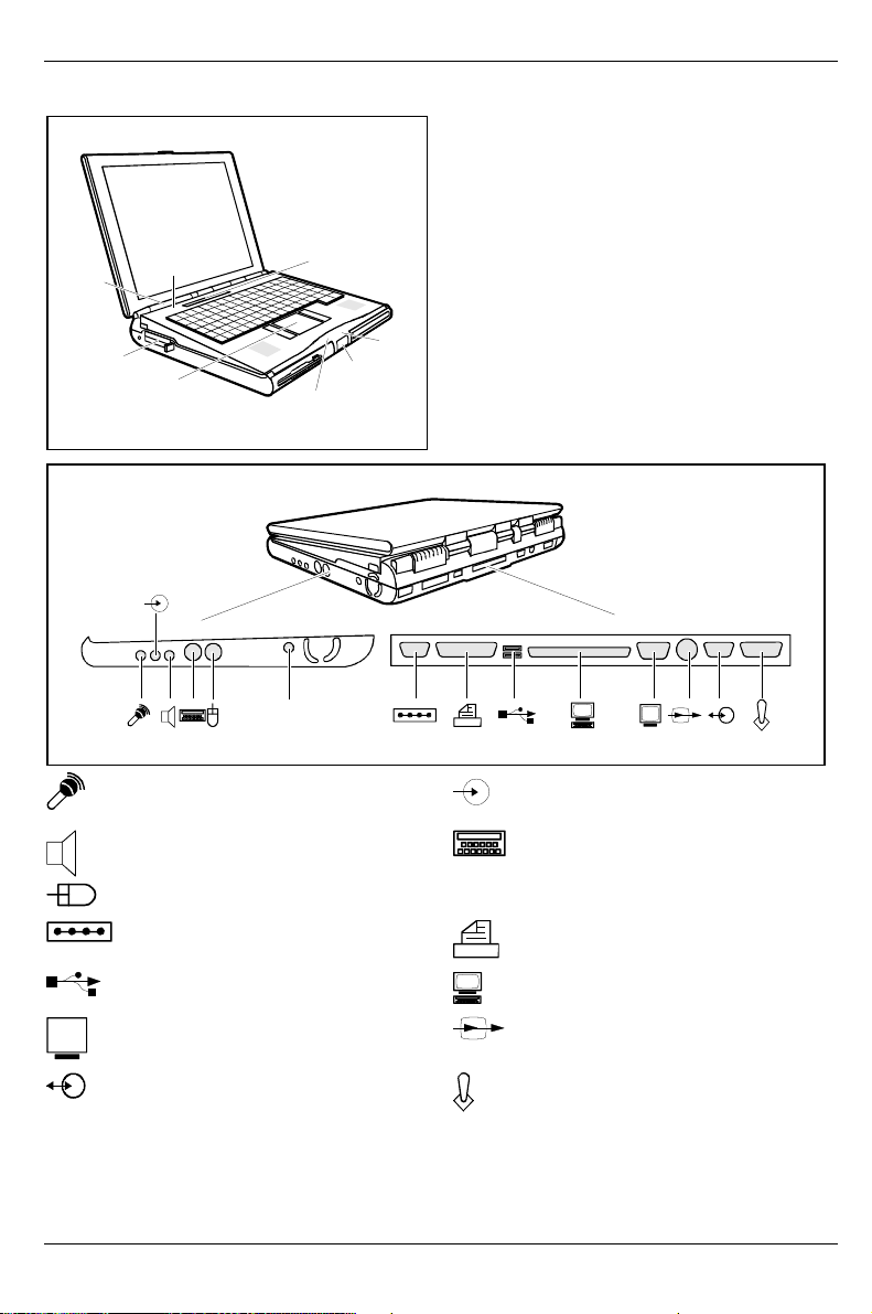
1 = ON/OFF switch
r
2 = PC card
3 = Touchpad and touchpad buttons
4 = Battery status indicator
5 = Release
6 = Power-on indicator
1
8
7
7 = Display field
8 = Microphone
2
3
DC-IN
Microphone jack
Audio output/loudspeake
4
6
5
Audio input (Line in)
PS/2 keyboard port
PS/2 mouse port DC IN DC socket
Serial port Parallel port
USB - Universal Serial Bus
Port for QuickPort S:
IR
Monitor port TV out
IR Port Game Port/MIDI Port
IR
A26391-K82-Z110-1-7619
Page 11

Introduction
Innovative technology and ergonomic design make this workstation the ideal user-friendly and
reliable travel companion. The removable keyboard now provides even more flexibility in the use of
your workstation. Your operating system is pre-installed on the hard disk to facilitate the procedure
when you use your workstation for the first time.
The energy-saving processor and the energy-saving functions that can be configured allow you to
make the most effective use of the battery capacity. By using an additional battery instead of the
disk drive, you can double the workstation's mobile operation time.
Your workstation has 64 -768 MB of main memory installed, depending on the upgrade level. Data is
stored on an Enhanced-IDE hard disk drive. Your workstation is supplied with both a 3 1/2" floppy
disk drive and a CD-ROM drive. In addition, your workstation can be equipped with a DVD drive, a
Zip drive or with a 2
simultaneous operation of two Type I/II/III PC cards (a maximum of one Type III and Type II each).
You can use the mouse supplied or your workstation's touchpad to control the mouse. A doubletouch directly on the touchpad is all that is required, for example, to open an application.
Your workstation has connectors for external devices such as, e. g. external monitor, television,
printer and mouse. The parallel port (which supports ECP and EPP modes) is designed to
accommodate bi-directional data transfer. You can connect peripherals such as, e. g. scanner,
loudspeakers, gamepads, keyboard or mouse via the USB interface. The workstation has a fast
IrDA interface for wireless data transfer. In addition, the workstation has a connection port for a
QuickPort S.
An audio controller, two built-in loudspeakers, a built-in microphone, an audio input and output
provide your workstation with an audio capability. You can also connect an external microphone,
external loudspeakers, a joystick or MIDI devices.
The system settings of the workstation can be configured via the user-friendly BIOS Setup program.
Certain system settings (e. g. screen display, energy saving functions) can be modified via various
key combinations while you are using the workstation.
Your workstation has a number of security features to ensure that no unauthorized persons can
access your data. As a result, access to your workstation is protected with a chipcard reader. The
security functions in the BIOS Setup also allow you to protect your data by means of passwords.
This Operating Manual tells you how to put your workstation into operation and how to operate it in
daily use.
Additional information on this workstation is also contained in:
• in the "Safety Notes" manual which is included with your workstation
• in the documentation of your operating system
• on the CD "Drivers & Utilities"
• in the information files (e. g. *.TXT, *.DOC, *.WRI, *.HLP)
• on the Internet at www.fsc-pc.de/drivercd/start.htm
nd
or 3rdhard disk drive. Two PC card slots (CardBus or PCMCIA) enable
Some of the manuals listed can be found on the CD "Drivers & Utilities" provided
with your computer. These manuals can be read and printed with the program
i
Acrobat Reader contained on the CD.
A26391-K82-Z110-1-7619 1
Page 12
Introduction Notational conventions
Notational conventions
The meanings of the symbols and fonts used in this manual are as follows:
Pay particular attention to texts marked with this symbol. Failure to observe this warning
endangers your life, destroys the workstation, or may lead to loss of data.
!
Supplementary information, remarks and tips follow this symbol.
i
Ê Texts which follow this symbol describe activities that must be performed in the order shown.
Texts in italics indicate commands or menu items.
"Quotation marks" indicate names of chapters and terms that are being emphasized.
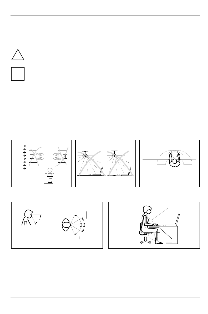
Installing an ergonomic video workstation
Before you set up your equipment you should select a suitable position for working at the monitor.
Please observe the following advices when installing a video workstation.
edge of desk
Window
permissible
reaching sector
600 mm
permissible
reaching sector
600 mm
Avoid direct and reflected glare. Avoid glare from electric
preferable viewing sector
0°
60°
permissible
viewing sector
permissible viewing sector
Position the monitor for optimum viewing. The
viewing distance to the monitor should be
approximately 50 cm.
2 A26391-K82-Z110-1-7619
lighting.
65°
30°
30°
65°
approx. 90°
more
Remember to maintain correct posture.
Position the keyboard where it
is easiest to reach.
approx. 90°
and
Page 13

Important notes
In this chapter you will find information regarding safety which it is essential to take note of when
working with your workstation. The manufacturer's notes contain helpful information on your
workstation.
Safety
Pay attention to the information provided in the manual "Safety Notes".
!
• During installation and before operating the device, please observe the instructions on
environmental conditions in the chapter entitled "Technical data" as well as the instructions in
the chapter "Preparation for use and operation".
• When cleaning the device, please observe the relevant notes in the paragraph "Cleaning the
workstation".
• Keep this Operating Manual together with your device. If you pass on the device to third
parties, you should include this manual.
Notes on installing and removing boards
Only qualified technicians should repair the device. Unauthorized opening or incorrect
repair may greatly endanger the user (electric shock, fire risk).
!
Boards with electrostatic sensitive devices (ESD) are identifiable by the
label shown.
When you handle boards fitted with ESDs, you must observe the following
points under all circumstances:
• You must always discharge yourself (e. g. by touching a grounded
object) before working.
• The equipment and tools you use must be free of static charges.
• Pull out the power plug before inserting or pulling out boards containing
ESDs.
• Always hold boards with ESDs by their edges.
• Never touch pins or conductors on boards fitted with ESDs.
A26391-K82-Z110-1-7619 3
Page 14

Important notes Manufacturer's notes
Manufacturer's notes
In normal screen mode (dark characters against a light background) the workstation satisfies the
ergonomic requirements for the GS symbol.
Energy saving
Make use of the device's energy saving functions (see "Preparation for use and operation").
• Switch the workstation off when you are not using it.
• The workstation uses less power when the power management features are enabled. You will
then be able to work for longer before having to recharge the battery.
Energy saving under Windows
If a monitor with energy saving features is connected to your workstation, you can use the Screen
Saver tab to set the energy saving features of the monitor. Select the following item in the menu:
Start - Settings - Control Panel - Display - Display Properties - Screen Saver - Energy saving features of
monitor. You can set additional energy saving functions in the start menu by selecting the following
item: Settings - System control - Energy - Extended .
Disposal and recycling
This device has been manufactured to the greatest possible degree from materials which can be
recycled or disposed of in a manner that is not environmentally damaging. The device is taken back
after use, to be recycled, provided that it is returned in a condition that is the result of normal use.
Any components not reclaimed will be disposed of in an environmentally acceptable manner.
For devices marked with this symbol Fujitsu Siemens Computers offers a
guarantee for 36 months with a Bring-in-Service. The guarantee starts on
the day of delivery (sale date) by Fujitsu Siemens Computers or a Fujitsu
Siemens partner.
We herewith declare that it will be possible to repair any device marked with
the eco-label for at least 5 years after production of that device has
discontinued.
Information on power management and energy saving mode can be found in
chapter "Technical data".
Do not throw lithium batteries or accumulators into the trashcan. They must be disposed of in
accordance with local regulations concerning special waste.
If you have any questions on disposal, please contact your local office, our customer service center,
or:
Fujitsu Siemens Computers GmbH
Frankfurterweg 60
Recyclingcenter
D-33106 Paderborn
Tel.: ..49 5251 818010
Fax: ..49 5251 818015
4 A26391-K82-Z110-1-7619
Page 15

CE certificate Important notes
CE certificate
The shipped version of this device complies with the requirements of the EEC directives
89/336/EEC "Electromagnetic compatibility" and 73/23/EEC "Low voltage directive".
FCC Class B Compliance Statement
If there is an FCC statement on the device, then:
The following statement applies to the products covered in this manual, unless otherwise specified
herein. The statement for other products will appear in the accompanying documentation.
NOTE:
This equipment has been tested and found to comply with the limits for a "Class B" digital device,
pursuant to Part 15 of the FCC rules and meets all requirements of the Canadian InterferenceCausing Equipment Regulations. These limits are designed to provide reasonable protection against
harmful interference in a residential installation. This equipment generates, uses and can radiate
radio frequency energy and, if not installed and used in strict accordance with the instructions, may
cause harmful interference to radio communications. However, there is no guarantee that
interference will not occur in a particular installation. If this equipment does cause harmful
interference to radio or television reception, which can be determined by turning the equipment off
and on, the user is encouraged to try to correct the interference by one or more of the following
measures:
• Reorient or relocate the receiving antenna.
• Increase the separation between equipment and the receiver.
• Connect the equipment into an outlet on a circuit different from that to which the receiver is
connected.
• Consult the dealer or an experienced radio/TV technician for help.
Fujitsu Siemens Computers GmbH is not responsible for any radio or television interference caused
by unauthorized modifications of this equipment or the substitution or attachment of connecting
cables and equipment other than those specified by Fujitsu Siemens Computers GmbH. The
correction of interference caused by such unauthorized modification, substitution or attachment will
be the responsibility of the user.
The use of shielded I/O cables is required when connecting this equipment to any and all optional
peripheral or host devices. Failure to do so may violate FCC rules.
A26391-K82-Z110-1-7619 5
Page 16
Important notes Power cord selection
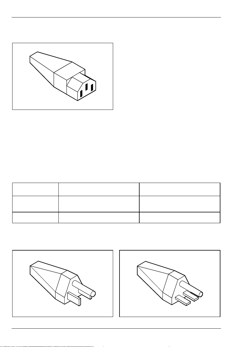
Power cord selection
The power cord for this unit has been packed
separately and has been selected for use in the
appropriate country. It must be used to prevent
electric shock. Use the following guidelines if it
is necessary to replace the original cord set.
The female receptacle of the cord set must meet
CEE-22 requirements (see Figure).
For the United States and Canada
Use a UL listed and CSA labeled cord set consisting of a three-conductor cord with a maximum
length of 15 feet.
For units that stand on a desk or table, type SVT or SJT cord sets shall be used.
For units that stand on floor, only SJT type cord sets shall be used.
The cord set must be selected according to the current rating for your unit. Please consult Table A
for the selection criteria for power cords used in the United States and Canada.
Table A:
Cord Type Size of Conductors
in Cord
SJT 18 AWG
16 AWG
14 AWG
SVT 18AWG
17 AWG
Maximum Current
Rating of Unit
10 Amps
12 Amps
12 Amps
10 Amps
12 Amps
For units set at 115 V:
use a parallel blade, grounding type attachment
plug rated 15 A, 125 V.
6 A26391-K82-Z110-1-7619
For units set at 230 V (domestic use):
use a tandem blade, grounding type attachment
plug rated 15 A, 250 V.
Page 17

On the move with the workstation Important notes
For units set at 230 V (outside of the United States and Canada):
use a cord set consisting of a minimum AWG according to Table A and a grounding type attachment
plug rated 15 A, 250 V. The cord set should have the appropriate safety approvals for the country in
which the equipment will be installed and should be marked HAR.
For the United Kingdom
Should the plug on the flexible cord not be of the type for your socket outlets, do not use an adapter
but remove the plug from the cord and discard. Carefully prepare the end of the supply cord and fit a
suitable plug.
WARNING
THIS APPLIANCE MUST BE EARTHED
IMPORTANT
The wires in this mains lead are colored in accordance with the following code:
Green and Yellow: Earth
Blue: Neutral
Brown: Live
As the colors of the wires in the mains lead of this appliance may not correspond with the colored
markings identifying the terminals in your plug, proceed as follows:
• The wire which is colored Green and Yellow must be connected to the terminal in the plug
which is marked with the letter E or by the earth symbol or colored Green or Green and Yellow.
• The wire which is colored Blue must be connected to the terminal which is marked with the
letter N or colored Black.
• The wire which is colored Brown must be connected to the terminal which is marked with the
letter L or colored Red.
On the move with the workstation
Please observe the points listed below when transporting your workstation.
Transporting the workstation
• Do not carry the workstation by its open screen or by an empty slot.
• Switch the workstation off and close the covers for the ports.
• Remove all data carriers (e. g. floppy disk, CD) from the drives.
• If it needs to be shipped, use the original packaging or other suitable packaging to protect it
from damage caused by mishandling.
• Protect the workstation from severe shocks and extreme temperatures (e. g., direct sunlight in
a car).
A26391-K82-Z110-1-7619 7
Page 18

Important notes Cleaning the workstation
r
Before starting the journey
• Save your data (Backup).
• Remove all data carriers (e. g. floppy disk, CD) from the drives.
• If you wish to use your workstation during a flight, check first with the flight attendants if it is
permissible to do so.
• If you are travelling abroad, ensure that the power adapter can be operated on the local line
voltage. If this is not the case, obtain the appropriate power adapter for your workstation.
Do not use any other voltage converter!
Cleaning the workstation
Switch the workstation off and pull the power plug of the power adapter out of the powe
socket.
!
Do not clean any interior parts yourself, leave this job to a service technician.
Do not use any cleaning agents that contain abrasives or may corrode plastic.
Ensure that no liquid enters the workstation.
Wipe the casing with a dry cloth. If particularly dirty, use a cloth which has been moistened in mild
domestic detergent and then carefully wrung out.
To clean the keyboard and the touchpad, you can use disinfectant wipes.
Wipe the monitor casing with a soft, moistened cloth.
8 A26391-K82-Z110-1-7619
Page 19

Preparation for use and operation
Please read the "Important notes" in the previous chapter.
!
You must charge the batteries of workstation and keyboard and install the application programs
before you can work with the workstation. The operating system and drivers required are
preinstalled.
When not plugged into a power outlet, the workstation runs on its built-in battery. You can increase
the battery's life by enabling the system's energy saving functions.
If you use the workstation in a normal office situation, you run it off the mains with the aid of the
power adapter, or in a QuickPort S.
The chapter on "Connecting external devices" has instructions on how to connect external devices
(e. g. mouse, printer) to the workstation.
Unpacking and checking the delivery
Ê Unpack all the individual parts.
Ê Check the delivery for damage incurred during transportation.
Ê Check whether the delivery agrees with the details in the delivery note.
Ê Check whether all necessary details have been entered on the first page of the guarantee
coupon booklet.
Should you discover that the delivery does not correspond to the delivery note, notify your local
sales outlet immediately.
Do not discard the original packing material of the devices. Keep it for future
transportation.
i
Selecting parking location
Select a suitable location for the workstation before setting it up. Consider the following points when
looking for a location.
• It is recommended that you place your workstation on a surface with good anti-slip qualities. In
view of the multitude of different finishes and varnishes used on furniture, it is possible that the
rubber feet of the workstation will mark the surface they stand on.
• Do not expose the workstation to extreme environmental conditions. Protect it from dust,
humidity and heat.
• Keep other objects 100 mm away from the workstation and its power adapter to ensure
adequate ventilation. The space between the workstation's feet must be clear.. Do not place
the workstation on a soft surface (e. g., a carpet or soft furnishings). Do not cover the
ventilation slots in the workstation and the power adapter.
• The power adapter must be at least 200 mm away from the workstation. It must be free-
standing and must not be covered. Do not place the power adapter on heat-sensitive material.
A26391-K82-Z110-1-7619 9
Page 20
Preparation for use and operation Producing readiness for operation
r
• For wireless data transfer you must align the workstation's IrDA interface with that of the
partner device (e. g. PC). The devices must not be more than one meter apart.
Producing readiness for operation
The power cord supplied conforms to the requirements of the country in which you
purchased your workstation. Make sure that the power cable is approved for use in the
!
country in which you intend to use it.
The workstation and the power adapter should be at least 200 mm apart. Keep othe
objects 100 mm clear of the workstation and its power adapter.
Do not cover the ventilation slots in the workstation and the power adapter.
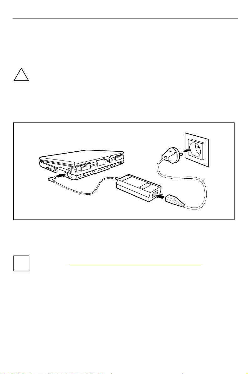
Ê Place the workstation on a flat, sturdy surface.
3
1
2
Ê Plug the DC output connector on the power adapter into the DC input connector (DC IN) on the
workstation (1).
Ê Connect the power cable to the power adapter (2).
Ê Plug the power cable into the power outlet (3).
You can also make your workstation operational by connecting it to the optional car
adapter (see "Charging, caring for and maintaining the workstation battery").
i
10 A26391-K82-Z110-1-7619
Page 21
Producing readiness for operation Preparation for use and operation
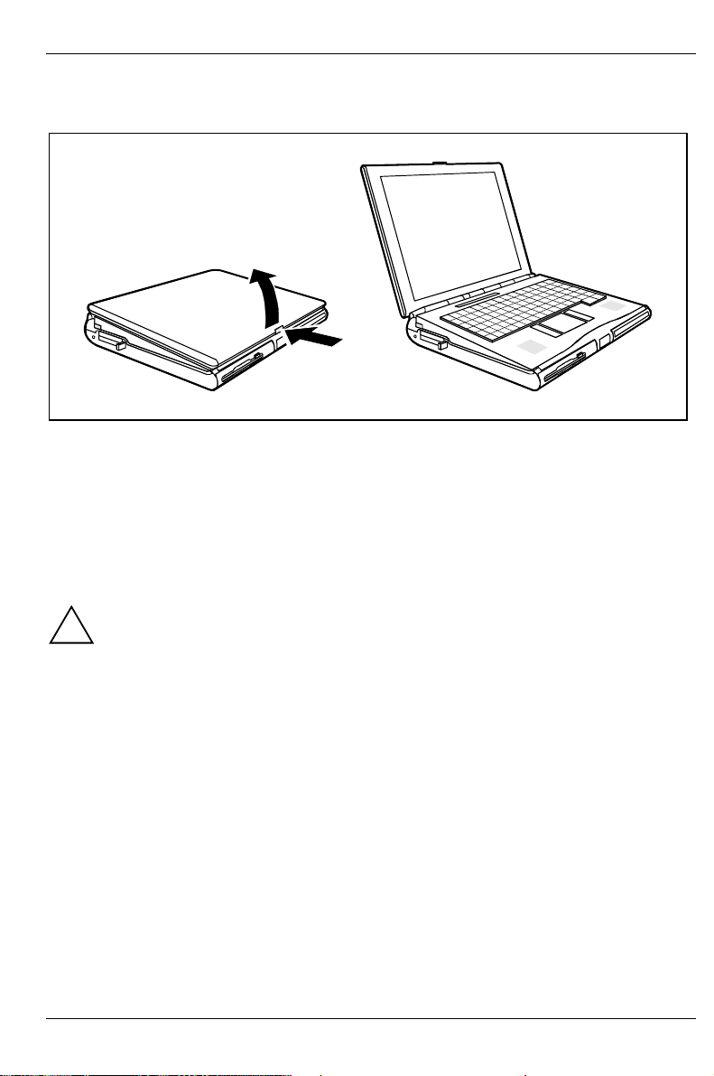
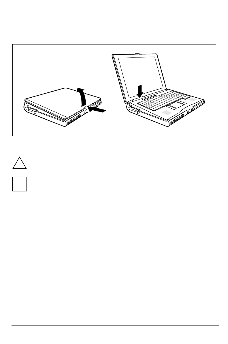
Opening the workstation
2
1
Ê Press the release button (1) and unfold the display upwards (2).
Removable infrared keyboard
The removable infrared keyboard now provides even more flexibility in the use of your workstation.
You can lift the keyboard off the workstation and operate it in front of the workstation. The
connection between the keyboard and the workstation is then via the IrDA interface on the back of
the keyboard and on the front of the workstation, as with a remote control unit. To operate the
keyboard separately from the workstation, the battery in the keyboard must be charged.
Charge the battery before initial use.
!
The battery in the keyboard is automatically charged when:
• the workstation is connected to the mains mode and
• the keyboard is installed and
• the workstation is switched off.
A26391-K82-Z110-1-7619 11
Page 22
Preparation for use and operation Producing readiness for operation
r
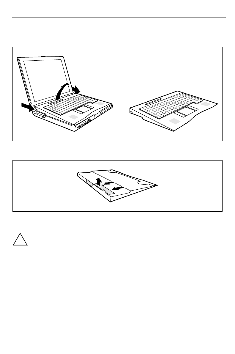
Installing keyboard battery
Ê Switch off the workstation.
1
2
3
1
Ê Push the locking slide forward (1).
Ê Lift the keyboard at the rear (2) and lay down the keyboard (3).
2
Ê Press the two tabs in the direction of the arrow (1).
Ê Lift the cover and pull it in the direction of the arrow (2) from the keyboard.
Use only the keyboard battery of the manufacturer.
!
The keyboard battery may only be charged with charging units approved by the
manufacturer for the workstation.
If you do not use the device for an extended period of time, remove the battery from the
keyboard.
Store the battery in a cool, dry place.
The keyboard battery must not be:
1
• short-circuited
• thrown into fire or heat
• thrown into wate
• exposed to rain or moisture
• opened
• loaded mechanically or damaged
12 A26391-K82-Z110-1-7619
Page 23

Producing readiness for operation Preparation for use and operation
Ê Plug in the plug of the keyboard battery.
Ê Lay in the keyboard battery.
Ê Close the cover.
2
1
1
Ê Place the keyboard in the lugs on the workstation (1) and press the keyboard into the bracket
provided until it is felt to engage (2).
Connecting infrared keyboard with cable
The infrared keyboard can be connected to a workstation or a PC with an optional cable. This
enables the keyboard and the touchpad to be used in the accustomed manner.
Ê Plug the round plug marked with the keyboard symbol into the keyboard connection and the
second round plug into the mouse connection of the PC.
Ê Plug the two square plugs into the back of the infrared keyboard.
A26391-K82-Z110-1-7619 13
Page 24
Preparation for use and operation Switching the workstation on
Switching the workstation on
3
2
1
Ê Press the release button (1) and unfold the display upwards (2).
Ê Press the ON/OFF switch (3) for roughly one second.
You must not switch off or warm-boot your workstation during this initial installation.
!
When you switch on your workstation for the first time the supplied software is set up and
configured. Please follow the instructions on the screen.
i
If you have assigned a password, you must enter this when requested to do so, in order to
start the operating system.
Once you have installed the operating system and have generally familiarized yourself
with the workstation, you should perform the battery learning cycle (see "Learning cycle
for workstation batteries").
Notes on Windows
The license number for Windows is printed on the front cover of the Windows manual supplied.
14 A26391-K82-Z110-1-7619
Page 25
Switching off the workstation Preparation for use and operation
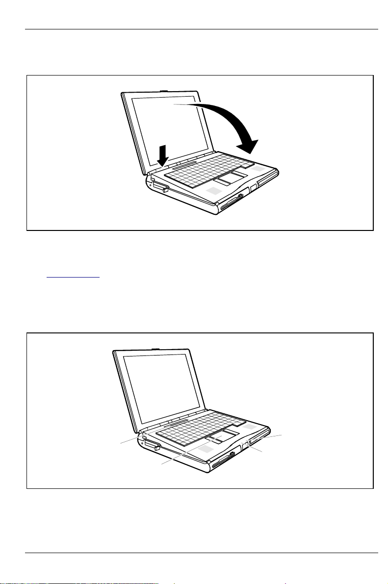
Switching off the workstation
2
1
Ê Shut down the operating system properly. The system is shut down and the workstation is
switched off. If the workstation is not switched off automatically, press the ON/OFF switch (1)
for approx. four seconds. If the ON/OFF switch is only pressed for approx. one second or the
monitor is folded closed, the workstation switches into the Suspend mode (see section
"Suspend mode").
Ê Close the display of the workstation (2) so that it is felt to lock into place centered.
Indicators and input devices
1
2
1 = Display field
2 = Touchpad and touchpad buttons
A26391-K82-Z110-1-7619 15
3 = Battery status indicator
4 = Power-on indicator
4
3
Page 26

Preparation for use and operation Indicators and input devices
K
]]]]
Battery status indicator
Glows green: Battery is being charged
Glows red: Battery capacity is below 12% or battery is defective
Power-on indicator
Glows green: Workstation is switched on
Display field
Symbols and texts in the display field indicate the operating state of the workstation. The meaning of
the symbols and texts are as follows:
%
The left battery is installed. When the symbol flashes, the left battery is drained or
defective (for measures, see "Charging, caring for and maintaining the workstation
battery").
The right battery is installed. When the symbol flashes, the right battery is drained or
defective (for measures, see "Charging, caring for and maintaining the workstation
battery").
%%
Indicates the approximate operating time of the installed batteries in percent.
Indicates the approximate operating time of the installed battery in hours and
h
minutes.
The arrow shows whether the battery is being charged or drained.
The workstation is connected to an external power source (e. g. via the power
adapter).
The workstation is switched to suspend mode.
The floppy disk in the floppy disk drive is being accessed. You must not remove the
floppy disk when this symbol is visible.
A drive (hard disk drive, CD-ROM drive, DVD drive or Zip drive) is being accessed.
When this symbol appears, do not remove the data carrier from the drive.
h
%
NumLk ScrLk
CapsLk
PadLk
IR
KB
CapsL
ScrLK The [SCROLL LOCK
16 A26391-K82-Z110-1-7619
All the characters you type appear in uppercase. In the case of overlay keys, the
character on the upper left on the keycap appears when that key is pressed. The
CapsLK indicator appears when you press the ÏÏÏÏ key.
[SCROLL LOCK
[SCROLL LOCK[SCROLL LOCK
program to program.
key has been pressed. The effect this key has varies from
Page 27

Indicators and input devices Preparation for use and operation
K
NumL
PadLK Thekey combination [Fn]
IR
KB
The [Pad Num]
[Pad Num] key has been pressed. If PadLK is also visible in the function
[Pad Num][Pad Num]
display, the blue numbers on the lower right on keys in the integrated numeric
keypad are enabled.
[Fn] + [Pad Num]
editing functions on the upper right on keys in the integrated numeric keypad.
The infrared connection between the removable keyboard and the workstation is
switched on. When this symbol flashes, the infrared connection is not sufficient.
Check the position of the removable keyboard relative to the workstation (see
"Removable infrared keyboard").
The "long-distance" infrared connection between the removable keyboard and the
workstation is switched on.
The remaining charge of the battery in the removable keyboard is not sufficient for
an infrared connection to the workstation. When this symbol flashes, install the
removable keyboard in the workstation. The battery will only be charged when the
workstation is operating in the mains mode.
The built-in loudspeakers are disabled.
The chipcard reader is active.
[Fn][Fn]
[Pad Num] has been pressed. This enables the blue
[Pad Num][Pad Num]
A26391-K82-Z110-1-7619 17
Page 28

Preparation for use and operation Indicators and input devices
Touchpad and touchpad buttons
Keep the touchpad clean, protect it from dirt, liquids or grease.
!
Do not use the touchpad if your fingers are dirty.
Do not rest heavy objects (e. g., books) on the touchpad or the touchpad buttons.
The touchpad enables you to move the mouse pointer on the screen. If, for example, you move one
finger to the left across the touchpad, the mouse pointer also moves to the left.
A brief tap with the finger on the touchpad has the same effect as clicking with the left mouse
button. A brief "double-tap" on the touchpad has the same effect as double-clicking with the left
mouse button.
The left and right touchpad buttons have the same functions as the left and right mouse buttons.
Keyboard
EscF1F2F3F4 F5F6F7F8 F9F10F11F12
~
!1@2#3$4%5^
`
Caps Lock
|
\
Ctrl
Fn
Standby
*
&
67890-
QW RTYUIOP{ }
E
7
(
8
456*
AZSXDCFVGBHNJ
123-
)
9
LCD/CRTCD slow LCDOff Suspend CPUslow InfoLCD TVon/off
_+
/
:"
MK<L>?
0
,. /
Alt Alt Gr Ins Del
.
SysRqPad Num
Lock
PrtScrn
=
[
]
,;
\
+
Scroll
Break
Lock
Pause
PgUp
Home
PgDn
The following description of keys and key combinations refers to Windows NT. Additional functions
supported by the keys are described in the relevant manuals supplied with your application
programs.
The figure below shows how to access the different characters on keys with overlaid functions. The
keystrokes shown in the example only work if CapsLK and PadLK have not been enabled (i.e. they
are not visible in the display field).
End
18 A26391-K82-Z110-1-7619
Page 29

Indicators and input devices Preparation for use and operation
y
y
7
7/{
7/{
Example from a German keyboard
Backspace ke
The Backspace key deletes the character to the left of the cursor.
Tab key
The Tab key moves the cursor to the next tab stop.
Enter key (return, enter, line feed, carriage return)
The enter key terminates a command line. The command you have entered is
executed when you press the key.
Caps Lock ke
The Caps Lock key activates uppercase mode (CapsLK is shown in the display
field). The Caps Lock function causes all the characters you type to appear in
uppercase. In the case of overlay keys, the character on the upper left on the
keycap appears when that key is pressed.
To cancel the Caps Lock function, simply press the Caps Lock key again.
Shift key
The Shift key causes uppercase characters to appear. In the case of overlay keys,
the character on the upper left on the keycap appears when that key is pressed.
Alt Gr
Fn
Alt Gr key
The [Alt Gr]
[Alt Gr] key causes the characters in the lower middle of the keycap to appear
[Alt Gr][Alt Gr]
(e.g. { in the case of the [7]
Fn key
The [Fn]
[Fn] key enables the special functions indicated in blue on overlay keys (see
[Fn][Fn]
"Key combinations").
If the external keyboard does not feature a [Fn]
the [Ctrl]
[Ctrl] + [Alt]
[Ctrl][Ctrl]
Cursor keys
The cursor keys move the cursor in the direction of the arrow, i.e., up, down, left, or
right.
7
[Alt] keys instead.
[Alt][Alt]
7/{
Alt Gr
7
7
7/{
[7] key on the German keyboard).
[7][7]
NumLk
[Fn] key, you can simultaneously press
[Fn][Fn]
Fn
7/{
7
A26391-K82-Z110-1-7619 19
Page 30

Preparation for use and operation Indicators and input devices
Pad Num
Lock
Pad Num key
When the numeric keypad is enabled (PadLK is visible in the display field), the [Pad
Num]
Num] key causes this set of keys to produce numbers (NumLK appears in the
Num]Num]
display field). Pressing them produces the blue characters shown on the bottom
right on the keycaps.
Break
Pause
Pause key
The [Pause]
[Pause] key temporarily suspends display output. Output will resume when you
[Pause][Pause]
press any other key.
Start key
The Start key invokes the START menu of Windows.
Menu button
The Menu key invokes the menu for the marked item.
%
5
,
Euro key
$
The Euro key enables the entering of the euro symbol.
4
Numeric keypad
&*( )
7890
789 /
UI OP
456*
12
J
K
L
:
123-
0+,
M
<
,. /
;
>?
[Pad
[Pad[Pad
1 = Characters enabled when neither PadLK nor NumLK are visible in the display field.
2 = Characters enabled when PadLK and NumLK are visible in the display field.
The key [Pad Num]
enabled (NumLK is shown in the display field) and you hold the [Fn]
[Pad Num] enables and disables the integrated numeric keypad. If the numeric keypad is
[Pad Num][Pad Num]
[Fn] key down, you can output the
[Fn][Fn]
characters printed in blue at the right bottom of the keys.
When the numeric keypad is enabled (NumLK is visible in the display field), pressing the key
combination [Fn]
[Fn] + [Pad Num]
[Pad Num] enables and disables the numeric entry in the integrated numeric
[Fn][Fn]
[Pad Num][Pad Num]
keypad. If numeric entry is enabled (NumLK and PadLK are shown in the display field), the blue
characters at the bottom right of the keys are effective.
Key combinations
The following description of key combinations refers to functions when using Microsoft Windows NT.
Some of the following key combinations may not function in other operating systems and with some
device drivers. Other key combinations are described in the relevant manuals supplied with your
application programs.
20 A26391-K82-Z110-1-7619
Page 31

Indicators and input devices Preparation for use and operation
j
j
You enter key combinations as follows:
Ê Press and hold the first key in the combination.
Ê While keeping the first key pressed, press the other key or keys in the combination.
If the external keyboard does not feature a [Fn]
[Ctrl]
[Ctrl] + [Alt]
[Alt] keys instead.
[Ctrl][Ctrl]
F1
LCDOf f
[Alt][Alt]
Switching monitor on/off
This key combination switches your workstation's display on and off. Doing so
i
Fn
+
[Fn] key, you can simultaneously press the
[Fn][Fn]
does not affect any running programs.
Fn
F3
+
Standby
Enabling Standby mode
This key combination enables Standby mode. You can cancel Standby mode by
pressing any key.
Fn
F4
+
Suspend
Enabling Suspend mode
This key combination switches the system into Suspend mode (see Section
"Suspend mode "). When you switch the workstation on again, the system
returns to where it was and the active programs continue running from where
they were when you switched into Suspend mode.
Fn
Fn
Fn
Fn
F6
+
F7
+
F8
+
F10
+
InfoLCD
Switching the loudspeaker on/off
This key combination switches the integrated loudspeaker on and off.
Increasing the volume
This key combination raises the volume of the integrated loudspeaker.
Reducing the volume
This key combination decreases the volume of the integrated loudspeaker.
Switching over battery indicator
This key combination switches the battery indicator in the display field between
battery capacity in %, as time (workstation will still run xx:xx hours) or the
battery charging level display.
Fn
F11
+
TVo n/of f
Switching TV out on/off
This key combination switches the video output (TV out) on or off.
Fn
F12
+
LCD/CRT
Switching between internal and external screen
If an external monitor is connected, this key combination switches off the screen
display. You can opt to use:
•
ust the workstation's internal display
•
ust the external display
•
• both the internal and the external display.
• •
Increasing the display brightness
Fn
+
This key combination increases the brightness of the display.
Reducing the display brightness
Fn
+
A26391-K82-Z110-1-7619 21
This key combination reduces the brightness of the display.
Page 32

Preparation for use and operation Workstation battery
Workstation battery
The workstation is fitted with a battery (Lithium Ion battery) that provides it with power during mobile
use. You can increase battery life by enabling the system's power management features.
In addition to the workstation standard battery, you can also use a second workstation battery. By
using both workstation batteries, you can double the workstation's mobile operation time.
The workstation battery charge is indicated by the battery symbol in the display field (see chapter
"Indicators and input devices"). When you switch on the workstation, it takes a few seconds before
the battery status is displayed.
The battery will last for roughly 500 charge/discharge cycles.
To utilize the optimum charging capacity of the battery, you should regularly perform the
battery learning cycle (see chapter "Learning cycle for workstation batteries").
i
Charging, caring for and maintaining the workstation battery
Only use workstation batteries designed for this workstation.
!
The workstation battery can only be charged, when the ambient temperature is between 5°C and
max. 40°C.
The workstation battery charge is indicated by the battery symbol in the display field.
A workstation battery will fully charge in approximately three hours in a workstation that is switched
off. After half the charging time, the battery has already reached a 70 % charge level. A workstation
battery will fully charge in approximately four hours if the workstation is switched on. If the
workstation is fitted with two workstation batteries, charging will take twice as long. The workstation
batteries are charged successively. The battery which was connected first is charged first.
The workstation battery can be charged by:
• connecting the workstation to the power adapter
• connecting the workstation to the car adapter
• connecting the workstation to the QuickPort S
Before a workstation battery is used for the first time, the battery learning cycle should be performed
(see also the section "Learning cycle for workstation batteries").
Work in the battery mode until an acoustic warning signal indicates the need for charging. The
workstation battery should not be charged before this point.
If you do not use the workstation batteries for an extended period of time, remove them
from the workstation. Never store the workstation batteries in the unit.
i
If storing for a long period of time (longer than two months), workstation batteries should be stored
in a charged state of approximately 50%. After six months, at the latest, you should run a learning
cycle with the batteries again. If you store the batteries up to two months, the charge status of the
batteries must be approximately 30%. The workstation batteries should be stored in a dry
environment in temperatures between +10°C and +25°C.
22 A26391-K82-Z110-1-7619
Page 33

Workstation battery Preparation for use and operation
r
Connecting the power adapter
The power cable corresponds to the country version of the workstation. Make sure that the
power cable is approved for use in the country in which you intend to use it.
!
The workstation and the power adapter should be at least 200 mm apart. Keep othe
objects 100 mm clear of the workstation and its power adapter. Do not cover the
ventilation slots in the workstation and the power adapter.
Do not place the power adapter on heat-sensitive material.
The power adapter's AC cord should only be connected to a wall outlet if the workstation
is connected to the power adapter.
Ê Place the workstation on a flat, sturdy surface.
Ê Install the battery.
3
1
2
Ê Plug the DC output connector on the power adapter into the DC input connector (DC IN) on the
workstation (1).
Ê Connect the power cable to the power adapter (2).
Ê Plug the power cable into the power outlet (3).
The power adapter indicator lights up. After a few seconds the workstation's battery status
indicator lights up. The battery will charge.
A26391-K82-Z110-1-7619 23
Page 34

Preparation for use and operation Workstation battery
Connecting the car adapter
You can use the car adapter if the car has a 12 V electrical system.
Ê Place the workstation on a flat, sturdy surface.
Ê Install the workstation battery.
2
1
Ê Connect the car adapter cable to the DC jack (DC IN) of the workstation (1).
Ê Start the car's engine.
You should only use the car adapter while the car's engine is running. You must not start
the car's engine while the car adapter is connected to the car's electrical system.
!
Do not place the car adapter on heat-sensitive material. Whilst in operation, the car
adapter must be free-standing and must not be covered.
Keep other objects 100 mm clear of the workstation. Do not cover the ventilation slots in
the workstation.
Ê Plug the car adapter's input connector into the car's cigarette lighter (2).
After a few seconds the workstation's battery status indicator on the front lights up. The
workstation battery is being recharged.
Learning cycle for workstation batteries
Your workstation battery contains electronics that continuously monitor the workstation battery
charging level and displays the current charging level. To compensate for measuring errors in the
electronics, and because the chemical properties of the battery change over time, the electronics
must be recalibrated regularly. This calibration is carried out using a battery learning cycle. Using
the battery learning cycle ensures that the maximum battery capacity can always be used. During
the learning cycle a defined charging cycle is carried out.
The workstation battery learning cycle lasts between four and seven hours (please never abort the
learning cycle).
24 A26391-K82-Z110-1-7619
Page 35

Workstation battery Preparation for use and operation
The learning cycle can only be run under MS-DOS. Therefore, a bootable floppy disk must
be created for the version of the learning cycle for Windows NT.
i
The Battery Tool Disk is also on the Mobile CD "Driver & Utilities" provided or on the
Internet at www.fsc-pc.de/drivercd/start.htm.
Windows NT pre-installation
A Battery Tool icon is created on the Windows desktop. With that you can create a bootable floppy
disk with the learning cycle.
Running learning cycle from floppy disk
• Start Battery Tool Disk.
• Create floppy disk.
• End Windows.
• Insert floppy disk.
• Boot from floppy disk.
• Follow instructions on screen.
Installing and removing workstation batteries and drives
The design of your workstation enables the flexible use of workstation batteries and drives. For
example, the workstation batteries and drives can - with the exception of the CD drive and the DVD
drive - be operated on both the left and on the right slide-in module. The CD-ROM drive and the
DVD drive can only be operated in the right slot.
The following modules are offered for your workstation:
• Workstation battery
• floppy disk drive (maximum of one floppy disk drive)
• CD-ROM drive (only for the right slot)
• DVD drive (only for the right slot)
• second/third hard disk drive
• Zip drive
Only use modules designed for your workstation.
!
Do not use force when installing or removing the module.
Make sure that no foreign objects enter the slots.
Ê Before installing or removing workstation modules:
switch off the workstation. You can leave the workstation on provided the workstation battery in
the left slot is not the workstation's only power source.
Ê Place the workstation on a flat surface.
A26391-K82-Z110-1-7619 25
Page 36

Preparation for use and operation Workstation battery
2
1
Disk drives can also be removed or installed while in operation (but not when the disk
drive is being accessed).
i
Removing workstation battery/drive
Ê Push the release slide on the underside of the workstation inward (1).
Ê Pull the module out of the slot (2).
Installing workstation battery/drive
Ê Place the module in the slide-in module with the connection contacts first and the sticker facing
upward.
The CD-ROM drive and DVD drive can only be operated in the right slot.
!
Ê Push the module into the slot until you feel it locking into place.
26 A26391-K82-Z110-1-7619
Page 37

Working with floppy disks Preparation for use and operation
Working with floppy disks
Follow the instructions supplied by the vendor of the floppy disks.
!
5
4
1
2
3
1 = Insertion direction
2 = Label area
3 = Write protection tab for a 720 Kbyte or a 1.44 Mbyte floppy disk
4 = Hole for recognition of 1.44 Mbytes disk
5 = Eject button for inserted floppy disks
6 = Floppy disk is write-protected
7 = Floppy disk is not write-protected
6
7
Ê To insert a floppy disk, push it into the drive in the insertion direction (1) until it engages. The
label should be facing upward.
Ê To remove the floppy disk, press the eject button (5).
The write-protect slider enables you to protect the data on the floppy disk from inadvertent
overwriting or deletion.
Ê To protect the data on the floppy disk from being overwritten, push the write-protect slider to
position (6). The hole is now visible.
Ê To remove write protection, push the slider to position (7). The hole is now covered.
A26391-K82-Z110-1-7619 27
Page 38

Preparation for use and operation Operating the CD-ROM drive and the DVD drive
Operating the CD-ROM drive and the DVD drive
This device contains a light-emitting diode, classified according to IEC 825-1:1993:
LASER CLASS 1 (LUOKAN 1 LASERLAITE, KLASS 1 LASER APPARAT), and must not
!
be opened.
Avoid touching the surface of a CD. Handle CDs only by their edges!
Always store CDs/DVDs in their cases. Thus you avoid dust contamination, scratches,
bending or other damage.
Protect your CDs/DVDs from dust, mechanical vibration and direct sunlight!
Avoid storing a CD/DVD in areas subject to high temperatures or humidity.
You may use both 8-cm and 12-cm CDs.
When using CDs/DVDs of minor quality vibrations and reading errors may occur.
3
2
1
1 = Power-on indicator
2 = Insert/Eject button
Power-on indicator
The power-on indicator (1) flashes when a CD/DVD is inserted. It goes out when the drive is ready
for reading. It lights up when the drive is accessed.
If the power-on indicator does not go out after the CD/DVD is inserted, and continues to
flash, the CD/DVD is probably damaged or dirty.
i
If the inserted CD/DVD vibrates and/or reading errors occur, then it may be possible to
eliminate the vibrations or reading errors by reducing the rotating speed. Press the
insert/eject button for roughly two seconds. Reducing the rotating speed also saves
power.
28 A26391-K82-Z110-1-7619
3 = Opening for manual ejection
Page 39

Operating the CD-ROM drive and the DVD drive Preparation for use and operation
Inserting or removing a CD/DVD
The workstation must be switched on.
Ê Press the insert/eject button for roughly one second.
The CD/DVD tray will open.
Ê Pull the CD/DVD tray completely out.
Ê Place the CD/DVD in the CD/DVD tray with the labeled side facing upwards, and carefully push
the CD/DVD into the mount or remove an inserted CD/DVD.
Ê Push the CD/DVD tray in until you feel it locking into place.
Manual removal (emergency removal)
In the event of a power failure or damage to the drive it may be necessary to manually remove the
CD/DVD.
Ê Switch off the workstation.
Ê Press a piece of wire (e. g. a paper clip) firmly into the opening.
A26391-K82-Z110-1-7619 29
Page 40

Preparation for use and operation Zip drive
The CD/DVD tray is unlocked. You can now pull it out of the drive.
Zip drive
Before the Zip drive can be used, you must install the Iomega software on your workstation. To do
so, use the Iomega CD supplied.
Installing the Iomega software
Ê Install the CD-ROM drive in the right slide-in module.
Ê Supply the notebook with power via the power adapter.
Ê Switch on the notebook and start Windows.
Ê Insert the Iomega CD.
Ê Go to Start - Run or to Explorer to execute the program setup.exe from the Iomega CD.
Ê Follow the instructions on the screen.
Ê Once installation has been completed, switch off the notebook.
Ê Install the Zip drive in the right slide-in module.
Ê Switch on the notebook again and start Windows.
Operating the Zip drive
Use the Zip drive like any other drive on your system. To be able to access the Zip drive, you must
insert a Zip disk and click on the Zip disk symbol or the Zip drive letter. Save and copy the files on
the Zip drive with the same method used for other drives on your system.
1
2
3
1 = Eject button
2 = Drive indicator
30 A26391-K82-Z110-1-7619
3 = Opening for manual ejection
Page 41

Zip drive Preparation for use and operation
Handling Zip disks
Follow the instructions supplied by the vendor of the Zip disks and the following notes:
!
Always switch your computer on before inserting a Zip disk.
Never use force when inserting and removing Zip disks.
Never use ordinary 3.5" disks or cleaning disks in your Zip drive. This will damage the Zip
drive.
Do not move the contact protection on the Zip disk.
Protect your Zip disk from dust, mechanical vibration, heat, direct sunlight and strong
magnetic fields!
Do not drop the Zip disk.
Do not use the Zip disk during large fluctuations in temperature or humidity.
Always transport the Zip disk in its protective cover.
Never clean the Zip drive with cleaning disks. Even just one attempt would destroy the
read/write head in the Zip drive within 20 seconds.
Inserting the Zip disk
Ê Switch your workstation on.
Ê Insert the Zip disk in the Zip drive.
The green drive indicator glows briefly and then goes out again.
Should the indicator continue to flash slowly, please press the eject button to remove the
Zip disk and then insert it again.
i
Sleep mode of drive
The Zip drive is equipped with an automatic sleep mode. It reduces the power consumption and
thus extends the operating time of the battery. In the sleep mode the speed of the disk is
automatically reduced after an adjustable, inactive time (e. g. 3 minutes). If the drive is accessed,
the speed of the disk is automatically increased again. The sleep mode time for the Zip drive is
controlled via the system settings of your workstation.
Removing the Zip disk
Ê Gently push the eject button.
The green drive indicator lights up. After a few seconds the Zip disk is then ejected.
Ê Please lay the Zip disk in the protective case after removing it from the drive.
When the workstation is switched off, the Zip drive automatically ejects the Zip disk.
i
A26391-K82-Z110-1-7619 31
Page 42

Preparation for use and operation Zip drive
Manual removal (emergency removal)
For normal removal of Zip disks, the workstation must be switched on. If the power supply of the
workstation is interrupted, the Zip disk can be removed manually.
Ê Switch off the workstation.
Ê Press a piece of wire (e. g. a paper clip) firmly into the opening.
The Zip disk is unlocked. You can now pull it out of the drive.
Only use the disk emergency removal function when no battery is installed in the
workstation and no power supply unit is connected to the workstation.
!
32 A26391-K82-Z110-1-7619
Page 43

Chipcard reader Preparation for use and operation
Chipcard reader
Access to your workstation is protected by a chipcard reader. The chipcard reader is located under
the removable keyboard. The settings and operating instructions for PC-Lock are contained in the
"BIOS Setup" manual in the chapter "PC-Lock".
Ê Remove the keyboard (see "Removable infrared keyboard ").
Ê Push your chipcard into the chipcard reader with the chip (contact surface) facing downward.
PC Cards
Two PC card slots (CardBus or PCMCIA) enable simultaneous operation of two Type I/II/III PC
cards (a maximum of one Type III and Type II each).
The PC card must not consume more than 600mA (at +5V) or 60mA (at +12V).
!
Consult the documentation supplied by the PC card's manufacturer and follow the
instructions provided.
Never use force when inserting or removing a PC card.
Make sure that foreign objects do not fall into the PC card slot.
Zoomed video port
Your workstation is equipped with a Zoomed video port (ZV port). You can install an MPEG decoder
or a TV and video grabber card in the two PC card slots, however only one is ready for operation at
a time. Please contact one of our IT Service Shops or your local sales partner or office for advice on
selecting a suitable ZV port card.
A26391-K82-Z110-1-7619 33
Page 44

Preparation for use and operation PC Cards
Installing a PC card
Ê Insert the PC card, contacts first, into the slot guides. The labeled side of the PC card must be
facing upward.
Ê Gently push the PC card into the slot until you feel it click into place.
Consult the documentation supplied with the PC card for information on how to install the
necessary device drivers.
i
For further information refer to the information files (e. g. *.TXT, *.DOC, *.WRI,or*.HLP)
provided on the PC card driver diskette or the information in the Windows manual.
You can push the PC card slot eject buttons into the workstation casing. Press the eject
buttons until they snap in.
Removing a PC card
2
1
34 A26391-K82-Z110-1-7619
Page 45

Microphone and loudspeakers Preparation for use and operation
Ê Press the eject button (1). It will project further out of the workstation's case. If the eject buttons
are pushed in flush with the workstation casing, they must first be snapped out. Press the eject
buttons until they snap out.
Ê Slide the PC card out of the workstation (2).
Microphone and loudspeakers
1
2
1 = built-in microphone 2 = built-in loudspeakers
Your workstation contains a built-in microphone (1) and two loudspeakers (2).
If you attach an external microphone, the built-in microphone is disabled. If you attach an external
loudspeaker, the built-in loudspeaker is disabled.
Using the power-management features
The workstation uses less power when the power management features are enabled. You will then
be able to work for longer before having to recharge the battery.
Switch off your workstation if you do not intend to use it for an extended period of time. Reducing
the brightness level of the display helps to reduce the amount of power consumed by the
workstation.
If you enable one of the power-management options in the BIOS Setup, that option will still
be enabled the next time you switch on your workstation (see manual "BIOS Setup").
i
A26391-K82-Z110-1-7619 35
Page 46

Preparation for use and operation Using the power-management features
Maximum Power Savings
The Maximum Power Savings mode uses all the available power-management features. The
workstation uses little power and operates slightly slower than usual.
Activating
Ê In the BIOS Setup menu set the Power Setup - Power Savings field to Maximum Power Savings.
Ê In the BIOS Setup menu set the Power Setup - PM Control field to Always Enable or to Battery
Powered Only.
Deactivating
Ê In the BIOS Setup menu set the Power Setup - PM Control field to Disabled.
Standby mode
In Standby mode the workstation's system clock is suspended and its display and hard-disk motor
are shut down.
Enabling: [Fn]
Disabling: any key
Automatic activation
If the workstation is running and is not used for a predefined period of time, it switches into Standby
mode. The next input terminates standby mode.
Ê In the BIOS Setup menu set the Power Setup - Power Savings field to Customize and set the time
or
Ê In the BIOS Setup menu set the Power Setup - Power Savings field to Maximum Performance or
[Fn] + [F3]
[F3]
[Fn][Fn]
[F3][F3]
which has to elapse before the workstation switches to Standby mode in the Standby Timeout
field.
Maximum Power Savings.
Performance and Silence mode
Performance mode
If a certain temperature limit is exceeded in the system, you can switch on the integrated fan. If the
temperature continues to increase, the clock frequency of the processor is also reduced.
Ê In the BIOS-Setup menu set the Cooling Control field to Performance Mode.
Silence mode
If a certain temperature limit is exceeded in the system, you can reduce the clock frequency of the
processor. If the temperature continues to increase, the integrated fan is also switched on.
Ê In the BIOS-Setup menu set the Cooling Control field to Silence Mode.
36 A26391-K82-Z110-1-7619
Page 47

Using the power-management features Preparation for use and operation
Suspend mode
In suspend mode, all current data (active programs, files) is buffered in the memory (Suspend)or
saved to the hard disk (Suspend to Disk), and then the workstation is switched off. After the
workstation is switched on, you can continue working exactly where you left off before.
The Suspend mode is shown in the display field with the display .
i
Enabling Suspend mode
[Fn]
[Fn] + [F4]
[F4]
[Fn][Fn]
[F4][F4]
If your workstation is in Suspend mode:
• do not connect any external peripheral devices
!
• do not disconnect any external peripheral devices
• do not attempt to switch it on if the built-in battery is flat
• do not change or remove the floppy disk, if inserted
• do not add or remove RAM
• do not add or remove any PC cards.
Suspend (to DRAM)
The current data is buffered in the memory (DRAM). The data is stored for as long as the
workstation is supplied with energy. If the workstation battery is full, the data is stored for a matter of
days. Without a battery and without a power supply the data is stored for only about 5 minutes.
Ê Set Power Setup - Suspend Mode field in the BIOS setup to Suspend.
Suspend to Disk
The active data can only be saved if sufficient space is available on the hard disk (at least the main
memory size + 2 Mbytes). To ensure this is so, in Windows NT you must set up a FAT partition
providing this space as drive C: on the hard disk (see the operating system manual).
Ê In the BIOS Setup menu set the Power Setup - Suspend Mode field to Save to Disk.
Ending Suspend mode
Ê Switch the workstation on.
The workstation reverts to the status it had prior to switching into Suspend mode.
Automatic activation
If the workstation is running and is not used for a predefined period of time, it switches into Suspend
mode.
Ê In the Power Setup menu set the Power Setup - Power Savings field to Customize and set the time
which has to elapse before the workstation switches to Suspend mode in the Suspend Timeout
field.
Ê In the BIOS Setup menu set the Power Setup - Suspend Mode field to Save to Disk or Suspend.
or
Ê In the BIOS Setup menu set the Power Setup - Power Savings field to Maximum Performance or
Maximum Power Savings.
Ê In the BIOS Setup menu set the Power Setup - Suspend Mode field to Save to Disk or Suspend.
A26391-K82-Z110-1-7619 37
Page 48

Preparation for use and operation Volume adjustment
Decreasing reading speed of the CD-ROM drive
Decreasing the rotating speed of the CD-ROM drive saves power. Press the insert/eject button for
roughly two seconds.
Display
Switching off the display does not affect running programs.
Enabling: [Fn]
Disabling: [Fn]
Automatic power down
You set this function in the BIOS Setup (see manual "BIOS Setup").
If the notebook receives no input for a predefined period of time, the display switches off
automatically. The next input switches the display on again.
[Fn] + [F1]
[F1]
[Fn][Fn]
[F1][F1]
[Fn] + [F1]
[F1]
[Fn][Fn]
[F1][F1]
Ê In the BIOS Setup menu set the Power Setup - Power Savings field to Customize and set the time
which has to elapse before the display switches off in the Video Timeout field.
or
Ê In the BIOS Setup menu set the Power Setup - Power Savings field to Maximum Performance or
Maximum Power Savings.
Hard disk's energy saving function
If the hard disk is not accessed for a predefined period of time, its motor switches off automatically.
It will automatically switch on again when the hard disk is next accessed.
Activating
Ê In the BIOS Setup menu set the Power Setup - Power Savings field to Customize and set the time
which has to elapse before the motor of the hard disk switches off in the Hard Disk Timeout
field.
or
Ê In the BIOS Setup menu set the Power Setup - Power Savings field to Maximum Performance or
Maximum Power Savings.
Loudspeakers
Disabling: [Fn]
Enabling: [Fn]
[Fn] + [F6]
[F6]
[Fn][Fn]
[F6][F6]
[Fn] + [F6]
[F6]
[Fn][Fn]
[F6][F6]
Volume adjustment
Increasing the volume: [Fn]
Decreasing the volume: [Fn]
You can also adjust the volume of the loudspeaker by using the audio program (e. g. mixer) or using
the audio functions in an application program.
38 A26391-K82-Z110-1-7619
[Fn] + [F7]
[F7]
[Fn][Fn]
[F7][F7]
[Fn] + [F8]
[F8]
[Fn][Fn]
[F8][F8]
Page 49

Changing display settings Preparation for use and operation
Changing display settings
You configure the basic display settings in the BIOS Setup menu Main (see manual "BIOS Setup").
Switching between internal and external screen
You can opt to use:
• just the workstation's internal display
• just the external display
• both the internal and the external display.
• just the television
After the workstation is switched on, the setting in the BIOS setup of the Advanced Setup - System
Configuration Menu - Display Device field becomes effective.
If an external monitor is connected, you can switch over the screen output with the [Fn]
combination.
Ê Press the key combination [Fn]
[Fn] + [F12]
[F12] until you find the display option you require.
[Fn][Fn]
[F12][F12]
[Fn] + [F12]
[F12] key
[Fn][Fn]
[F12][F12]
A26391-K82-Z110-1-7619 39
Page 50

Page 51

Troubleshooting and tips
Take note of the safety hints in the chapter "Important notes", when you connect or
disconnect cables.
!
If a fault occurs, try to correct it as described. If you fail to correct the problem, proceed as follows:
Ê Switch off the workstation.
Ê Make a note of the steps and the circumstances that led to the fault. Also make a note of any
error messages displayed.
Ê Contact your sales outlet or our customer service center.
The power-on indicator does not light up when the device is switched on
If the power-on indicator remains off, it can have the following reasons:
The battery is not installed correctly
Ê Check whether the battery is installed correctly in its compartment.
Ê Switch the workstation on.
The battery is dead
Ê Recharge the battery or install a fully charged battery.
The power adapter is not connected correctly
Ê Check whether the power adapter is connected correctly to the workstation.
Ê Check whether the power cable is plugged properly into the power adapter and into the power
outlet.
Ê Switch the workstation on. The display in the workstation display field must light up.
The workstation's display remains blank
If your screen remains blank this may have the following causes:
Monitor is switched off
Ê Press the key combination [Fn]
A26391-K82-Z110-1-7619 41
[Fn] + [F1]
[F1] or enter the user password.
[Fn][Fn]
[F1][F1]
Page 52

Troubleshooting and tips
The workstation's display is difficult to read
If the display is difficult to read, the following can cause it:
Reflection
Ê Turn the workstation or alter the tilt of the display.
Maximum screen resolution
The screen controller converts the current screen display for the entire screen size. A certain
"fuzziness" cannot always be avoided at resolutions below 1024 x 768.
Defective pixels on the screen
Pixel faults in the form of permanently lit, unlit or different-colored pixels can occur with LCD
monitors. Up to ten pixel faults on the screen do not constitute grounds for exchanging the unit.
Exceptional cases are:
• if two pixel faults are lying directly next to each other
• if three pixel faults occur in a 5-mm diameter circle
In these exceptional cases, please contact our customer service center.
The external monitor stays blank
If your screen remains blank this may have the following causes:
Monitor is switched off
Ê Switch the external monitor on.
Screen has been blanked
Ê Press any key to continue.
Brightness control is set to dark
Ê Set the brightness control to bright. For detailed information, please refer to the Operating
Manual supplied with your monitor.
The workstation has been configured to drive the internal display
Ê Press the key combination [Fn]
Display Device field in the BIOS Setup menu to Monitor & LCD or Monitor.
The external monitor's power cable or data cable is not connected properly
[Fn] + [F12]
[F12] or set the Advanced Setup - System Configuration Menu -
[Fn][Fn]
[F12][F12]
Ê Switch off the external monitor and the workstation.
Ê Check whether the power cable is plugged properly into the power adapter and into the power
outlet.
Ê Check whether the data cable is properly connected to the workstation and the external monitor
(if it is plugged in with a connector).
Ê Switch on the external monitor and the workstation.
42 A26391-K82-Z110-1-7619
Page 53

Troubleshooting and tips
The external monitor is blank or the image is unstable
The wrong frequency has been selected for the external monitor or for the application program.
Terminate the application program with [Alt]
terminated, switch the external monitor off, wait for about 5 seconds, and then switch the external
monitor on again.
[Alt] + [F4]
[F4]. If the error persists after the program has been
[Alt][Alt]
[F4][F4]
Ê Set the screen resolution required by the application. Select the Start button. Select the System
control item under Settings. Double-click on the Display symbol. Select the required screen
resolution on the Settings tab of the Resolution field.
The screen display (TV) is black and white
The screen of the TV or video device is connected to the workstation's S-VHS output. Depending on
the device or cable used, automatic switchover between the FBAS and S-VHS TV standards will not
function correctly.
Ê Hold down the key combination [Fn]
[Fn] + [F11]
[F11] until the screen display is correct.
[Fn][Fn]
[F11][F11]
The workstation casing gets warm
The workstation is so designed that the heat generated by the integrated devices is dissipated via
the cover. It is thus normal for the cover to get warm and this is no reason for concern.
The integrated fan only switches on to provide additional cooling when the load is extreme.
The workstation stops working
If the workstation stops working, this may have the following reasons:
The workstation is in Standby or Suspend mode
Ê Reactivate the workstation by pressing a key (Standby mode) or by switching it back on
(Suspend mode).
An application program has caused the malfunction
Ê Close the application program or restart the workstation by switching it on/off or with a warm
boot.
The battery is dead
Ê Recharge the battery or install a fully charged battery.
A26391-K82-Z110-1-7619 43
Page 54

Troubleshooting and tips
The touchpad does not work
If the touchpad does not work, this can have the following reasons:
Incorrect setting in BIOS Setup
Ê Check whether the Advanced Setup - PS/2 Mouse field in the BIOS Setup menu is set to Enabled.
Touchpad dirty
Ê Clean the touchpad.
The mouse does not work
If the connected mouse does not work, the following can cause it:
Incorrect setting in Setup
Ê Check in the BIOS Setup whether the Advanced Setup - PS/2 Mouse field is set to Enabled (for a
PS/2 mouse) or Disabled (for a serial mouse).
Ê Check in the BIOS setup whether the serial port is activated and correctly set in the Advanced
Setup - I/O Device Configuration - Serial Port A field.
Mouse driver not loaded
Ê Check whether the correct mouse driver is properly installed and is present before the
application program is started. Detailed information can be found in the User Guides for the
mouse or application program.
Mouse not connected
Ê Switch off the workstation.
Ê Check that the mouse cable is correctly connected to the workstation. If you use an adapter or
extension lead with the mouse cable, check the connections.
Ê Switch the workstation on.
The infrared keyboard does not function when removed
Ê Check whether the battery pack in the keyboard is charged (see "Display field").
The battery in the keyboard is automatically charged when:
• the workstation is connected to the mains mode and
!
• the keyboard is installed and
• the workstation is switched off.
Ê Check whether the battery pack in the keyboard is properly installed (see "Removable infrared
keyboard").
Ê Check whether the keyboard is at the proper distance from and angle to the workstation (see
"Transferring data with the infrared interface").
44 A26391-K82-Z110-1-7619
Page 55

Troubleshooting and tips
The floppy disk cannot be written
Ê Check whether the floppy disk is OK and is not write-protected.
The workstation's date or time is incorrect
Ê Set the time and/or date in the BIOS Setup menu Main.
If the date and time are repeatedly incorrect when you switch on the workstation, the
buffer battery that supplies the internal clock is dead. Connect the workstation via its
i
power adapter to a grounded wall outlet or install a fresh battery. The buffer battery will
take approximately two days to complete its recharge. Should the problem persist, please
contact your Service provider.
The printer does not print
Ê Make sure that the printer is switched on and is on-line (see the manuals supplied with the
printer).
Ê Check that the cable connecting the workstation and the printer is connected properly.
Ê Check that the correct printer driver is installed.
Ê Check in the BIOS setup whether the parallel port is activated and correctly set in the Advanced
Setup - I/O Device Configuration - Parallel Port field. The respective entries in the fields of Serial
Port or Parallel Port must match the setting in the application program under Windows.
Acoustic warnings
A beep sounds every few seconds
The battery is almost flat.
Ê Charge the battery.
A single continuous beep
The workstation cannot switch to standby or suspend mode because hard disk or diskette accesses
take place or there is no space provided on the hard disk.
Ê Wait until the hard disk or diskette accesses have terminated, or set up the required storage
space on the hard disk.
Three long beeps
The workstation cannot restore the programs that were active when it switched to Suspend mode.
A26391-K82-Z110-1-7619 45
Page 56

Troubleshooting and tips
Error messages on the screen
In the following the error messages are described which are output by the system BIOS (see BIOS
Setup manual). Error messages displayed by the operating system or programs are described in the
relevant manuals.
Diskette read failure - press F1 to retry boot
The inserted system disk is defective
Ê Insert another system disk.
Ê Press function key [F1]
No boot device available - press F1 to retry boot
The operating system cannot be loaded
Ê Insert a system disk.
Ê Press function key [F1]
No boot sector on fixed disk - press F1 to retry boot
The operating system is not installed on the hard disk or the hard disk has not been formatted.
Ê Insert a system disk.
Ê Press function key [F1]
Not a boot disk - press F1 to retry boot
The disk in the floppy drive is not a system disk.
Ê Remove the floppy disk from the drive.
Ê Press function key [F1]
If you wish to boot from floppy disk:
Ê Insert a system disk.
Ê Press function key [F1]
[F1].
[F1][F1]
[F1].
[F1][F1]
[F1].
[F1][F1]
[F1].
[F1][F1]
[F1].
[F1][F1]
Real time clock failure
Invalid configuration information - please run setup program
Press the F1 key to continue, F2 to run the setup utility
The system configuration information is incorrect.
Ê Press function key [F2]
[F2].
[F2][F2]
Ê If the time and date are incorrect, set them correctly.
Ê Reconfigure the system.
If the error message occurs repeatedly, then the buffer battery in the workstation is dead. Connect
the workstation via its power adapter to a grounded wall outlet or install a fresh battery. The buffer
battery will take approximately two days to complete its recharge.
46 A26391-K82-Z110-1-7619
Page 57

Memory extension
The workstation must be switched off when installing/removing the memory modules and
may not be in the Suspend mode.
!
So that the current data can be saved in the Save to Disk suspend mode, sufficient
memory space must be available on the hard disk (at least the size of the main memory +
2 Mbytes).
If the main memory is extended and you use the suspend mode Save to Disk on the
workstation, you must check the size of the first partition or adjust it accordingly if you are
using Windows NT (see the manual on Windows NT).
Install only memory expansions that satisfy the requirements and rules governing safety,
RFI and electromagnetic compatibility and relating to telecommunications terminal
equipment (see the chapter "Important notes").
Use only memory expansions which have been released for your workstation.
Never use force when installing or removing memory modules.
Make sure that foreign objects do not fall into the memory module compartment.
Memory modules
The main memory of your workstation can be upgraded to 64 -768 Mbyte with up to four 64 or 128
Mbyte memory modules or with up to three 256 Mbyte memory modules. The memory modules may
be mixed as required. The notebook will not start without memory modules, as no fixed main
memory is installed.
128/256 Mbyte 2-bank modules (100 MHz) may only be inserted in slots A, B and C.
A
B
C
D
A26391-K82-Z110-1-7619 47
Page 58

Memory extension Error messages on the screen
r
Removing cover
Ê Switch off the workstation.
1
Ê Remove the workstation batteries.
Ê Remove the power plug of the powe
adapter from the power outlet.
Ê Close the display of the workstation so that
it locks into place.
2
Ê Disconnect all cables connected to
workstation.
Ê Place the workstation bottom-up on a flat
surface.
Ê Remove the two screws (1).
Ê Lift the cover and pull it in the direction of
the arrow (2) from the workstation.
Installing memory modules
1
2
1
Ê Insert the memory modules, contacts first, into the slot (1).
Ê Carefully push the memory module downwards (2) until you feel it latch into place.
Ê Install additional memory modules in the same way.
48 A26391-K82-Z110-1-7619
Page 59

Error messages on the screen Memory extension
Removing memory modules
2
1
Ê Carefully push the two mounting clips outwards (1). The memory module flaps upwards.
Ê Slide the memory module out of the workstation (2).
Ê Remove additional memory modules in the same way.
Mounting cover
Ê Place the cover on its mounting location (1)
and flap it into place on the underside of
3
the workstation (2).
Ê Fasten the cover with the two screws (3).
Ê Turn the workstation over and place it on a
2
flat surface.
Ê Reconnect the cables.
1
Ê Swing open the screen.
Ê Install the workstation batteries again.
Testing memory modules
Ê Switch on the workstation and check whether the changed memory size is detected.
A26391-K82-Z110-1-7619 49
Page 60

Page 61

Connecting external devices
Disconnect all the devices from their respective power sources when you connect or
disconnect a device. Read the documentation on the external device before connecting it.
!
Do not connect or disconnect cables during a thunderstorm.
Always take hold of the actual plug body. Never unplug a cable by pulling the cable itself.
Connect and disconnect the cables in the order described below.
Connecting cables
• Turn off all power and equipment switches.
• Pull all power plugs out of the grounded power outlets.
• Connect all the cables to the workstation and the external devices. Please observe under all
circumstances the safety notes provided in the chapter "Important notes".
• Plug all data communication cables into the utility sockets.
• Plug all power cables into the grounded power outlets.
Disconnecting cables
• Turn off all power and equipment switches.
• Pull all power plugs out of the grounded power outlets.
• Unplug all data communication cables from the utility sockets.
• Disconnect all the cables from the workstation and the external devices.
A26391-K82-Z110-1-7619 51
Page 62

Connecting external devices
r
Ports
DC-IN
Microphone jack Audio input (Line in)
Audio output/loudspeake
PS/2 mouse port DC IN DC socket
Serial port Parallel port
USB - Universal Serial Bus Port for QuickPort S:
Monitor port TV out
IR Port Game Port/MIDI Port
IR
Keyboard port
IR
52 A26391-K82-Z110-1-7619
Page 63

Connecting external devices
Connecting devices with serial or parallel port (printer)
Ê Connect the data cable of the external device to the appropriate port.
The serial port is configured by default as COM1. You can change the setting in the Advanced Setup I/O Device Configuration - Serial Port A field in the BIOS Setup menu.
The parallel port is configured by default as LPT1. You can change the setting in the Advanced Setup I/O Device Configuration - Parallel Port field in the BIOS Setup menu.
Connecting an external monitor
An external monitor can be connected to the workstation. The workstation screen controller for an
external monitor supports screen resolutions up to 1600 x 1280 (True Color).
Ê Plug the data cable of the monitor into the monitor port.
Ê Connect the power cable of the external monitor to a power outlet and switch on the monitor.
Ê Switch the workstation on.
Ê Press the key combination [Fn]
Setup - System Configuration Menu - Display Device field in the BIOS Setup menu to Monitor & LCD
or Monitor.
Ê Select the resolution for the external monitor. Ensure that the settings you choose for display
resolution and refresh rate do not exceed the maximum values for your monitor (see monitor
operating manual, ”Technical Data" chapter).
[Fn] + [F12]
[F12] (selecting internal/external display) or set the Advanced
[Fn][Fn]
[F12][F12]
Connecting the mouse
Ê Connect the mouse, depending on the type, to either the PS/2 mouse port or the serial port.
The touchpad and the touchpad buttons are disabled when you connect an external mouse.
Ê Switch the workstation on.
Ê Set the Advanced Setup - PS/2 Mouse field in the BIOS Setup to Disabled if you want to use a serial
mouse (e g. TrackMan).
Ê Install the necessary device driver (see the manual supplied with the mouse).
Connecting a television set
Ê Connect the S-VHS output of your TV or video device to the S-VHS socket of the workstation.
Ê If your TV or video device has no S-VHS socket, then plug the FBAS adapter into the S-VHS
socket of the workstation. Then connect the adapter to the video input of your TV or video
device.
Ê Connect the audio input of your TV or video device to the audio input of the workstation.
Ê Switch the screen display on with the key combination [Fn]
The required video and audio cables are available at specialized dealers.
A26391-K82-Z110-1-7619 53
[Fn] + [F11]
[F11] .
[Fn][Fn]
[F11][F11]
Page 64

Connecting external devices
Connecting an external keyboard
Connecting an external keyboard does not disable the workstation's built-in keyboard. If your
external keyboard incorporates an ON/OFF switch, connect the keyboard cable to the mouse port.
Ê Connect the external keyboard to the external keyboard port. If you wish to connect a keyboard
with a 5-pin connector you will require an adapter from 5-pin DIN to 6-pin DIN mini connector.
Never press the keys on the external and internal keyboards at the same time.
i
If the external keyboard does not have an [Fn]
[Alt]
[Alt] key together instead.
[Alt][Alt]
For example, to enter the key combination [Fn]
press [Ctrl]
[Ctrl] + [Alt]
[Alt] + [F1]
[Alt][Alt]
[F1].
[F1][F1]
[Ctrl][Ctrl]
[Fn] key, you can press the [Ctrl]
[Fn][Fn]
[Fn] + [F1]
[F1] on the external keyboard you would
[Fn][Fn]
[F1][F1]
[Ctrl] key and the
[Ctrl][Ctrl]
Connecting external audio devices
Do not put on headphones until the workstation has been switched on.
!
Before putting loudspeakers and headphones into operation, set the volume to a low
setting and then adjust it to the desired volume after start-up.
If you attach an external microphone, the built-in microphone is disabled. If you attach external
loudspeakers, the built-in loudspeaker is disabled.
Connect the audio device (external microphone, external loudspeaker, audio output) to the
appropriate port.
Connecting the QuickPort
The manual supplied with the QuickPort S describes how to connect the workstation.
Read the QuickPort S manual carefully before attempting to connect the workstation.
!
Make sure that no PC cards or extracting tools for PC cards are projecting from the
workstation. No power adapter may be connected when you dock the MobiDock onto the
workstation.
In case of problems with the screen output on the external monitor, press the [Fn]
key combination (selecting internal/external display) or set the Advanced Setup - System
i
Configuration Menu - Display Device field in the BIOS setup to Monitor & LCD or to Monitor.
Makes sure that any PC card installed in the QuickPort S do not use I/O addresses,
interrupts or DMA channels already used by the workstation. Details of the I/O addresses,
interrupts and DMA channels are provided in the section "Technical data".
54 A26391-K82-Z110-1-7619
[Fn] + [F12]
[F12]
[Fn][Fn]
[F12][F12]
Page 65

Connecting external devices
Transferring data with the infrared interface
The IrDA interface (Fast IrDA) on the back of the workstation allows wireless serial data
transmission from the workstation to a PC or printer. The infrared interface of the infrared keyboard
enables wireless data transmission to the workstation.
Infrared data transmission from device to device
By default the infrared port is set to COM2. You can change the setting in the Advanced Setup - I/O
Device Configuration - Serial Port B field in the BIOS Setup menu.
The IrDA port can only be used when the IrDA interface in the BIOS setup is switched on in
the Advanced Setup - I/O Device Configuration - Serial Port B field.
i
Ê Set up the IrDA transmitter and receiver as illustrated above. The devices may be no more
than one meter apart.
The IrDA interface of one device must be in the range of influence (horizontally approx. 30° and
vertically approx. 15°) of the IrDA interface of the other device.
A26391-K82-Z110-1-7619 55
Page 66

Connecting external devices
Infrared data transmission from infrared keyboard to workstation
The infrared transmission angle is approx. 120 ° up to a distance of one meter and decreases for
distances up to three meters (approx. 60 °). The "long-distance" infrared connection between the
removable keyboard and the workstation is displayed in the display field.
56 A26391-K82-Z110-1-7619
Page 67

Technical data
r
CELSIUS Mobile 810
Processor Pentium III with Speed Step Technology as from 650
Cache: 256 Kbyte second-level cache integrated in processor
Main memory (SD RAM 3.3 V) 4 slots for 64, 128 Mbyte modules, 64 bit or
Screen controlle
Video memory (SD RAM): 8 Mbyte
• supported resolutions on external
display
Disk drives: Floppy disk drive for 3 1/2 inch floppy disks
Electrical data
Regulations complied with: EN 60950 / VDE 0805, UL 1950
Protection class: II
Maximum power draw in operation: < 26 W *)
Display
Backlit liquid-crystal transmissive display
(LCD TFT)
MHz
(double speed)
3 slots for 256 Mbyte modules, 64 bit
128 -768 Mbyte, JEDEC 144 pin SO-DIMM, 100 MHz
CELSIUS GM1
640x480 / 16.7 million colors and 100 Hz
800x600/ 16.7 million colors and 100 Hz
1024x768 / 16.7 million colors and 100 Hz
1280x1024 / 16.7 million colors and 100 Hz
1600x1200 / 16.7 million colors and 75 Hz
Hard disk drive 2.5 inch, max. 17 mm height, CD-ROM
drive 24 speed or more, optional: DVD drive,
second/third hard disk drive, Zip drive
CSA 22.2 No.950
• Display diagonal: 38.1 cm (15) XGA
• Resolution / colors: 1024x768 / 262,144 colors (18 bit)
Audio
Soundchip: ESS1946-E1 (PCI)
• Compatibility: Soundblaster Pro, Ad lib, MS soundsystem
• A/D and D/A conversion: 16 bit, stereo
Input devices
• Keyboard: 86 keys
• Touchpad (Length, Width) 64 x 48 mm
Slots PC Card (CardBus/PCMCIA)
1 x type III and 1 x type II simultaneously,
CardBus compatible, Zoomed-Video-Port
A26391-K82-Z110-1-7619 57
TI PCI 1251B
Page 68

Technical data Workstation battery
r
/
r
r
Ports
• PS/2 mouse port: 6-pin mini DIN female connector
• Port for external keyboard: 6-pin mini DIN female connector
• Port for QuickPort S: 240-pin female connecto
• Parallel port: 25-pin female connector, bi-directional, EPP
• Port for external monitor: 15-pin female connecto
ECP capable
• Serial port: 9-pin male connector, 16550 compatible
• Microphone jack: connector, mono
• Audio input: connector, stereo
• Port for external loudspeaker: connector, stereo
• Game/Midi 15-pin female connecto
• IrDA port (Fast IrDA)
• USB (Universal Serial Bus)
• Video output: FBAS Pal or NTSC
Environmental conditions
Environment class 7K1 DIN IEC 721
Environment class 7M2 DIN IEC 721
Temperature:
• Operating (7K1) 5 °C .... 40 °C
• Transport (2K2) -25 °C .... 60 °C
Dimensions
Width/depth/height: 326 mm, 259 mm, 46/67 mm
Weight: approx. 3.9 kg
Workstation battery
Rated voltage: 10.8 V
Rated capacity 63 Wh / 5.8 Ah
Charging time (when not in operation): 3 hours (70% charging after 1.5 hours)
Operating time with a battery: approx. 3.5 hours
Weight: 550 g
(depending on application)
Power supply unit
Primary
• Rated voltage: 100V to 240 V (automatic)
• Frequency: 50 Hz to 60 Hz (automatic)
• max. rated current: 0.75 A / 1.5 A
Secondary
• Rated voltage: 19V
• max. rated current: 3.4 A
58 A26391-K82-Z110-1-7619
Page 69

Car adapter Technical data
y
r
r
Car adapter
Primary
• Rated voltage: 10V to 15 V
Secondary
• Rated voltage: 19V
• max. rated current: 3.4 A
CD-ROM drive
Supported CD formats: • CD-Digital Audio
• CD-ROM (Mode 1 and Mode 2)
• CD-ROM XA
(Mode 2, Form 1 and Form 2)
• CD-I (Mode 2, Form 1 and Form 2)
• CD-I Read
• CD bridge
• Photo-CD (Single- and Multisession)
• Video-CD
Lase
Class 1 Laser Product
• Type: Semiconductor GaA/As
• Wave length: 780 nm
• Power output: 5 mW max.
DVD drive
Supported DVD/CD formats: • DVD- 5: 4.377 Gbyte
Lase
• Type: Semiconductor GaA/As
• Wave length: 650 nm
• Power output: 5 mW max.
• DVD- 9: 7.959 Gbyte
• DVD-10: 8.754 Gbyte
• DVD-18: 15,917 Gbyte
• CD (Mode-1): 656.5 Mbyte
• CD (Mode-2): 748.8 Mbyte
Class 1 Laser Product
Chipcard reader
• Processing of asynchronous processor chipcards:
Protocols T=1 and T=14
• Processing of synchronous memory chipcards:
SLE 4418, SLE 4428; SLE 4432, SLE 4442; SLE 4436; SLE 4439; SLE 553x and PCF 8582
A26391-K82-Z110-1-7619 59
Page 70

Technical data Interrupt I/O addresses, and DMA assignment
Interrupt I/O addresses, and DMA assignment
Changeable internal settings:
Function I/O address IRQ DMA
Parallel port LPT 378h - 37Fh* =
1. Serial port COM 3F8h - 3FFh* =
2. Serial port COM
= Fast IrDA
* = default setting in BIOS Setup
Fixed internal settings:
Function I/O address IRQ DMA
System Timer 040h-043h 0
Keyboard 060h, 064h 1
Interrupt controller 020h-021h, -0A0h-
Floppy disk drive controller 3F0h-3F5h, 3F7h 6 2
System CMOS / Realtime clock 070h-071h 8
PC card controller
"TI1250"
USB controller 120h-13Fh 11
Synaptics touchpad 12
Numeric processor 0F0h - 0FFh 13
Intel 82371AB PCI bus
primary IDE controller
Intel 82371AB PCI bus
secondary IDE controller
DMA controller 000h-00Fh, 081h-
PCI bus CF8h-CFFh
378h - 37Fh =
3BCh- 3C5h =
278h - 27Fh =
2F8h - 2FFh =
3E8h - 3EFh =
2E8h - 2EFh =
2F8h - 2FFh * =
3E8h - 3EFh =
2E8h - 2EFh =
1F0h-1F7h, 3F6h,
FCD0h-FCD7h
170h-177h, 376h,
FCD8h-FCDFh
IRQ 7*
IRQ 5
IRQ 7
IRQ 5
IRQ 4 / COM1 *
IRQ 3 / COM2
IRQ 4 / COM3
IRQ 3 / COM4
IRQ 3 / COM2 *
IRQ 4 / COM3
IRQ 3 / COM4
0A1h
08Fh,
0C0h-0DFh
DMA 1 or DMA 3 in ECP-
mode
DMA 0 *
DMA 1
DMA 3
2
10
14
15
4
60 A26391-K82-Z110-1-7619
Page 71

Port assignment Technical data
Settings for external components (e. g. PC card):
Function I/O address IRQ
PC card (PCMCIA cards):
max. 1x TypIII + 1x TypII or 2x TypII
• I/O cards (modem, network board, COM, SCSI
etc.)
• memory cards (e. g. SRAM, FLASH)
PC cards require an IRQ (no shared
IRQ!), I/O addresses and/or a memory
area and possibly DMA.
(see also the documentation on the PC
card).
• ATA cards (e. g. hard disk, sundisk)
PnP = Plug and Play
Shared IRQ:
Several PCI components can share one free ISA-IRQ (assignment of the IRQs is automatic).
Port assignment
The assignment of the external ports are as follows:
DC jack (DC IN)
12
TV out socket
USB port
1
Pos.
Pos.
34
12
Pos.
Meaning
1
2
1
2
3
4
1
2
3
4
0V
+19 V
Meaning
0V
0V
SVideo_Y_FBAS_MUX
SVideo_COL
Meaning
VCC
DATA_NEGATIVE
DATA_POSITIVE
GND
A26391-K82-Z110-1-7619 61
Page 72

Technical data Port assignment
y
r
Port for external keyboard and PS/2 mouse
Pos.
6
4
2
5
3
1
1
2
3
4
5
6
Serial port
5
1
9
6
Pos. Signal name Meaning
1
DCD (Data Carrier Detect)
2
RxD (Receive Data)
3
TxD (Transmit Data)
4
DTR (Data Terminal Ready)
5
Signal Ground
6
DSR (Data Set Ready)
7
RTS (Request to Send)
8
CTS (Clear to Send)
9
Ri (Ring Indicator)
Data Carrier Detect
Receive Data
Transmit Data
Data Terminal Read
Signal Ground
Data Set Ready
Request to Send
Clear to Send
Ring Indicato
Meaning
Data
reserved
0V
+5 V
Clock
reserved
62 A26391-K82-Z110-1-7619
Page 73

Port assignment Technical data
Port for external monitor
1
5
6
10
11
15
Pos. Meaning Pos. Meaning
1
Video output red
2
Video output green
3
Video output blue
4
reserved
5
DDC ground
6
Video ground red
7
Video ground green
8
Video ground blue
9
+5V
10
logic ground
11
reserved
12
DDC data line (bi-directional)
13
horizontal synchronization
14
vertical synchronization
15
DDC clock signal line
Parallel port
13
25
The parallel port supports three transfer modes: SPP, EPP and ECP. SPP mode (standard parallel
port) is the mode traditionally used to drive a printer. EPP (Enhanced Parallel Port) and ECP
(Extended Capabilities Port) modes are transfer modes that allow transfer rates of 2 and 2.4
Mbytes/s. These modes will only work in connection with peripheral devices which specifically
support them. Cases where these transfer modes are used are, for example, interface conversions
between Parallel and SCSI or Parallel and IDE. The pinouts are different in all three modes.
A26391-K82-Z110-1-7619 63
1
14
Page 74

Technical data Port assignment
r
r
k
Pinout in SPP mode (Standard Parallel Port)
Pos. Signal name Meaning
1
STROBE
2-9
Data Lines 0-7
10
ACKNOWLEDGE
11
BUSY
12
PE
13
SELECT
14
AUTO
15
ERROR
16
INIT
17
18-25
Pinout in EPP mode (Enhanced Parallel Port)
18-25
SELECT IN
GROUND
Pos. Signal name Meaning
1
Write
2-9
Data Lines
10
Intr
11
Wait
12
reserved
13
reserved
14
DStrb
15
reserved
16
reserved
17
AStrb
Ground
Data strobe
Data lines 0-7
Data acknowledgement
Not available
End of pape
Select device
Automatic new line
Device erro
Reset/Initialize
Select printer
Ground
Output
Input/output
Input
Input
-
Output
-
Output
-
Pinout in ECP mode (Enhanced Capabilities Port)
Pos. Signal name Meaning
1
HostClk
2-9
Data Lines 0-7
10
PeriphCl
11
PeriphAck
12
AckReverse
13
Xflag
14
HostAck
15
PeriphRequest
16
ReverseRequest
17
ECP-Mode
Ground
18-25
64 A26391-K82-Z110-1-7619
Output
Input/output
Input
Input
Input
Input
Output
Input
Output
Output
-
Page 75

Index
A
Accumulator, disposal 4
Acoustic warnings 45
Alt Gr key 19
Audio input 52
connecting 54
Audio output 52
B
Backspace 19
Backspace key 19
Battery
disposal 4
Battery indicator, switching over 21
Battery status indicator 15
Battery, installing keyboard battery 12
Battery, workstation battery 22, 25
caring/servicing 22
charging 22, 24
installing and removing 25
learning cycle 24
technical data 58
Beep, error message 45
Board 3
C
Cable, infrared keyboard 13
Calculator keypad 18, 20
Caps Lock 19
Car adapter 24
technical data 59
CardBus card, see PC card
CD-ROM 28
inserting 29
opening the CD tray by hand 29
removing 29
CD-ROM drive 25
removing 25
technical data 59
CE certificate 5
Charging workstation battery
with car adapter 24
with power adapter 23
Chipcard 33
Chipcard reader 33
technical data 59
Class B Compliance Statement 5
Connecting devices 51
A26391-K82-Z110-1-7619 65
Page 76

Index
Connecting QuickPort S 54
Connecting to the printer 53
Contents of delivery 9
Cover, PC card 34
Cursor control keys 19
Cursor key 19
D
Damage during transport 9
Dark screen 41, 42
Data transfer 55
via infrared interface 55
Date, not correct 45
Date/Time incorrect 45
DC IN (power cable) 61
DC socket 52
DC IN, assignment 61
Difficult to read, display 42
Diskette 27
write-protection 27
Display 38
blank 43
cleaning 8
difficult to read 42
field 15, 16
image unstable 43
swing open 14
Display brightness 21
Display setting 39
Disposal 4
DMA assignment 60
Drifting screen display 43
Drive 25
removing 25
DVD 28
inserting 29
removing 29
removing by hand 29
DVD drive 25
removing 25
technical data 59
E
ECP mode, assignment 64
Electrical data, workstation 57
Electromagnetic compatibility 5
Emergency removal
CD/DVD 29
Zip disk 32
Energy consumption 35
Energy saving 4
Energy saving function
CD-ROM drive 38
loudspeaker 38
66 A26391-K82-Z110-1-7619
Page 77

Maximum Power Savings 36
monitor 38
Performance mode 36
Silence mode 36
Standby mode 36
Suspend mode 37
under Windows 4
Energy saving functions 35
hard disk drive 38
Enhanced Parallel Port 64
Enter 19
Enter key 19
EPP mode, assignment 64
Ergonomic video workstation 2
Error message
acoustic 45
on the screen 46
ESD 3
Euro key 20
Extended Capabilities Port 64
F
FBAS output 52
assignment 61
FCC statement 5
Floppy disk drive 25
removing 25
Floppy disk, cannot be read or written 45
Fn key 19
Fn+F1 21
Fn+F10 21
Fn+F11 21
Fn+F12 21
Fn+F3 21
Fn+F4 21
Fn+F6 21
Fn+F7 21
Fn+F8 21
Index
G
Game port 52
Guarantee coupon booklet 9
H
Hard disk drive
second/third 25
switching off automatically 38
I
I/O address 60
Important notes 3
Indicator
remains blank 41, 42
Indicators 15
A26391-K82-Z110-1-7619 67
Page 78

Index
Infrared data transmission
device to device 55
keyboard to workstation 56
Infrared keyboard 11
cable 13
does not work 44
Infrared transmission 55
Installation, Iomega software 30
Installing keyboard battery 12
Interface, ports 52, 53
Interrupt assignment 60
Iomega software, installing 30
IR port 52
IRQ assignment 60
K
Key
Alt Gr 19
Backspace 19
combination 20
Cursor 19
Enter 19
Fn 19
menu 20
numeric keypad 20
Pad Num 20
Pause 20
Shift 19
Start 20
Tab 19
Keyboard 18
assignment 62
cleaning 8
connecting 54
Keyboard port 52
L
LCD display 16
Learning cycle, battery 24
Light screen 42
Line in 52
Loudspeaker 38
connecting 54
internal 35
switching off/on 21
M
Manual removal
CD/DVD 29
Zip disk 32
Maximum Power Savings 36
Memory modules, installing and removing 48
Memory, expansion 47
Menu key 20
68 A26391-K82-Z110-1-7619
Page 79

Microphone
connecting 54
internal 35
Microphone jack 52
Mobile operation 7
Monitor
(TV), monochrome 43
assignment 63
connecting 53
error message 46
off/on 21
port 52
switching off automatically 38
Monochrome, screen display (TV) 43
Mouse
assignment 62
connecting 53
does not work 44
port 52
MPEG decoder card 33
N
No mouse pointer 44
No screen display 43
Notational conventions 2
Note 3
boards 3
CD/DVD 28
CE certificate 5
disposal 4
energy saving 4
keyboard battery 12
power cord selection 6
safety 3
Windows 14
workstation battery 22
Zip disks 31
Numeric keypad 18, 20
Index
O
On, power on indicator 15
Opening, workstation 11
Operating system, installing 14
Operating, Zip drive 30
P
Packing material 9
Pad Num key 20
Parallel port 52
assignment 63
connecting 53
Pause key 20
PC card 33
installing 34
A26391-K82-Z110-1-7619 69
Page 80

Index
removing 34
PC Lock 33
PCMCIA card, see PC card
Performance mode 36
Pixel fault 42
Port 52
assignment 61
audio input 54
external devices 51
external keyboard 54
external loudspeaker 54
external microphone 54
external monitor 53
infrared 55
keyboard assignment 62
monitor assignment 63
mouse 53
parallel port 53
parallel, assignment 63
printer 53
PS/2 mouse assignment 62
QuickPort 52
QuickPort S 54
serial port 53
serial, assignment 62
TV device 53
USB, assignment 61
Power cord selection 6
Power supply unit 23
technical data 58
Power-on indicator 15
Power-on LED, fails to light 41
Preparation for use 9
Preparing for operation 10
Printer 52
Printer does not print 45
PS/2 mouse
assignment 62
connection 53
PS/2 mouse port 52
R
Reading speed, CD-ROM drive 38
Recycling 4
Removable infrared keyboard 11
Return 19
S
Safety 3
Saving power 4
Screen output 21, 39
Select, power cord 6
Selecting the location 9
Serial mouse, connection 53
70 A26391-K82-Z110-1-7619
Page 81

Serial port 52
assignment 62
connecting 53
IrDA interface 55
Shift 19
Shift key 19
Silence mode 36
Software installation, Iomega software 30
SPP mode, assignment 64
Standard Parallel Port 64
Standby mode 36
switching off/on 21
Start key 20
Summer time 45
Suspend (to DRAM) 37
Suspend mode 37
switching off/on 21
switching on automatically 37
Suspend to Disk 37
S-VHS output 52
assignment 61
Switching off, workstation 15
Switching on, workstation 14
Symbols, explanation of 2
System expansion 47
T
Tab key 19
Technical data 57
DMA assignment 60
I/O addresses 60
interrupt assignment 60
port assignment 61
Time, not correct 45
Tips 41
Touchpad 15, 18
buttons 18
cleaning 8
does not work 44
Transport 7
Troubleshooting 41
TV card 33
TV out 52
assignment 61
switching on/off 21
TV set, connecting 53
Index
U
Universal Serial Bus, assignment 61
USB port, assignment 61
USB, Universal Serial Bus 52
V
VGA port, assignment 63
A26391-K82-Z110-1-7619 71
Page 82

Index
Video workstation 2
Volume
adjustment 38
increasing 21
reducing 21
W
Windows, note 14
Winter time 45
Wireless data transfer 55
Workstation
cleaning 8
closing 15
opening 11
setting up 9
stops working 41, 43
switching off 15
switching on 14
transporting 7
Workstation battery 22, 25
caring for/maintaining 22
charging 22
learning cycle 24
technical data 58
Write protection, floppy 27
Z
Zip disk 31
inserting 31
manual removal 32
removing 31
Zip drive 30
operating 30
Zoomed Video Port 33
ZV port 33
72 A26391-K82-Z110-1-7619
 Loading...