

Page 1

Professional Notebook / Workstation English
EasyGuide
CELSIUSH/LIFEBOOKESeries
Page 2

Are there ...
... any technical questions or problems?
Please contact:
• our Hotline/Help Desk (see the enclosed Help Desk List or the Internet:
"
www.fujitsu-siemens.com/s upport/")
• Your sales partner
• Your sales office
Additional information is contained in the Help Desk list and the "Warranty" manual. The
"Warranty" manual can be found on the "Drivers & Utilities" CD/DVD.
Latest information on our products, tips, updates etc. can be found on our
website at: "
www.fujitsu-siemens.com"
Page 3

Page 4

This manual was produced by Xerox Global Services
Published by
Fujitsu Siemens Computers GmbH
AG 05/07
Edition 1
Order no.: A26391-K226-Z120-1-7619
Page 5

CELSIUS H /LIFEBOOK E Series
Innovative technology… 1
Notational conventions 2
Important notes
3
Ports and operating elements 4
Removing and installing components
during servic
ing
22
Technical data
26
Index
29
EasyGuide
Page 6

Adobe and Acrobat are trademarks of Adobe Systems Incorporated and may
be protected in certain countries.
The Bluetooth tra demarks are the property of Bluetooth SIG, Inc., U.S.A. licensed
for Fujitsu Siemens Computers GmbH.
Intel is a registered trademark, Core is a trademark of Intel Corporat ion, USA.
Kensington and MicroSaver are registered trademarks of ACCO World Corporation.
Macrovision is a trademark of Macrovision Corporation, USA.
Microsoft, MS, MS-DOS, Windows, Windows NT and Windows Vista are registered
trademarks of the Microsoft Corporation.
All other trademarks referenced are trademarks or registered trademarks of their
respective owners, whose protected rights are acknowledged.
Copyright © Fujitsu Siemens Computers GmbH 2007
All r ights reserved, including rights of translation, reprodu ction by printing, copying
or similar methods, in part or in whole.
Offenders will be l iable for damages.
All rights reserved, including rights created by patent grant or registration of a utility model or design.
Delivery subject to availability. Right of technical modification reserved.
Page 7

Contents
Contents
Innovativetechnology… ............................................................... 1
Notationalconventions ................................................................ 2
Importantnotes ........................................................................ 3
Ports and operating elem
ents .........................................................
4
OpenedNotebook ...................................................................... 4
Leftside ................................................................................ 5
Rightside .............................................................................. 5
Rear ................................................................................... 6
Under side . . . .......................................................................... 7
Switching on the note
book . . . . ...........................................................
8
SwitchingofftheNot
ebook . . . ...........................................................
9
Status indicator p
anel ...................................................................
10
Keycombinations ....................................................................... 12
Easy Launch keys ...................................................................... 14
Configuring Easy L
aunch keys .......................................................
14
Camera (optional
) .......................................................................
15
Removing and inst
allingthebattery .......................................................
15
Removing the bat
tery ................................................................
16
Installing batt
ery ....................................................................
16
Removing and in
stalling the air filter ......................................................
17
Air filter remo
val ....................................................................
17
Install air fil
ter ......................................................................
18
SIMcard ............................................................................... 19
Inserting th
eSIM card ...............................................................
19
RemovingaSI
Mcard ...............................................................
20
Radio compon
ents:UMTS(optional)/wireless LAN/Bluetooth ...............................
21
Switching t
he radio components on and off ............................................
21
Removing and installing components during servicin g . .. . ............................. 22
Notesoninstallingandremovingboards and components .................................. 22
Removingandinstallingmemorymodules ................................................ 23
Coverremoval ...................................................................... 24
Removingmemorymodules .......................................................... 24
Installing amemory module .......................................................... 24
Attaching the cover .................................................................. 25
Techni
caldata .........................................................................
26
CELSIU
S H250/LIFEBOOK E8410 .......................................................
26
Batter
y .................................................................................
27
Mains
adapter 80W . . . ..................................................................
28
100W m
ainsadapter ....................................................................
28
Index .................................................................................. 29
A26391-K226-Z120-1-7619, edition 1
Page 8

Contents
A26391-K226-Z120-1-7619,edition1
Page 9

Innovative technology…
Innovative technology…
... and an ergonomic design make your notebook a reliable, convenient mobile PC.
This manual describes the CELSIUS H250 mobile workstation and the LIFEBOOK E8410. Most of
the sections in this manual apply to all models – any differences are indicated separately.
Your notebook features the very latest technology so that you get the best performance fro m
your computing experience. Depending on which model you own, you have access to:
• Upto4Gbyteofmainmemory(RAM)
• A PC card slot for using a type I or type II PC card
• An ExpressCard slot for operating an ExpressCard/34 or ExpressCard/54
• aSIMcardslotinwhichyoucaninsertaSIMcard
• a memory card slot for transferring digital photos, music and videos quickly onto your notebook
• a SmartCard reade r to protect your notebook from unauthorised access
• An internal modem for connecting t o the internet
• an S-Video Out socket for connecting your notebook to your television
• A FireWire port for connecting high speed devices such as digital camcorders
• A module bay for operating the following modules:
• Second battery
• Second hard disk drive
• Combo drive (CD-RW/DVD)
• Super-multi format DVD burner with double layer support
• Weight Saver
• a touchpad and an additional touchstick
• an integral camera to take ph otos and to video chat
• an audio controller, two internal microphones and two internal loudspeakers for true audio
enjoyment.
• You can even connect an external microphone and external loudspeakers
to obtain an eve n better sound quality
With the user-friendly BIOS-Setup you ca n control the hardware of your notebook and protect your
system better against unauthorised access by using the powerful password properties.
This operating manual tells you how to put your notebook into operation
and how to operate it in daily use.
Further information on this notebook is provided:
• in the "Professional Notebook" operating instructions
• in the "Safety" and "Warranty" manuals
• in the "Wireless LAN" manual
• in the documentation of the operating system
•Intheinformationfiles (e.g. *.TXT, *.DOC, *.WRI, *.HLP, *.PDF)
You c a n find information on accessories for your notebook at
"
www.fujitsu-siemens.com/ accessories".
A26391-K226-Z120-1-7619, edition 1 1
Page 10
Notational conventions
Notational conventions
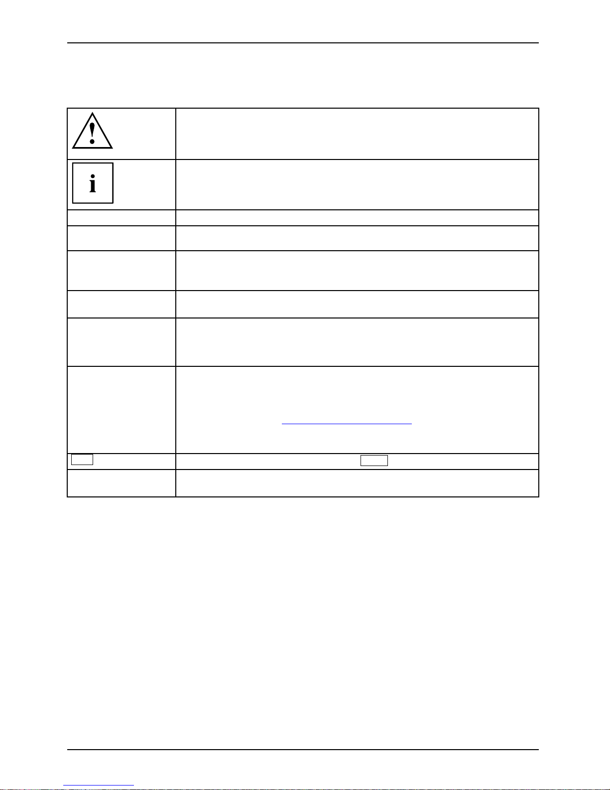
Pay particular attention to text marked with this symbol. Failure to observe
this warning endangers your life, destroys the device, or may lead to loss of
data. Failure to follow the instructions may lead to loss of data, invalidate
your warranty, destroy the device, or endanger your life
indicates important information that is required to use the device properly.
►
refers to an action which you must carry out.
indicates a result
This style
flags data entered using the keyboard in a program dialog or command
line, e.g . your password (Name123) or a command to launch a program
(start.exe)
This style
refers to information displayed by a prog ram on the screen, e.g.:
Installation is completed
This style
is for
• terms and texts in a software user interface, e.g.: ClickSave.
• names of programs or files, e.g. Windows or setup.exe.
"This style"
is for
• cross-references to anot
her section, e.g. "Safety information"
• Cross-references to an external source, e.g. a web address: For more
information, go to"
www.fujitsu-siemens.com"
• indicates names of CDs and
DVDs as well as names a nd titles of other
materials, e.g.: "CD/DVD
Drivers & Utilities" or "Safety" manual
Abc
refers to a key on the keyboard , e.g.:
F10
This style
flags concepts and text that are emphasised or highlighted, e.g.: Do not
switch off device
2 A26391-K226-Z120-1-7619, edition 1
Page 11

Important notes
Important notes
Take note of the safety hints provided in the "Safety" manual, in the "Professional
Notebook" operating manual and in this manual.
A26391-K226-Z120-1-7619, edition 1 3
Page 12
Ports and operating elements
Ports and operating elements
Ports
This chapter presents the individual hardware components of your notebook. You c an obtain
an overview of the ports and operating elements of the notebook. Please familiarise yourself
with these components before you start to work with your notebook.
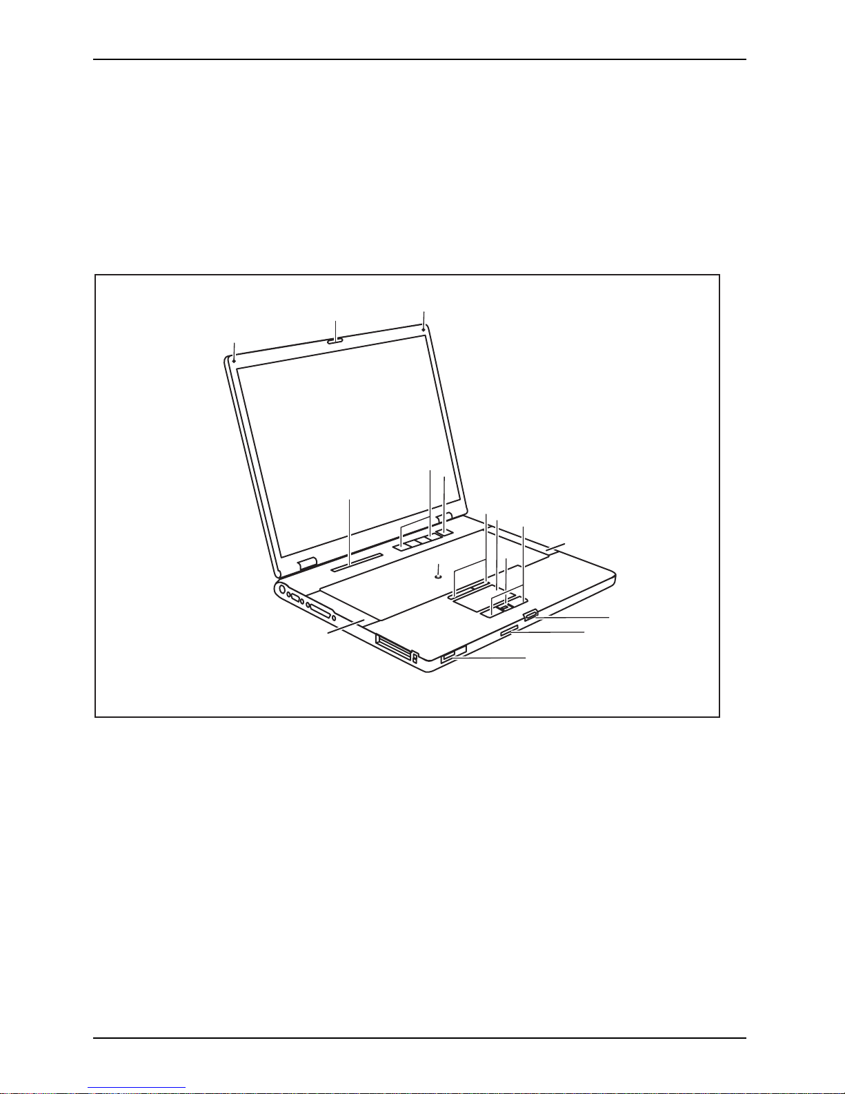
Opened Notebook
FrontViewBuilt-inmicrophone(dependingonmodel)Built-inmicrophone(depending onmodel)LoudspeakerStatusindicatorpanelEasyLaunchkeysOn/OffswitchTouchStic kTouchStickkeysTouch padScrollbarorfingerprintsensorTouchpadkeys
4
3
5
6
7
8
11
2
1
2
9
3
10
12
14
13
1=Camera
2 = Built-in microphones
3 = Loudspeaker
4 = Status indicator panel
5 = Easy Launch keys
6 = On/Off switch
7 = TouchStick
8 = TouchStick keys
9 = Touchpad
10 = Scroll bar o r fingerprint sensor
11 = Touchpad keys
12 = Screen lock
13 = Memory card slot
14 = ON/OFF switch for radio components
4 A26391-K226-Z120-1-7619, edition 1
Page 13

Ports and operating elements
Left side
DCINjackMicrophone portModemportUSBportFireWireportSmartCardreaderPCcardslotExpressCard slotCardejectbuttonHeadphoneport /SPDIF
1234 5 6 78
9
9
10
1=DCINjack
2 = Microphone port
3 = Headphone port / SPDIF (CELSIUS
H250 only)
4 = Modem port
5=USBports
6 = FireWire port
7 = SmartCard reader
8 = PC card slot
9 = Card eject button
10 = ExpressCard slot
Right side
RightsideVie wModuleKensington Lo
ck
12 3
1 = Kensington Lock
2 = Module
3 = Eject lever for module
A26391-K226-Z120-1-7619, edition 1 5
Page 14

Ports and operating elements
Rear
ViewRearKensingtonLockUSBportParallelportSerialportMonitorport(VGA)S-VideoOUTsocketLANport
1
23 4567
1 = Kensington Lock
2 = USB ports
3 = Parallel port
4 = Serial port
5 = Monitor port (VGA)
6 = LAN port
7 = S-Video OUT socket
6 A26391-K226-Z120-1-7619, edition 1
Page 15

Ports and operating elements
Under side
UndersideBatterylockBatteryPortforportreplicatorAirfilterMemorymodule
1
2
3
4
55
1=Airfilter
2 = Port for port replic
ator
3 = Cover for memory modules
4 = Battery
5 = Battery lock
A26391-K226-Z120-1-7619, edition 1 7
Page 16

Ports and operating elements
Switching on the notebook
1
2
► Press the release button (1) and open
the LCD–display panel (2).
1
2
► Press the ON/OFF butt
on (1) to switch
the notebook on.
The power-on indicator of the notebook
appears in the status indicator panel (2).
Windows XP:
You c a n con figure the ON/OFF switch under Start – (Settings) – Control Panel –
Performance and Maintenance – Power Options – Advanced.
Windows Vista:
You c a n c on figure the ON/OFF switch under Start symbol – (Settings) –
Control Panel – Mobile PC – Power Options.
If you have assigned a password, you must en ter this when requested to do so, in
order to start the operating system password. You can find more information in the
"Professional Notebook" operating instructions, "Security functions" section.
8 A26391-K226-Z120-1-7619, edition 1
Page 17

Ports and operating elements
Switching off the Notebook
► Close all programs and shut down your operating system (please see operating system manual).
If the notebook cannot be shut down prope rly, press and hold the ON/OFF button for
approximately four seconds. The notebook will switch off. Any unsaved data may be lost.
► Close the LCD screen so that it
locks into place.
A26391-K226-Z120-1-7619, edition 1 9
Page 18

Ports and operating elements
Status indicator panel
Statusindicatorpanel
The status indicator panel is a small LCD panel on which various symbols appear. These symbols
provide information about the status of the power supply, the drives, and the keyboard functions.
Power-on indicator
CD/DVD indicator
Power indicator Hard disk indicator
Battery charging i
ndicator
PC card/ExpressCard
indicators
First battery ind
icator
Num Lock indicato
r
Second battery indicator Caps Lock indicator
Radio components
indicator
Scroll Lock indicator
10 A26391-K226-Z120-1-7619, edition 1
Page 19

Ports and operating elements
The meanings of the symbols are as follows:
Power-on indicator
Power-onindicatorIndicat or
• Indicator lights up: The notebook is switched on.
• The indicator flashes (1 second on / 1 second off): The notebook is in power
saving mode.
• The indicator does no t light up: The notebook is switched off.
Power indicator
PowerindicatorI ndi cator
Indicator lights up: The mains adapter is supplying pow er to the notebook.
Battery charging indicator
BatterychargingindicatorIndicator
• Indicator lights up: The battery is not being charged/has reached more than
90% of its ma ximum charge, or the battery is being charged.
• The indicator is not lit: The battery is faulty.
Battery indicators
IndicatorIndicatorBattery
The charging state of the batteries is shown by two battery indicators. 1 indicates
that the information applies to the first battery in the battery compart m ent. 2
indicates that the information applies to the second battery in the module bay.
indicates that the battery is 0 % to 25 % charged.
indicates that the battery is 25 % to 50 % charged.
indicates that the battery is 50 % to 75 % charged.
indicates that the battery is 75% to 100% charged
Radio components indicator
IndicatorIndicatorBluetoothIndicatorWirelessLAN
• Indicator lights up: one or more radio components are active.
CD/DVD indicator
IndicatorCD/DVDindi
cator
• Indicator lights up: The CD/DVD in the optical drive is being accessed. You
may only remove the CD/DVD when the indicator is dark.
Hard disk indicator
HarddiskindicatorIndicator
Indicator lights up: The hard disk drive of the notebook is being accessed.
PC card/ExpressCard indicators
IndicatorIndicatorPCCardExpressC
ard
Indicator lights up: A PC card or an ExpressCard is being accessed.
Num Lock indicator
IndicatorNumLock
Indicator lights up: The
Num
key has been pressed. The virtual numeric keypad is
activated. You can output the characters located at the upper right on the keys.
Caps Lock indicator
IndicatorCapsLock
Indicator lights up: The Caps Lock key has been pressed. All the characters you
type appear in upper case. In the case of overlay keys, the character printed on the
upper left of the ke y appears when that ke y is pressed.
Scroll Lock indicator
IndicatorScrollLock
Indi
cator
Roll
Lock
Indicator lights up: The key combination
Fn
+
Scr
has been p ressed. The effect
this key has varies from programme to programme.
A26391-K226-Z120-1-7619, edition 1 11
Page 20

Ports and operating elements
Key combinations
The following description of key combinations refers to functions when using
Microsoft Windows. Some of the following key combinations may not function in
other operating systems and with some device drivers.
Key combinations are entered as follows:
► Press and hold the first key in the combination.
► While holding the first key down, press the other key or keys in the combination.
The key combination
Ctrl
+
Alt Gr
or
Ctrl
+
Alt
canbeusedon
external keyboards that do not not feature a
Fn
key.
Sleep mode
Fn+F1Sleepmod e
This key combination is used to activate the suspend mode (S3).
Enable/disable loudspeakers
Fn+F3LoudspeakersLoudspeakers
This key com bination switches your notebook’s loudspeakers off and on.
An audible signal will be produced when the loudspeakers are switched on.
Switching the touchpad on/off
Fn+F4TouchpadLoudspeakers
This key combination enables and disables the touchpad.
Decrease screen brightness
Fn+F6Screenbright ness
This key combination decreases the brightness of the screen.
Increase screen brightness
Fn+F7Screenbright ness
This key combination increases the brightness of the screen.
Decrease volume
Fn+F8Volum e
This key combination reduces the volume of the integrated loudspeakers.
12 A26391-K226-Z120-1-7619, edition 1
Page 21

Ports and operating elements
Volume increase
Fn+F9Volum e
This key combination raises the volume of the integrated loudspea kers.
Toggle output screen
Fn+F10Toggleout putscreen
If an external monitor is connected, the monitor on which the output is to be
displayed can be selected w ith this key combination.
You can opt to use:
• just the notebook’s LCD screen
• just the external monitor
• both the LCD screen and the external monitor
+
Ctrl
C
Halt current operation (DOS mode)
Ctrl+C
This key combination can be used to halt an operation instantly
without clearing the keyboard buffer.
Switch between open applications
With this key combination you can switch between several open
applications.
Alt+Tab
AltCtrl
Del
SysRq
++
Performwarmboot
This key combination triggers a reset and reboots the notebook. First
press and ho ld both the
Ctrl
and
Alt
key, then press the
Del
key. This will cause the Task Manager to be displayed. The key
combination must be pressed a second time to reboot the system.
Ctrl+Alt+DelWarmboot
Back tab
This key combination moves the cursor back to the previous ta bula r
stop.
Shift+TabBacktab
Key combinations using the Windo
ws keys are detailed in the manual
for your operating system.
A26391-K226-Z120-1-7619, edition 1 13
Page 22

Ports and operating elements
Easy Launch keys
EasyLaunchkeys
Your notebook is equipped with four Easy Launch keys.
RE
Lock Workstation key
This key allows you to lock your workstation. However, you can also configure this key as desired.
Mobility Center key
This button starts the Mobility Center. However, you can also configure this key as desired.
E key
The E key is a simple way of activating and deactivating power management functions (e.g.
reduce screen brightness), see the "Professional Notebook" ma nual.
R key (recovery)
Pressing the R key opens a dialog window in which you can backup or restore data.
Configuring Easy Launch keys
The Application Panel allows you to assign various functions to the E asy Launch keys.
Windows XP:
You will find the Application Panel under Start - (Settings) - Control Panel - Additional
Control Panel Options - Application Panel.
Windows Vista:
You will find the Application Panel und er Start symbol - Programs - Lifebook Application Panel.
14 A26391-K226-Z120-1-7619, edition 1
Page 23

Ports and operating elements
Camera (optional)
Your device is fittedwithaVGAcamera(1),whichcanalsobeusedasawebcam.
1
Further infor
mation on the use of the camera is available with the supplied software.
Ifyoudonotw
ant the camera function, you can disable it in the BIOS.
Removing and installing the battery
NotesBattery
Only use batter
ies approve d by Fujitsu Siemens Computers for your notebook.
Never use force
when inserting or removing a battery.
Make sure that n
o foreign bodies get into the battery connections.
A26391-K226-Z120-1-7619, edition 1 15
Page 24

Ports and operating elements
Removing the battery
► Switch the notebook off and pull the power plug out of the mains socket.
► Close the LCD screen so that it locks into place.
► Disconnect all cables connected to the notebook.
► Turn your notebook over and place it on a stable, flat and clean surface. If necessary, lay
an anti-slip cloth on this surface to prevent the n otebook from being scratched.
1
1
2
► Press the two unlocking lugs (1), hold them down and lift the battery slightly.
► Remove the battery from the battery compartment (2).
Installing battery
► Position the battery at th e edge.
► Push the batter
y into the battery compartment until you feel it engage.
16 A26391-K226-Z120-1-7619, edition 1
Page 25

Ports and operating elements
Removing and installing the air filter
Cleantheexistingairfilter regularly. Dirty air filters will lead to an increased
temperature inside the device. Operat ing temperatures which are too high
can lead to loss of data and unreliable operation.
Air filter removal
► Switch off your notebook and disconnect the power plug from the mains.
► Close the LCD screen so that i
t locks into place.
► Disconnect all cables connected to the notebook.
► Turn your notebook over and pla
ce it on a stable, flat and clean surface. If necessary, lay
a non-slip cloth on this sur fa
ce to prevent the notebook from being scratched.
1
1
2
► Keep the locking t
abs of the air filter pressed down (1).
► Remove the air fi lter from its location (2).
► Clean the air filter
with a dry brush.
A26391-K226-Z120-1-7619, edition 1 17
Page 26

Ports and operating elements
Install air filter
Make sure that the arrow (a) on the air filter points in the correct direction and that you
insert the air filter again in the same orientation as it w as before the cleaning operation.
1
a
► Insert the air filter into its location so that it is felt to engage (1).
► Turn th e notebook t
he right way up and place it on a flat surf ace.
► Reconnect the cables that you disconnected previously.
18 A26391-K226-Z120-1-7619, edition 1
Page 27

Ports and operating elements
SIM card
Follow the inst ructions supplied by the provider of the SIM card.
Inserting the SIM card
► Switch the notebook off and pull the power plug out of the mains socket.
► Close the LCD screen so that i
t locks into place.
► Disconnect all cables connected to the notebook.
► Turn your notebook over and pla
ce it on a stable, flat and clean surface. If necessary, lay
an anti-slip cloth on this sur
face to prevent the notebook from being scratched.
► Remove the battery (see Section "
Removing the batter y", Page 16).
1
2
a
► SlidetheSIMcardintothesl
ot (1) (with the
contacts facing upwards) u
ntil it engages.
► Slide the clip (a) of the SIM card in the
direction of the arrow (2).
► Reinstall the battery (see "
Installing battery", Page 16).
► Turn the notebook the right way up and place it on a flat surface.
► Reconnect the cables that you disconnected previously.
A26391-K226-Z120-1-7619, edition 1 19
Page 28

Ports and operating elements
Removing a SIM card
► Switch the notebook off and pull the power plug out of the mains socket.
► Close the LCD screen so that it locks into place.
► Disconnect all cables connected to the notebook.
► Turn your notebook over and place it on a stable, flat and clean surface. If necessary, lay
an anti-slip cloth on this surface to prevent the n otebook from being scratched.
► Remove the battery (see Section "
Removing the batter y", Page 16).
a
1
2
► Slide the clip (a) of the SIM card in the
direction of the arrow (1).
► Press on the edge of the SIM card so that
it jumps up slightly out of the slot.
► Pull the SIM card out of the slot in the
direction of the arrow (2).
► Reinstall the battery (see "
Installing battery", Page 16).
► Turn th e notebook the right way up and place it on a flat surface.
► Reconnect the cables that you disconnected previously.
20 A26391-K226-Z120-1-7619, edition 1
Page 29

Ports and operating elements
Radio components: UMTS (optional)/wireless
LAN/Bluetooth
WirelessLANBluetoothUMTS
The installation of a w ireless LAN, Bluetooth or UMTS module not approved by Fujitsu
Siemens Computers GmbH voids the permits (CE!, FCC) issued for this device.
The modules for radio components are switched off during shipping.
Switching the radio components on and off
► Slide the ON/OFF switch into the "ON"
position to activate the radio components.
WirelessLANWirelessLA NBluetoothBluetooth
or
► Slide the ON/OFF switch to th e
"OFF" position to deactivate the
radio components.
If you switch off the radio components, the Bluetooth and UMTS modules are powered
off and the wireless LAN transmission unit (antenna) is switched off.
You c an also deactivate the radio components individually in the BIOS setup.
You must have assigned the supervisor password in order for this function to be available.
Pay attention to the additional safety notes for devices with rad io
components provided in the "Safety" manual.
Details on using the wireless LAN are contained in the online help for your
wireless LAN software and in the "Wireless LAN" manual. (The "Wireless LAN"
manual can be found on the "Drivers & Utilities" CD/DVD .)
You ca n fi nd more information on how to use Bluetooth on the CD you
received with your Bluetooth software.
You can obtain more information on UMT S from your service provider.
A26391-K226-Z120-1-7619, edition 1 21
Page 30

Removing and installing components
during servicing
Removing and installing compo
nents
during servicing
Only qualified technicians should repair your notebook. U n authorised
opening o r incorrect repair may greatly endanger the user (electric shock,
fire risk) and will invalidate y our warranty.
Components
Servicing
You may remove and install the components described in this chapter yourself
after consulting the Hotline/Help Desk.
If you remove and install components without consulting the Hotline/Help
Desk, then the warranty of your notebook will be voided.
Notes on installing and removing boards
and components
• Switch the notebook off and pull the power plug out of the mains socket.
• Remove the battery.
• Take care when you use the locking mechanisms on the battery and any other component.
• Never use sharp objects suc
h as screwdrivers, scissors or knives as leverage to remove covers.
NotesBoardESD
Boards with electrostatic sensitive devices (ESD) are marked with the label
shown.
When handling b oards fitted with ESDs, you must always observe the following
points:
• You must always discharge static build up (e.g. by touching a grounded
object) before working.
• The equipment and tools you use must be free of static charges.
• Remove the power plug from the mains supply befo re inserting or removing
boards containing ESDs.
• Always hold boards with ESDs by their edges.
• Never touch pins or conductors on boards fitted with ESDs.
22 A26391-K226-Z120-1-7619, edition 1
Page 31

Removing and installing components
during servicing
Removing and installing memory
modules
MainmemoryMemoryexpansionMemoryupgradeSystemexpansion
The notebo ok will not start without memory modules, as no fixed m ain memory is installed.
Your notebook supports dual-channel DDR2 technology.
The dual-channel DDR2 technology can only be used with two identical memory
modules. When two different memory modules are installed, only "single-channel"
mode is supported. This reduces the performance of your notebook.
If you are asked by the Hotline/Help Desk to remove and install the memory
modules yourself, proceed as follows:
Pay attention to the relevant safety notes provided in the "Important notes" chapter.
The notebook must be switched off when installing/removing the memory
modules, it must not be in Suspend mode.
Only use approved memory expansion modules in your notebook
(see Section "
Technical data", Page 26).
Never use f orce when installing or removing memory modules.
Make sure that foreign objects do not fall into the memory expansion compartment.
Individual components (e.g. the p
rocessor hea t sink) can become very hot
during operation. Therefore, w
e recommend that you wait one hour after
switching off the notebook bef
ore removing or installing the memory modules.
Otherwise, there is a risk of su
ffering burns!
As some non-ESD safe component
s are exposed, please observe the section "
Notes
on installing and removing boa
rds and components", Page 22.
► Switch yo ur no tebook off and unplug the mains adapter from the ma ins o utlet.
► Close the LCD screen so that it locks into place.
► Disconnect all cables connected to the notebook.
► Turn your notebook over and place it on a stable, flat and clean surface. If necessary, lay
an anti-slip cloth on this surface to prevent the notebook from being scratched.
► Remove the battery (see "
Removing the battery", Page 16).
A26391-K226-Z120-1-7619, edition 1 23
Page 32

Removing and installing components
during servicing
Cover removal
1
2
► Remove the screw (1).
► Pull the co ver off the notebook (2).
Removing memory modules
3
2
1
1
► Carefully push the two m ounting
clips outwards (1).
MemoryexpansionMemorymodule
The memory module snaps upwa rds (2).
► Pull the memory module out of its slot
in the direction of the arrow (3).
Installing a
memory module
2
a
1
► Insert the memory modu le with the contacts
and the recess (a) facing the slot (1).
Memory
expansion
Memory
module
► Carefully pu
sh the memory module
downwards un
til you feel it click
into place (2
).
24 A26391-K226-Z120-1-7619, edition 1
Page 33

Removing and installing components
during servicing
Attaching the cover
2
1
► Place the cover in the correct
mounting position (1).
► Fasten the cover w ith the s crew (2).
► Reinstall the battery (see "
Installing battery", Page 16).
► Turn the notebook the right way up and place it on a flat surface.
► Reconnect the cables that you disconnected previously.
A26391-K226-Z120-1-7619, edition 1 25
Page 34

Technical data
Technical data
CELSIUS H250/LIFEBOOK E8410
Technicaldata
Device Celsius H250
LIFEBOOK E8410
(external graphics)
LIFEBOOK E8410
(internal graphics)
Processor
Intel Core2™ Duo (Merom)
Main memory
Maximum 4 Gbyte DDR2 SDRAM
2 slots f or 256, 512 Mbyte modules, 1 Gbyte or 2 Gbyte modules
Possible modules
• Second battery
• Second hard disk drive
• Combo drive (CD-RW/DVD)
• Super-multi format DVD drive w ith double layer support
• Blank slot (weight saver)
Electrical data
Regulations complied
with
CE, CE!, Energy Star, EN55022, EN55024, EN301489, EN300328,
EN301893, EN50371, UL NoA / CB
Protection class II
Maximum power draw
(notebook on with battery
charging)
100 W 100 W 80 W
LCD screen
Screen size (diagonal)
15.4 inches TFT
WUXGA (1920 x
1200) / 15.4 inches
TFT WSXGA+ (1680
x 1050), 16 million
colours
15.4 inches TFT
WXGA (1280 x 800)
/ 15.4 inches TFT
WSXGA+ (1680 x
1050), 16 million
colours
15.4 inches TFT
WXGA (1280 x 800)
/ 15.4 inches TFT
WSXGA+ (1680 x
1050), 16 million
colours
Graphics card
Chip NVIDIA Q uadro FX
570M
NVIDIA GeForce 8400 Intel GM965
Video memory (VRAM) GDDR3 256 Mbyte GDDR3 128 Mbyte
shared memory
Audio
Soundchip ALC 262
Dimensions
Width x Depth x Height
(front/back)
357 mm x 257 mm x 35.5/36.5 mm
Weight with blank slot
(Weight Saver)
approx. 2.7 kg
Input devices
Keyboard 86 keys
Touchpad 1 touchpad, 2 touchpad keys
TouchStick
1 touchstick, 2 touchstick keys
26 A26391-K226-Z120-1-7619, edition 1
Page 35

Technical data
Slots
ExpressCard slot 1 x ExpressC a rd/3 4 or ExpressCar
d/54
PC card slot PCMCIA 1 x type I or II
Memory card slot
1 x Secure Digital, 1 x MemoryStick or 1 x MemoryStickPro
SIM card s lot
1x
Ports
S-Video out socket 7-pin mini DI N female connector
Monitor port (VGA)
15-pin socket
Modem port
Connector, RJ11
LAN port
Socket, RJ45
Parallel port 25-pin socket
Serial port
9-pin plug
Microphone port / Line In
3.5 mm mono mini-jack
Headphones port/Line
Out
3.5 mm stereo mini-jack (combined with optica l SPDIF output on
CELSIUS H250)
FireWire port
S400, 4-pin
USB port 4 x USB 2.0
Infrared interface
IrDA 1.1
Docking port 100-pin
Environmental conditions
Environment class (3K2) DIN IEC 721
Mechanical class (7M2) DIN IEC 721
Temperature
Operation 5 °C ... 35 °C
Transport
-15 °C ... 60 °C
Battery
Techn ica
ldata
Rated voltage 14.4 V
Rated capacity 74.9 Wh
The operating time depe nds on the device co nfigu ration, the active
applications and the energy saving settings.
A26391-K226-Z120-1-7619, edition 1 27
Page 36

Technical data
Mains adapter 80W
Technicaldata
Use ONLY the 80W mains adapter for a LIFEBOOK E8410 (internal graphics) !
Rated v oltage
100 V to 240 V (automatic)
Max. rated current 4.22 A
An additional mains adapter or power cable can be ordered at an y time.
100W mains adapter
Technicaldata
Use ONLY the 100W mains adapter for a LIFEBOOK E8410 with external
graphics or for the CELSIUS H250 workstation !
If you dock the LIFEBOOK E8410 with external graphics or the CELSIUS H250 mobile
workstation, you must connect a 100W m ains adapter to the port replicator. You will
find the exact data on the rating plate of the mains adapt er (19 V / 5.27 A).
Rated v oltage
100 V to 240 V (automatic)
Max. rated current 5.27 A
An additional mains adapter or power cable can be ordered at an y time.
28 A26391-K226-Z120-1-7619, edition 1
Page 37

Index
Index
A
Air filter 7
Alt+Tab 13
B
Back tab 13
Battery 7
important notes 15
indicator 11
Battery charging indicator 11
Battery lock 7
Bluetooth 21
Indicator 11
Switching off 21
Switching on 21
Board 22
Built-in microphone (depending on model) 4
C
Caps Lock
indicator 11
Card eject button 5
CD/DVD indicator 11
Components
installing / removing 22
Ctrl+Alt+Del 13
Ctrl+C 13
D
DC IN jack 5
E
Easy Launch keys 4, 14
ESD 22
ExpressCard
indicator 11
ExpressCard slot 5
F
FireWire port 5
Fn + F1 12
Fn + F10 13
Fn + F3 12
Fn + F4 12
Fn + F6 12
Fn + F7 12
Fn + F8 12
Fn + F9 13
Front 4
H
Hard disk indicator 11
Headphone port / SPDIF 5
I
Indicator
Battery charging indicator 11
Bluetooth 11
Caps Lock 11
CD/DVD 11
ExpressCard 11
First battery 11
Hard disk indicator 11
Num Lock 11
PC-Card 11
Power indicator 11
Power-on indicator 11
Radio components 11
Roll Lock 11
Scroll Lock 11
Second battery 11
Wireless LAN 11
K
Kensington Lock 5–6
L
LAN port 6
Loudspeaker 4
Loudspeakers
disable 12
enable 12
M
Main memory 23
Memory expansion 23
installing 24
removing 24
Memory module 7
installing 24
removing 24
Memory upgrade 23
Microphone p ort 5
Modem port 5
Module 5
Monitor port (VGA) 6
A26391-K226-Z120-1-7619, edition 1 29
Page 38

Index
N
Notes
battery 15
boards 22
Num Lock
indicator 11
O
On/Off switch 4
P
Parallel port 6
PC Card
indicator 11
PC card slot 5
Port for port replicator 7
Ports 4
Power indicator 11
Power-on indicato r 11
R
Rear 6
Right side 5
Roll Lock
indicator 11
S
S-Video OUT socket 6
Screen brightne ss
decrease 12
increase 12
Scroll bar or fingerprint sensor 4
Scroll Lock
indicator 11
Serial port 6
Servicing 22
Shift+Tab 13
Sleep mode
activating 12
SmartCard reader 5
Status indicator panel 4, 10
System expansion
memory expansion 23
T
Technical data
battery 27
Mains adapter 28
notebook 2 6
Toggle output screen 13
Touchpad 4
disable 12
Touchpad keys 4
To u ch St ic k 4
TouchStick keys 4
U
UMTS 21
Under side 7
USB port 5–6
V
View
front 4
rear 6
Right side 5
Volume
decrease 12
increase 13
W
Warm boot 13
Wireless LAN 21
Indicator 11
Switching off 21
Switching on 21
30 A26391-K226-Z120-1-7619, edition 1
 Loading...