

Fujitsu Siemens Computers AU* G45LRLA, AR* G45LMLA, AO* G45LETL, AR* G54LHTA, AO* G54LETL Service Instruction
...Page 1
SPLIT TYPE
ROOM AIR CONDITIONER
Cassette type
Duct type
Ceiling type
Models Indoor unit Outdoor unit
AU* G45LRLA
AR* G45LMLA
AR* G45LHTA
AB* G45LRTA
AU* G54LRLA
AR* G54LHTA
AO* G45LETL
AO* G54LETL
INVERTER
SERVICE
INSTRUCTION
R410A
Page 2

CONTENTS
1. SPECIFICATIONS
1. DESCRIPTION OF EACH CONTROL OPERATION
1-1 COOLING OPERATION..............................................................................................
1-4 AUTO CHANGEOVER OPERATION.........................................................................
1-5 INDOOR FAN CONTROL...........................................................................................
1-6 OUTDOOR FAN CONTROL.......................................................................................
1-7 COMPRESSOR CONTROL.......................................................................................
01-01
1-2 HEATING OPERATION..............................................................................................
01-02
1-3 DRY OPERATION.......................................................................................................
01-03
01-04
01-06
01-09
01-10
1-8 TIMER OPERATION CONTROL................................................................................
01-11
1-9 ELECTRONIC EXPANSION VALVE CONTROL.......................................................
01-15
1-10 TEST OPERATION CONTROL...............................................................................
01-15
1-11 PREVENT TO START FOR 3 MINUTES (3 MINUTES ST).....................................
01-16
1-12 4-WAY VALVE EXTENSION SELECT.....................................................................
01-16
1-13 AUTO RESTART......................................................................................................
01-16
1-14 PUMP DOWN...........................................................................................................
01-17
1-15 COMPRESSOR PREHEATING...............................................................................
01-18
1-16 10°C HEAT OPERATION (For AB type)..................................................................
01-18
1-20 VARIOUS PROTECTIONS.......................................................................................
01-22
1-21 COMPRESSOR STOP CONTROL...........................................................................
01-24
1-19 OFF DEFROST OPERATION CONTROL................................................................
01-21
2-1 ERROR DISPLAY......................................................................................................
2. TROUBLE SHOOTING
2-2 TROUBLE SHOOTING WITH ERROR CODE..........................................................
2-3 TROUBLE SHOOTING WITH NO ERROR CODE....................................................
2-4 SERVICE PARTS INFORMATION............................................................................
02-01
02-30
02-04
02-35
1-18 DEFROST OPERATION CONTROL........................................................................
01-19
1-17 ECONOMY OPERATION.........................................................................................
01-18
1-27 DESCRIPTION OF DISPLAY UNIT..........................................................................
01-27
1-24 LOW NOISE OPERATION.......................................................................................
01-25
1-25 PEAK CUT OPERATION..........................................................................................
01-25
1-26 DRAIN PUMP OPERATION (For AU/ AR type)......................................................
01-26
1-23 EXTERNAL ELECTRICAL HEATER CONTROL.....................................................
01-25
1-22 FRESH AIR CONTROL............................................................................................
01-24
Page 3

1 . DESCRIPTION OF EACH
CONTROL OPERATION
R410A
Cassette/ Duct/ Ceiling type
INVERTER
Page 4

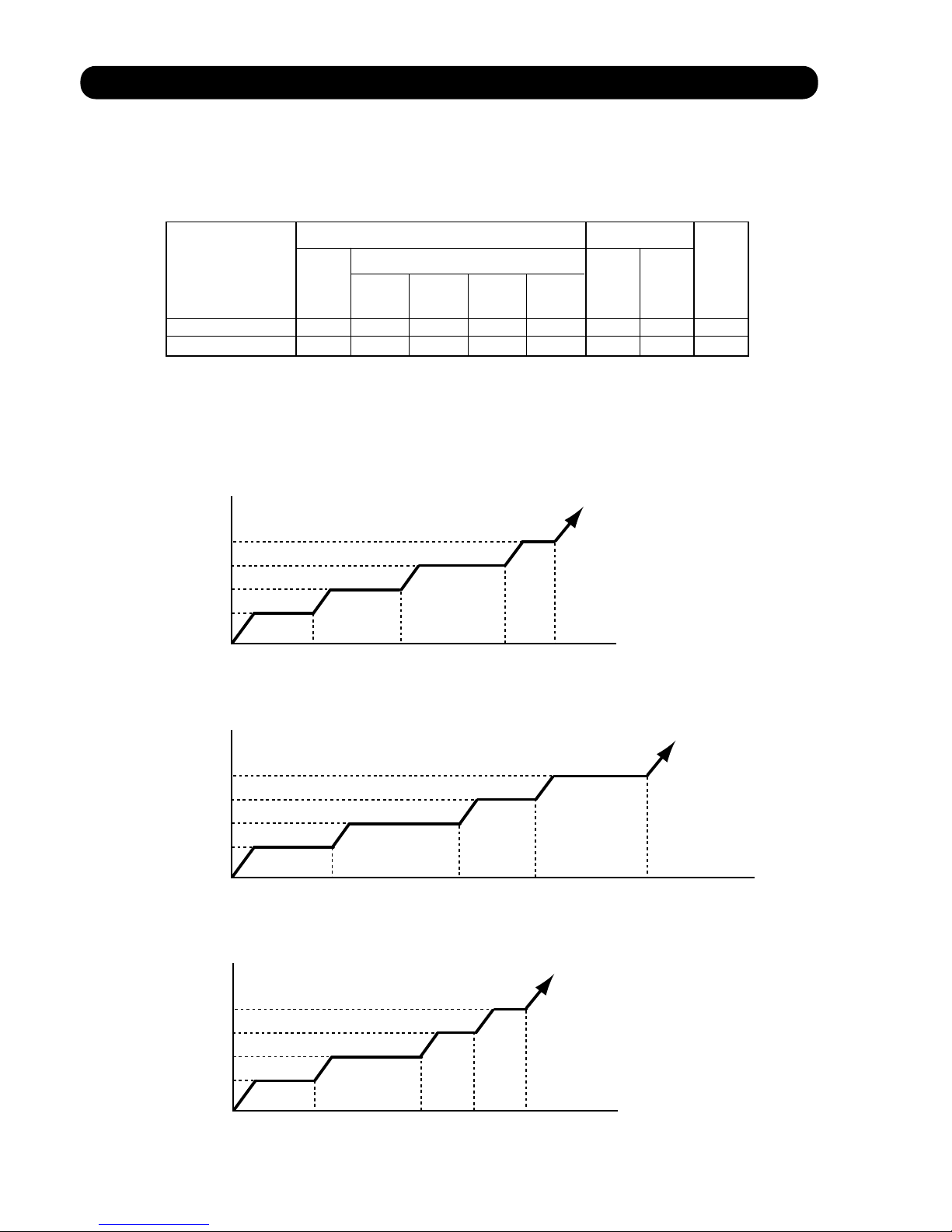
1-1. COOLING OPERATION
A sensor (room temperature thermistor) built in the indoor unit will usually perceive
difference or variation between a set temperature and present room temperature, and
controls the operation frequency of the compressor.
* If the room temperature is 2°C higher than a set temperature,
the compressor operation frequency will attain to maximum performance.
* If the room temperature is 2.5°C lower than a set temperature, the compressor
will be stopped.
* When the room temperature is between +2°C to -2.5°C of the setting temperature,
the compressor frequency is controlled within the range shown in Table1.
However, the maximum frequency is limited in the range shown in Figure 1 based on the
fan speed mode and the outdoor temperature.
minimum
frequency
maximum
frequency
16rps
16rps
16rps
16rps
93rps
90rps
85rps
100rps
AU* G45LRLA
AR* G45LMLA
AB* G45LRTA
AR* G45LHTA
AU* G54LRLA
AR* G54LHTA
Hi Me Lo Qu
93rps
93rps
78rps
73rps
75rps
75rps
68rps
56rps
68rps
68rps
56rps
47rps
44rps
44rps
44rps
29rps
100rps
100rps
85rps
76rps
78rps
78rps
73rps
62rps
73rps
73rps
62rps
50rps
44rps
44rps
44rps
29rps
85rps
85rps
78rps
68rps
77rps
77rps
68rps
62rps
76rps
76rps
68rps
56rps
---
---
---
---
90rps
90rps
85rps
73rps
85rps
85rps
76rps
68rps
81rps
81rps
73rps
62rps
---
---
---
---
A zone
B zone
C zone
AU* G45LRLA
AR* G45LMLA
AB* G45LRTA
AU* G54LRLA
D-F zone
A zone
B zone
C zone
D-F zone
A zone
B zone
C zone
AR* G45LHTA
AR* G54LHTA
D-F zone
( Table 1 : Compressor Frequency Range )
( Fig. 1 : Limit of Maximum Frequency based on Outdoor Temperature )
01-01
A zone
B zone
C zone
D-F zone
Fan speed mode
1. DESCRIPTION OF EACH CONTROL OPERATION
Outdoor air
temperature
A zone
B zone
C zone
D zone
E zone
F zone
When the room
temperature rises
When the room
temperature drops
36°C
32°C
21°C
12°C
2°C
34°C
30°C
19°C
10°C
0°C
Page 5
1-2. HEATING OPERATION
A sensor (room temperature thermistor) built in the indoor unit will usually perceive
difference or variation between a set temperature and present room temperature, and
controls the operation frequency of the compressor.
* If the room temperature is lower 3°C than a set temperature,
the compressor operation frequency will attain to maximum performance.
* If the room temperature is higher 2.5°C than a set temperature, the compressor
will be stopped.
* When the room temperature is between +2.5°C to -3°C of the setting temperature,
the compressor frequency is controlled within the range shown in Table2.
( Table 2 : Compressor Frequency Range )
01-02
minimum
frequency
maximum
frequency
16rps
110rps
AU* G45LRLA
AR* G45LMLA
AB* G45LRTA
AR* G45LHTA
AU* G54LRLA
AR* G54LHTA
Page 6
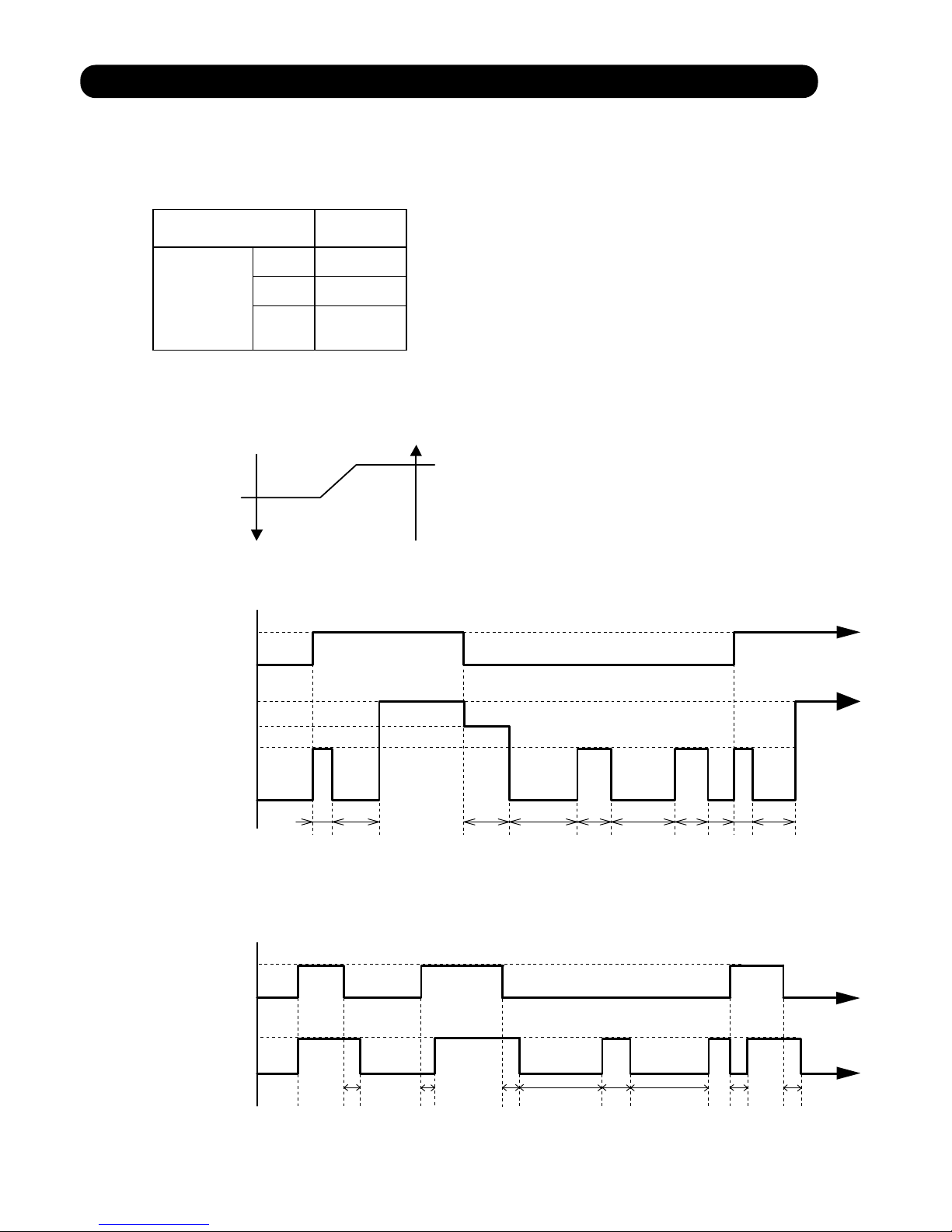
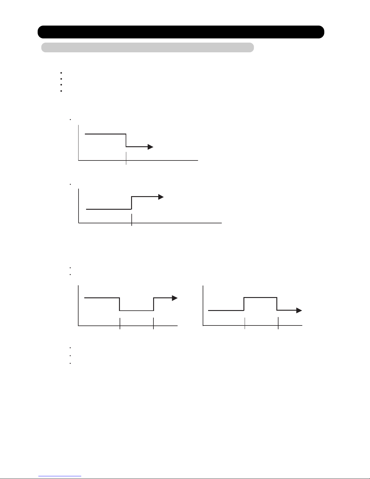
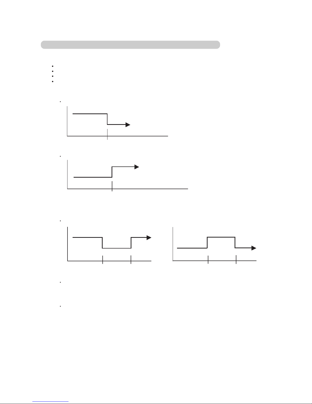
1-3. DRY OPERATION
The compressor rotation frequency shall change according to set temperature and room
temperature variation which the room temperature sensor of the indoor unit has detected
as shown in the Table 3.
( Table 3 : Compressor frequency )
( Fig.2 : Compressor Control based on Room Temperature )
01-03
Ts : Setting temperature
Ts+0.5°C
Ts+1.5°C
Operating
frequency
44rps
X zone
0rps
Y zone
Room Room
temperature temperature
X zone
Y zone
AU* G45LRLA
AR* G45LMLA
AB* G45LRTA
AR* G45LHTA
AU* G54LRLA
AR* G54LHTA
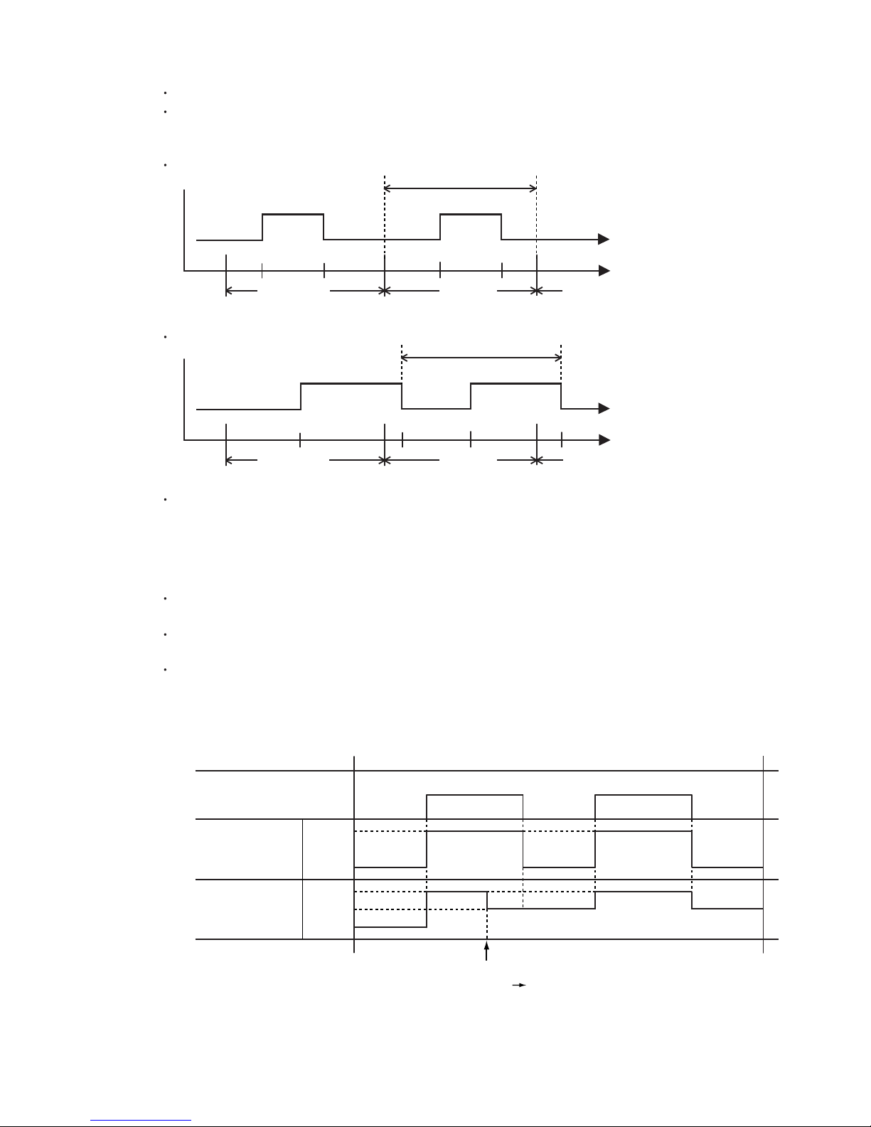
Compressor
ON
OFF
Indoor fan
Setting air flow
OFF
10 30 60 180 60 180 60 10 30
(sec)
S-Lo
Compressor
ON
OFF
Lo
OFF
30 180 120 180 30
(sec)
Indoor fan
ON
5 30 5
( Fig 3-2 : Indoor Fan Control for AR*G45/ 54LHTA )
( Fig 3-1 : Indoor Fan Control for AU*G45/ 54LRTA, AR*G45LMLA, AB*G45LRTA )
Indoor fan air flow *1
*1 : AU*G45LRLA ---> 470rpm, AU*G54LRLA ---> 480rpm
AB*G45LRTA ---> 680rpm, AR*G45LMLA ---> 670rpm,
Page 7
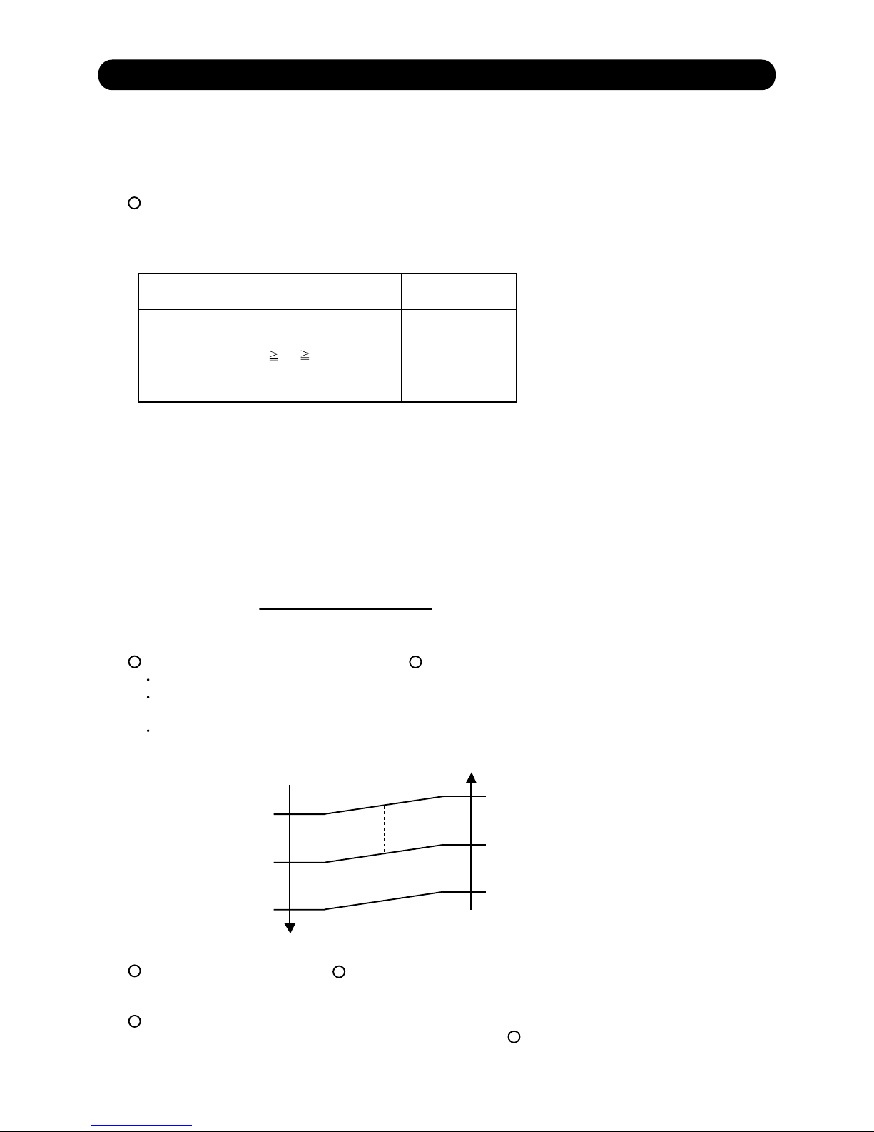
1-4. AUTO CHANGEOVER OPERATION
01-04
When the air conditioner is set to the Auto mode by remote controller, operation starts in the optimum
mode from among the Heating, Cooling, Dry and Monitoring mode. During operation, the
optimum mode is automatically switched in accordance with temperature changes. The temperature
can be set between 18°C and 30°C in 1°C steps.
When operation starts, indoor fan and outdoor fan are operated for around 3 minutes.
Room temperature and outdoor temperature are sensed, and the operation mode is selected
in accordance with the table below. <Monitoring mode>
Cooling mode
25°C
Heating mode
( Table 4 : Operation mode selection table )
Room temperature (TR)
TR> Ts+2°C
Ts+2°C TR Ts -2°C
*Middle zone
TR < Ts -2°C Heating
When Cooling or Dry mode was selected at and air flow mode is Auto, the air conditioner operates as follow.
The same operation as COOLING OPERATION AND DRY OPERATION of page 01-01 is performed.
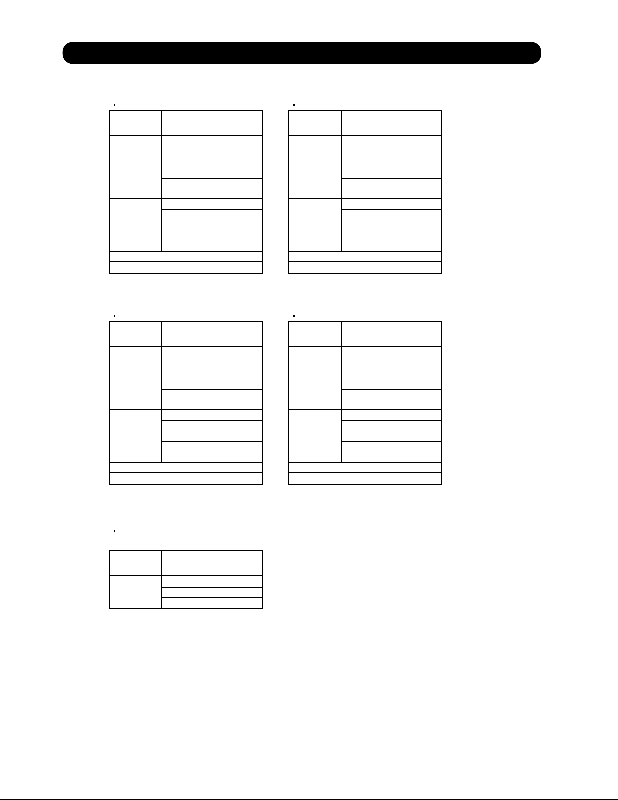
When the room temperature has remained at set temperature -1.5°C, operation is automatically
switched to Dry mode.
If the room temperature reaches set temperature +2°C during Dry mode, operation returns to Cooling.
When Heating was selected at , the same operation as HEATING OPERATION of page
01-02 is performed.
When the compressor was stopped for 6 consecutive minutes by the temperature control function
after the Cooling(Auto:Dry) or Heating mode was selected at above, operation is switched
to Monitoring and the operation mode is selected again.
1
1
2
3
1
4
1
( Fig.4 : Outdoor temperature zone selection )
Cooling
(Autmatic dry)
Operation mode
*If it's Middle zone, operation mode of indoor unit is selected as below.
(1). Same operation mode is selected as outdoor unit.
If outdoor unit is operating in Cooling, Dry, and Heating mode,
indoor unit will be operated by the same operation mode.
(2). Selected by the outdoor temperature.
If outdoor unit is operating in other than Cooling, Dry, and Heating mode, indoor unit will be operated
according to the outdoor temperature as below.
Cooling
Cooling
Dry
Dry
Compressor stop
When the room
temperature drops
When the room
temperature rises
Ts +2°C
Ts -0.5°C
Ts -1.5°C
Ts +1°C
Ts -1.5°C
Ts -2.5°C
( Fig.5 : Auto changeover : Cooling - Dry )
TR : Room temperature
Ts : Setting temperature
TR : Room temperature
Ts : Setting temperature
( Air flow mode : Auto )
Page 8
01-05
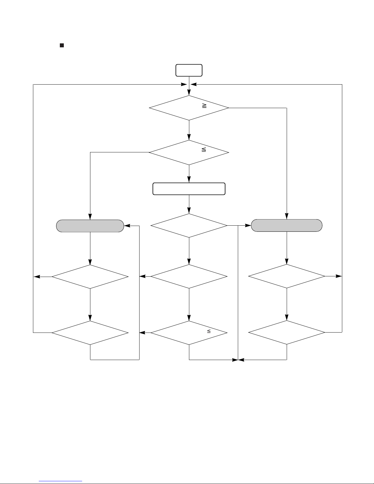
START
Room temp.
Ts+2°C?
COOLING (AUTO:DRY)
OPERATION
HEATING OPERATION
YES
YES
NO
NO
NO
AUTO CHANGEOVER operation flow chart
TS : Setting temperature
Room temp.
Ts -2°C?
Thermostat remains
in OFF state for 6 minutes or
longer?
System stops
or operation command other than
auto changeover operation?
NO
Thermostat remains
in OFF state for 6 minutes or
longer?
System stops
or operation command other than
auto changeover operation?
Middle zone
NO
Operation mode of
outdoor unit : Cooling or Dry?
YES
NO
Operation mode of outdoor unit
: Heating?
YES
NO
YES
Outdoor temperature
25°C?
NO
YES
YES
NO
YES
YES
Page 9
1-5. INDOOR FAN CONTROL
1. Fan speed
( Table 5 : Indoor Fan Speed )
2. FAN OPERATION
The airflow can be switched in 5 steps such as Auto, Quiet, Lo, Me, Hi, while the indoor fan only runs.
The High Static Pressure Duct type is 4 steps such as Auto, Lo, Me, Hi.
01-06
AU* G45LRLA
Operation
mode
Air flow
mode
Speed
(rpm)
Hi
Me+
Me
Lo
Quiet
Cool air prevention
Hi
Me
Lo
Quiet
*Soft Quiet
690
650
610
550
470
300
690
610
550
470
300
470
270
Heating
Cooling
Fan
Dry
S-Lo
AU* G54LRLA
Operation
mode
Air flow
mode
Speed
(rpm)
Hi
Me+
Me
Lo
Quiet
Cool air prevention
Hi
Me
Lo
Quiet
*Soft Quiet
720
680
630
570
480
300
720
630
570
480
300
480
270
Heating
Cooling
Fan
Dry
S-Lo
*Note, during Economy operation and operation mode is Fan, air flow is 1 step downs.
(Hi > Me, Me > Lo, Lo > Quiet, Quiet > Soft Quiet)
AB* G45LRTA
Operation
mode
Air flow
mode
Speed
(rpm)
Hi
Me+
Me
Lo
Quiet
Cool air prevention
Hi
Me
Lo
Quiet
*Soft Quiet
1200
1100
1000
830
680
500
1200
1000
830
680
500
680
250
Heating
Cooling
Fan
Dry
S-Lo
AR* G45LMLA
Operation
mode
Air flow
mode
Speed
(rpm)
Hi
Me+
Me
Lo
Quiet
Cool air prevention
Hi
Me
Lo
Quiet
*Soft Quiet
1300
--1020
840
670
--1310
1020
840
670
420
670
420
Heating
Cooling
Fan
Dry
S-Lo
*Note, during Economy operation and operation mode is Fan, air flow is 1 step downs.
(Hi > Me, Me > Lo, Lo > Quiet, Quiet > Soft Quiet)
AR* G45/ 54LHTA
(Normal static pressure: 100Pa)
Operation
mode
Air flow
mode
Speed
(rpm)
Hi
Me
Lo
1300
1150
1000
Heating
Cooling
Fan
Page 10
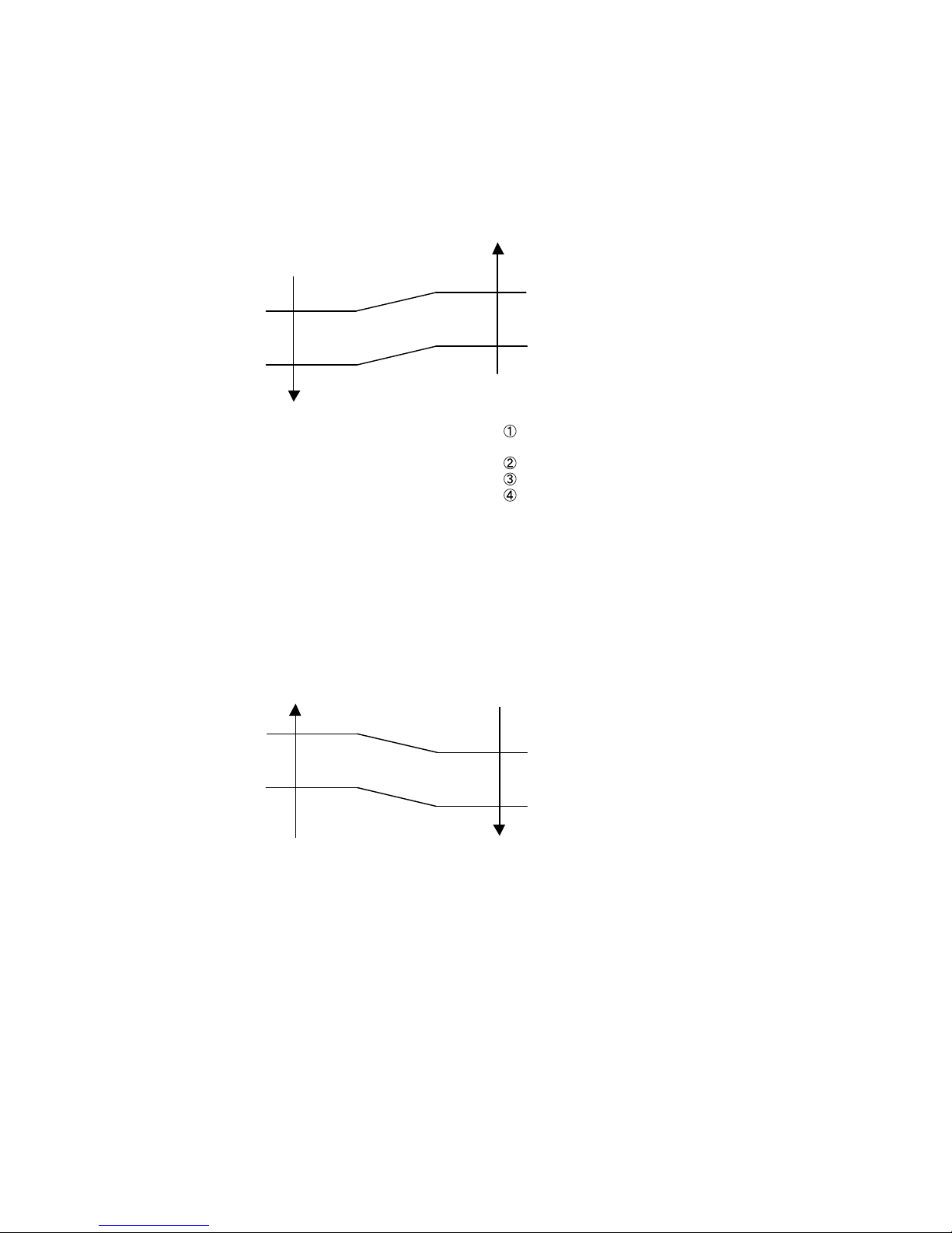
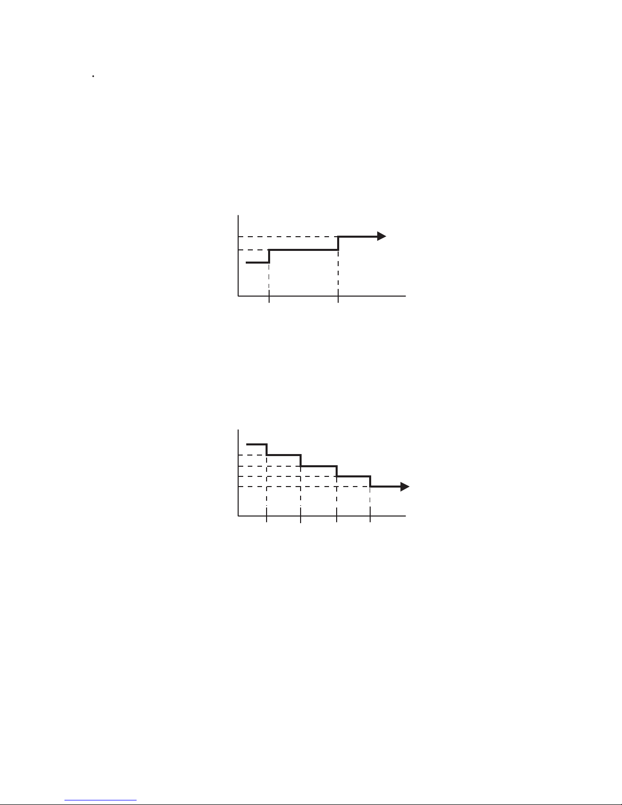
4. HEATING OPERATION
Switch the airflow [Auto], and the indoor fan motor will run according to a room temperature,
as shown in Fig.7.
On the other hand, if switched in [Hi] ~ [Lo], the indoor motor will run at a constant airflow
of [Heat] operation modes Lo, Me, Hi, as shown in Table 5.
01-07
( Fig.7 : Airflow change - over ( Heating : Auto ) )
3. COOLING OPERATION
Switch the airflow [Auto], and the indoor fan motor will run according to a room temperature,
as shown in Fig.6.
On the other hand, if switched in [Hi] ~ [Lo], the indoor motor will run at a constant airflow of [Cool]
operation modes Lo, Me, Hi, as shown in Table 5.
( Fig.6 : Airflow change - over ( Cooling : Auto ) )
When the room
temperature rises
When the room
temperature drops
TR : Room temperature
Ts : Setting temperature
TR-Ts > 2°C
=
1°C > TR-Ts
2°C > TR-Ts > 1°C
=
TR-Ts > 2.5°C
=
1.5°C > TR-Ts
2.5°C > TR-Ts > 1.5°C
=
Hi mode
Me mode
Lo mode
*1
When the room
temperature rises
When the room
temperature drops
TR-Ts > -1°C
=
-2°C > TR-Ts
-1°C > TR-Ts > -2°C
=
TR-Ts > -1.5°C
=
-2.5°C > TR-Ts
-1.5°C > TR-Ts > -2.5°C
=
Lo mode
Me mode
Hi mode
*1 : Contains a condition to the following
When the operation mode is set to AUTO mode
at the start of operation.
When the setting temperature was changed.
When the operation mode was changed to Cooling mode.
When the airflow mode was changed to AUTO mode.
Page 11
5. COOL AIR PREVENTION CONTROL (Heating mode)
6. DRY OPERATION
Refer to the Fig. 3-1, 3-2.
During the dry mode operation, the fan speed setting can not be changed.
7. [For AU*G45/ 54LRTA, AR*G45LMLA, AB*G45LRTA]
MOISTURE RETURN PREVENTION CONTROL (Cooling mode& Dry mode)
Switch the airflow [Auto] at cooling mode, and the indoor fan motor will run as shown in Fig.3-1.
8. [For AU*G45/ 54LRTA, AR*G45LMLA, AB*G45LRTA]
INDOOR UNIT FAN (CONTROL FOR ENERGY SAVING (Cooling mode))
Switch the airflow at cooling mode, and the indoor fan motor will run as shown in Fig.3-1.
It depends on the Function setting "Indoor unit fan control for energy saving".
01-08
The maximum value of the indoor fan speed is set as shown in Fig.8, based on the detected
temperature by the indoor heat exchanger sensor on heating mode.
When the compressor does not operate, the indoor fan motor operates [S-Lo] or [Stop] mode.
( Fig.8 : Cool Air Prevention Control )
[ AU*G45/ 54LRLA, AB*G45LRTA ]
[ AR*G45LMLA ]
*Hi
or setting fan mode
*Lo
or setting fan mode
37°C
29°C
32°C
24°C
Indoor heat exchanger
temperature rises
Indoor heat exchanger
temperature drops
Cool air
prevention
S-Lo
S-Lo
42°C
30°C
34°C
Indoor heat exchanger
temperature rises
Indoor heat exchanger
temperature drops
Hi
*Me+
or setting fan mode
*Lo
or setting fan mode
*Lo
or setting fan mode
*Lo
or setting fan mode
39°C
37°C
37°C
32°C
24°C
*Lower speed is selected.
42°C
30°C
34°C
Indoor heat exchanger
temperature rises
Indoor heat exchanger
temperature drops
Hi
*Me+
or setting fan mode
*Lo
or setting fan mode
39°C
37°C
37°C
32°C
24°C
*Lower speed is selected.
*Lower speed is selected.
Hi
*Lo
or setting fan mode
*Lo
or setting fan mode
37°C
29°C
32°C
24°C
Indoor heat exchanger
temperature rises
Indoor heat exchanger
temperature drops
*Lower speed is selected.
13 min. later
13 min. later
[ AR*G45/ 54LHTA ]
Setting fan mode
stop
27°C
Indoor heat exchanger
temperature
Setting fan mode
Lo
27°C
Indoor heat exchanger
temperature
13 min. later
Page 12
1-6. OUTDOOR FAN CONTROL
1. Outdoor Fan Motor
Following table shows the fan speed of the outdoor unit.
*
The outdoor fan speed changes in the range mentioned above depending on the compressor
frequency and outdoor temperature.
(When the compressor frequency and outdoor temperature increase, the outdoor fan speed
also changes to the higher speed.
When the compressor frequency and outdoor temperature decrease, the outdoor fan
speed also changes to the lower speed.)
*
It runs at 500rpm for 20 seconds after starting up the outdoor fan.
However, the fan operates at 200rpm when the initial rotation speed is 300rpm or less.
01-09
( Table 6 : Fan speed of the outdoor unit )
AO* G45LETL
AO* G54LETL
After operating the defrost control function on heating mode except economy operation,
its speed becomes 900rpm(Upper) / 880rpm(Lower) regardless of the compressor speed.
However, it returns to the normal speed control when the defrosting operation does not function
for 240 minutes after releasing the defrost operation or when the outdoor temperature sensor
detection value becomes higher than 5℃.
*
The compressor and the fan start-up at the same time, and the fan stops after the compressor
stops and 60 seconds has passed.
*
The fan doesn't operates fan 10 seconds after the fan stops.
*
Cooling / Dry Heating
Upper fan
/Lower fan
850/800, 780/750, 750/700
540/520, 360/340, 290/270
480/ 0 , 400/ 0, 350/ 0
280/ 0
900/880, 850/830, 780/750
720/700, 570/550, 500/480
370/350, 300/280, 220/200
Page 13
1-7. COMPRESSOR CONTROL
1. OPERATION FREQUENCY RANGE
The operation frequency of the compressor is different based on the operation mode as
shown in Table 7.
Cooling Heating
Min
Max
Min Max
Dry
(Table 7 : Compressor Operation Frequency Range)
01-10
AO* G45LETL
16rps
16rps
93rps
----
85rps
----
----
100rps
----
90rps
AO* G54LETL
16rps
16rps
110rps
110rps
44rps
44rps
2. OPERATION FREQUENCY CONTROL AT START UP
The compressor frequency soon after the start-up is controlled as shown in Fig.9.
(Fig.9 : Compressor Control at Start-up)
39
90
57
68
180 420
85
(rps)
Upper
limit
speed
(sec)480
Elapsed time
39
200
57
68
700 840
85
(rps)
Upper
limit
speed
(sec)1010
Elapsed time
39
90
57
68
210 270
85
(rps)
Upper
limit
speed
(sec)300
Elapsed time
Ta : Outdoor temperature
< Normal start-up >
Immediate start-up after power-ON (cooling)
Immediate start-up after power-ON (Hearting Ta < 10℃)
Immediate start-up after power-ON (Hearting Ta > 10℃)
=
45LRLA
45LMLA
45LRTA
45LHTA 54LRLA 54LHTA
Page 14
1-8. TIMER OPERATION CONTROL
1. ON / OFF TIMER
OFF timer : When the clock reaches the set time, the air conditioner will be turned off.
Operation mode
Stop mode
Set time of timer
ON timer : When the clock reaches the set time, the air conditioner will be turned on.
Operation mode
Stop mode
Set time of timer
The weekly timer allows up to two ON and OFF time to set up per day.
Use this timer function to set operating time for each day of the week.
Operation mode
The operating time can be set in 30 min increments only.
The OFF time can be carried over to next day.
The ON timer and the OFF timer functions cannot be set with using the weekly timer.
Both ON and OFF time must be set.
2. WEEKLY TIMER
2-1. WEEKLY TIMER
Stop mode
Stop mode
Stop mode
Operation mode
Operation mode
Set time
Set time Set time Set time
01-11
AR-WAE1E
1-8-1 Wired Remote Controller (with AU, AR model)
ON / TIMER
OFF / TIMER
WEEKLY TIMER
TEMPERATURE SET BACK TIMER
Page 15
01-12
The DAY OFF setting is only available for days for which weekly settings already exist.
The DAY OFF setting can only be set one time. The DAY OFF setting is cancelled automatically
after the set day has passed.
Normal
Next day setting
If the operating time carries over to the next day (during a next day setting), the effective
DAY OFF range will be set as shown below.
2-2. DAY OFF setting
Stop mode
Stop mode
Operation mode
Stop mode
Operation mode
Preceding day Next day
DAY OFF
Stop mode
Stop mode
Operation mode
Stop mode
Operation mode
DAY OFF
Setting day
Preceding day Next daySetting day
The SET BACK timer only changes the set temperature for 7 days, it cannot be used to start or stop
air conditioner operation.
The SET BACK timer can be set to operate up to two times per day but only one temperature setting
can be used.
During the COOL/DRY mode, the air conditioner will operate at a minimum of 18°C even if
the SET BACK temperature is set to 17°C or lower.
3. TEMPERATURE SET BACK TIMER
Case of SET BACK timer on the Cooling operation.
( Setting temperature :22°C, SET BACK temperature :26°C)
SET BACK setting
Operation
temperature
Operation
temperature
26°C
22°C
26°C
22°C
24°C
*1
ON OFF OFFON
*1: During the SET BACK function,
the setting temperature is changed.
Change the setting temperature:
22°C 24°C
Page 16
01-13
AR- RAH2E
1. ON / OFF TIMER
OFF timer : When the clock reaches the set time, the air conditioner will be turned off.
Operation mode
Stop mode
Set time of timer
ON timer : When the clock reaches the set time, the air conditioner will be turned on.
Operation mode
Stop mode
Set time of timer
2. PROGRAM TIMER
ON / TIMER
OFF / TIMER
PROGRAM TIMER
SLEEP TIMER
The program timer allows the OFF timer and ON timer to be used in combination one time.
Operation mode
Operation will start from the timer setting (either OFF timer or ON timer)
whichever is closest to the clock's current timer setting.
The order of operations is indicated by the arrow in the remote control unit's display.
SLEEP timer operation cannot be combined with ON timer operation.
Stop mode
Stop mode
Stop mode
Operation mode
Operation mode
Set time
Set time Set time Set time
1-8-2 Wireless Remote Controller (with AB model)
Page 17
01-14
3. SLEEP TIMER
If the sleep timer is set, the room temperature is monitored and the operation is stopped automatically.
If the operation mode or the set temperature is change after the sleep timer is set, the operation is
continued according to the changed setting of the sleep timer from that time ON.
Set temperature rises
( Ts : Set temperature )
Stop of operation
Set temperature lowers
( Ts : Set temperature )
Ts
Stop of operation
In the COOLING operation mode
When the sleep timer is set, the setting temperature is increased 1 degC.
It increases the setting temperature another 1 degC after 1 hour.
After that, the setting temperature is not changed and the operation is stopped at the time
of timer setting.
Ts
+1°C
+2°C
-2°C
-1°C
-4°C
-3°C
Set
60min
In the HEATING operation mode
When the sleep timer is set, the setting temperature is decreased 1 degC.
It decreases the setting temperature another 1 degC every 30 minutes.
Upon lowering 4 degC, the setting temperature is not changed and the operation stops
at the time of timer setting.
Set
30min
60min
90min
Page 18
1-9. ELECTRONIC EXPANSION VALVE CONTROL
1-10. TEST OPERATION CONTROL
01-15
Under the condition where the air conditioner stops, press the MASTER CONTROL button and
the FAN CONTROL button simultaneously for 2 seconds or more, and the test operation control
mode will appear.
During test running, " " will display on the remote controller display.
Set the test operation mode, and the compressor will continue to run regardless of whatever
the room temperature sensor detects.
The test operation mode is released if 60 minutes have passed after setting up the test operation.
With Wired Remote Controller
The most proper opening of the electronic expansion valve is calculated and controlled under the
present operating condition based on the following values.
The compressor frequency, the temperatures detected by the discharge temperature sensor, the
indoor heat exchanger sensor, the outdoor heat exchanger sensor, and the outdoor temperature sensor.
Pulse range
53~480 pulse
(1) Pulse range of EEV
(2) The EEV is set up at 480 pulses when the compressor is stopped.
(3) Initialization (Input of 528 pulses toward closing direction) is operated under the following condition.
* When the power is turned on.
* 4 hours has passed since the last initialization, and 3 minutes has passed after the compressor stop.
(If 12 hours has passed since the last initialization, the compressor is compulsorily stopped.)
AO* G45LETL
AO* G54LETL
Cooling / Dry
Heating
Operation
Under the condition where the air conditioner runs, press the TEST RUN button, and
the test operation control mode will appear.
During test running, the Operation LED and Timer LED of the air conditioner body blinks simultaneously.
Set the test operation mode, and the compressor will continue to run regardless of whether the room
temperature sensor detects.
The test operation mode is released if 60 minutes have passed after setting up the test operation.
With Wireless Remote Controller
Page 19

The compressor won't enter operation status for 3 minutes after the compressor is stopped,
even if any operation is given.
At the time when the air conditioner is switched from the cooling mode to heating mode,
the compressor is stopped, and the 4-way valve is switched in 3 minutes later
after the compressor stopped.
When the power was interrupted by a power failure, etc. during operation, the operation contents
at that time are memorized and when power is recovered, operation is automatically resumed with
the memorized operation contents.
When the power is interrupted and recovered during timer operation, timer operation is canceled,
but only setting time is memorized.
[Operation contents memorized when the power is interrupted]
Operation mode
Set temperature
Set air flow
Timer mode and timer time (Set by wireless remote controller)
10°C HEAT (Wireless remote controller is in use)
ECONOMY
1-11. PREVENT TO RESTART FOR 3 MINUTES ( 3 MINUTES ST )
1-12. 4-WAY VALVE EXTENSION SELECT
1-13. AUTO RESTART
01-16
Page 20
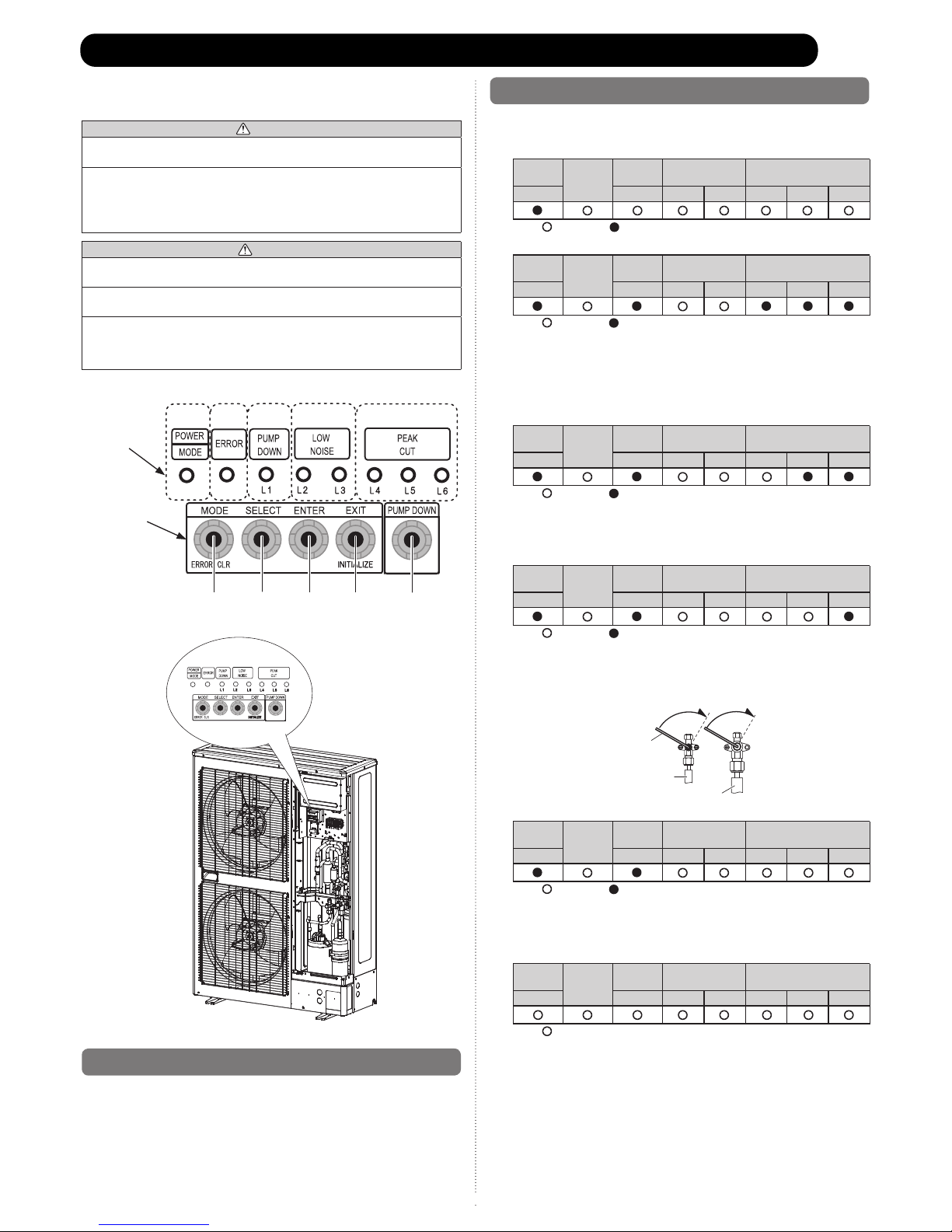
WARNING
Never touch electrical components such as the terminal blocks except the button on
the display board. It may cause a serious accident such as electric shock.
During the pump-down operation, make sure that the compressor is turned off
before you remove the refrigerant piping.
Do not remove the connection pipe while the compressor is in operation with 2-way
or 3-way valve open. This may cause abnormal pressure in the refrigeration cycle
that leads to breakage and even injury.
CAUTION
Perform the pump down operation before disconnecting any refrigerant pipe or
electric cable.
Collect refrigerant from the service port or the 3-way valve if pump down cannot be
performed.
In case of a group control system installation, do not turn the power off pump down is
completed in all outdoor units.
(Group control system installation described in “SPECIAL INSTALLATION
METHODS” in the installation manual of the indoor unit.)
Operate [PUMP DOWN] • button on the display board in the manner described
below.
LED display part
Button part
14.1. Preparation for pump down
Confirm that the power is off, and then open the service panel•
14.2. Pump down procedure
(1) Check the 3-way valves (both the liquid side and gas side) are opened.
(2) Turn the power on.
POWER
ERROR
PUMP
DOWN
LOW
NOISE
PEAK
CUT
MODE (L1) (L2) (L3) (L4) (L5) (L6)
Sign “ ”: Lights off, “ ”: Lights on
(3) Press [PUMP DOWN] button for 3 seconds or more after 3 minutes after power on.
LED display lights on as shown in the above figure, and the fans and the
compressor start operating.
If the [PUMP DOWN] button is pressed while the compressor is operating, the •
compressor will stop, then start again in about 3 minutes.
(4) LED display will change as shown below about 3 minutes after the compressor
starts. Fully close the 3-way valve on the liquid pipe side at this stage.
If the valve on the liquid pipe side is not closed, the pump down cannot be •
performed.
(5) When LED display changes as shown in the below figure, close the 3-way valve on
the gas pipe side tightly.
If the valve on the gas pipe side is not closed, refrigerant may flow into the piping•
after the compressor stops.
Step (5)
Closing direction
Step (4)
Hexagon wrench
Liquid pipe
Gas pipe
Closing direction
(6) LED display changes after 1 minute as shown in the figure below
Fans and compressor stop automatically.
If the pump down is successfully completed (the above LED display is shown), the •
outdoor unit remains stopped until the power is turned off.
(7) Turn the power off.
PUMP DOWN is completed.
(Note)
To stop pump down, press the [PUMP DOWN] button again.•
To start the pump down again after the compressor is automatically stopped due to an •
error, turn the power off and open the 3-way valves. Wait 3 minutes, turn the power on
and start the pump down again.
When starting the operation after completion of the pump down, turn the power off, •
and then open the 3-way valves. Wait 3 minutes, turn the power on and perform a test
run in the “COOL” operation mode.
If an error occurs, recover the refrigerant from service port.•
SW1 SW2 SW3 SW4 SW5
POWER
ERROR
PUMP
DOWN
LOW
NOISE
PEAK
CUT
MODE (L1) (L2) (L3) (L4) (L5) (L6)
Sign “ ”: Lights off, “ ”: Lights on
POWER
ERROR
PUMP
DOWN
LOW
NOISE
PEAK
CUT
MODE (L1) (L2) (L3) (L4) (L5) (L6)
Sign “ ”: Lights off, “ ”: Lights on
POWER
ERROR
PUMP
DOWN
LOW
NOISE
PEAK
CUT
MODE (L1) (L2) (L3) (L4) (L5) (L6)
Sign “ ”: Lights off, “ ”: Lights on
POWER
ERROR
PUMP
DOWN
LOW
NOISE
PEAK
CUT
MODE (L1) (L2) (L3) (L4) (L5) (L6)
Sign “ ”: Lights off, “ ”: Lights on
POWER
ERROR
PUMP
DOWN
LOW
NOISE
PEAK
CUT
MODE (L1) (L2) (L3) (L4) (L5) (L6)
Sign “ ”: Lights off
01-17
1-14. PUMP DOWN
Page 21
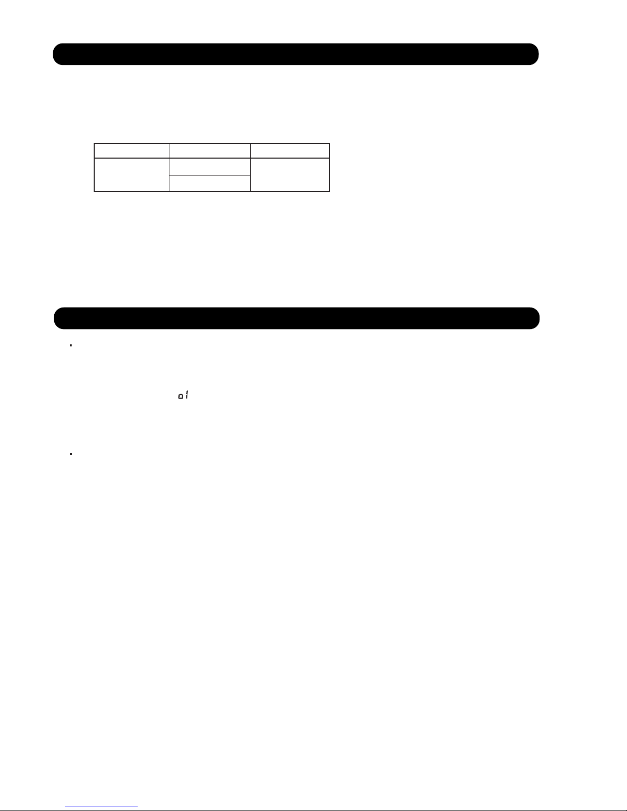
1-15. COMPRESSOR PREHEATING
01-18
When the outdoor temperature is lower than 20°C and the all operation mode has been
stopped for 30 minutes, power is applied to the compressor and the compressor is heated.
(By heating the compressor, warm air is quickly discharged when operation is started.)
When operation was started and when the outdoor temperature rises to 26°C or greater,
preheating is ended.
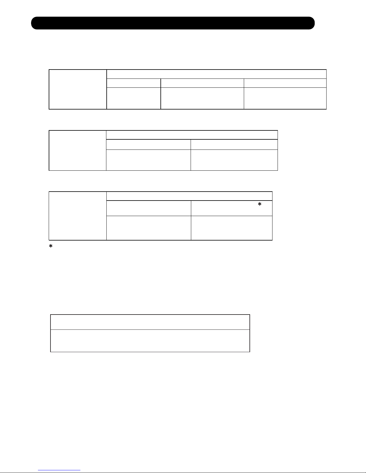
1-16. 10°C HEAT OPERATION (For AB type)
10°C HEAT operation functions by pressing 10°C HEAT button on the remote controller.
10°C HEAT operation is almost the same operation as below settings.
Mode Heating
Setting temperature 10°C
Fan mode AUTO
( Table8 )
1-17. ECONOMY OPERATION
The ECONOMY operation functions by pressing ECONOMY button on the remote controller.
The ECONOMY operation is almost the same operation as below settings.
Mode Cooling/ Dry Heating
Target temperature Setting temp.+1°C Setting temp.-1°C
( Table9 )
Page 22
01-19
1-18. DEFROST OPERATION CONTROL
1. CONDITION OF STARTING THE DEFROST OPERATION
Integratingdefrost
(Constant monitoring)
If the compressor continuous operation time is less than 10 minutes,
the OFF number of the compressor is counted.
If any defrost operated, the compressor OFF count is cleared.
2. CONDITION OF THE DEFROST OPERATION COMPLETION
Defrost operation is released when the conditions becomes as shown in Table 13.
( Table 13 : Condition of defrost release )
Release Condition
Outdoor heat exchanger temperature is higher than 10°C
or
Compressor operation time has passed 15 minutes.
The defrost operation starts as shown in the following Table 10, 11, and 12.
From 2nd and later
defrost after
starting operation
Less than 35 minutes More than 35 minutes
Does not operate
Compressor integrating operation time
( Table 10 : Condition of 1st defrost operation)
1st defrost
after
starting operation
Compressor integrating operation time
Less than 22 minutes More than 22 minutes More than 62 minutes
Does not operate
Outdoor heat exchanger temperature
Below -9°C
Outdoor heat exchanger temperature
Below -10°C
Outdoor heat exchanger temperature
Below -5°C
More than 240 minutes
( For long continuous operation )
Less than 10 minutes
( For intermittent operation )
Compressor integrating operation time
Outdoor heat exchanger temperature
Below -3°C
OFF count of the compressor
40 times
( Table 12 : Condition of Integrating defrost operation)
( Table 11 : Condition of 2nd defrost operation)
Page 23
01-20
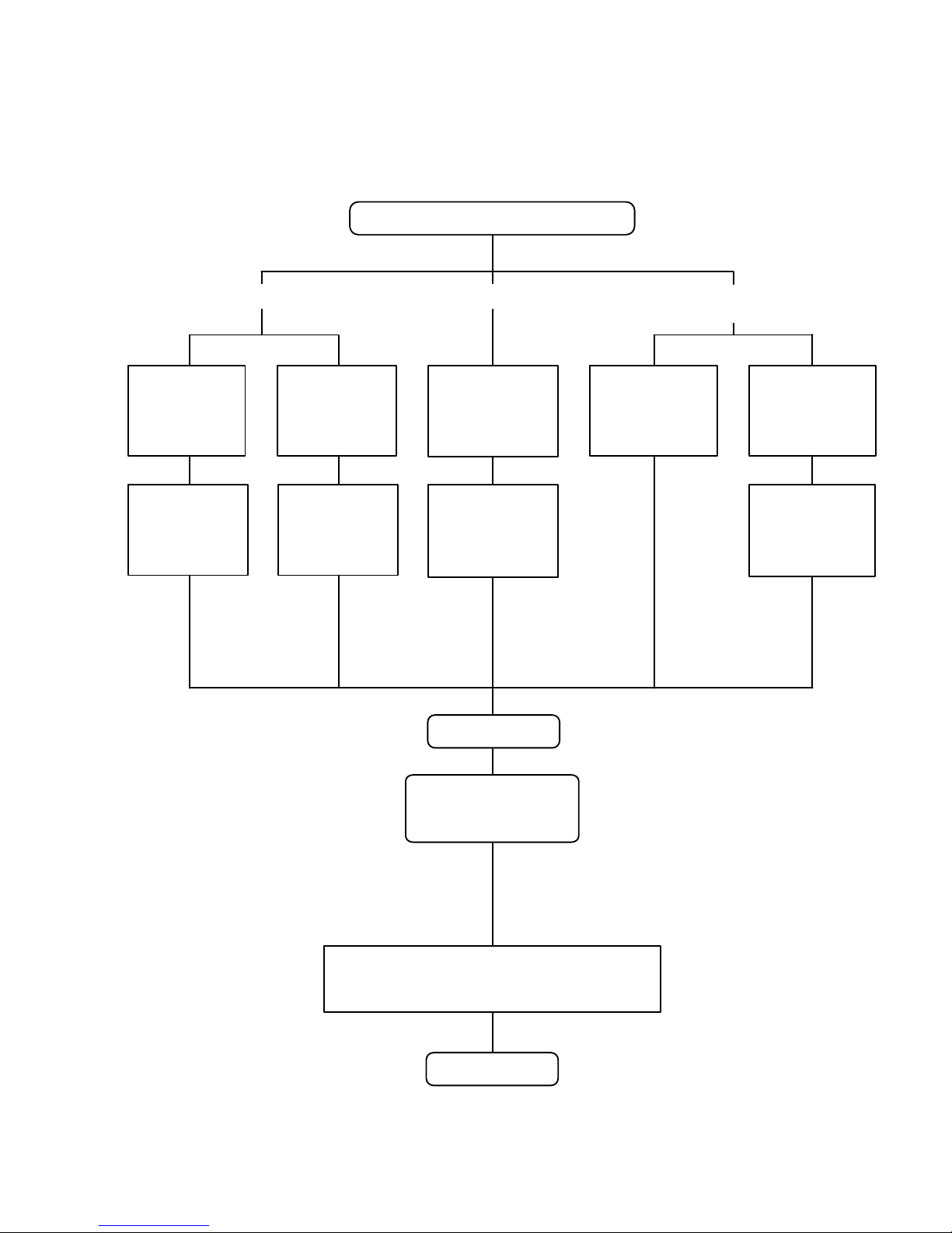
3. Defrost Flow Chart
The defrosting shall proceed by the integrating operation time, outdoor temperature
and outdoor heat exchanger temperature as follows.
(Not defrosted for 10 minutes)
Heating operation start : Compressor ON
Outdoor heat exchanger temperature: Over 10°C
or
Compressor ON time: Maximum 15 minutes
Defrost end
Compressor
integrating
operation:
Over 22 minutes
Compressor
integrating
operation:
Over 62 minutes
Outdoor
heat exchanger
temperature:
Below - 9°C
Outdoor
heat exchanger
temperature:
Below - 5°C
Compressor
integrating
operation:
Over 35 minutes
2nd and later defrost
Compressor : OFF
Outdoor fan motor : OFF
30 sec later 4-way valve : OFF
36 sec later compressor : ON
Compressor
integrating
operation:
Over 240 minutes
Integrating defrost
(Constant monitoring)
Defrost Indicator:
[Operation lamp]
7 sec ON / 2 sec OFF
Defrost start
Outdoor
heat exchanger
temperature:
Below - 10°C
Outdoor
heat exchanger
temperature:
Below - 3°C
Compressor
OFF count :
40 times
1st defrost
Page 24

1-19. OFF DEFROST OPEARTION CONTROL
01-21
1. OFF DEFROST OPERATION CONDITION
When operation stops in the [Heating operation] mode, if frost is adhered to the outdoor unit heat
exchanger, the defrost operation will proceed automatically. In this time, if indoor unit operation
lamp flashes slowly (7 sec ON / 2 sec OFF), the outdoor unit will allow the heat exchanger to defrost,
and then stop.
In heating operation, the outdoor heat exchanger temperature is less than -4°C,
and compressor operation integrating time lasts for more than 30 minutes,
and compressor operation contiguous time lasts for more than 10 minutes.
OFF Defrost Flow Chart
Heating operation stop
Outdoor heat exchanger temperature :
Below -4°C
and
Compressor integrating operation :
Over 30 minutes
and
Compressor contiguous operation:
Over 10 minutes
Defrost start
Defrost Indicater:
[Operation lamp]
7 sec ON / 2 sec OFF
Outdoor heat exchanger temperature : Over 10°C
or
Compressor ON time : Maximum 15 minutes
Defrost end
2. OFF DEFROST RELEASE CONDITION
Release Condition
Outdoor heat exchanger temperature is higher than 10°C
or
Compressor operation time has passed 15 minutes.
( Table 14 : OFF Defrost Release Condition )
OFF defrost operation is released when the conditions becomes as shown in Table 14.
Page 25
1-20. VARIOUS PROTECTIONS
01-22
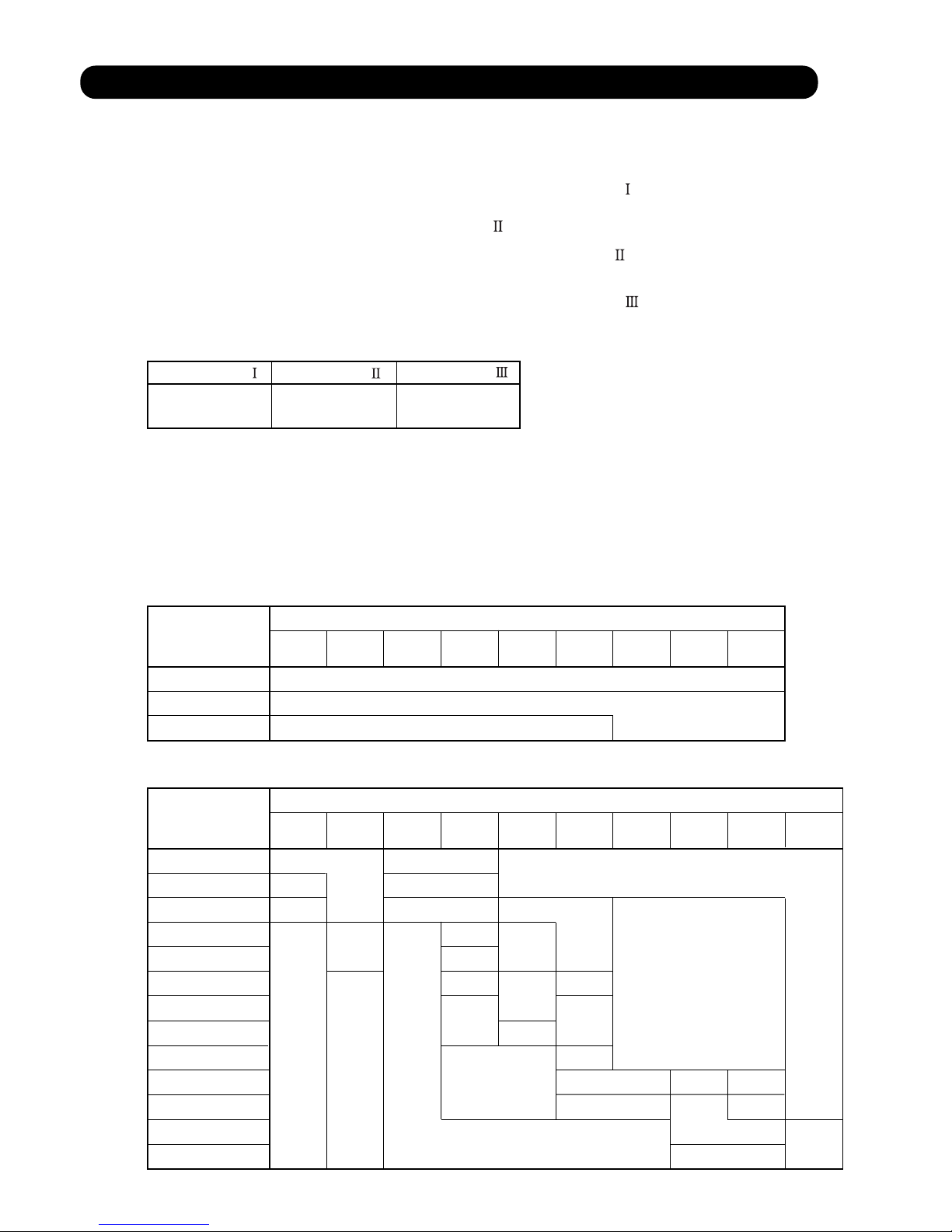
1. DISCHARGE GAS TEMPERATURE OVERRISE PREVENSION CONTROL
The discharge gas thermosensor (discharge thermistor : Outdoor side) will detect discharge gas
temperature.
104°C 101°C 110°C
When the discharge temperature becomes higher than Temperature ,the compressor frequency
is decreased 14rps, and it continues to decrease the frequency for 14rps every 120 seconds until
the temperature becomes lower than Temperature .
When the discharge temperature becomes lower than Temperature , the control of
the compressor frequency is released.
When the discharge temperature becomes higher than Temperature ,the compressor is stopped
and the indoor unit LED starts blinking.
(Table15 : Discharge Temperature Over Rise Prevension Control / Release Temperature)
Temperature
Temperature
Temperature
[ Heating ]
[ Cooling ]
T0 > 50°C
=
T0: Outdoor temperature
Outdoor unit fan speed (rpm)
T0 < -15°C
50°C > T0 > 46°C
=
46°C > T0 > 40°C
=
40°C > T0 > 38°C
=
38°C > T0 > 31°C
=
31°C > T0 > 19°C
=
19°C > T0 > 13°C
=
13°C > T0 > 7°C
=
7°C > T0 > 0°C
=
0°C > T0 > -5°C
=
-5°C > T0 > -10°C
=
-10°C >T0 > -15°C
=
850/800 780/750 750/700 540/520 360/340 290/270 480/ 0 400/ 0 350/ 0 280/ 0
12.5/12.0 6.5/ 6.0
5.0/ 4.5
8.0/ 7.5
9.0/ 8.5
9.0/ 8.5
10.0/ 9.5
10.0/ 9.5
10.0/ 9.5 6.0/ 5.5
10.5/10.0
12.5/12.0
12.0/11.5 10.0/ 9.5
12.5/12.0
13.0/12.5
14.5/14.0
15.5/15.0 11.5/11.0
11.0/10.5
13.5/13.0
13.5/13.0
14.5/14.0
15.0/14.5
15.5/15.0
16.0/15.5
13.5/13.0
16.5/16.0
17.5/17.0
19.5/19.0 19.0/18.5 16.5/16.0
T0 > 20°C
=
T0: Outdoor temperature
Outdoor unit fan speed (rpm)
T0 < 12°C
20°C > T0 > 12°C
=
900/880 850/830 780/750 720/700 570/550 500/480 370/350 300/280 220/200
16.5/16.0
14.5/14.0
19.5/19.0
The compressor frequency is controlled so that the outdoor unit input current does not exceeds
the current limit value that was set up with the outdoor temperature.
The compressor frequency returns to the designated frequency of the indoor unit at the time
when the frequency becomes lower than the release value.
(Table 16 : Current Release Operation Value / Release Value)
2. CURRENT RELEASE CONTROL
Page 26

01-23
3. ANTIFREEZING CONTROL (Cooling and Dry mode)
The compressor frequency is decrease on cooling & dry mode when the indoor heat exchanger
temperature sensor detects the temperature lower than Temperature .
Then, the anti-freezing control is released when it becomes higher than Temperature .
(Table 17 : Anti-freezing Protection Operation / Release Temperature)
Outdoor temperature
Over than 10°C *1
or 12°C *2
Less than 10°C *1
or 12°C *2
*1. When the temperature rises.
*2. When the temperature drops.
4°C
7°C
13°C
Temperature Temperature
68°C
63°C
4. COOLING PRESSURE OVER RISE PROTECTION
On cooling mode, the compressor frequency is controlled as following based on the
detection value of the outdoor heat exchanger temperature sensor.
Outdoor heat exchange
temperature
(Fig.10 : Cooling Pressure Over Rise Protection Control)
Compressor is OFF
The compressor frequency is
decreased 7rps every 120seconds.
Release of protection
5. LOW PRESSURE PROTECTION CONTROL (For Cooling mode)
<After the compressor start-up and 10 minutes has passed>
<After the compressor start-up and 1 minute has passed>
(a).The detected value of pressure sensor is 0.02MPaG or less,
continues for 5 minutes, the compressor is stopped.
(b). When 7 minutes has passed and low pressure sensor detects
value is more than 0.05MPaG after the protection stop by (a),
the compressor restarts.
(c).When the protection (a) operates 5 times within 2 hours after the
restart by (b),
the error is displayed and the compressor stops. [Permanent stop]
0.78MPaG
0.68MPaG
Release of protection
-8 rps every 1 minute
Pressure
(Fig 12 : Anti freezing protection)
(a).When the low pressure value becomes 0.68MPaG or less
continues for 1 minute, the compressor speed -8 rps.
(b). When the low pressure value becomes 0.68MPaG or less
after the protection (a), the compressor continues speed -8 rps
every 1 minute until the detected value becomes more than
0.68MPaG.
(c). When the low pressure value becomes more than 0.78MPaG,
this protection is released.
0.05MPaG
0.02MPaG
Release of protection
Hold
Compressor stop
Pressure
(Fig 11 : Low pressure protection 1)
Hold
5-1. Low Pressure Protection 1
5-2. Low Pressure Protection 2
Page 27

01-24
6. HEATING OVERLOAD PROTECTION
On heating mode, the compressor frequency is controlled as following based on the
detection value of the pressure sensor.
(Fig.13 : Heating Overload Protection Control)
4.1MPa
(65°C)
Compressor is OFF
The compressor frequency is
decreased 10rps every 60 seconds.
3.3MPa
(55°C)
3.0MPa
(50°C)
2.8MPa
(48°C)
Stable range
Release
The compressor frequency is
decreased 2rps every 60 seconds.
Release
- 20°C
Cooling
Heating
1-21. COMPRESSOR STOP CONTROL
When the detection value of outdoor temperature sensor is lower than temperature
in the table below, the compressor is stopped.
(Table 18 : Operation temperature of compressor stop control)
Operation
temperature
Temperature
The fan motor for Fresh Air is operated in synchronization with the indoor fan operation
as shown in Fig.14.
1-22. FRESH AIR CONTROL
(Fig.14 : Fresh Air control)
ON
OFF
ON
OFF
Fan motor
(Indoor unit)
Control signal
(for Fresh Air)
12V
Condensing pressure
(Indoor heat ex. temp.)
4.1MPa
(65°C)
Compressor is OFF
The compressor frequency is
decreased 15rps every 120 seconds.
3.5MPa
(57°C)
3.3MPa
(55°C)
3.0MPa
(50°C)
Stable range
Release
The compressor frequency is
decreased 2rps every 120 seconds.
Release
Condensing pressure
(Indoor heat ex. temp.)
[AR*G45/54LHTA] [Other models]
Page 28

01-25
Operation mode : Heating mode
Compressor : ON
Indoor fan : ON
Model type : Heat pump
1-23. EXTERNAL ELECTRICAL HEATER CONTROL (For AR type)
(Fig 15 : External Electrical Heater control)
When the room
temperature rises
When the room
temperature drops
Ts : Setting temperature
Heater : OFF
Heater : ON
Heater : OFF
Ts -10°C
Ts -1°C
Ts -3°C
Ts -12°C
The External Electrical Heater operates when it meets all the following conditions.
1-24. LOW NOISE OPERATION
Low Noise mode
LEVEL 1
LEVEL 2
LEVEL 3
Cooling
Heating
Cooling
Heating
Cooling
Heating
Outdoor fan speed
(Upper / Lower)
[rpm]
Compressor speed [rps]
The compressor speed and the outdoor unit fan speed are limited to reduce the operation noise
by External Input.
During the LOW NOISE OPERATION,
"CURRENT OVERLOAD OPERATION", "ECONOMY OPERATION" and "PEAK CUT OPERATION"
are effective, and the outdoor unit operates by lowest current of them.
However, during the DEFROST OPERATION, the compressor operates by the speed
for DEFROST OPERATION.
( Table 19 : Detail of Low Noise Operation )
540 / 520
570 / 550
540 / 520
570 / 550
540 / 520
570 / 550
68
75
54
62
48
54
75
85
58
68
48
54
*The performance drops when operating in the LOW NOISE OPERATION.
AO*G45L AO*G54L
1-25. PEAK CUT OPERATION
(Table 20 : Outline of Peak Cut Operation )
LEVEL 1 LEVEL 2 LEVEL 3 LEVEL 4
100%
75%50%
Forced
thermostat-OFF
The Current Value is limited to reduce the power consumption by External Input.
During the PEAK CUT OPERATION,
"CURRENT OVERLOAD OPERATION", "ECONOMY OPERATION" and "LOW NOISE OPERATION"
are effective, and the outdoor unit operates by lowest current of them.
However, this function becomes invalid during DEFROST OPERATION.
PEAK CUT LEVEL
Peak Cut
For Rated Capacity
*Percentage is rated electrical power ratio.
Page 29

01-26
1-26. DRAIN PUMP OPERATION (For AU/ AR type)
1. When the compressor starts, the drain pump starts simultaneously.
2. The drain pump operates continuously for 3 minutes after the compressor is turned off.
3. When the compressor stops by the "Anti- freezing protection", the drain pump is turned off
in 1 hour after the compressor stops.
4. When the water level in the drain pan rises up and then the float switch functions:
The compressor, indoor and outdoor fan motor operation are stopped.
Drain pump operates continuously for 3 minutes after the float switch is turned off.
(Almost condensing water may be drained)
5. When the float switch turns ON continuously for 3 minutes, "FAILURE INDICATION" operates.
(It is necessary to turn off power for release it. )
6. When the float switch turns OFF less than 3 minutes, the unit starts Cooling operation.
1
2
1.When the water level in the drain pan rises up and then the float switch functions:
Drain pump operates continuously for 3 minutes after the float switch is turned off.
(Almost condensing water may be drained)
2. When the float switch turns ON continuously for 3 minutes, "FAILURE INDICATION" operates.
Thereafter, even if the float switch turns OFF, the "FAILURE INDICATION" is not released.
(It is necessary to turn off power for release it. )
1
During Cooling / Dry mode
3 minutes
ON
OFF
ON
OFF
Compressor
Drain Pump
3 minutes
3 minutes ST
ON
OFF
ON
OFF
ON
OFF
ON
OFF
Float Switch
Compressor
Indoor Fan
Drain Pump
3 minutes
ON
OFF
ON
OFF
Float Switch
Drain Pump
During Heating / Fan mode / Stop operation
<Float Switch turns OFF less than 3 minutes>
Less than 3 minutes
.
.
The indoor unit fan motor operates after the float switch is turned off.
3
(Fig 16 : Detail of Drain Pump Operation)
Page 30

01-27
1-27. DESCRIPTION OF DISPLAY UNIT
•
Display lamp
Function or operation method
(1) POWER / MODE
Green
Lights on while power on. Local setting in outdoor unit or
error code is displayed with blink.
(2) ERROR
Red
Blinks during abnormal air-conditioner operation.
(3) PUMP DOWN
(L1)
Orange
Lights on during pump down operation.
(4) LOW NOISE MODE
(L2, L3)
Orange
Lights on during “Low noise” mode when local setting is activated.
(Lighting pattern of L2 and L3 indicates low noise level)
(5) PEAK CUT
(L4, L5, L6)
Orange
Lights on during “Peak cut” mode when local setting is activated.
(Lighting pattern of L4, L5 and L6 indicates peak cut level)
SW1 SW2 SW3 SW4 SW5
(1) (2) (3) (4) (5)
LED DISPLAY
Various settings can be adjusted by changing Push switches on the board of the outdoor unit.
( Excerpt from the "INSTALATION MANUAL" )
Switch
Function or operation method
SW1 To switch between “Local setting” and “Error code display”.
SW2
To switch between the individual “Local settings” and the
“Error code displays”.
SW3
To fix the individual “Local settings ” and the “Error code displays”.
SW4
To return to “Operation status display”.
SW5 To start the pump down operation.
MODE
SELECT
ENTER
EXIT / INITIALIZE
PUMP DOWN
PUSH SWITCH
1-00. ERROR HISTORY MODE
1-27-1 Layout of Display Unit
Page 31

01-28
•
In this mode, the "Operation Condition" and "Error Code" can be displayed by Push Switch on outdoor unit PCB
LED
Power / Mode
LED
Display Item
Compressor frequency
Upper fan speed (Outdoor unit)
Lower fan speed (Outdoor unit)
EEV pulse
Pressure sensor value (Low pressure range)
Pressure sensor value (High pressure range)
Outdoor air temperature sensor value
Discharge temperature sensor value
Heat-exchanger temperature sensor value (Middle)
Current value
Present Value
Of
Each Item
1
Compressor accumulated time
(Table :21 Procedure for Present Value)
Procedure
Operation
Power
Mode
Error L1 L2 L6L5L4L3
1
2
3
4
During status display, press the MODE SWITCH 1 time.
(Status display : Outdoor unit is stopping and no error)
When the EXIT SWITCH is pressed, this mode ends
and returns to the status display.
Selecting display items can be done by pressing
the SELECT SWITCH. (Return to Procedure 3)
Press the ENTER SWITCH.
(Data is displayed by lighting LED. Refer to Table : 23)
When the POWER / MODE LED blinking 1 time,
press the ENTER SWITCH.
1
1
1
1
DATA
: Light ON: Light OFF : Blinking 1 : 1 Time Blinking
1-00. ERROR HISTORY MODE
1-27-2 Display mode
(Table :22 Display pattern)
: Light ON: Light OFF n : n Time Blinking
5
1
Press the SELECT SWITCH and adjust to DISPLAY ITEM
(from L1 to L3) that you want to confirm. (Refer to Table : 22)
ERROR
L1 L2 L3
: Blinking
Page 32

(Table 23 : Detail of LED Display Data)
: Light ON: Light OFF 1 : 1 Time Blinking
Item No,
Display Item
Power
Mode
Error L1 L2 L6L5L4L3
1
1
1
1
1
1
1
1
1
1
1
1
1
1
1
1
1
1
1
1
1
1
1
1
1
1
1
1
1
1
1
1
1
1
1
1
1
1
1
1
1
1
1
1
1
1
1
1
Compressor
Frequency
( 0 ~ 95rps )
Outdoor Unit Upper
Fan Speed
( 0 ~ 900rpm )
Outdoor Unit
Lower Fan Speed
( 0 ~ 900rpm )
EEV Pulse
( 0 ~ 480pulse )
Pressure sensor value
<Low pressure range>
( 0 ~ 2.1MPa )
Pressure sensor value
<High pressure range>
( 2.1 ~ 4.2MPa )
Check the Low Pressure
Range if it is displayed
[ ~ 2.1 ]
Check the High Pressure
Range if it is displayed
[ 1.81 ~ 2.1 ]
0
1 ~ 15
16 ~ 30
31 ~ 45
46 ~ 60
61 ~ 75
76 ~ 90
90 ~ 95
0
1 ~ 150
151 ~ 300
301 ~ 450
451 ~ 600
601 ~ 750
751 ~ 900
901 ~
0
1 ~ 150
151 ~ 300
301 ~ 450
451 ~ 600
601 ~ 750
751 ~ 900
901 ~
0
1 ~ 80
81 ~ 160
161 ~ 240
241 ~ 320
321 ~ 400
401 ~ 480
481 ~
~ 0.0
0.01 ~ 0.3
0.31 ~ 0.6
0.61 ~ 0.9
0.91 ~ 1.2
1.21 ~ 1.5
1.51 ~ 1.8
1.81 ~ 2.1
~ 2.1
2.11 ~ 2.4
2.41 ~ 2.7
2.71 ~ 3.0
3.01 ~ 3.3
3.31 ~ 3.6
3.61 ~ 3.9
3.91 ~ 4.2
01-29
1
2
3
4
5
6
Page 33

: Light ON: Light OFF 1 : 1 Time Blinking
Item No,
Display Item
Power
Mode
Error L1 L2 L6L5L4L3
1
1
1
1
1
1
1
1
1
1
1
1
1
1
1
1
1
1
1
1
1
1
1
1
1
1
1
1
1
1
1
1
1
1
1
1
1
1
1
1
Outdoor Air
Temperature
( -30 ~ 70°C )
Discharge
Temperature
( -30 ~ 120°C )
Heat-exchanger
Temperature
<Middle>
( -30 ~ 80°C )
Current ( 0 ~ 10A )
Compressor
Accumulated Time
( H )
~ -15
-15 ~ -5
-5 ~ 5
5 ~ 15
15 ~ 25
25 ~ 35
35 ~ 45
45 ~
~ 55
55 ~ 65
65 ~ 75
75 ~ 85
85 ~ 95
95 ~ 105
105 ~ 115
115 ~
~ 53
53 ~ 55
55 ~ 57
57 ~ 59
59 ~ 61
61 ~ 63
63 ~ 65
65 ~
~ 0.0
0.0 ~ 1.5
1.5 ~ 3.0
3.0 ~ 4.5
4.5 ~ 6.0
6.0 ~ 7.5
7.5 ~ 9.0
9.0 ~
0
0 ~ 10000
10000 ~ 20000
20000 ~ 30000
30000 ~ 40000
40000 ~ 50000
50000 ~ 60000
60000 ~
7
8
9
01-30
<Round up by 1hour>
10
11
Page 34

01-31
1-00. ERROR HISTORY MODE
•
In this mode, the history of abnormality that occurred in the past can be confirmed.
(Table : 24 Procedure for History Mode )
Procedure Operation
Power
Mode
1
2
3
4
During status display, press the MODE SWITCH 2 times.
(Status display : Outdoor unit is stopping and no error)
When the EXIT SWITCH is pressed, this mode
ends and returns to the status display.
Selecting display items can be done by pressingthe
SELECT SWITCH. (Return to Procedure 3)
Press the ENTER SWITCH, Error code is displayed by
lighting LED. (Refer to Table : 26)
When the POWER / MODE LED blinking 2 times,
press the ENTER SWITCH.
: Light ON: Light OFF : Blinking 2 : 2 Times Blinking
n : n Times Blinking
1-27-3 Error history mode
Error L1 L2 L6L5L4L3
2
2
2
2
2
5
Press the SELECT SWITCH and adjust to DISPLAY ITEM
(from L1 to L3) that you want to confirm. (Refer to Table : 25)
n n
DATA
LED
Power / Mode
LED
Display Item
ERROR
L1 L2 L3
(Table :25 Display pattern)
: Light ON: Light OFF n : n Time Blinking
: Blinking
Newest error code
Error code before 1 time
Error Code
2
Error code before 2 times
Page 35

01-32
1-00. ERROR HISTORY MODE
1-27-4 ERROR CHECK MODE
•
In this mode, abnormality that is occurring now can be confirmed.
Confirm Chapter 2 " TROUBLE SHOOTING" in detail.
(Table : 27 Procedure for Error Check Mode )
Procedure Operation
Power
Mode
1
2
3
Check that the "ERROR" LED blinking (Hi-speed),
and then short press the ENTER SWITCH 1 time.
When reset of the ERROR history,
and then long press the MODE SWITCH.
Error code is displayed by lighting LED.
(Refer to Table : 26)
: Light ON: Light OFF 2 : 2 Times Blinking
n : n Times Blinking
Error L1 L2 L6L5L4L3
2
n
Blinking
Hi-speed
n
DATA
2 2 2 2 2 2 2 2
After the error reset ,all LED is blinking and erased the all error history .
After this, ERROR LED is off and will normal display.
Error Contents
Power
Mode
Error
Serial forward transfer error(after operation)
2
2
2
2
2
2
2
2
2
2
2
1
1 ~ : 1~ 15 Times Blinking 15
(Table : 26 Error Code)
L1 L2 L6L5L4L3
IPM Error
Indoor Unit Error
Inverter Error
Over Current Error
Discharge Thermistor Error
Outdoor Thermistor Error
Heat Sink Thermistor Error
Current sensor Error
Pressure sensor Error
Heat Ex. Liquid Middle
Thermistor Error
Compressor Thermistor Error
Compressor Control Error
Outdoor Unit Fan Motor 1 Error
Outdoor Unit Fan Motor 2 Error
4-way Valve Error
Discharge Temp. Error
Compressor Temp. Error
Low Pressure Error
2
2
2
2
2
2
2
2
2
2
2
1
1
1
5
6
3
6
5
7
1
7
2
7
3
7
3
7
4
7
7
8
4
8
6
8
6
9
4
9
5
9
7
9
8
9
9
10
1
10
3
10 5
15
Serial forward transfer error(during operation)
Heat Ex. Liquid Outlet
Thermistor Error
High Pressure Switch Error
: Light ON: Light OFF 2 : 2 Times Blinking
Page 36

Page 37

2 . TROUBLE SHOOTING
R410A
Cassette/ Duct/ Ceiling type
INVERTER
Page 38

Indoor Room Thermistor Error
Wired Remote Controller
Communication Error
Error Contents
Trouble
shooting
02-01
2-1 ERROR DISPLAY
2-1-1 INDOOR UNIT AND WIRED REMOTE CONTROLLER DISPLAY
Serial Communication Error
Indoor Unit Fan Motor1 Error
Indoor Heat Ex. Thermistor Error
Drainage Error
1,2
3
4
5
6
7
8
9
1- 9
10
11
12
13
14
15
16
IPM Error
Error
Code
11
12
39
41
42
51
53
59
5U
63
65
71
72
73
74
77
Fan Motor Driving Circuit Error
Indoor Unit Error
Inverter Error
Indoor Unit Fan Motor2 Error
Error Contents
Trouble
shooting
17
18
19
20
21
22
23
24
25
26
Error
Code
84
86
94
95
97
98
99
A1
A3
A5
Over Current Error
Discharge Thermistor Error
Outdoor Thermistor Error
Heat Sink Thermistor Error
Current sensor Error
Pressure sensor Error
Heat Ex. Liquid Outlet
Thermistor Error
Compressor Thermistor Error
When "Er" in Temperature Display is displayed, inspection of the air conditioning system is necessary.
Please consult authoilzed service personnel.
1. SELF - DIAGNOSIS
SUMOTUWETH FR
SA
Unit number (usually 0)
Error code
ex. Self-diagnosis check
Compressor Control Error
Outdoor Unit Fan Motor 1 Error
Outdoor Unit Fan Motor 2 Error
4-way Valve Error
Discharge Temp. Error
Compressor Temp. Error
Low Pressure Error
Page 39

02-02
2. ERROR CODE HISTORY DISPLAY
Up to 16 memorized error codes may be displayed for the indoor unit connected to the remote controller.
1. Stop the air conditioner operation.
2. Press the SET TEMPERATURE buttons , simultaneously for 3 seconds
or more to start the self-diagnosis.
4. Press the SET TEMPERATURE buttons , simultaneously for 3 seconds or more
or there is no key input for 60 seconds to stop the display.
3. Press the SET TEMPERATURE button to select the error history number.
SU MOTU WETH FR SA
Error code
Error history number
0 1 2 3 4 5 6 7
F E d c b A 9 8
Lower
Raise
Page 40

Trouble shooting 1
OUTDOOR UNIT Error Method:
Detective Actuators: Detective details:
Forecast of Cause:
OK
Indicate or Display:
Refer to error code table.
YESYES
NO
Serial Communication Error
(Serial Reverse Transfer Error)
Outdoor unit Main PCB
Outdoor unit Fan motor
1. Connection failure 2. External cause 3. Main PCB failure 4. Active filter module failure
5. Transistor PCB (IPM) failure 6. Filter PCB failure 7. Outdoor unit Fan motor failure
Check Point 1-1 : Reset the power and operate
Does error indication reappear?
Check Point 1-2 : Check external cause such as noise
Check if the ground connection is proper.
Check if there is any equipment that causes harmonic wave
near the power cable (Neon light bulb or any electronic
equipment which causes harmonic wave).
Check Point 2 : Check connection
Check any loose or removed connection line of
between indoor unit and outdoor unit.
>> If there is an abnormal condition, correct it by
referring to Installation Manual or Data &
Technical Manual.
Check connection condition in control unit.
(If there is loose connector, open cable or mis-wiring)
Check Point 3 : Check the voltage of power supply
Check the voltage of power supply
>> Check if AC198V(AC220V-10%) - 264V(AC240V+10%) appears
at outdoor unit terminal L - N.
When the indoor unit cannot receive the serial signal from Outdoor unit
more than 2minutes after power ON, or the indoor unit cannot receive
the serial signal more than 15seconds during normal operation.
02-04
2-2 TROUBLE SHOOTING WITH ERROR CODE
OK
Check Point 4 : Check serial signal (Reverse transfer signal)
Check serial signal (Reverse transfer signal)
>> Check if indicated value swings between AC90V and AC270V at outdoor unit terminal 1 - 3.
>> If it is abnormal, Check the parts as follows.
- Outdoor unit fan motor (PARTS INFORMATION 5)
- Active filter module (PARTS INFORMATION 4)
- Transistor PCB (IPM) (PARTS INFORMATION 7)
- Filter PCB (Check the wire of CN110)
>> If Outdoor fan motor is abnormal, replace Outdoor unit fan motor and Main PCB.
>> If Active filter module or IPM is abnormal, replace it.
>> If the parts are normal, replace Main PCB.
1
2
3
L
N
RED
WHITE
BLACK
BLACK
WHITE
+
-
Page 41

Trouble shooting 2
INDOOR UNIT Error Method:
Detective Actuators: Detective details:
Forecast of Cause:
OK
Indicate or Display:
Refer to error code table.
YESYES
NO
OK
Serial Communication Error
(Serial Forward Transfer Error)
Indoor unit Controller PCB
1. Connection failure 2. External cause 3. Controller PCB failure
Check Point 1-1 : Reset the power and operate
Does error indication reappear?
Check Point 1-2 : Check external cause such as noise
Check if the ground connection is proper.
Check if there is any equipment that causes harmonic wave
near the power cable (Neon light bulb or any electronic
equipment which causes harmonic wave).
Check Point 2 : Check connection
Check any loose or removed connection line of
between indoor unit and outdoor unit.
>> If there is an abnormal condition, correct it by
referring to Installation Manual or Data &
Technical Manual.
Check connection condition in control unit.
(If there is loose connector, open cable or mis-wiring)
Check Point 3 : Check the voltage of power supply
Check the voltage of power supply
>> Check if AC198V(AC220V-10%) - 268V(AC240V+10%) appears
at outdoor unit terminal L - N.
Check Point 4 : Check serial signal (Forward transfer signal)
Check serial signal (Forward transfer signal)
>> Check if indicated value swings between AC30V and AC130V at outdoor unit terminal 2 - 3.
>> If it is abnormal, replace Controller PCB.
When the outdoor unit cannot properly receive the serial signal from
indoor unit for 10 seconds or more.
02-05
1
2
3
L
N
RED
WHITE
BLACK
BLACK
WHITE
+
-
Page 42

Trouble shooting 3
INDOOR UNIT Error Method:
Detective Actuators: Detective details:
Forecast of Cause:
Check Point 2 : Check Wired Remote Controller and Controller PCB
Check Point 1 : Check the connection of terminal
OKOK
Indicate or Display:
Wired Remote Controller
Communication Error
Indoor unit Controller PCB
Wired Remote Controller
1. Connection failure 2. Wired Remote Controller failure 3. Controller PCB failure
Check & correct the followings.
Check the connection of terminal between Wired Remote Controller and indoor unit,
and check if there is a disconnection of the cable.
When the indoor unit cannot properly receive the signal from
Wired Remote Controller for 1 minute or more.
02-06
Refer to error code table.
>> If it is DC12V, Remote Control is failure. (Controller PCB is normal) >> Replace Remote Control
>> If it is DC 0V, Controller PCB is failure. (Check Remote Control once again) >> Replace Controller PCB
Check Voltage at CN14 (AU*G45/54LRLA, AR*G45LMLA, AB*G45LRTA), CN6 (AR*G45/54LHTA)
of Controller PCB. (terminal 1-3) (Power supply to Remote Control)
Page 43

Trouble shooting 4
INDOOR UNIT Error Method:
Indicate or Display:
Detective Actuators: Detective details:
Forecast of Cause :
Fan Motor Drive Circuit Error
Indoor Unit Power Supply PCB
When a momentary power cut off.
When do not start fan motor.
1. External cause 2. Conenection of connector failure 3. Power Supply PCB failure
Check Point 3 : Replace Power supply PCB
If Check Point 1, 2 do not improve the symptom, replace Power supply PCB.
02-07
Refer to error code table.
OKOK
Check Point 2 : Check connection of Connector
Check if connector is removed.
Check erroneous connection.
Check if cable is open.
>>Upon correcting the removed connector or mis-wiring, reset the power.
Check Point 1 : Check external cause at Indoor and Outdoor (Voltage drop or Noise)
Instant drop : Check if there is a large load electric apparatus in the same circuit.
Momentary power failure : Check if there is a defective contact or leak current
in the power supply circuit.
Noise : Check if there is any equipment causing harmonic wave near electric line.
(Neon bulb or electric equipment that may cause harmonic wave)
Check the complete insulation of grounding.
OKOK
Page 44

Detective Actuators:
Indoor Unit Controller PCB Circuit
Indoor Temperature Thermistor
Detective details:
Indoor unit thermistor is open or short is detected always.
Forecast of Cause :
1. Connector failure connection 2. Thermistor failure 3. Controller PCB failuer
Check Point 2 : Remove connector and check Thermistor resistance value
Thermistor Characteristics (Rough value)
If Thermistor is either open or shorted, replace it and reset the power.
Check Point 1 : Check connection of Connector
Check if connector is loose or removed
Check erroneous connection
Check if thermistor cable is open
>>Reset Power when reinstalling due to removed connector or incorrect wiring.
6.58.0
10.012.515.820.225.933.6
4.355.3Resistance value (k )
OK
OK
02-08
Trouble shooting 5
INDOOR UNIT Error Method:
Indicate or Display:
Indoor Room Thermistor Error
Refer to error code table.
Temperature (°C )
Temperature (°C )
0
40 45
5
44.058.2
-10 -5 10 15 20 25
30 35
Resistance value (k )
Check Point 3 : Check voltage of Controller PCB (DC5.0V)
Make sure circuit diagram of indoor unit and check terminal voltage at thermistor (DC5.0V)
If the voltage does not appear, replace Controller PCB.
H/E (MID) Thermistor
Room Temp. Thermistor
AR*G45LMLA
BLACK
BLACK
121
2
1 1
2 2
1 1
2 2
CN5
CN8
GRAY
GRAY
1
2
CN7
H/E (MID) Thermistor
Room Temp. Thermistor
AR*G45/ 54LHTA
BLACK
BLACK
121
2
1 1
2 2
CN8
GRAY
GRAY
CN7
H/E (MID) Thermistor
Room Temp. Thermistor
AU*G45/ 54LRLA
RED
RED
121
2
1 1
2 2
CN5
CN8
BLACK
BLACK
1
2
CN7
121
2
121
2
1
2
H/E (MID) Thermistor
Room Temp. Thermistor
BLACK
BLACK
CN5
CN8
GRAY
GRAY
CN7
BLACK
BLACK
AB*G45LRTA
Page 45

Thermistor Characteristics (Rough value)
If Thermistor is either open or shorted, replace it and reset the power.
Detective Actuators:
Indoor Unit Controller PCB
Heat Exchanger (MID) Thermistor
Detective details:
Indoor unit thermistor is open or short is detected always.
Forecast of Cause :
1. Connector failure connection 2. Thermistor failure 3. Controller PCB failuer
Check Point 1 : Check connection of Connector
Check if connector is loose or removed
Check erroneous connection
Check if thermistor cable is open
>>Reset Power when reinstalling due to removed connector or incorrect wiring.
OK
Check Point 2 : Remove connector and check Thermistor resistance value
02-09
Trouble shooting 6
INDOOR UNIT Error Method:
Indicate or Display:
Indoor Heat Ex. Thermistor Error
Refer to error code table.
31.739.649.7
62.980.3103.3134.2176.0
17.120.825.6Resistance value (k )
Temperature (°C )
Temperature (°C )
0
40 45 50
14.15511.66010.4
63
5 10
1131.9
-30
579.6
-20
312.3
-10
233.2
-5 15 20
25 30 35
Resistance value (k )
OK
Check Point 3 : Check voltage of Controller PCB (DC5.0V)
Make sure circuit diagram of indoor unit and check terminal voltage at thermistor (DC5.0V)
If the voltage does not appear, replace Controller PCB.
H/E (MID) Thermistor
Room Temp. Thermistor
AR*G45LMLA
BLACK
BLACK
121
2
1 1
2 2
1 1
2 2
CN5
CN8
GRAY
GRAY
1
2
CN7
H/E (MID) Thermistor
Room Temp. Thermistor
AR*G45/ 54LHTA
BLACK
BLACK
121
2
1 1
2 2
CN8
GRAY
GRAY
CN7
H/E (MID) Thermistor
Room Temp. Thermistor
AU*G45/ 54LRLA
RED
RED
121
2
1 1
2 2
CN5
CN8
BLACK
BLACK
1
2
CN7
121
2
121
2
1
2
H/E (MID) Thermistor
Room Temp. Thermistor
BLACK
BLACK
CN5
CN8
GRAY
GRAY
CN7
BLACK
BLACK
AB*G45LRTA
Page 46

02-10
Trouble shooting 7
INDOOR UNIT Error Method:
Indicate or Display:
Indoor Unit Fan Motor1 Error
Refer to error code table.
Detective Actuators:
Detective details:
Forecast of Cause:
Check Point 1 : Check rotation of Fan
Check Point 2 : Check ambient temp. around motor
OK
OK
OK
Indoor unit Power Supply PCB
Indoor unit fan motor
1. Fan rotation failure 2. Fan motor winding open 3. Motor protection by surrounding temperature rise
4. Power Supply PCB failure 5. Indoor unit fan motor failure
Rotate the fan by hand when operation is off.
(Check if fan is caught, dropped off or locked motor)
>>If Fan or Bearing is abnormal, replace it.
Check excessively high temperature around the motor.
(If there is any surrounding equipment that causes heat)
>>Upon the temperature coming down, restart operation.
When the condition that actual frequency of Indoor Fan is
below 1/3 of target frequency is continued more than 56 seconds.
Check Point 4 : Replace Power Supply PCB
If Check Point 1- 3 do not improve the symptom, replace Power Supply PCB.
Check Point 3 : Check Indoor unit fan motor
Check Indoor unit fan motor. (PARTS INFORMATION 4)
>>If Indoor unit fan motor is abnormal, replace Indoor unit fan motor.
Page 47

Refer to error code table.
Trouble shooting 8
INDOOR UNIT Error Method:
Drainage Error
Indicate or Display:
Detective Actuators:
Indoor Unit Controller PCB Circuit
Float Switch
Detective details:
When Float switch is ON for more than 3 minutes.
Check Point 1 : Check Float Switch
Check operation of float switch. (any blocking by dust, etc.)
Remove Float switch and check ON/OFF switching operation
by using a meter.
>>If Float switch is abnormal, replace it.
ON OFF
OK
Forecast of Cause : 1. Float switch failure 2. Shorted connector/wire 3. Controller PCB failure
4. Drain pump failure 5. Hose clogging
Check Point 2 : Check Connector and Wire
Check loose contact of CN9 and shorted wire (pinched wire).
>>Replace Float switch if the wire is abnormal
Check Point 4 : Check Controller PCB
If Check Point 1 ~ 3 do not improve the symptom, change
Controller PCB and execute the check operation again.
Attention!!
Wall mount / Small size wall mount type
does not have a float switch.
In this case, replace Controller PCB
and set up the original address.
Please refer to.
OK
OK
Check Point 3 : Check Drain Hose
Check Drain Hose .
>>If there is Hose clogging. Please clear the clog.
02-11
Page 48

02-12
Trouble shooting 9
INDOOR UNIT Error Method:
Indicate or Display:
Indoor Unit Fan Motor2 Error
Refer to error code table.
Detective Actuators:
Detective details:
Indoor unit Power Supply PCB
Indoor unit fan motor
When the condition that actual frequency of Indoor Fan is
below 1/3 of target frequency is continued more than 56 seconds.
Forecast of Cause:
Check Point 1 : Check rotation of Fan
Check Point 2 : Check ambient temp. around motor
OK
OK
OK
1. Fan rotation failure 2. Fan motor winding open 3. Motor protection by surrounding temperature rise
4. Power Supply PCB failure 5. Indoor unit fan motor failure
Rotate the fan by hand when operation is off.
(Check if fan is caught, dropped off or locked motor)
>>If Fan or Bearing is abnormal, replace it.
Check excessively high temperature around the motor.
(If there is any surrounding equipment that causes heat)
>>Upon the temperature coming down, restart operation.
Check Point 4 : Replace Power Supply PCB
If Check Point 1- 3 do not improve the symptom, replace Power Supply PCB.
Check Point 3 : Check Indoor unit fan motor
Check Indoor unit fan motor. (PARTS INFORMATION 4)
>>If Indoor unit fan motor is abnormal, replace Indoor unit fan motor.
Page 49

Refer to error code table.
Inverter Error
YES
NO
OK
Check Point 1-2 : External cause
Inverter PCB
Error information received from Inverter PCB
1. External cause. 2. Power supply to Filter PCB to Inverter PCB
wiring disconnection, open 3. Filter PCB failure 4. Inverter PCB failure
Check if temporary voltage drop was not generated.
Check if temporary open was not generated.
Check if ground is connected correctly or there are no related cables near the
power line.
Check Point 2 : Check the wiring (Power supply to Filter PCB to Inverter PCB)
Connector and wiring connection state check
Cable open check
Replace Filter PCB and Inverter PCB.
Check Point 1-1 :
Turn the power on again?
Error displayed again?
Check Point 3 : Replace Filter PCB (INV) and Inverter PCB
02-13
Trouble shooting 10
Indicate or Display:
Detective Actuators:
Detective details:
OUTDOOR UNIT Error Method:
Forecast of Cause :
Page 50

Detective Actuators:
Detective details:
Forecast of Cause :
Check Point 3 : Check Outdoor Fan
OK
OK
Check Point 5 : Replace Main PCB
OKOK
OKOK
Check Point 1 : Check connections of Outdoor Unit Electrical Components
Outdoor unit Main PCB
Compressor
1. Defective connection of electric components 2. Outdoor Fan Operation failure
3. Outdoor Heat Exchanger clogged 4. Compressor failure 5. Main PCB failure
Check if connector is removed.
Check if the terminal connection is loose.
Check erroneous connection.
Check if cable is open.
>>Upon correcting the removed connector or mis-wiring, reset the power.
Check Point 2 : Check Outdoor Fan, Heat Exchanger
Is there anything obstructing the air distribution circuit?
Is there any clogging of Outdoor Heat Exchanger?
Is the Fan rotating by hand when operation is off ?
>> If the Fan Motor is locked, replace it.
Check Outdoor Fan Motor. (Refer to Trouble shooting 21,22)
>> If the Fan Motor is failure, replace it.
Check Point 4 : Check Compressor
(PARTS INFORMATION 2)
Check Compressor.
If Check Point 1 4 do not improve the symptom, change Main PCB.
When more than normal operating current to IPM in Main PCB flows,
the compressor stops.
After the compressor restarts, if the same operation is repeated within 40sec,
the compressor stops again.
If and repeats 5 times, the compressor stops permanently.
02-14
Trouble shooting 11
OUTDOOR UNIT Error Method:
IPM Error
Indicate or Display:
Refer to error code table.
Page 51

Refer to error code table.
Discharge Thermistor Error
OK
OK
D
C
CN62
THERMISTOR
(COMP SHELL)
THERMISTOR
(DIS.TEMP.)
BLACK
BLACK
BLA
C
K
BLA
C
K
1 2 3 4
1 2 3 4
Discharge temperature thermistor
Discharge temperature thermistor short detected
Discharge thermistor open detected
1. Connector connection failure, open
2. Thermistor failure
3. Main PCB failure
Check Point 1 : Check the connector connection and cable open
Connector connection state check
Cable open check
Check Point 2 : Check the thermistor
Thermistor characteristics check (Disconnect the thermistor from the PCB and check.)
* For the thermistor characteristics, refer to the "Service Parts Information 8".
Check Point 3 : Check voltage of Main PCB (DC5.0V)
Main PCB (CN62:1-2) voltage value = 5V
Remove the thermistor from Main PCB, check the voltage.
If the voltage does not appear, replace Main PCB,
and execute the check operation again.
Discharge temperature thermistor (CN62:1-2)
02-15
Trouble shooting 12
Indicate or Display:
Detective Actuators:
Detective details:
OUTDOOR UNIT Error Method:
Forecast of Cause :
Page 52

Refer to error code table.
Compressor Thermistor Error
D
C
Compressor temperature thermistor
Compressor temperature thermistor short detected
Compressor thermistor open detected
1. Connector connection failure, open
2. Thermistor failure
3. Main PCB failure
OK
Check Point 1 : Check the connector connection and cable open
Connector connection state check
Cable open check
Check Point 2 : Check the thermistor
Thermistor characteristics check (Disconnect the thermistor from the PCB and check.)
* For the thermistor characteristics, refer to the "Service Parts Information 8".
Check Point 3 : Check voltage of Main PCB (DC5.0V)
Main PCB (CN62:3-4) voltage value = 5V
Remove the thermistor from Main PCB, check the voltage.
Compressor temperature thermistor (CN62:3-4)
If the voltage does not appear, replace Main PCB, and execute
the check operation again.
02-16
Trouble shooting 13
Indicate or Display:
Detective Actuators:
Detective details:
OUTDOOR UNIT Error Method:
Forecast of Cause :
CN62
THERMISTOR
(COMP SHELL1)
THERMISTOR
(DIS.TEMP.1)
BLACK
BLACK
BLA
C
K
BLA
C
K
1 2 3 4
1 2 3 4
Page 53

Refer to error code table.
DC
CN63
THERMISTOR
THERMISTOR
(HEX.PIPE MID)
(HEX. PIPE. OUT.)
BLACK
BLACK
1 2 3
4
1 2 3
4
BLACK
BLA
C
K
Heat exchanger liquid temperature
thermistor
Heat exchanger outlet temperature thermistor short or open detected
1. Connector connection defective, open
2. Thermistor failure
3. Main PCB failure
OK
OK
Check Point 1 : Check the connector connection and cable open
Connector connection state check
Cable open check
Check Point 2 : Check the thermistor
Thermistor characteristics check (Disconnect the thermistor from the PCB and check.)
* For the thermistor characteristics, refer to the "Service Parts Information 8".
Check Point 3 : Check voltage of Main PCB (DC5.0V)
Main PCB (CN63:1-2) voltage value = 5V
Remove the thermistor from Main PCB, check the voltage.
Heat exchanger outlet temperature thermistor (CN63:1-2)
If the voltage does not appear, replace Main PCB, and execute
the check operation a
02-17
Heat Ex. Outlet Temp.
Thermistor Error
Trouble shooting 14
Indicate or Display:
Detective Actuators:
Detective details:
OUTDOOR UNIT Error Method:
Forecast of Cause :
5
5
Page 54

Refer to error code table.
Outdoor Thermistor Error
OK
D
C
CN61
(OUT TEMP.)
THERMISTOR
1 2 3
1 2 3
B
LA
CK
BLA
C
K
Outdoor temperature thermistor
Outdoor temperature thermistor short or open detected
1. Connector connection defective, open
2. Thermistor failure
3. Main PCB failure
Check Point 1 : Check the connector connection and cable open
Connector connection state check
Cable open check
Check Point 2: Check the thermistor
Thermistor characteristics check (Disconnect the thermistor from the PCB and check.)
* For the thermistor characteristics, refer to the "Service Parts Information 8".
Check Point 3 : Check voltage of Main PCB (DC5.0V)
Main PCB (CN61:1-3) voltage value = 5V
Remove the thermistor from Main PCB, check the voltage.
Outdoor temperature thermistor (CN61:1-3)
If the voltage does not appear, replace Main PCB, and execute
the check operation aga
02-18
Trouble shooting 15
Indicate or Display:
Detective Actuators:
Detective details:
OUTDOOR UNIT Error Method:
Forecast of Cause :
Page 55

Refer to error code table.
Heat Sink Thermistor Error
Inverter PCB
Heat sink temperature thermistor (Built-in IPM) open/short detected
1. Inverter PCB failure
02-19
Trouble shooting 16
Indicate or Display:
Detective Actuators:
Detective details:
OUTDOOR UNIT Error Method:
Forecast of Cause :
If this error is displayed, replace Inverter PCB
Page 56

Trouble shooting 17
OUTDOOR UNIT Error Method:
Current Sensor Error
02-20
Indicate or Display:
Refer to error code table.
Detective Actuators:
Detective details:
Forecast of Cause :
Check Point 4 : Replace Main PCB
YES
NO
OK
Outdoor unit Main PCB
Check Point 2 :
Check connections of Outdoor Unit Electrical Components
Check if connector is removed.
Check if the terminal connection is loose.
Check erroneous connection.
Check if cable is open.
>>Upon correcting the removed connector or mis-wiring,
reset the power.
Check Point 1-2 :
Check external cause at Indoor and Outdoor
(Voltage drop or Noise)
1. Defective connection of electric components 2. External cause 3. Main PCB failure
Instant drop : Check if there is a large load electric
apparatus in the same circuit.
Momentary power failure : Check if there is a defective
contact or leak current in the
power supply circuit.
Noise : Check if there is any equipment causing harmonic
wave near electric line.(Neon bulb or electric
equipment that may cause harmonic wave)
Check the complete insulation of grounding.
Check Point 1-1 : Reset Power Supply and operate
Does Error indication show again?
When Input Current Sensor has detected 0A, while Inverter Compressor is
operating at higher than 56rps, after 1minute upon starting the Compressor.
(Except during the defrost operation)
If Check Point 1, 2 do not improve the symptom, change Main PCB.
Page 57

Refer to error code table.
Trouble shooting 18
OUTDOOR UNIT Error Method:
Indicate or Display:
OK
OK
Detective Actuators:
High pressure switch
Detective details:
Forecast of Cause :
1. High pressure switch connector disconnection, open
2. High pressure switch characteristics failure
3. Main PCB failure
When the power was turned on, "high pressure switch : open" was detected.
Check Point 1 : Check the high pressure switch connection state
Connector and wiring connection state check
Cable open check
Check Point 2 : Check the high pressure switch characteristics
Switch characteristics check
* For the characteristics of high pressure switch, refer to below.
Check Point 3 : Replace Main PCB
Change Main PCB, and execute the check operation again.
02-21
Pressure Sensor Error
Type of contact
Characteristics of pressure switch
C
H
Pressure
Pressure switch 1
4.2 0.1MPa
3.2 0.15MPa
Contact : Short Open
Contact : Open Short
(CN101)
Page 58

02-22
Trouble shooting 19
INDOOR UNIT Error Method:
Indicate or Display:
Over Current Error
Refer to error code table.
Detective Actuators:
Detective details:
Forecast of Cause :
OKOK
OKOK
Check Point 3: Replace Main PCB
Outdoor unit Main PCB
Compressor
Transistor PCB
If Check Point 1 or 1,2 do not improve the symptom, change Main PCB.
Check Point 2: Check Transistor PCB (IPM)
>> If IPM is abnormal, replace Transistor PCB.
OKOK
Check Point 4: Replace Compressor
If Check Point 3 do not improve the symptom, change Compressor.
1. Outdoor unit fan operation defective, foreign matter on hear exchanger,
excessive rise of ambient temperature
2. Main PCB
3. Inverter compressor failure (lock, winding short)
4. Transistor PCB (IPM) failure
"Protection stop by overcurrent generation after inverter compressor start
processing completed'' generated consecutively 10 times.
* The number of generations is reset if the start-up of
the compressor succeeds.
No obstructions in air passages?
Heat exchange fins clogged
Outdoor unit fan motor check
Ambient temperature not raised by the effect of other heat sources?
Discharged air not sucked in?
Check Point 1 : Check the outdoor unit fan operation, heat exchanger, ambient temperature
Check IPM. (PARTS INFORMATION 7)
Page 59

Trouble shooting 20
OUTDOOR UNIT Error Method:
Compressor Control Error
02-23
Detective Actuators:
Detective details:
Forecast of Cause :
Check Point 2 : Check connection of around the Compressor components
OKOK
Check Point 4: Replace Main PCB
Outdoor unit Main PCB
Compressor
Transistor PCB
1. Defective connection of electric components 2. Main PCB failure 3. Compressor failure
4. Transistor PCB (IPM) failure
If Check Point 1,2 or 1 3 do not improve the symptom, change Main PCB.
Check if connector is removed.
Check erroneous connection.
Check if cable is open.
>>Upon correcting the removed connector or mis-wiring, reset the power.
(Refer to PARTS INFORMATION 2)
For Compressor Terminal, Main PCB
While running the compressor, if the detected rotor location is out of
phase with actual rotor location more than 90°,
the compressor stops.
After the compressor restarts, if the same operation is repeated
within 40sec, the compressor stops again.
If and repeats 5 times, the compressor stops permanently.
Check Point 1 : Check Noise from Compressor
Turn on Power and check operation noise.
If an abnormal noise show, replace Compressor.
OKOK
Check Point 5: Replace Compressor
If Check Point 4 do not improve the symptom, change Compressor.
OKOK
OKOK
Check Point 3: Check Transistor PCB (IPM)
>> If IPM is abnormal, replace Transistor PCB.
Check IPM. (PARTS INFORMATION 7)
Indicate or Display:
Refer to error code table.
Page 60

02-24
Trouble shooting 21
OUTDOOR UNIT Error Method:
Detective Actuators:
Detective details:
Forecast of Cause:
Check Point 3 : Check Outdoor unit fan motor
OK
OK
Outdoor Unit Fan Motor 1 Error
Outdoor unit Main PCB
Outdoor unit fan motor
1. Fan rotation failure 2. Motor protection by surrounding temperature rise 3. Main PCB failure
4. Outdoor unit fan motor failure
Check Point 1 : Check rotation of Fan
Rotate the fan by hand when operation is off.
(Check if fan is caught, dropped off or locked motor)
>>If Fan or Bearing is abnormal, replace it.
Check Outdoor unit fan motor. (PARTS INFORMATION 5)
>>If Outdoor Fan Motor is abnormal, replace Outdoor fan motor and Main PCB.
Check Point 4 : Check Output Voltage of Main PCB
Check outdoor unit circuit diagram and the voltage. (Measure at Main PCB side connector)
If the voltage is not correct, replace Main PCB.
When outdoor fan rotation speed is less than 100rpm in 20 seconds
after fan motor starts, fan motor stops.
After fan motor restarts, if the same operation within 60sec is repeated
3 times in a row, compressor and fan motor stops.
If and repeats 5 times in a row, compressor and fan motor stops
permanently.
Read wire DC voltage
Red - Black
280V (AC220V-10%)
~ 373V (AC240+10%)
White - Black
15 1.5V
CN800
1
2
3
4
5
6
BLACK
WHITE
YELLOW
BROWN
RED
FM
FAN MOTOR
Check Point 2 : Check ambient temp. around motor
OK
Check excessively high temperature around the motor.
(If there is any surrounding equipment that causes heat)
>>Upon the temperature coming down, restart operation.
Indicate or Display:
Refer to error code table.
Page 61

02-25
Trouble shooting 22
OUTDOOR UNIT Error Method:
Detective Actuators:
Detective details:
Forecast of Cause:
Check Point 3 : Check Outdoor unit fan motor
OK
OK
Outdoor Unit Fan Motor 2 Error
Outdoor unit Main PCB
Outdoor unit fan motor
1. Fan rotation failure 2. Motor protection by surrounding temperature rise 3. Main PCB failure
4. Outdoor unit fan motor failure
Check Point 1 : Check rotation of Fan
Rotate the fan by hand when operation is off.
(Check if fan is caught, dropped off or locked motor)
>>If Fan or Bearing is abnormal, replace it.
Check Outdoor unit fan motor. (PARTS INFORMATION 5)
>>If Outdoor Fan Motor is abnormal, replace Outdoor fan motor and Main PCB.
Check Point 4 : Check Output Voltage of Main PCB
Check outdoor unit circuit diagram and the voltage. (Measure at Main PCB side connector)
If the voltage is not correct, replace Main PCB.
When outdoor fan rotation speed is less than 100rpm in 20 seconds
after fan motor starts, fan motor stops.
After fan motor restarts, if the same operation within 60sec is repeated
3 times in a row, compressor and fan motor stops.
If and repeats 5 times in a row, compressor and fan motor stops
permanently.
Read wire DC voltage
Red - Black
280V (AC220V-10%)
~ 373V (AC240+10%)
White - Black
15 1.5V
CN802
1
2
3
4
5
6
BLACK
WHITE
YELLOW
BROWN
RED
FM
FAN MOTOR
Check Point 2 : Check ambient temp. around motor
OK
Check excessively high temperature around the motor.
(If there is any surrounding equipment that causes heat)
>>Upon the temperature coming down, restart operation.
Indicate or Display:
Refer to error code table.
Page 62

Detective Actuators:
Detective details:
Forecast of Cause :
OKOK
OKOK
1. Connector connection failure 2. Thermistor failure 3. Coil failure 4. 4-way valve failure
5. Main PCB failure
Check Point 1 : Check connection of Connector
Check if connector is removed.
Check erroneous connection.
Check if thermistor cable is open.
>> Upon correcting the removed connector or mis-wiring, reset the power.
Check Point 3 : Check the solenoid coil and 4-way valve
02-26
[ Solenoid coil ]
Remove CN6 from PCB and check the resistance value of coil.
Resistance value is about 1.4k
>> If it is Open or abnormal resistance value, replace Solenoid Coil.
[ 4-way valve ]
Check each piping temperature,
and the location of the valve by the temperature difference.
>> If the value location is not proper, replace 4-way valve.
OKOK
Check Point 4 : Replace Main PCB
If Check Point 1- 3 do not improve the symptom, replace Main PCB.
Check Point 2 : Check thermistor of Indoor unit
Isn’t it fallen off the holder?
Is there a cable pinched?
>> Check characteristics of thermistor, (Refer to Trouble shooting 5,6),
If defective, replace the thermistor.
Indoor Unit Controller PCB Circuit
Heat Exchanger Temperature Thermistor
Room Temperature Thermistor
4-way valve
When the indoor heat exchanger temperature is compared with
the room temperature, and either following condition is detected
continuously two times, the compressor stops.
Cooling or Dry operation
[Indoor heat exchanger temp.] - [Room temp.] > 20degC
Heating operation
[indoor heat exchanger temp.] - [Room temp.] < -14degC
If the same operation is repeated 5 times,
the compressor stops permanently.
Trouble shooting 23
OUTDOOR UNIT Error Method:
4-Way Valve Error
Indicate or Display:
Refer to error code table.
Page 63

<Cooling operation>
OK
OK
OK
OK
OK
<Heating operation>
2. EEV defective, strainer clogged
3. Outdoor unit operation failure, foreign matter on heat exchanger
4. Discharge temperature thermistor failure
5. Insufficient refrigerant
Discharge temperature thermistor
"Protection stop by "discharge temperature 110°C during compressor
operation'''' generated 2 times within 24 hours.
Check Point 1 : Check if 3-way valve(gas side) is
open.
Discharger thermistor characteristics check
(Check by disconnecting thermistor from PCB.)
* For the characteristics of the thermistor, refer to the "Service Parts Information 8".
Check Point 4 : Check the discharge thermistor
EEV open?
Strainer clogging check (before and after EEV, ACM
oil return)
Refer to "Service Parts Information 3, 4 "
Check Point 3 : Check the outdoor unit fan,heat exchanger
Check for foreign object at heat exchanger
Check if fan can be rotated by hand.
Motor check(PARTS INFORMATION 7)
Check Point 2 : Check the EEV, strainer
Check Point 5 : Check the refrigerant amount
Leak check
EEV open?
Strainer clogging check (before and after EEV, ACM
oil return)
Refer to "Service Parts Information 3, 4"
Check Point 2 : Check the EEV, strainer
If the 3-way valve(gas side) was closed, open the
3-way valve(gas side) and check operation.
02-27
Check Point 1 : Check if 3-way valve(liquid side) is open.
If the 3-way valve(liquid side) was closed, open the
3-way valve(liquid side) and check operation.
OK
1. 3-way valve not opened
Detective Actuators:
Detective details:
Forecast of Cause :
Trouble shooting 24
OUTDOOR UNIT Error Method:
Discharge Temp. Error
Indicate or Display:
Refer to error code table.
Page 64

Refer to error code table.
Compressor Temp. Error
OK
OK
OK
OK
1. 3-way valve not opened
2. EEV defective, strainer clogged
3. Outdoor unit operation failure, foreign matter on heat exchanger
4. Compressor temperature thermistor failure
5. Insufficient refrigerant
Compressor temperature thermistor
Compressor temperature thermistor characteristics check
(Check by disconnecting thermistor from PCB)
* For the characteristics of the thermistor, refer to the "Service Parts Information 8.
Check Point 4 : Check the compressor temperature thermistor
Check Point 3 : Outdoor unit fan, heat exchanger check
Check for foreign object at heat exchanger
Check if fan can be rotated by hand.
Motor check(PARTS INFORMATION 7)
Check Point 5 : Check the refrigerant amount
Leak check
02-28
<Cooling operation>
OK
<Heating operation>
Check Point 1 : Check if 3-way valve(gas side) is open.
EEV open?
Strainer clogging check (before and after EEV, ACM
oil return)
Refer to "Service Parts Information 3, 4".
Check Point 2 : Check the EEV, strainer
EEV open?
Strainer clogging check (before and after EEV, ACM
oil return)
Refer to "Service Parts Information 3,4 ".
Check Point 2 : Check the EEV, strainer
If the 3-way valve(gas side) was closed, open the
3-way valve(gas side) and check operation.
Check Point 1 : Check if 3-way valve(liquid side) is open.
If the 3-way valve(liquid side) was closed, open the
3-way valve(liquid side) and check operation.
OK
"Protection stop by "compressor tempreture" 108°C during compressor
operation""generated 2 times within 24 hours
Trouble shooting 25
Indicate or Display:
Detective Actuators:
Detective details:
OUTDOOR UNIT Error Method:
Forecast of Cause :
Page 65

Refer to error code table.
Trouble shooting 26
OUTDOOR UNIT Error Method:
Low Pressure Error
Indicate or Display:
Detective Actuators:
Detective details:
Forecast of Cause :
OK
1. 3-way valve not opened 2. Outdoor unit ambient temperature too low
3. Outdoor unit fan operation defective, foreign matter at heat exchanger
4. EEV defective, strainer clogged 5. Solenoid valve defective
6. Low pressure sensor characteristics defective 7. Insufficient refrigerant
Suction pressure sensor
"Protection stop by suction pressure 0.02MPa continued for 5 minutes"
repeats 5 times within 2 hours.
No foreign oblect in air passage?
Heat exchange fins clogged
Fan rotates?
Outdoor unit fan motor check
Check Point 3 : Check the outdoor unit fan operation,
heat exchanger
Check Point 2 : Check the outdoor unit ambient temperature
Outdoor ambient temperature lower than operating range?
Outdoor unit EEV operation check
Strainer not clogged?
Check Point 4 : Check the outdoor unit EEV, strainer clogging
Indoor unit EEV operation check
Strainer not clogged?
Check Point 2 : Check the EEV, strainer clogging
Suction pressure sensor characteristics check
* For the characteristics of the suction pressure sensor
(PARTS INFORMATION 9)
Check Point 6 : Check the suction pressure sensor
Check Point 7 : Check the refrigerant amount
Leak check
Check Point 5 : Check the solenoid valve (SV1)
Solenoid valve operation check
02-29
<Cooling operation>
<Heating operation>
Check Point 1 : Check if 3-way valve(gas side) is open.
If the 3-way valve(gas side) was closed, open the
3-way valve(gas side) and check operation.
Check Point 1 : Check if 3-way valve(liquid side) is open.
If the 3-way valve(liquid side) was closed, open the
3-way valve(liquid side) and check operation.
OK
OK
OK
OK
OK
OK
Refer to "Sevice Parts Information 3"
Page 66

Trouble shooting 27
Forecast of Cause:
OKOK
Indoor Unit - No Power
1. Power Supply failure 2. External cause
3. Electrical Components defective
Check Point 1 : Check Installation Condition
Isn’t the breaker down?
Check loose or removed connection cable.
>>If abnormal condition is found, correct it by referring
to Installation Manual or Data & Technical Manual.
Check Point 2 : Check external cause at Indoor and Outdoor (Voltage drop or Noise)
Instant drop ----- Check if there is a large load electric apparatus in the same circuit.
Momentary power failure ----- Check if there is a defective contact or leak current in
the power supply circuit.
Noise ----- Check if there is any equipment causing harmonic wave near electric line.
(Neon bulb or electric equipment that may cause harmonic wave)
Check the complete insulation of grounding.
02-30
2-3 TROUBLE SHOOTING WITH NO ERROR CODE
Check Point 3 : Check Electrical Components
YESYES
OK
NO
Check the voltage of power supply.
>> Check if AC198 - 264V appears at Outdoor Unit Terminal L - N.
Check Varistor in Filter PCB.
>> If Varistor is defective, there is a possibility of an abnormal power supply.
Check the correct power supply and replace Varistor.
Upon checking the normal power supply, replace Varistor.
If the symptom does not change by above Check 3, replace Main PCB.
OK
Check Fuse in Filter PCB.
>> If Fuse is open, check if the wiring between Terminal and Filter PCB
is loose, and replace Fuse.
Page 67

Trouble shooting 28
Forecast of Cause:
Check Point 3 : Check Electrical Components
OKOK
OKOK
YESYES
YESYES
OK
NO
Check Point 1 : Check Installation Condition
Outdoor Unit - No Power
1. Power Supply failure 2. External cause
3. Electrical Components defective
Isn’t the breaker down?
Check loose or removed connection cable.
>>If abnormal condition is found, correct it by referring
to Installation Manual or Data & Technical Manual.
Check Point 2 : Check external cause at Indoor and Outdoor (Voltage drop or Noise)
Instant drop ----- Check if there is a large load electric apparatus in the same circuit.
Momentary power failure ----- Check if there is a defective contact or leak current in the power supply circuit.
Noise ----- Check if there is any equipment causing harmonic wave near electric line.
(Neon bulb or electric equipment that may cause harmonic wave)
Check the complete insulation of grounding.
Check the voltage of power supply.
>> Check if AC198 - 264V appears at Outdoor Unit Terminal L - N.
Check Fuse in Main PCB.
>> If Fuse is open, check if the wiring between Terminal and Main PCB is loose,
and replace Fuse.
Check Active Filter Module and IPM. (PARTS INFORMATION 6 and 7)
>> If Active Filter Module or IPM is abnormal, replace it.
If the symptom does not change by above Check 3, replace Main PCB.
02-31
Page 68

Trouble shooting 29
Forecast of Cause:
Check Point 2 : Check external cause at Indoor and Outdoor (Voltage drop or Noise)
Check Point 1 : Check indoor and outdoor installation condition
OK
OK
OKOK
No Operation (Power is ON)
1. Setting/ Connection failure 2. External cause
3. Electrical Component defective
Indoor Unit - Check incorrect wiring between Indoor Unit - Remote Control.
Or, check if there is an open cable connection.
Are these Indoor Unit, Outdoor Unit, and Remote Control suitable model numbers to connect?
>> If there is some abnormal condition, correct it by referring to Installation manual and
Data & Technical Manual.
Turn off Power and check/ correct followings.
Is there loose or removed communication line of Indoor Unit and Outdoor Unit?
Instant drop ----- Check if there is a large load electric apparatus in the same circuit.
Momentary power failure ----- Check if there is a defective contact or leak current in the power supply circuit.
Noise ----- Check if there is any equipment causing harmonic wave near electric line.
(Neon bulb or electric equipment that may cause harmonic wave)
Check the complete insulation of grounding.
02-32
Check Point 2 : Check Wired Remote Controller and Controller PCB
>> If it is DC12V, Remote Control is failure. (Controller PCB is normal) >> Replace Remote Control
>> If it is DC 0V, Controller PCB is failure. (Check Remote Control once again) >> Replace Controller PCB
Check Voltage at CN14 (AU*G45/54LRLA, AR*G45LMLA, AB*G45LRTA), CN6 (AR*G45/54LHTA)
of Controller PCB. (terminal 1-3) (Power supply to Remote Control)
Page 69

Attention
Trouble shooting 30
Forecast of Cause:
Check Point 2 : Check Outdoor Unit Operation
Check Point 1 : Check Indoor Unit
Check Point 3 : Check Site Condition
Check Point 5 : Check Refrigeration Cycle
Check Point 4 :
Check Indoor/ Outdoor Installation Condition
Pipe (In) Pipe (Out)
Pipe (In) Pipe (Out)
OKOK
OKOK
OKOK
OKOK
MPa MPa
No Cooling / No Heating
1. Indoor Unit error 2. Outdoor Unit error
3. Effect by Surrounding environment
4. Connection Pipe / Connection Wire failure 5. Refrigeration cycle failure
Does Indoor Unit FAN run on HIGH FAN?
Is Air Filter dirty?
Is Heat Exchanger clogged?
Check if Energy save function is operated.
Check if Outdoor Unit is operating
Check any objects that obstruct the air flow route.
Check clogged Heat Exchanger.
Is the Valve open?
Is capacity of Indoor Unit fitted to Room size?
Any windows open? Or direct sunlight ?
Check connection pipe
(specified pipe length & Pipe diameter?)
Check any loose or removed communication line.
>> If there is an abnormal condition, correct it by
referring to Installation Manual or Data & Technical
Manual.
Check if Strainer is clogged (Refer to the figure at right).
Measure Gas Pressure and if there is a leakage, correct it.
>> When recharging the refrigerant, make sure to perform
vacuuming, and recharge the specified amount.
Check EEV (PARTS INFORMATION 3)
Check Compressor (PARTS INFORMATION 1,2)
Strainer normally does not have temperature difference
between inlet and outlet as shown in , but if there is a
difference like shown in , there is a possibility of inside
clogged. In this case, replace Strainer.
02-33
Page 70

Trouble shooting 31
Forecast of Cause :
Trouble shooting 32
Forecast of Cause:
OK
OK
OK
OK
OKOK
OKOK
OKOK
MPa MPa
Abnormal Noise
1. Abnormal installation (Indoor/ Outdoor)
2. Fan failure (Indoor/ Outdoor)
3. Compressor failure (Outdoor)
Diagnosis method when Abnormal Noise is occurred
Abnormal noise is coming from Indoor Unit.
(Check and correct followings)
Abnormal noise is coming from Outdoor Unit.
(Check and correct followings)
Is Fan broken or deformed?
Is the screw of Fan loose?
Is there any object which obstruct the Fan rotation?
Is Main Unit installed in stable condition?
Is the installation of Air suction grille and
front panel normal?
Is Fan broken or deformed?
Is the screw of Fan loose?
Is there any object which obstruct the Fan rotation?
Is Main Unit installed in stable condition?
Is Fan Guard installed normally?
Check if vibration noise by loose bolt or contact noise
of piping is happening.
Is Compressor locked?
>> Check Compressor (PARTS INFORMATION 1,2)
Water Leaking
1. Erroneous installation 2. Drain hose failure
Diagnosis method when water is spitting out.
Is the filter clogged?
Check Gas Pressure and correct it
if there was a gas leak.
Diagnosis method when water leak occurs
Is Drain Hose connection loose?
Is there a trap in Drain Hose?
Is Drain Hose clogged?
Is Main Unit installed in stable condition?
Is Main Unit broken or deformed at the time of
transportation or maintenance?
Is Fan rotating?
02-34
Page 71

SERVICE PARTS INFORMATION 1
MPa MPa
Compressor
Diagnosis method of Compressor ( If Outdoor Unit LED displays Error, refer to Trouble shooting )
Does not start up
Is there open or loose connection
cable?
Check Main PCB, connection of
Compressor, and winding resistance.
(Refer to the next page).
Check Main PCB, connection of Compressor,and winding
resistance. (Refer to the next page).
>> If there is no failure, the defect of
Compressor is considered (Locked
compressor due to clogged dirt or
less oil)
Replace Compressor
Replace Compressor
Replace Compressor
Stops soon after starting up
Is there open or loose connection
cable?
Is Gas Pipe Valve open?
(Low Pressure is too low)
Check if Refrigerant is leaking.
(Recharge Refrigerant)
Check if Strainer is clogged.
(PARTS INFORMATION 3)
>> If there is no failure, the defect of Compressor can be
considered. (Compression part broken or valve defective.)
Abnormal noise
Defective Compressor
can be considered.
(due to inside dirt clogging
or broken component)
Check if vibration noise by
loose bolt or contact noise
of piping is happening.
02-35
2-4 SERVICE PARTS INFORMATION
Page 72

SERVICE PARTS INFORMATION 2
Check Point 1 : Check Connection
Check Point 2 : Check Winding Resistance
Check Point 3 : Replace Main PCB
R(U)
S(V)
T(W)
Inverter Compressor
Check terminal connection of Compressor
(loose or incorrect wiring)
Check winding resistance of each terminal
If the resistance value is 0 or infinite, replace Compressor.
If the symptom does not change with above Check 1, 2, replace Main PCB.
02-36
Resistance Value :
0.432 ± 8% at 20°C
R(U)
(RED)
S(V)
(WHITE)
T(W)
(BLACK)
IPM PCB
TM303TM304
TM305
RED
WHITE
BLACK
Compressor
Inverter PCB
Page 73

SERVICE PARTS INFORMATION 3
Check Point 2 : Check Coil of EEV
Yellow - Red
Orange - Red
Blue - Red
White - Red
Read wire
46 4
Resistance value
Check Point 1 : Check Connections
Check Point 5 : Check Opening and Closing Operation of Valve
Check Point 4 : Check Voltage from Main PCB.
Check Point 3 : Check Noise at start up
Pipe (In)
Pipe (Out)
Pipe (In)
CLOSE
Example : Hot Gas
OPEN
Example : Hot Gas
Pipe (Out)
Pipe (In) Pipe (Out)
Pipe (In) Pipe (Out)
Check Point 6 : Check Strainer
DC
at 68°F(20°C)
Outdoor unit Electronic Expansion Valve
( EEV )
Check connection of connector
( Loose connector or open cable )
Remove connector, check each winding
resistance of Coil.
If Resistance value is abnormal, replace EEV.
Remove Connector and check Voltage (DC12V)
If it does not appear, replace Main PCB.
Turn on Power and check operation noise.
If an abnormal noise does not show,
replace Main PCB.
When Valve is closed,
it has a temp. difference between Inlet and Outlet.
If it is open,
it has no temp. difference between Inlet and Outlet.
Strainer normally does not have temperature difference between inlet and outlet as shown in ,
but if there is a difference as shown in , there is a possibility of inside clogged. In this case, replace Strainer.
02-37
CN111
EXPANSION
VALVE COIL
EV
RED
BLUE
ORANGE
YELLOW
WHITE
1
2
3
4
5
6
Page 74

SERVICE PARTS INFORMATION 4
Indoor unit fan motor
02-38
Check Point 1 : Check rotation of fan
Rotate the fan by hand when operation is off.
(Check if fan is caught, dropped off or locked motor)
>>If fan or bearing is abnormal, replace it.
Check Point 2 : Check resistance of indoor fan motor
Refer to below. Circuit-test "Vm" and "GND" terminal.
(Vm: DC voltage, GND: Ground terminal)
>>If they are short-circuited (below 300 k ), replace Indoor fan motor and Controller PCB.
Pin number
(wire color)
Terminal function
(symbol)
1 (Brown)
2 (Yellow)
3 (White)
4 (Black)
5
6 (Red)
Feed back (FG)
Speed command (Vsp)
Control voltage (Vcc)
Ground terminal (GND)
No function
DC voltage (Vm)
Check Point 1 : Check resistance of indoor fan motor
Check each winding resistance of the motor
>>If Resistance value is abnormal, replace motor.
Lead wire color
Resistance value
(20°C)
White - Red
Red - Black
Red - Violet
Violet - Blue
7.73 + 7%
7.08 + 7%
3.80 + 7%
3.80 + 7%
-
-
-
-
For AR *G45/ 54LHTA
For other indoor unit
(AC)
Thermal protector
Pr
Violet (Int.1)
Blue (Low)
Red (Hi)
Black
White
°C
Page 75

SERVICE PARTS INFORMATION 5
Check Point 1 : Check rotation of Fan
Outdoor unit fan motor
Rotate the fan by hand when operation is off.
(Check if fan is caught, dropped off or locked motor)
>>If Fan or Bearing is abnormal, replace it.
Check Point 2 : Check resistance of Outdoor Fan Motor 1 or 2
Refer to below. Circuit-test "Vm" and "GND" terminal.
(Vm: DC voltage, GND: Earth terminal)
>>If they are short-circuited (below 300 k ), replace Outdoor fan motor and Main PCB.
Pin number
(wire color)
Terminal function
(symbol)
1 (Red)
2
3 (Black)
4 (White)
5 (Yellow)
6 (Brown)
DC voltage (Vm)
No function
Earth terminal (GND)
Control voltage (Vcc)
Speed command (Vsp)
Feed back (FG)
02-39
Page 76

SERVICE PARTS INFORMATION 6
Active filter module
02-40
Check Point 1 : Check Open or Short-circuit and Diode (D1)
Check Point 2 : Check the Output DC voltage (between P and N)
L2L1
P
N
+IN
Check the Output DC voltage (between P and N) of compressor stopping and operating.
If it is abnormal,replace ACTIVE FILTER MODULE
Remove connector, check the open or short-circuit and the diode in the module
>> If the output voltage of compressor operating is less than the output voltage of compressor stopping,
Active Filter Module is detective. >> Replace Active Filter Module
Terminal
Resistance value
L2
L1
L1,L2
P
P
Control Box
N
N
(+IN)
(+IN)
( IN)
( IN)
Tester(+) Tester(-)
Check the open or short-circuit
L2
P
P
N
L2
L2
Check the diode
0
360k
720k
1.69M /
20%
+
-
360k
20%
+
-
20%
+
-
(Ref. value 1)
1.88M
(Ref. value 2)
1.40M /
(Ref. value 1)
2.28M
(Ref. value 2)
Terminal
Resistance value
Tester(+) Tester(-)
1.32M /
(Ref. value 1)
1.50M
(Ref. value 2)
1.40M /
(Ref. value 1)
1.51M
(Ref. value 2)
Ref. value 1
Specifications for Multimeter
Manufacturer : HIOKI
Model name : 3804
Power source : DC9V.
Ref. value 2
Specifications for Multimeter
Manufacturer : YOKOGAWA
Model name : 7534
Power source : DC3V.
-IN
Page 77

SERVICE PARTS INFORMATION 7
IPM
(Mounted on Transistor PCB)
02-41
Check Point 1
Check Point 2
Terminal
Resistance value
Tester(+) Tester(-)
Disconnect the connection wires between the Transistor
PCB - Capacitor PCB and Transistor PCB - Inverter
Compressor.
Set the tester to the "Resistance" mode, and measure
the resistance between the following terminals.
Set the tester to the "Diode" mode, and measure the voltage value between the following terminals.
Judge the result of as follows:
Judge the result of as follows:
TM301 (P) - TM305(U) / TM304(V) / TM303(W)
TM302 (N) - TM305(U) / TM304(V) / TM303(W)
P
P
P
U
V
W
N
N
N
U
V
W
U
V
W
P
P
P
U
V
W
N
N
N
Over 2k
(Including )
Over 2k
(Including )
Over 20k
(Including )
Terminal
Tester display
Tester(+) Tester(-)
P
P
P
U
V
W
N
N
N
U
V
W
U
V
W
P
P
P
U
V
W
N
N
N
0.3V 0.7V
Page 78

SERVICE PARTS INFORMATION 8
Thermistor
02-42
Check Point : Check Thermistor resistance value
Remove connector and check Thermistor resistance value.
Temperature
[°C]
Resistance Value [ k ]
Thermistor A Thermistor B Thermistor C
- 30
- 20
- 10
- 5
0
5
10
15
20
25
30
40
50
60
70
80
90
100
110
120
1013.1
531.6
292.9
221.1
168.6
129.8
100.9
79.1
62.5
49.8
40.0
26.3
17.8
12.3
8.7
6.3
4.6
3.4
2.6
2.0
95.6
50.3
27.8
21.0
16.1
12.4
9.6
7.6
6.0
4.8
3.8
2.5
1.7
1.2
0.8
0.6
0.4
---
---
---
224.3
115.2
62.3
46.6
35.2
26.9
20.7
16.1
12.6
10.0
8.0
5.2
3.5
2.4
1.6
1.2
---
---
---
---
Applicable
Thermistors
Discharge temp. TH
Comprssor temp. TH
Outdoor temp. THHeat exchanger. TH
Page 79

SERVICE PARTS INFORMATION 9
Suction Pressure Sensor
Check Point : Check Voltage from Main PCB
DC
With the connector connected to the PCB,
measure the voltage between CN91:3-4 of the Main PCB.
1. Suction Pressure Sensor
Characteristics of pressure sensor
3.5
1.7
0.5
0
Output [DCV]
Pressure [MPa]
DC
02-43
1
2
3
4
1
2
3
4
WHITE
PRESSURE
SENSOR
(LOW)
BLACK
RED
PS
CN91
0.85
2.0
Page 80

Page 81

1116,Suenaga,Takatsu-ku,Kawasaki 213-8502,Japan
May. 2013 Printed in Japan
 Loading...