

Page 1
Chapter
Maintenance & Disassembly
5.1 Parts Removal and Replacement Procedures
This section contains the field service-level removal/ replacement procedures for the
notebook of FSC V2030 model. The notebook is designed for optimum modularity in order to
make field replacement and maintenance easy and efficient.
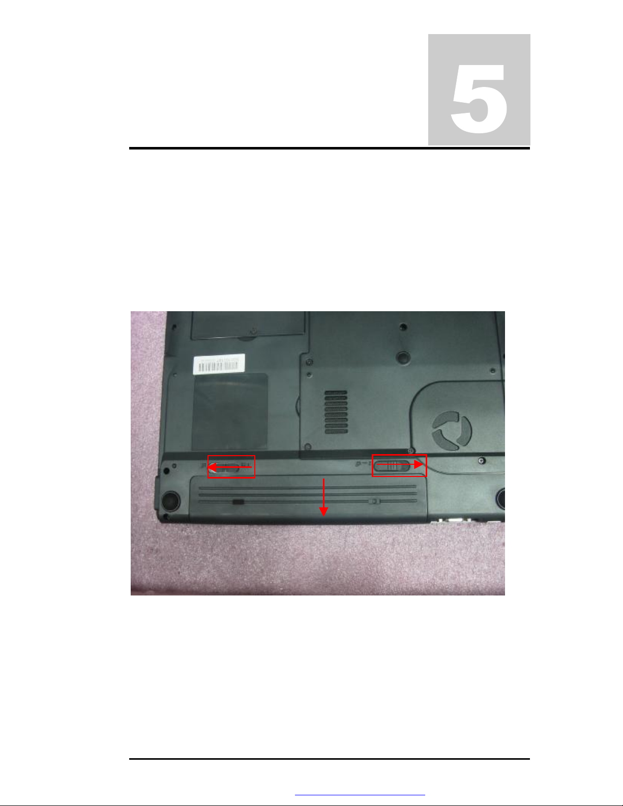
5.1.1 Removing the Battery Pack
The procedure for removing and replacing the battery pack is as follows:
To remove the battery pack, first slide the left latch to left; slide the right latch to right side
and hold it, then take out the battery pack with your finger.
Figure 5-1 Remove the battery pack
5.1.2 Removing the Internal Hard Disk Drive
The notebook provides a built-in hard disk for the primary IDE controller. The HDD is an
industry standard 2.5” IDE disk drive with a maximum height of 9.5mm.
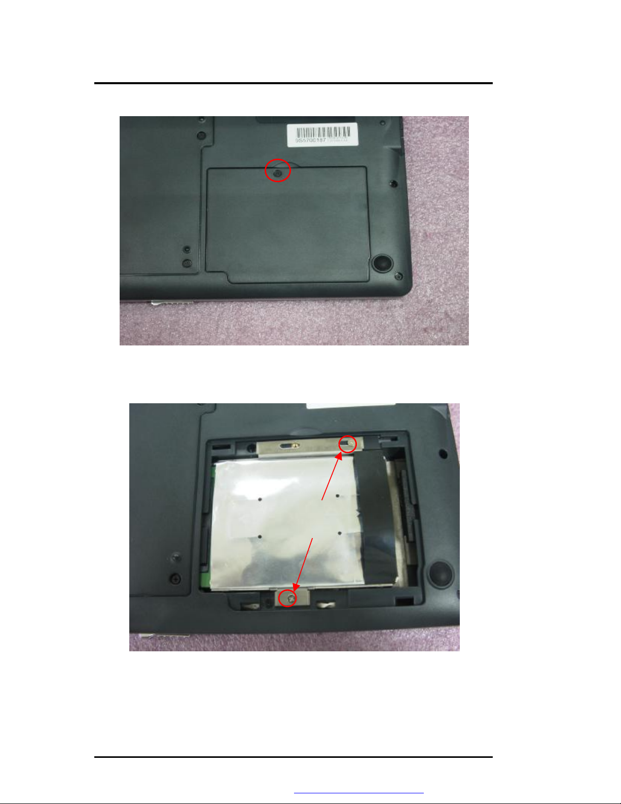
1. Find out the built-in hard disk secured with one screw at the upper of the bottom case.
Remove this screw and take out the hard disk door.
FSC V2030 Service Manual 5-1
PDF created with FinePrint pdfFactory trial version http://www.fineprint.com
Page 2
Maintenance & Disassembly
One Screw
Figure 5-2 Remove one screw
2. Remove two screws as picture
Two Screw
Figure 5-3 Remove two screws
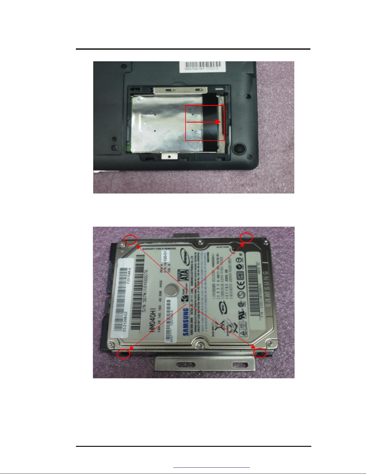
3. Pull the hard disk module from the connector as below picture shown.
5-2 FSC V2030 Service Manual
PDF created with FinePrint pdfFactory trial version http://www.fineprint.com
Page 3
Four Screws
Maintenance & Disassembly
Figure 5-4 Remove HDD
4. Remove four screws of frame HDD bracket plate.
Figure 5-5 Screws Locations of the frame HDD bracket plate
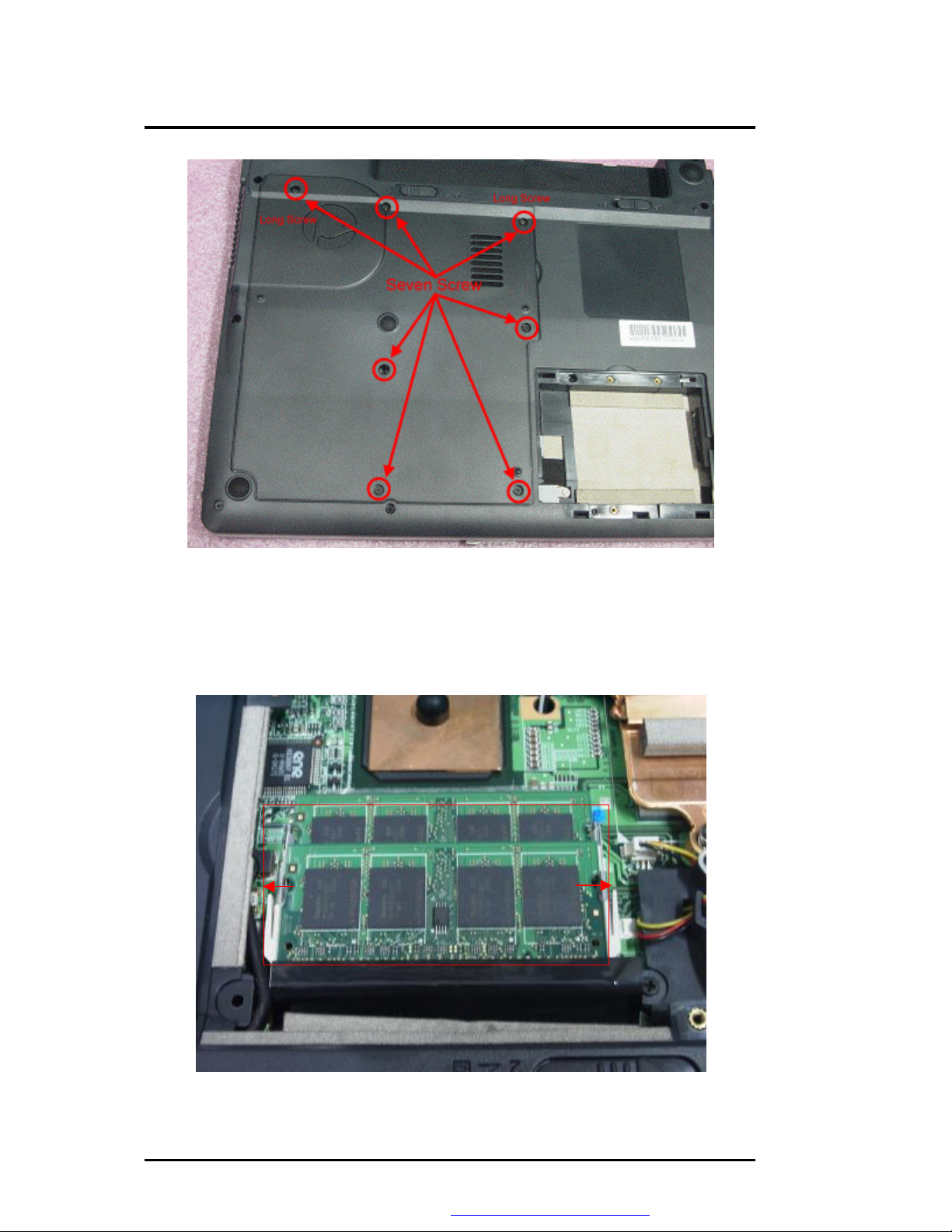
5.1.3 Removing the heat sink plate
The procedure for removing the heat sink plate is as follows:
1. Removing the plate, there are seven screws as the picture shown.
FSC V2030 Service Manual 5-3
PDF created with FinePrint pdfFactory trial version http://www.fineprint.com
Page 4
Maintenance & Disassembly
Figure 5-6 Remove seven screws
5.1.4 Removing RAM Module
The procedure for removing RAM Module is as follow:
You can see two RAM Sockets; you can upgrade your memory size to Maximum 2GB.
Figure 5-7 Remove RAM Module
5-4 FSC V2030 Service Manual
PDF created with FinePrint pdfFactory trial version http://www.fineprint.com
Page 5
Black connect MAIN
Maintenance & Disassembly
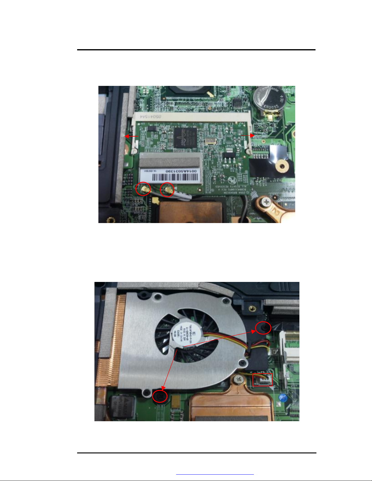
5.1.5 Removing the wireless LAN module
To remove the wireless LAN module, please remove wireless LAN antenna as below picture
shown.
White connect AUX
Figure 5-8 Removing the wireless LAN module
5.1.6 Removing the CPU FAN and Heat Sink
The procedure for removing the heat sink is as follows:
1. Remove the CPU FAN; there are two screws and one cable as below picture shown.
Two Screws
Figure 5-9 Removing the CPU FAN
FSC V2030 Service Manual 5-5
PDF created with FinePrint pdfFactory trial version http://www.fineprint.com
CPU FAN Cable
Page 6
Maintenance & Disassembly
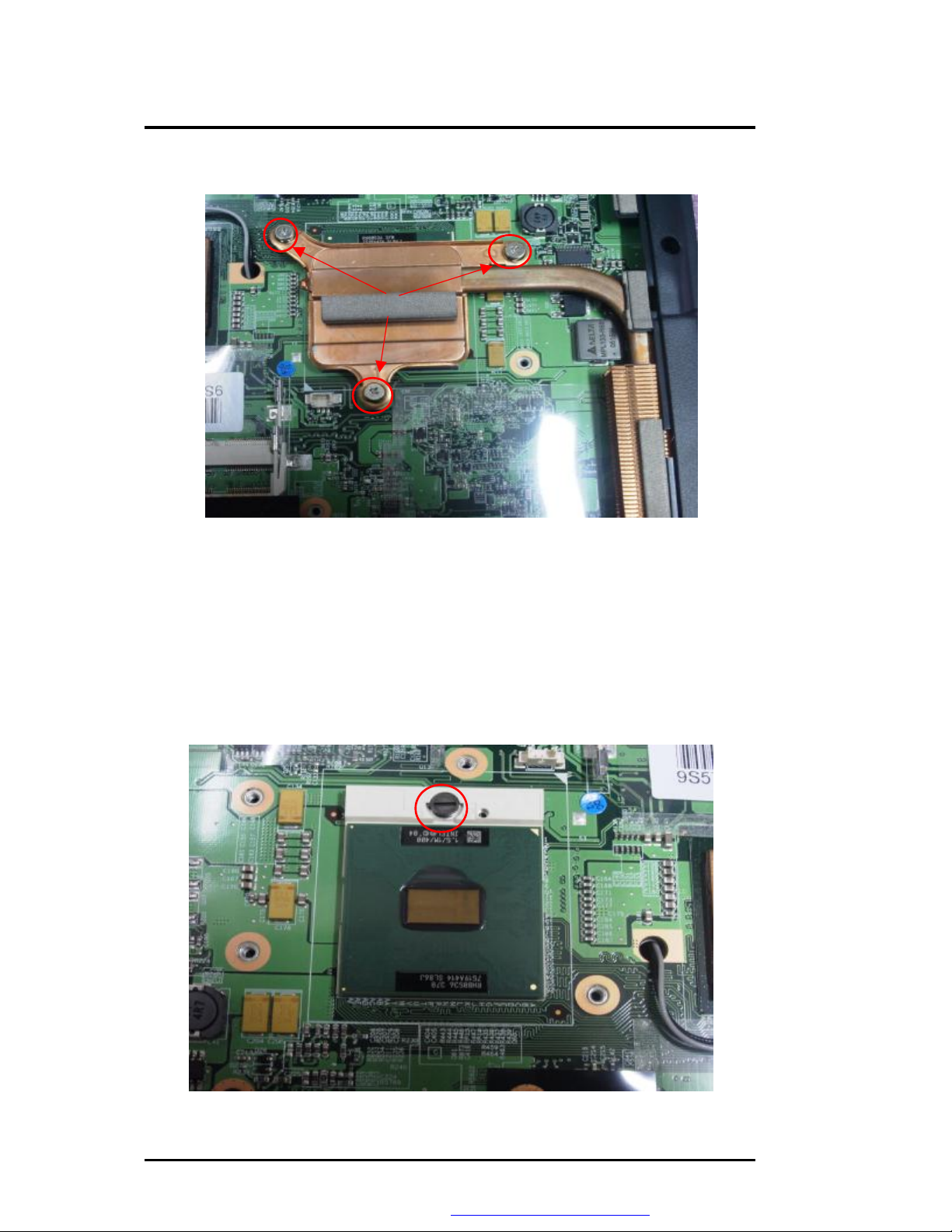
2. Remove the Heat Sink; There are three screws as below picture shown
Three Screws
Figure 5-10 Removing the Heat Sink Module
5.1.7 Removing the Intel CPU
The FSC V2030 features Intel Dothan Celeron processor. It is located on the bottom the
system motherboard.
To install or replace the CPU, follow the steps below:
1. Before removing the CPU module, you need first to disassemble heat sink plate and heat
sink and CPU FAN.
2.
Using a flat screwdriver, turn the socket lock counter-clockwise direction to unlock CPU
from the socket.
CPU Latch
Figure 5-11 CPU Assembly
5-6 FSC V2030 Service Manual
PDF created with FinePrint pdfFactory trial version http://www.fineprint.com
Page 7

Maintenance & Disassembly
5.1.8 Removing the Keyboard
The internal keyboard is located above the system top unit, Follow the steps below on how to
remove the keyboard:
1. Turn off the system and remove both AC adapter and the battery pack from the notebook
unit.
2.
Remove keyboard cover by gently pulling up with your finger as below
Figure 5-12 Remove keyboard Cover
3.
Lift the keyboard and tilt it towards the Plastic-M as below picture.
4.
Release keyboard cable by sliding the ZIF connector towards up direction.
Keyboard FPC Connector
Figure 5-13 Remove keyboard
FSC V2030 Service Manual 5-7
PDF created with FinePrint pdfFactory trial version http://www.fineprint.com
Page 8

Maintenance & Disassembly
5.1.9 Removing the LCD Panel
The procedure for removing the LCD Panel is as follows:
1.
Remove the four screws of rear side for the system unit.
Four Screws
Figure 5-14 Remove Four Screws
2. Removing LCD Cable and one screw as below picture shown.
One Screw
LCD Cable
LCD Cable
Figure 5-15 Remove LCD Module
3. Slowly pullout the LCD panel from the system unit.
5-8 FSC V2030 Service Manual
PDF created with FinePrint pdfFactory trial version http://www.fineprint.com
Page 9

Maintenance & Disassembly
5.1.10 Open the LCD module and swap the LCD panel
1.
Removing LCD BEZEL, There are six screws as below picture shown.
Six screws
Figure 5-16 Remove LCD BEZEL
Please remove LCD Bezel carefully by tools or hands. Serious move will cause LCD Bezel
broken damages.
2.
Removing LCD Panel, Remove three screws as below picture shown
FSC V2030 Service Manual 5-9
PDF created with FinePrint pdfFactory trial version http://www.fineprint.com
Page 10

Maintenance & Disassembly
Three Screws
Figure 5-17 Remove LCD Panel
3.
Removing INVT, There are two cable as below picture shown
Two Cable
Figure 5-18 Remove INVT
4. Removing LCD Cable as below picture shown.
5-10 FSC V2030 Service Manual
PDF created with FinePrint pdfFactory trial version http://www.fineprint.com
Page 11

Maintenance & Disassembly
One Cable
Figure 5-19 Remove LCD Cable
5.
Removing LCD HINGE Left, There are four screws as below picture shown
Four Screws
Figure 5-20 Remove LCD HINGE Left
6. Removing LCD HINGE Right, There are four screws as below picture shown
FSC V2030 Service Manual 5-11
PDF created with FinePrint pdfFactory trial version http://www.fineprint.com
Page 12

Maintenance & Disassembly
Four Screws
Figure 5-21 Remove LCD HINGE Right
7. After that we can swap the LCD panel
Please note not to scratch LCD penal while disassemble.
5.1.11 Removing DVD-ROM/RW Module
1. There is one screw on the bottom case, remove one screw. Then use flat screwdriver
push the DVD-ROM/RW Module.
One Screw
Figure 5-22 Remove DVD-ROM/RW Module
5-12 FSC V2030 Service Manual
PDF created with FinePrint pdfFactory trial version http://www.fineprint.com
Page 13

Maintenance & Disassembly
5.1.12 Removing the Top Cover
The procedure for removing the top cover is as follow:
Please see the location of top cover as the below picture shown.
1.
To remove the top cover, There are ten screws on the bottom case as below picture shown.
Ten Screws
Figure 5-23 Removing the ten screws of bottom case
2. You also need to remove the five screws and cables on the top cover as below picture
shown.
FSC V2030 Service Manual 5-13
PDF created with FinePrint pdfFactory trial version http://www.fineprint.com
Page 14

Five Screws
Maintenance & Disassembly
SW/B FPC
Cover switch cable
Modem cable
G/P FPC
Figure 5-24 Removing five screws and cables on the top cover
Modem cable
Speaker cable
Figure 5-25 Removing modem cable
5-14 FSC V2030 Service Manual
PDF created with FinePrint pdfFactory trial version http://www.fineprint.com
Page 15

Maintenance & Disassembly
5.1.13 Removing Switch Board
1.
There are two screws for this Switch Board as the picture shown.
Two Screws
Figure 5-26 Removing Switch Board
5.1.14 Removing the USB board
The procedure for removing the USB board is as follows:
1. There are one screw, one USB FPC and one cable for this USB board as the picture
shown.
One Screw
One cable
USB FPC
Figure 5-27 Removing the USB board
FSC V2030 Service Manual 5-15
PDF created with FinePrint pdfFactory trial version http://www.fineprint.com
Page 16

Maintenance & Disassembly
5.1.15 Removing the MDC Modem board
The procedure for removing the MDC Modem board is as follows:
1.
There are two screws and one cable for this MDC Modem board.
One cable
Figure 5-28 Removing Modem
Two Screw
5.1.16 Removing / Replacing the Motherboard
The motherboard contains the major chipset and components needed to run the FSC V2030
notebook. Follow the steps below on how to remove and replace the motherboard:
1.
Before removing the motherboard, you need first to disassemble the all basis unit modules
mentioned in the previous sections.
2. First remove four screws and two cable and two hex-bolts on the MotherBoard as below
picture shown.
5-16 FSC V2030 Service Manual
PDF created with FinePrint pdfFactory trial version http://www.fineprint.com
Page 17

Three
Screws
Maintenance & Disassembly
Two cable
Figure 5-29 Removing five screws
Two Hex-bolts
Figure 5-30 Removing two hex-bolts
3.
When remove all screws, slowly detached the main board from the base unit casing.
Notice the close gap between the volume control knob and button case and may use the
specific tooling to separate them more easily.
FSC V2030 Service Manual 5-17
PDF created with FinePrint pdfFactory trial version http://www.fineprint.com
Page 18

Maintenance & Disassembly
Figure 5-31 Front of M/B
Figure 5-32 back of M/B
5-18 FSC V2030 Service Manual
PDF created with FinePrint pdfFactory trial version http://www.fineprint.com
 Loading...