

Page 1

answers
Mainboard D1555
Deutsch / English / Français
2
Technisches Handbuch / Technical Manual
Page 2

Sie haben ...
... technische Fragen oder Probleme?
Wenden Sie sich bitte an:
• Ihren zuständigen Vertriebs part ner
• Ihre Verkaufsst elle
Aktuelle Informationen und Updates (z. B. BIOS-Update) zu unseren Mainboards finden Sie i m
Internet: http://www.fujitsu-siemens.com/mainboards
Are there ...
... any technical problems or other questions you need clarified?
Please contact:
• your sales partner
• your sales outlet
The latest information and updates (e.g. BIOS update) on our mainboards can be found on the
Internet under: http://www.fujitsu-siemens.com/mainboards
Vous avez ...
...des questions t echniques ou des problèmes ?
Veuillez contacter :
• Votre partenaire Commercial
• Votre point de Vente
Les dernières informations ai nsi que les updates (p.ex. B I OS-Update) par rapport à nos cartes
mères sont à votre disposition sur Internet : ht tp://www.fujitsu-siemens.com/mainboards
Page 3

Page 4

Dieses Handbuch wurde auf Recycling-Papier gedruckt.
This manual has been printed on recycled paper.
Ce manuel est imprimé sur du papier recyclé.
Este manual ha sido impreso sobre papel reciclado.
Questo manuale è stato stampato su carta da riciclaggio.
Denna handbok är tryckt på recyclingpapper.
Dit handboek werd op recycling-papier gedrukt.
Herausgegeben von/Published by
Fujitsu Siemens Computers GmbH
Bestell-Nr./Order No.:
Printed in the Federal Republic of Germany
AG 0303 03/03
A26361-D1555-Z121-1-6319
A26361-D1555-Z121-1-6319
Page 5

Deutsch
English
Mainboard D1555
Technisches Handbuch
Technical Manual
Français
Ausgabe März 2003
March 2003 edition
Page 6

Intel, Pentium und Celeron s i nd ei nget ragene Warenzeichen der Intel Corporation, USA.
Microsoft, MS, MS-DOS und Windows sind eingetragene Warenzeichen der Microsoft
Corporation.
PS/2 und OS/2 Warp sind eingetragene Warenz ei chen von International Business Machines,
Inc.
Alle weiteren genannten Warenzeichen s i nd Warenzeichen oder eingetragene Warenzeichen
der jeweiligen Inhaber und werden als geschüt zt anerkannt.
Copyright Fujitsu Si em ens Computers GmbH 2003
Alle Rechte vorbehalten, i nsbesondere (auch auszugsweise) di e der Übersetzung, des
Nachdrucks, der Wiedergabe durch Kopieren oder ähnliche Verfahren.
Zuwiderhandlungen verpflichten zu S chadenersatz.
Alle Rechte vorbehalten, insbesondere für den Fall der Patenterteil ung oder GM -Eintragung.
Liefermöglichkeiten und technische Änderungen vorbehalten.
Dieses Handbuch wurde erstellt von
cognitas. Gesellschaft für Technik-Dokument at i on mbH
www.cognitas.de
Intel, Pentium and Celeron are registered trademarks of Intel Corporation, USA.
Microsoft, MS, MS-DOS and Windows are registered trademarks of Microsoft Corporation.
PS/2 and OS/2 Warp are registered tradem arks of International Busi ness Machines, Inc.
All other trademarks referenced are trademarks or registered tradem arks of their respectiv e
owners, whose protected rights are acknowledged.
All rights, includi ng ri ghts of translation, reproduc t i on by printing, copying or similar methods,
even of parts are reserved.
Offenders will be liable for damages.
All rights, including rights creat ed by patent grant or registration of a utilit y model or design,
are reserved. Delivery subject to availability.
Right of technical modi f i cation reserved.
This manual was produced by
cognitas. Gesellschaft für Technik-Dokument at i on mbH
www.cognitas.de
Page 7

Page 8
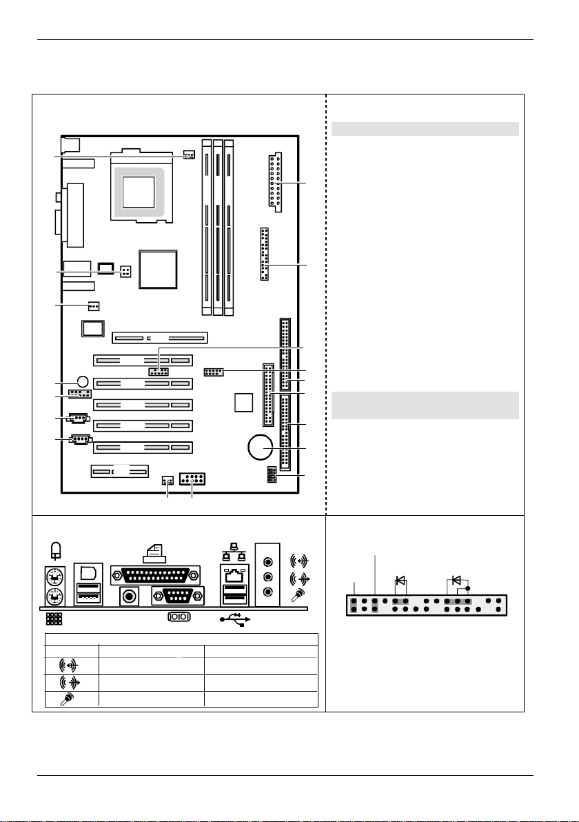
Übersicht/Overview Mainboard D1555
Interne Anschlüsse und Steckplätze / Internal
connectors and slots
18
DIMM 2
DIMM 1
CPU
Pent ium 4
DIMM 3
17
16
AGP
PCI 1
15
14
13
12
PCI 2
PCI 3
PCI 4
PCI 5
CNR
1 = Stromversorgung / Power supply
2 = Bedienfeld / Front panel
3 = USB C/D
4 = USB E/F
5 = Diskettenlaufwerk / Floppy disk drive
6 = IDE-Laufwerke 3/4 / IDE-drives 3/4
1
7 = IDE-Laufwerke 1/2 / IDE-drives 1/2
8 = Batterie / Battery
9 = Schalter / Switch
10 = FireWire-Anschluss (1394) / FireWire
connector (1394)
11 = Lüfter 2 / Fan 2
2
12 = AUX-Audio in
13 = CD-Audio in
14 = Audio-Bedienfeld / Audio front panel
15 = Summer / Buzzer
16 = S/PDIF-Anschluss / S/PDIF
3
4
5
6
connector
17 = Prozessor-Stromversorgung /
Processor power supply
18 = Lüfter 1 / Fan 1
Optionale Komponenten / Optional
components
7
8
9
11
10
Externe Anschlüsse / External connectors
1394
Umschaltbar durch Treiber /
Standard 6-channel
Line In (blau/blue)
Line Out (grün/green)
Mic In (rot/red)
Switchable via driver
Rear
Front
Center / Low
Bedienfeld / Front panel
Power On/Off
HD-LED
1)
Reset
1) Cable is not included in the delivery scope.
2) 2-pin or 3-pin conne ctor possible
1)
Power On
1) 2)
LED
1
2
Umschlag /Cpover
Page 9

Inhalt
Übersicht/Overview Mainboard D1555
Mainboard D1555.............................................................................................................................1
Darstellungsmittel......................................................................................................................1
Wichtige Hinweise.............................................................................................................................2
Hinweise zu Baugruppen...........................................................................................................2
Übersicht Leistungsmerkmale............................................................................................................3
Besondere Merkmale.................................................................................................................4
Kurzanleitung Mainboard einbauen....................................................................................................5
Vor dem Einbau.........................................................................................................................5
Anschlüsse und Steckverbinder ....................................................................................................7
Externe Anschlüsse...........................................................................................................................7
LAN-Anschluss..........................................................................................................................7
2-, 4- oder 6-Kanal-Audiobetrieb................................................................................................7
Interne Anschlüsse und S t e ckverbinder.............................................................................................9
Festplatten-Anschluss ...............................................................................................................9
Pinbelegung interne Anschlüsse........................................................................................................9
Einstellungen mit Schaltern und Steckbrücken..........................................................................14
Erweiterungen / Hochrüsten.........................................................................................................15
Prozessor tauschen.........................................................................................................................15
Prozessor ausbauen/einbauen ................................................................................................15
Hauptspeicher hochrüsten...............................................................................................................17
AGP-Grafikkarten hochrüsten..........................................................................................................18
PCI-Karten hochrüsten....................................................................................................................18
PCI-Bus-Interrupts - Auswahl des richtigen PCI-Steckplatzes.................................................18
Lithium-Batterie austauschen.................................................................................................. 20
BIOS-Update...................................................................................................................................21
BIOS-Recovery - System-BIOS wiederherstellen ............................................................................21
Microcode-Update ...........................................................................................................................22
Treiber.............................................................................................................................................23
Anhang...........................................................................................................................................24
Elektrische Eigenschaften ...............................................................................................................24
APM und ACPI Systemstatus, Stromsparmodi................................................................................25
Mainboard-Revision und BIOS-Version ...........................................................................................26
Fehlermeldungen...........................................................................................................................27
Glossar............................................................................................................................................31
A26361-D1555-Z121-2-6319
Page 10

Page 11

Mainboard D1555
Ihr Mainboard ist in verschiedenen Ausbaustufen erhältli ch. Abhängig von der Konfiguration I hres
Mainboards kann es vorkomm en, dass Sie einige Hardware-Komponenten nic ht vorfinden, obwohl
diese in diesem Handbuch beschri eben sind.
Weitere Informationen
Informationen zum BIOS-Setup und zusätzliche Beschreibungen zu den Trei bern finden Sie:
• in den Readme-Dateien auf Ihrer Festplat t e
• auf beiliegenden Treiber-Disketten
• auf der CD "Drivers & Utilities Collection" oder "Drivers & Utilities" oder "ServerStart".
Um die Dokumentation aufrufen z u können, muss das Programm Acrobat Reader installiert
sein. Sie finden das Program m i m CD-ROM -Verzeichnis: utls /acrobat.
i
Weitere Informationen finden Si e i n den entsprechenden readme.txt-Datei en.
Darstellungsmittel
In diesem Handbuch werden folgende Darstel lungsmittel verwendet.
kennzeichnet Hinweise, deren Ni chtbeachtung Ihre Gesundheit gefährdet oder zu
Sachschäden führt.
!
kennzeichnet zusätzliche Informationen und Tipps f ür den sachgerechten Umgang mit
dem System.
i
Ê kennzeichnet einen Arbeitsschritt, den Sie ausführen müssen.
Ë bedeutet, dass Sie an di eser Stelle ein Leerzeichen eingeben müssen.
Ú bedeutet, dass Sie nach dem ei ngegebenen Text die Eingabetaste drück en m üssen.
Texte in Schreibmaschinenschrift stellen Bildschirm ausgaben dar.
Texte in fetter Schreibmaschinenschrift sind Texte, die Sie über die Tastatur eingeben
müssen.
Kursive Schrift kennzeichnet Befehle oder Menüpunkte.
"Anführungszeichen" k ennzeichnen Kapitelnamen und Begriff e, die hervorgehoben werden sollen.
A26361-D1555-Z121-2-6319 Deutsch - 1
Page 12
Wichtige Hinweise
Wichtige Hinweise
Bei eingebautem Mainboard müssen S i e das System öffnen, um Zugri ff auf das Mainboard zu
bekommen. Wie Sie das Sy stem zerlegen und wieder zusammenbauen, i st in der Betriebsanleitung
des Systems beschrieben.
Verbindungskabel zu Peripheriegerät en m üssen über eine ausreichende Abschi rm ung verfügen.
Beachten Sie die Sicherheitshinweise in der Betriebsanleitung des Systems.
!
Bei unsachgemäßem Austausch der Lithium-Batterie bes t eht Explosionsgefahr.
Beachten Sie deshalb unbedingt die Angaben im Kapitel "Erweiterungen / Hochrüsten" "Lithium-Batterie austauschen".
Während des Betriebs können Bauteil e sehr heiß werden. Beachten Sie dies, wenn S i e
Erweiterungen auf dem Mainboard vornehmen wollen. Es besteht Verbrennungsgefahr!
Diese Baugruppe erfüllt in der ausgeli eferten Ausführung die Anforderungen der EGRichtlinie 89/336/EWG "E l ektromagnetische Verträgl i chkeit".
Die Konformität wurde in einer typischen Konfiguration eines Personal Computers
geprüft.
Beim Einbau der Baugruppe sind die spez ifischen Einbauhinweise gemäß der
Anleitung des jeweiligen Endgerätes zu beachten.
Die Gewährleistung erlischt , wenn Sie durch Einbau oder Austausc h von Erweiterungen
Defekte am System verursachen. Informationen darüber, wel che Erweiterungen Sie
i
verwenden können, erhalten Sie bei Ihrer V erkaufsstelle oder unserem S ervice.
Hinweise zu Baugruppen
Um Schäden des Mainboards, der darauf befindlichen Bauteile und Leiterbahnen z u vermeiden,
bauen Sie Baugruppen mit größter Sorgfalt und Vorsicht ein und aus. Ac ht en Sie darauf,
Baugruppen gerade einzusetzen, ohne Baut ei l e, Leiterbahnen oder andere Komponenten (z. B.
EMI-Federkontakte) zu bes chädigen.
Ziehen Sie den Netzstecker aus der Schutzkontakt -S teckdose, damit Sy stem und Mainboard von
der Netzspannung getrennt sind.
Gehen Sie sorgfältig mit den V erri egel ungsmechanismen (Rastnasen und Zent ri erbol zen etc.) um,
wenn Sie das Mainboard oder Komponenten (z. B . Speichermodule oder Prozessor) austauschen.
Verwenden Sie niemals scharf e Gegenstände (Schraubendreher) als Hebelwerkzeuge.
Baugruppen mit elektrostat i sch gefährdeten Bauelementen (EGB) können durch
den abgebildeten Aufkleber gekennzei chnet sein:
Wenn Sie Baugruppen mit EGB handhaben, beac ht en Sie unbedingt folgendes:
• Sie müssen sic h statisch entladen (z. B. durch Berühren eines geerdeten
Gegenstandes), bevor Sie mit Baugruppen arbeiten.
• Verwendete Geräte und Werkzeuge müs sen frei von statisc her Aufladung sein.
• Ziehen Sie den Netzstec ker, bevor Sie Baugruppen stecken oder ziehen.
• Fassen Sie die Baugruppen nur am Rand an.
• Berühren Sie keine Ansc hl uss-Stifte oder Leiterbahnen auf der Baugruppe.
2 - Deutsch A26361-D1555-Z121-2-6319
Page 13
Übersicht Leistungsmerkmale
Übersicht Leistungsmerkmale
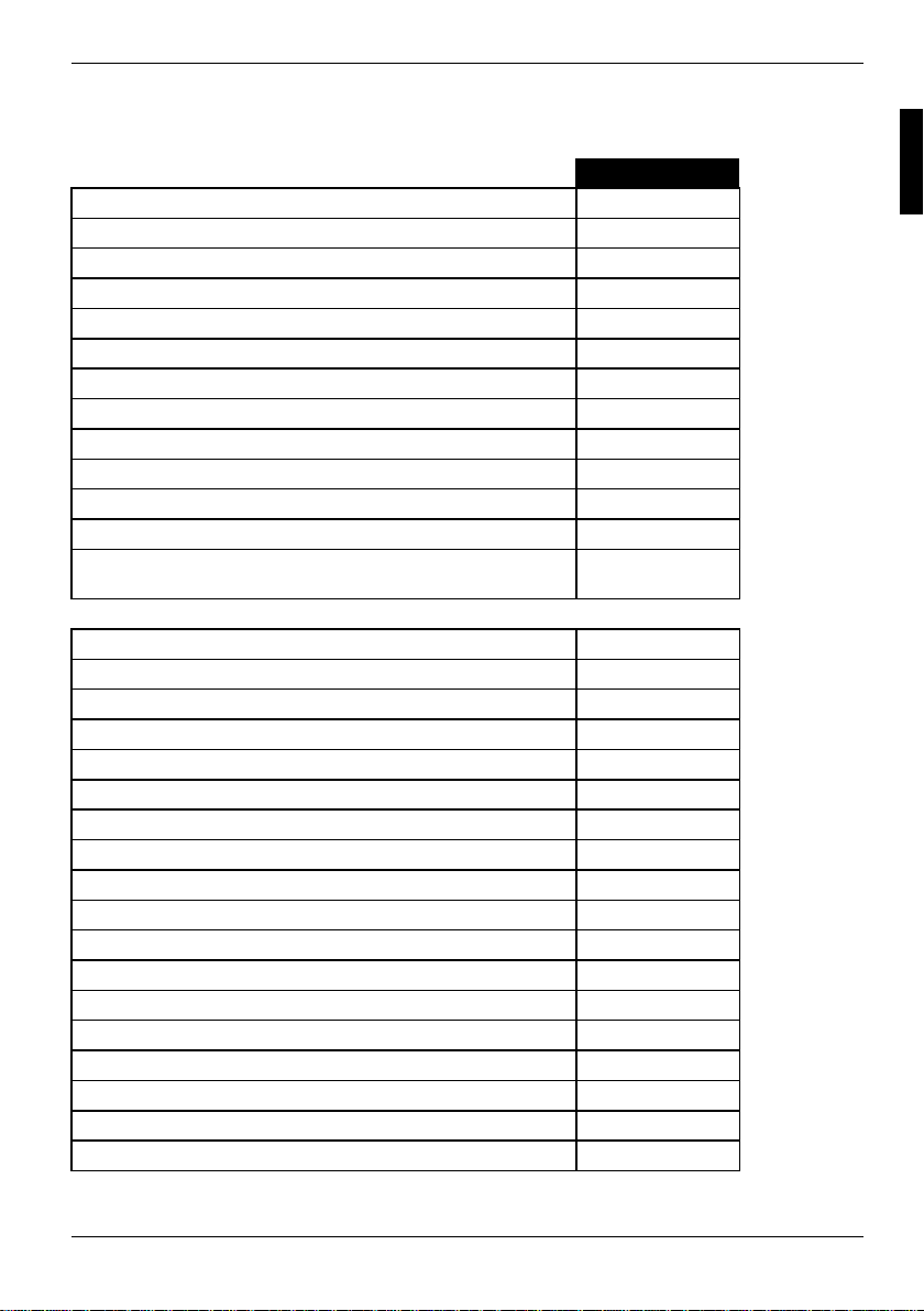
Onboard Merkmale D1555-C
Chipsatz SiS 648 / 963
Format ATX
VGA Audio / 6-Kanal / S/PDIF 5.1 ! / ! / !
Summer / int. Lautsprecheranschluss ! / -
LAN / mit Alert-on-LAN ! / -
RAID FireWire
HI-SPEED USB 2.0 !
SmartCard Leseranschluss (USB / seriell) - / Temperaturüberwachung Systemüberwachung Unterstützung für Fujitsu Siemens Computers Tast at ur mit
Einschalttaste
Interne Anschlüsse
DIMM Steckplätze (DDR 333 SDRAM / DDR 266 SDRAM) 2 / 3
AGP-Steckplatz (4/8x, 32 Bit, 66 MHz, 1,5 V) 1
PCI-Steckplatz (32 Bit, 33 MHz, 5 V und 3,3 V) 5
CNR-Steckplatz (Ty pe A, AC‘97 only) 1
IDE RAID Schnittstelle (RAID 1,2 / IDE 3,4) IDE-Schnittst el l e (Ul tra DMA/133) 2
Diskettenlaufwerksschnittstelle (bis zu 2,88 Mbyte) 1
S/PDIF* (digital Audio) CD / AUX Audio Input 1 / 1
Bedienfeld Audio (Kopfhörer, Mi krofon) 1
Wake-on-LAN IEEE 1394 Stecker* (FireWireTM)1
USB-Anschlüsse* (2.0, ~480 MB/s) 2 oder 4
Serielle Anschlüsse* (FIF O, 16550 compatible) Lüfteranschlüsse PSU** / CPU / AUX1 / AUX2 - / 1 / 1 / SMBus Anschluss* (Gehäuse Temperatur) Gehäuseüberwachung* (Gehäuse offen) Stromversorgung ATX / A T X12V / AGP PRO 1 / 1 / -
TM
!
-
A26361-D1555-Z121-2-6319 Deutsch - 3
Page 14
Übersicht Leistungsmerkmale
Externe Anschlüsse
VGA Audio Mic In / Line in / Li ne out
oder Rear / Front / Center, Low (über Treiber)
Game/MIDI S/PDIF 5.1 (Cinch) 1
LAN (RJ-45) 1
PS/2 Maus/Tastatur 1 / 1
1394-Anschluss (FireWire) 1
USB-Anschlüsse (2. 0, ~480 MB/s) 4
Serielle Anschlüsse (FI F O, 16550 compatible) 1
Paralleler Anschluss (EPP/ECP) 1
* wird für interne Geräte verwendet oder optional über Bedienfeld vorne/hinten
** wird nicht von Standard-Stromversorgungen unterstützt
1 / 1 / 1
Besondere Merkmale
Ihr Mainboard ist in verschiedenen Ausbaustufen erhältli ch. Abhängig von der Konfiguration I hres
Mainboards besitzt oder unterstützt das Mainboard die nac hfolgend beschriebenen Merkmale.
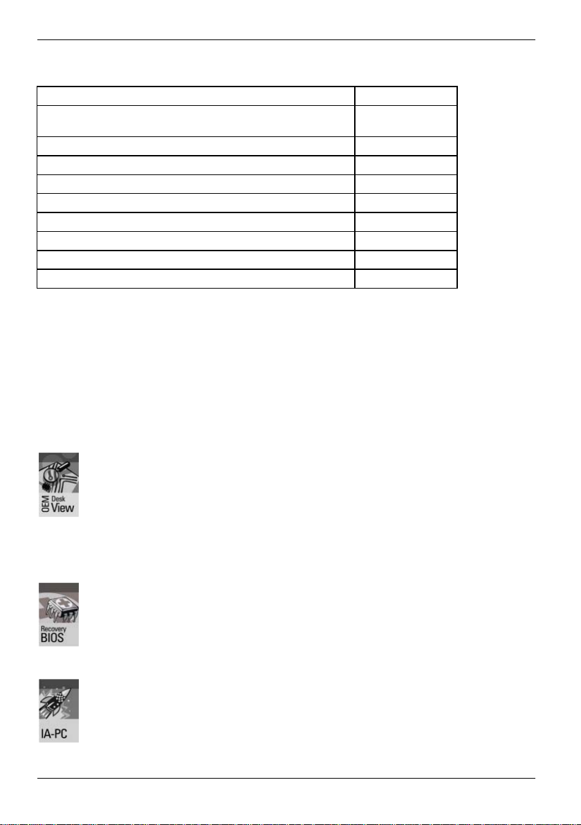
DeskView / DeskViewOEM
Die netzwerkfähige Manageability Software DeskView/DeskViewOEM* besteht im
Wesentlichen aus drei Modulen:
• DeskInfo zeigt die wi chtigen Gerätedaten der PC in einem Netz werk an (lokal
und/oder auf einem Administrator-PC).
• DeskAlert überwacht abhängig v on der M ai nboard-Variante die
Funktionsfähigkeit al l er wesentlichen Komponenten und löst gegebenenfalls
Alarme aus.
• DeskFlash führt einen B I OS-Update unter Microsoft Windows durch.
Recovery-BIOS
Wenn während eines BIOS-Updates ein Fehler auf t ri tt (z. B. durch Strom ausfall), ist
das System-BIOS zerstört. Alle Fujit su Siemens Computers Mainboards verfügen
über ein Recovery-BIOS. Dam i t kann ein zerstörtes BIOS einfach wiederhergestellt
werden. Eine genaue Anleitung finden Si e i m Kapitel "BIOS-Recovery - System-BIOS
wiederherstellen".
IA-PC
Instantly Available PC gewährleistet eine schnelle Verfügbarkeit des PC aus einem
Energiesparmodus. Der PC befindet sich ohne zeitaufwändiges S t arten innerhalb
weniger Sekunden wieder exakt in dem Zus tand, in dem er sich befand, als er
abgeschaltet wurde. Abhängig vo m B etriebssystem lässt sich der PC bei geöffneten
Anwendungen einfach durch Drücken des Ein-/Ausschalters i n ei nen
Energiesparmodus schalten.
4 - Deutsch A26361-D1555-Z121-2-6319
Page 15
Kurzanleitung Mainboard einbauen
Wenn Sie das Mainboard einzeln gekauft haben, können Sie das Mainboard nach der fol genden
Kurzanleitung in Ihr Sys tem einbauen.
Die hier beschriebenen Tätigkeiten setzen Grundwissen über PC voraus und können nicht von
einem Laien ausgeübt werden. Falls Si e sich nicht sicher s i nd, ob Sie ausreichend Fachwissen
besitzen, so überlass en S i e di ese Arbeiten einem Fachmann.
Die Abbildungen der Systeme z ei gen B eispiele von möglichen Gehäusen.
Vor dem Einbau
Ê Beachten Sie die Sicherheitshinweise i m Kapitel "Wichtige Hinweis e".
Ê Prüfen Sie, ob Prozessor, Speichermodul e und S tromversorgung zu diesem Mainboard
passen:
− Prozessoren siehe Kapit el " P rozessor tauschen".
− Speichermodule siehe Kapitel " Hauptspeicher hochrüsten".
− Stromversorgung siehe Kapitel "Elektrische E i genschaften".
Ê Prüfen Sie, ob der Strombedarf der Lüfter (Prozessor, Gehäuse) nicht die Belas tbarkeit der
Lüfteranschlüsse übers chreitet (siehe Kapitel "Elektrische Eigens chaften").
Ê Bauen Sie zunächst nur die unbedingt benötigten Komponenten ein (Grafikkarte, Prozessor
und Kühlkörper, ein Speichermodul) und schließen Sie nur die benötigten Ans chlüsse an
(Netzteil, Gehäuseansc hl üsse wie ATX-Einschal ter, Festplatte oder Disk ettenlaufwerk). Erst
wenn diese Minimalkonfigurat i on erf olgreich hochfährt, sollten Sie weitere Karten und Geräte
einbauen (siehe Kapitel "Erweit erungen / Hochrüsten").
Einbau
Ê Bestücken Sie das Mainboard möglichs t schon vor dem Einbau in das Gehäuse mi t Prozessor,
Kühlkörper und Speichermodulen. Weitere Hinweise dazu finden Sie im K api tel "Prozessor
tauschen".
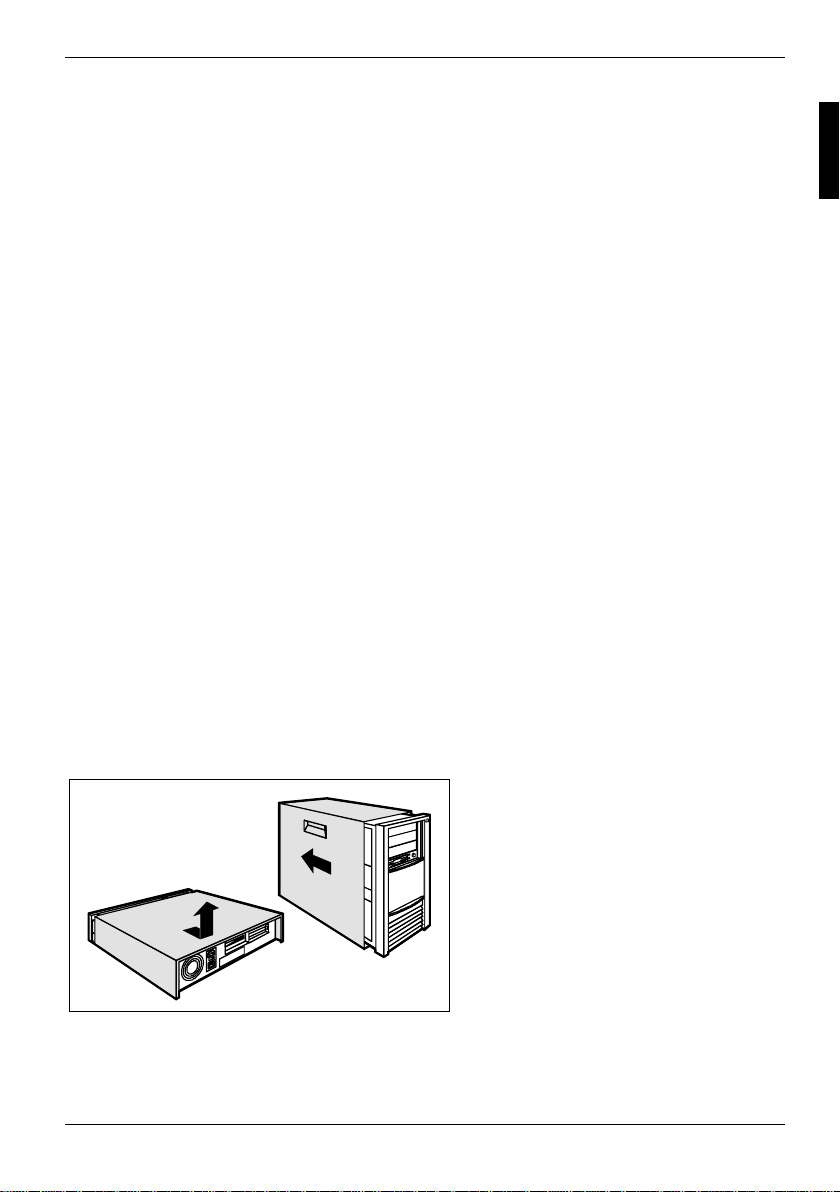
Ê Öffnen Sie das Gehäuse, so wie in der
Betriebsanleitung Ihres S ystems
beschrieben.
A26361-D1555-Z121-2-6319 Deutsch - 5
Page 16
Kurzanleitung Mainboard einbauen
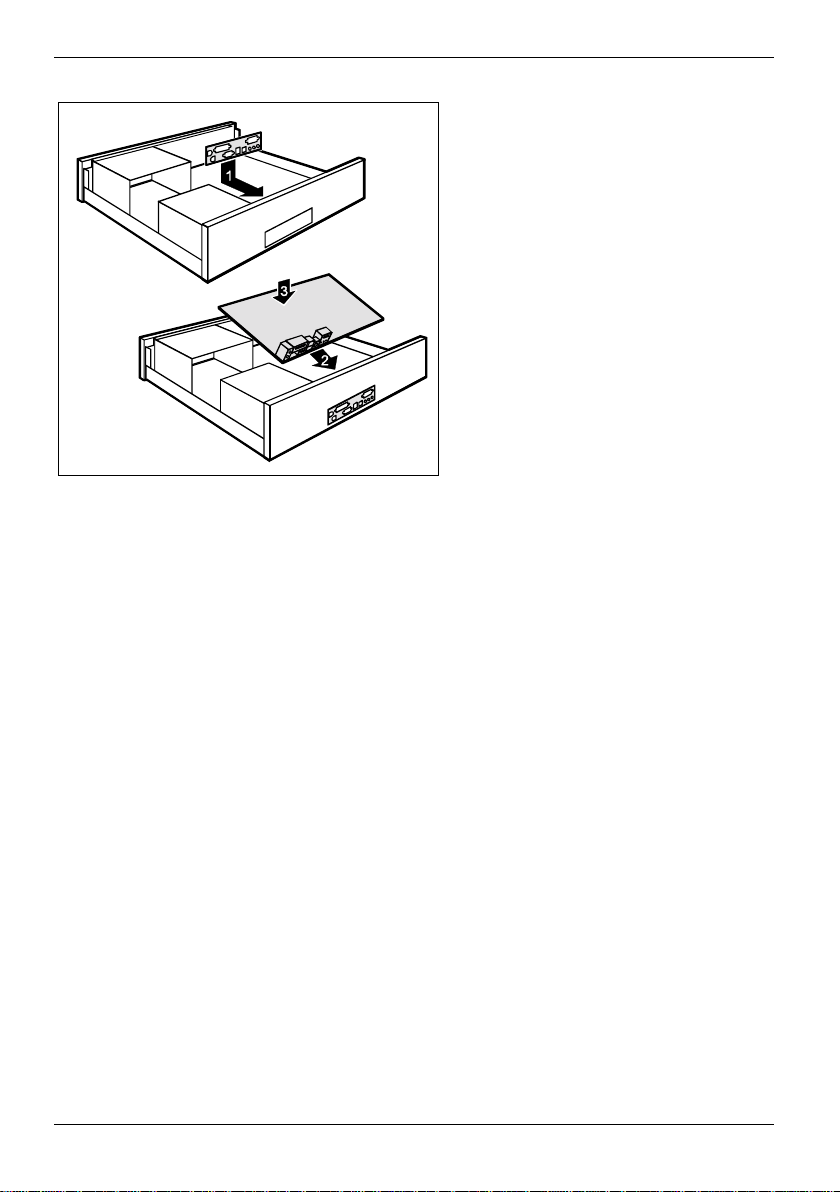
Ê Sollte im Gehäuse kein passendes
Anschlussfeld v orhanden sein, müssen
Sie das mitgelieferte A nschlussfeld (1)
einbauen.
Achten Sie auf die Ausrichtung der Blende,
damit die Anschlüss e dem Mainboard
hinterher passen.
Ê Setzen Sie das Mainboard an der Kante
an, an der sich das Anschl ussfeld
befindet (2), und setzen Sie di e
Baugruppe dann ins Gehäuse ein (3).
Achten Sie darauf, dass A bstandshalter im
Gehäuse nur an Stellen montiert sind, an
denen im Mainboard Befestigungsl öcher
sind.
Ê Befestigen Sie das Mainboard mit den
mitgelieferten Schrauben.
Ê Stecken Sie die Stecker für St rom versorgung, Bedienfeld und Laufwerke auf di e
entsprechenden Anschlüsse auf dem Mainboard.
Treiberinstallation
Ê Installieren Sie die Treiber für den Chipsatz. Sie finden die Treiber auf der beigelegten CD
"Drivers & Utilities". Wie Sie die Treiber inst allieren, finden Sie im Kapitel "Treiber".
6 - Deutsch A26361-D1555-Z121-2-6319
Page 17
Anschlüsse und Steckverbinder
Die Position der Anschl üsse und Steckverbinder finden Sie auf der Seite "Ums chlag/Cover".
Die markierten Komponenten und St eckverbinder müssen nic ht auf dem Mainboard vorhanden sein.
Externe Anschlüsse
Die Position der externen Anschlüsse finden Sie auf der Seite "Umschlag/Cover" .
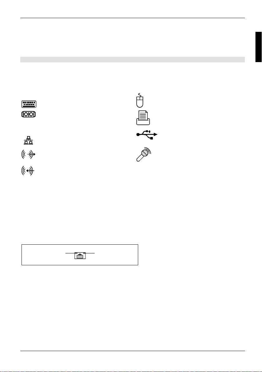
PS/2 Tastaturanschluss, violett PS/2-Mausanschlus s, grün
Serielle Schnittstelle, türkis
LAN
* Die Umschaltung auf 6-Kanal-Audi o erfolgt mit Hilfe eines Trei bers.
LAN-Anschluss USB - Universal Serial Bus, schwarz
Audioausgang (Line out), hellgrün
oder Front*
Audioeingang (Line in), hellblau
oder Center / Low*
1394
Parallele Schnittstelle/Drucker,
burgund
Mikrofonanschluss , rosa
oder Surround*
FireWire, grau
LAN-Anschluss
Das Mainboard ist mit dem ADMtek AN983B LAN-Controller bestückt. Dieser LAN-Controller
unterstützt die Übertragungsgeschwindigkeiten 10 Mbit /s und 100 Mbit/s. Der LAN-Cont rol l er verfügt
über einen 2 Kbyte großen Sende- und Empfangspuf fer (FIFO) und unterstützt die WOLFunktionalität durch Magic Packet.
Der LAN RJ45-Anschluss besitzt zwei LEDs (Leuchtdioden).
1 = Es besteht eine Verbindung (z. B. zu
2
1
einem Hub).
2 = Link Modus: die LAN-Verbindung ist aktiv.
WOL-Modus: ein Magic Pack et
empfangen.
TM
wird
2-, 4- oder 6-Kanal-Audiobetrieb
Das Mainboard unterstützt ei nen 6-Kanal-Audioausgang (2 Front-, 2 Rear-, 1 Center- und 1
Subwoofer-Kanal). Damit ist es möglich, 4 oder 6 Lautsprec her anzuschließen und somit einen
besseren Surround-Sound-Effekt zu erzielen.
Treiber
Für den 2-, 4- oder 6-Kanal-Audiobetrieb muss ein entsprec hender Treiber ins talliert sein. Falls der
Treiber noch nicht installiert ist, gehen S i e vor wie im Kapitel "Erweiterungen / Hochrüsten",
Abschnitt "Treiber" beschrieben.
A26361-D1555-Z121-2-6319 Deutsch - 7
Page 18
Externe Anschlüsse
Anschließen von Lautsprechern
Die Anzahl der angeschloss enen Laut sprecher sollte der Anzahl der Audiokanäle entsprechen, die
Sie in der Treiber-Software auswählen.
Externe Audioanschlüsse verwenden
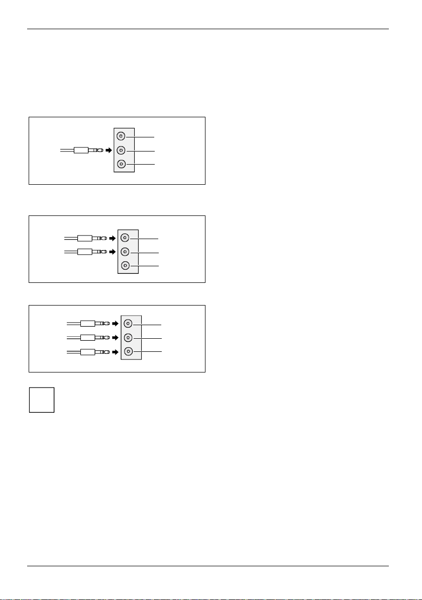
Analoger 2-Kanal-Audioausgang
1
2
3
1
2
3
1
2
3
Je nach Treiberversion und Betriebssystem können die Funktionen von dieser
Darstellung abweichen. Weitere Informationen fi nden S i e gegebenenf alls in der jeweiligen
i
Hilfe von Treiber und Software.
Bei der 2-Kanal-Konfiguration stehen die
Funktionen Line-Out, Line-In und MIC zur
Verfügung.
1 = Line-In (blau)
2 = Line-Out (Front-Kanäle, grün)
3 = MIC (rot)
Analoger 4-Kanal-Audioausgang
Line-In wird bei der 4-Kanal-Konfiguration in die
Funktion Rear-Out umgewandelt.
1 = Line-In (Rear-Kanäle. blau)
2 = Line-Out (Front-Kanäle, grün)
3 = MIC (rot)
Analoger 6-Kanal-Audioausgang
Line-In und MIC werden bei der 6-KanalKonfiguration in die Funktion Line-Out
umgewandelt.
1 = Line-In (Rear-Kanäle. blau)
2 = Line-Out (Front-Kanäle, grün)
3 = MIC (Center- und Subwoofer-Kanal, rot)
Einstellung für 2-, 4- oder 6-Kanal-Audiobetrieb aus wä hlen
Abhängig vom Treiber für den Audiobetrieb und vom verwendeten Betriebssystem können Sie die
Audioeigenschaften konfigurieren, z. B. unter Windows 2000 unter Start - Einstellungen -
Systemsteuerung - Sounds und Multimedia.
8 - Deutsch A26361-D1555-Z121-2-6319
Page 19
Interne Anschlüsse und Steckverbinder
Interne Anschlüsse und Steckverbinder
Die Position der internen Ans chlüsse und Steckverbinder finden Sie auf der Seite
"Umschlag/Cover". Zu eini gen Anschlüssen finden Sie hi er noch Zusatzinformationen.
Festplatten-Anschluss
Eine Ultra-ATA/66-, Ult ra-ATA/100 oder Ultra-ATA/133-Fes t pl atte muss mit einer s peziellen, für den
Ultra-ATA/66-, Ultra-AT A/100- bzw. Ultra-ATA/133-Betrieb ausgelegten Leitung angesc hl ossen
werden.
Ê Verbinden Sie das blau markierte Ende der Leitung mit dem M ai nboard.
Pinbelegung interne Anschlüsse
Im folgenden finden Sie die Pinbel egung ei ni ger i nterner Anschlüsse in Deutsch und/oder Englisch.
Einige der beschriebenen Anschl üsse können optional sein!
i
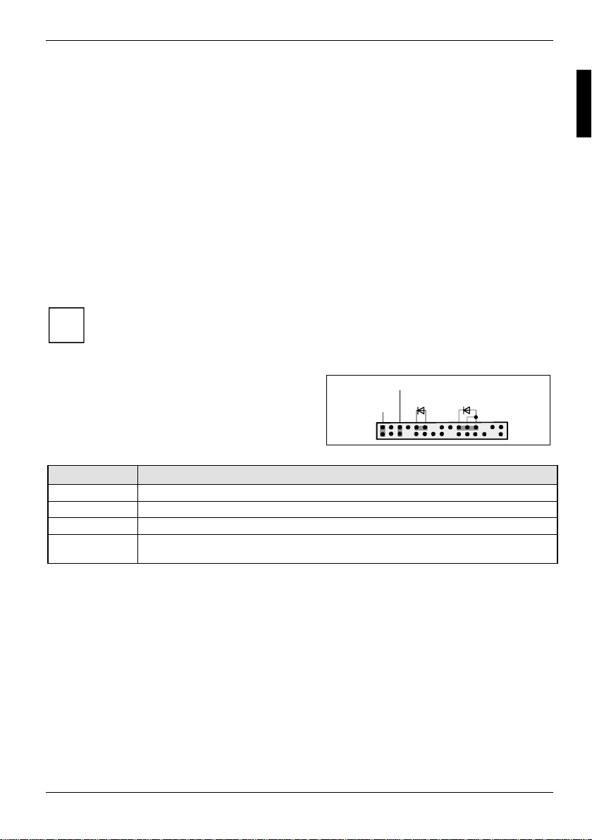
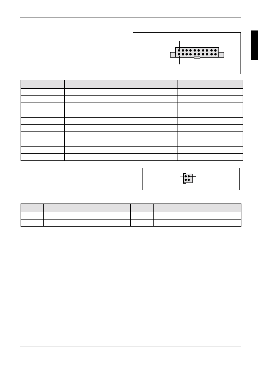
Bedienfeld / Front panel
Achten Sie bei den LEDs auf di e P ol ung. Oft ist bei
Power On/Off
1)
Reset
HD-LED
1)
Power On
1) 3)
LED
den Anschluss-Leitungen der P l uspol durch ein
farbiges Kabel gekennzeichnet.
Anschluss Anmerkung
Reset
Power On/Off
HD LED
Power On LED Zei gt den Systemzustand APM oder ACPI an (siehe Kapitel " APM und ACPI
Systemstatus, Stromsparmodi").
1
2
A26361-D1555-Z121-2-6319 Deutsch - 9
Page 20
Pinbelegung interne Anschlüsse
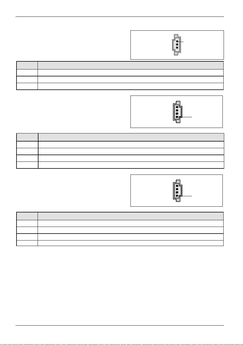
Audio S/PDIF
Pin Signal
1VCC
2 SPDIF out
3GND
1
AUX-Audio In
1
Pin Signal
1 Left AUX audio input
2 Analog GND
3 Analog GND
4 Right AUX audio input
CD-ROM Audio In
1
Pin Signal
1 Left CD audio input
2 CD GND
3 CD GND
4 Right CD audio input
10 - Deutsch A26361-D1555-Z121-2-6319
Page 21
Pinbelegung interne Anschlüsse
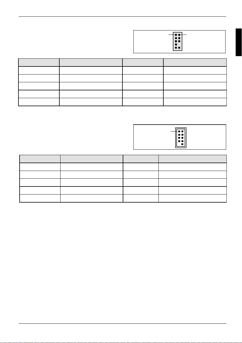
Audio-Bedienfeld / Audio front panel
Pin Signal Pin Signal
1 Micro input 2 Analog GND
3 Micro bias 4 Analog VCC
5 Right line output 6 Right line return
7 Not connected 8 Key
9 Left line output 10 Left line return
Wird das Audio-Bedienfeld nicht benutzt, müssen Sie S t eckbrücken auf die Pinpaare 5/6 und 9/ 10
stecken.
FireWire / IEEE 1394
Pin Signal Pin Signal
1 TPA+ 2 TPA3 GND 4 GND
5 TPB+ 6 TPB7 +12 V 8 +12 V
9 Key 10 GND
1 2
1
A26361-D1555-Z121-2-6319 Deutsch - 11
Page 22
Pinbelegung interne Anschlüsse
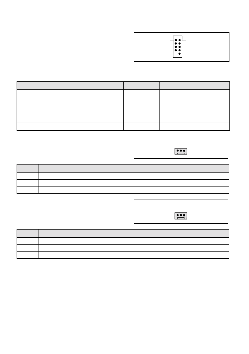
USB
1 2
C/D - dual channel
E/F - dual channel
(internal or external via spec i al cable)
Pin Signal Pin Signal
1 VCC C 2 VCC D
3 Dat a negative C 4 Data negat i ve D
5 Data positive C 6 Data positive D
7 GND 8 GND
9 Key 10 Not connected
Lüfter 1 / Fan 1
(processor fan - only for 3 pin f ans)
Pin Signal
1GND
2 Fix Fan voltage (+12 V, max. 1 A)
3 Fan sense
Lüfter 2 / Fan 2
1
1
(system fan - only for 3 pin fans)
Pin Signal
1GND
2 Fix Fan voltage (+12 V, max. 1 A)
3 Fan sense
12 - Deutsch A26361-D1555-Z121-2-6319
Page 23
Pinbelegung interne Anschlüsse
Stromversorgung ATX /
1
Power supply ATX
11
Pin Signal Pin Signal
1 +3.3V(P2V2P) 11 +3.3V(P2V2P)
2 +3.3V(P2V2P) 12 -12V (P12V N)
3GND13GND
4 +5V (VCC) 14 PS on (low asserted)
5GND15GND
6 +5V (VCC) 16 GND
7GND17GND
8 Powergood (high asserted) 18 -5V (5PVN)
9 +5V Auxiliary (VCC Aux) 19 +5V (VCC)
10 +12V (P12VP) 20 +5V (VCC)
Stromversorgung ATX12 V / Power supply ATX12 V
Pin Signal Pin Signal
1 GND 2 GND
3 +12 V 4 +12 V
13
A26361-D1555-Z121-2-6319 Deutsch - 13
Page 24
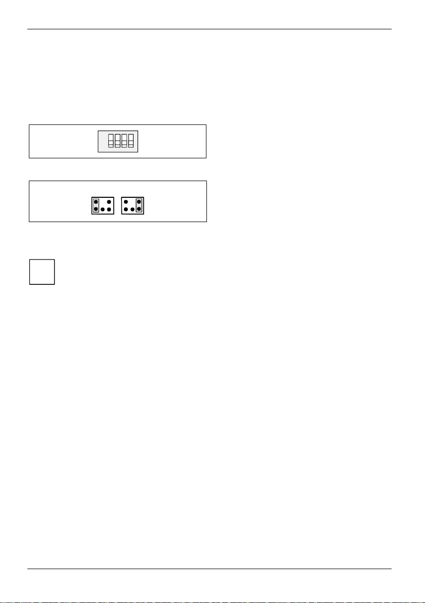
Einstellungen mit Schaltern und Steckbrücken
Ihr Mainboard ist alternativ mit Schaltern oder Steckbrücken bestückt. Die Position der Schal ter oder
Steckbrücken finden S ie auf der Seite "Umschlag/ Cover".
ON
1234
Schalter 1 = System- und BIOS-Setup-Passwort
umgehen
Schalter 2 = System -B IOS wiederherstellen
Schalter 3 = muss immer auf off gestellt sein
Schalter 4 = muss immer auf off gestellt sein
21
Die Taktfrequenz des Prozessors wird automatisc h ei ngestellt.
i
System- und BIOS-Setup-Passwort umgehen - Schalter 1 / Pi npaar 1
Der Schalter 1 / Pinpaar 1 ermöglicht das Umgehen des System- und BIOS-Setup-Passwort s.
On Das System- und B IOS-Setup-Passwort wird beim Einschalten des Gerätes
Off Das System- und BIOS-Setup-Passwort muss beim E i nschalten des Gerätes
System-BIOS wiederherstellen - Schalter 2 / P i npaar 2
Der Schalter 2 / Pinpaar 2 ermöglicht das Wiederherstellen des System-BIOS nach einem
fehlerhaften Update. Zum Wiederherst el l en des System-BIOS benöt i gen Sie eine "Flash-BIOSDiskette" (siehe K api tel "BIOS-Update").
On Das System-BIOS startet vom Di skettenlaufwerk A: und di e ei ngel egte "Flash-BIOS-
Off Normaler B etrieb (Standardeinstellung).
Reserviert - Schalter 3 und Schalter 4 (wenn vorhanden)
Schalter 3 und 4 sind reservi ert . Die Schalterstellung spielt keine Rolle.
übersprungen und kann geändert werden.
eingegeben werden.
Diskette" überschrei bt das System-BIOS auf dem Mainboard.
Pinpaar 1 gesteckt =
System- und BIOS-Setup-Passwort umgehen
Pinpaar 2 gesteckt =
System-BIOS wi ederherstellen
Jede andere Einstellung =
Auslieferungszust and; Steckbrücke ohne
Funktion
14 - Deutsch A26361-D1555-Z121-2-6319
Page 25
Erweiterungen / Hochrüsten
Bei allen in diesem Kapitel beschriebenen Arbeiten verlass en S i e zuerst den
Energiesparmodus, bevor Sie das Gerät ausschalten und ziehen S i e dann den
!
Netzstecker aus der S chutzkontakt-St eckdose!
Auch wenn Sie das Gerät heruntergefahren haben, stehen Teile des Gerätes (z. B .
Speichermodule, AGP- und PCI-Erweiterungsbaugruppen) noch unter Spannung.
Prozessor tauschen
Technische Daten
• Pentium 4 mit 400/533 MHz Prozessor Syst em Bus (PSB) in der Bauf orm mPGA478
• Celeron mit 400 MHz Prozess or System Bus in der Bauf orm m PGA478
Eine aktuelle Liste der v on di esem Mainboard unterstützten Prozessoren finden Sie im I nternet
unter: www.fujitsu-siemens.de/mainboards.
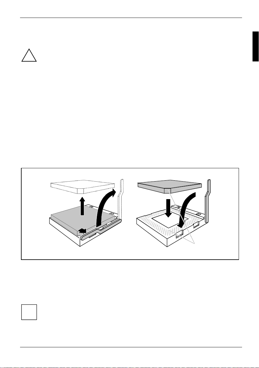
Prozessor ausbauen/einbauen
Ê Entfernen Sie einen eventuell vorhandenen Lüfter und den Kühlkörper.
2
2
3
3
1
1
Ê Drücken Sie den Hebel in Pfeilrichtung (1) und schwenken Sie ihn bis zum Anschlag nach
oben (2).
Ê Heben Sie den alten Prozessor aus dem Steck pl atz (3).
Ê Stecken Sie den neuen Prozessor so in den St eckplatz, dass die abgeschrägte Ecke des
Prozessors mit der Codi erung am S teckplatz (A) von der Lage her übereinstimmt (4).
Die abgeschrägte Ecke des Prozessors kann auch an einer anderen S t el l e sein als in der
Abbildung dargestellt.
i
Ê Schwenken Sie den Hebel nach unten, bis er spürbar einrastet (5).
A26361-D1555-Z121-2-6319 Deutsch - 15
4
4
5
5
A
A
Page 26
Prozessor tauschen
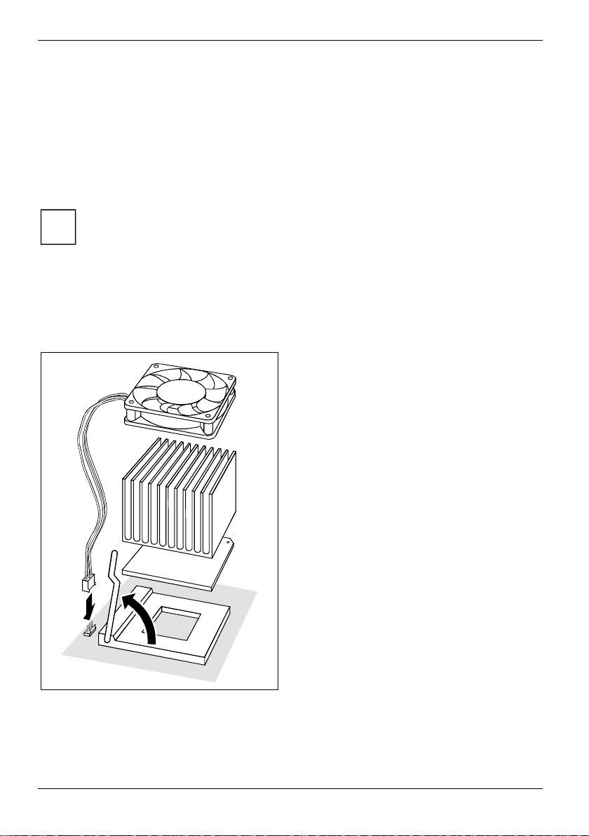
Kühlkörpermontage
Verwenden Sie unbedingt Wärmeleitmateri al zwischen Prozessor und K ühl körper. Wenn auf dem
Kühlkörper bereits ein Wärmeleit pad (gum m i artige Folie) aufgebracht ist, verwenden Sie dieses.
Ansonsten müssen Si e ei ne sehr dünne Schicht Wärmeleitpas te auftragen.
Wärmeleitpads können Sie nur einmal benut zen. Wenn Sie den Kühlkörper abnehmen, müs sen Sie
ihn reinigen und neue Wärmeleitpaste auft ragen, bevor Sie ihn erneut montieren.
Bitte beachten Sie, dass je nach verwendetem Kühlk örper unt erschiedliche Kühlkörperhalt erungen
auf dem Mainboard benötigt werden.
Wenn auf der Unterseite des Mainboards ei ne Gegenhal teplatte zur Versteif ung m ontiert
ist, dürfen keine Kühlkörper vom Typ "Intel Boxed" verwendet werden. Die Halteklammern
i
des Kühlkörpers werden sonst beschädigt.
Beim Verwenden eines Kühlkörper "Intel Boxed" muss das M ai nboard um gerüstet
werden. Dieser Umrüstsatz liegt entweder dem Mainboard bei oder ist separat erhältlich.
Wenn keine Gegenhalteplatte montiert ist, können Sie sowohl K ühl körper "Intel Boxed"
als auch Standard-Kühlkörper v erwenden. Wenn Sie den Kühlkörper "Intel Box ed"
verwenden, biegt sich das M ai nboard wegen des starken Drucks der Halteklammern
durch. Dieses Verhalten ist von Intel so spez i fiziert.
Ê Je nach Ausbau-Variante müssen Sie eine
Schutzfolie vom Kühlkörper abziehen oder
den Kühlkörper mit Wärmeleitpas te
bestreichen, bevor Sie den ihn auf setzen.
Ê Je nach Prozessor-Variante werden für die
Befestigung des Kühlkörpers noch Klammern
mitgeliefert, die den Kühlkörper fixieren.
Ê Wenn Sie den optionalen Lüfter montiert
haben, stecken Sie den Lüft erstecker auf
den entsprechenden Anschluss auf dem
Mainboard.
16 - Deutsch A26361-D1555-Z121-2-6319
Page 27
Hauptspeicher hochrüsten
Hauptspeicher hochrüsten
Technische Daten
Technologie: DDR 266 oder DDR 333 unbuffered DIMM Module
Gesamtgröße: 32 Mbytes bis 3 Gbyte DDR 266 S DRAM
Modulgrößen: 32, 64, 128, 256, 512 oder 1024 Mbyte pro Modul
Eine aktuelle Liste der f ür di eses Mainboard empfohlenen Speichermodul e finden Sie im Internet
unter: www.fujitsu-siemens.de/mainboards.
Es muss mindest ens ein Speichermodul eingebaut sein. Bei DDR 266 Modulen können bis zu drei
double-sided Speichermodule verwendet werden. Bei DDR 333 können bis zu zwei double-si ded,
drei single-sided oder ein double-sided mi t zwei single-sided Speic herm odul en verwendet werden.
Speichermodule mit unterschiedlicher Speicherkapaz i t ät können kombiniert werden.
!
Speichertaktgeschwindigkeit
Die Speichertaktgesc hwindigkeit wird beeinfluss t von Chipset und Syst em bus des Prozessors. Di e
Tabelle zeigt die Geschwindigkeit des Speichers in Abhängi gkeit vom Prozessor S ystem Bus.
184-Pin; 2,5 V; 64 Bit, kein ECC
32 Mbytes bis 2 Gbyte DDR 333 SDRAM
Es dürfen nur ungepufferte 2,5 V-S pei chermodule verwendet werden. Gepufferte
Speichermodule sind nicht erl aubt.
DDR-DIMM-Speichermodule müssen der PC2100- oder PC2700-Spezifikati on
entsprechen.
Prozessor System Bus (MHz) DDR333 (MHz) DDR266 (MHz)
533 333 266
400 333 266
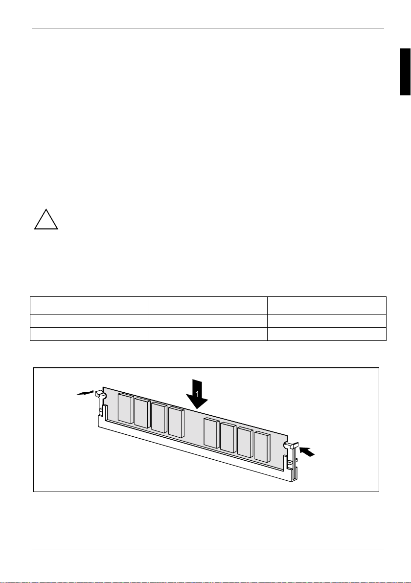
Speichermodul einbauen
2
2
Ê Klappen Sie die Halterungen des entsprechenden Einbauplatz es an beiden Seiten nach außen.
Ê Stecken Sie das Speichermodul in den Einbaupl at z (1).
Ê Klappen Sie dabei die seitlichen Halterungen hoch, bi s sie am Speichermodul einrasten (2).
A26361-D1555-Z121-2-6319 Deutsch - 17
Page 28
AGP-Grafikkarten hochrüsten
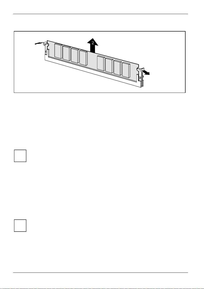
Speichermodul ausbauen
1
1
Ê Drücken Sie die Halterungen auf der linken und auf der rechten S ei t e nach außen (1).
Ê Ziehen Sie das Speichermodul aus dem Einbauplatz (2).
AGP-Grafikkarten hochrüsten
Technische Daten:
Der AGP-Steckplatz unterstützt die Modi 4x /8x mit 32 Bit und 66 MHz. E s werden ausschließlich
1,5 V AGP-Grafikkart en unt erstützt.
Manche ältere 3,3 V AGP-Grafi kkarten sind wie 1,5 V AGP -Grafikkarten codiert. Die
Installation einer solchen 3,3 V AGP-Grafikkart e kann schwere Beschädigungen am
i
Mainboard und an der AGP-Grafikkarte hervorrufen.
PCI-Karten hochrüsten
Technische Daten:
32 Bit / 33 MHz PCI-Steckplätze
5 V und 3,3 V Versorgungsspannung
3,3 V Hilfsspannung
PCI-Bus-Interrupts - Auswahl des richtigen PCI-Steckplatzes
Um optimale Stabilität, Performance und Kompat ibilität zu erreichen, vermeiden Sie die
mehrfache Nutzung von ISA I RQs oder PCI IRQ Lines (IRQ Sharing). S ol l t e IRQ Sharing
i
nicht zu umgehen sein, so müssen alle beteiligten Geräte und deren Treiber IRQ Sharing
unterstützen.
PCI IRQ Lines verbinden AGP-, P CI-Steckplätze und Onboard-Komponenten mit dem InterruptController. PCI IRQ Lines s i nd f est auf dem Mainboard verdrahtet.
Welche ISA IRQs den PCI IRQ Lines zugeordnet werden, wird normalerweise automatisch vom
BIOS festgelegt (si ehe Beschreibung "BIOS-Set up" ).
18 - Deutsch A26361-D1555-Z121-2-6319
Page 29
PCI-Karten hochrüsten
Monofunktionale Erweiterungskarten:
Standard-AGP- und PCI-Erweiterungs karten benötigen maximal einen I nt errupt, der als PCIInterrupt INT A bezeichnet wi rd. Erweiterungskarten, die k ei nen I nterrupt benötigen, können in einen
beliebigen Steckplatz ei ngebaut werden.
Multifunktionale Erweiterungskarten oder Erweiterungskarten mit integrierter P CI -PCI Bridge:
Diese Erweiterungskarten benötigen bi s zu vier PCI-Interrupts: INT A, INT B, INT C, INT D. Wi e
viele und welche dieser Interrupt s verwendet werden, entnehmen Sie der mitgelieferten
Dokumentation der Karte.
Die Zuordnung der PCI-Interrupts zu den PCI IRQ Lines finden Sie in der folgenden Tabelle:
Onboard Controller PCI-Steckplatz
USB 1.1 AC97
PCI
Interrupt
Line
1st2nd3
1 (A) ---- - - - - ACBAD C
2 (B) ---- B- - - BDCBAD
3 (C) ---- - C- - - ADCB A
4 (D) ---- - - - D- BADC B
5 (E) E------------6 (F) -F-----------7 (G) --G----------8 (H) ---H- - - - - - - - - -
rd
USB 2.0
SMBus
Audio
Modem
LAN
1 2 3 4 5
AGP
Verwenden Sie zuerst PCI-Steckplätze, die über eine einz i ge PCI IRQ Line verfügen (kein IRQ
Sharing). Wenn Sie einen anderen PCI-Stec kplatz mit IRQ Sharing benut zen müssen, überprüfen
Sie, ob die Erweiterungskart e I RQ Sharing mit den anderen Geräten auf dieser PCI IRQ Line
einwandfrei unterstützt. Auch die Treiber aller Karten und Komponent en an di eser PCI IRQ Line
müssen IRQ Sharing unterstützen.
A26361-D1555-Z121-2-6319 Deutsch - 19
Page 30
PCI-Karten hochrüsten
Lithium-Batterie austauschen
Damit die Systeminformation dauerhaft gespeichert werden kann, ist eine Lithium-Batterie
eingebaut, die den CMOS-Speicher mi t Strom versorgt. Wenn die Spannung der B at terie zu niedrig
ist oder die Batterie leer ist, wird eine entsprechende Fehlermeldung ausgegeben. Die LithiumBatterie muss dann gewechs el t werden.
Bei unsachgemäßem Austausch der Lithium-Batterie bes t eht Explosionsgefahr!
!
Die Lithium-Batterie darf nur durc h i dentische oder vom Hersteller empfohlene Typen
ersetzt werden.
Die Lithium-Batterie gehört ni cht in den Hausmüll. Sie wi rd vom Hersteller, Händler oder
deren Beauftragten kostenlos zurückgenommen, um sie einer Verwertung bzw.
Entsorgung zuzuführen.
Die Batterieverordnung verpfli chtet Endverbraucher, defek t e oder verbrauchte Batterien
an den Vertreiber oder an die dafür eingerichteten Rücknahmestellen zurückzugeben.
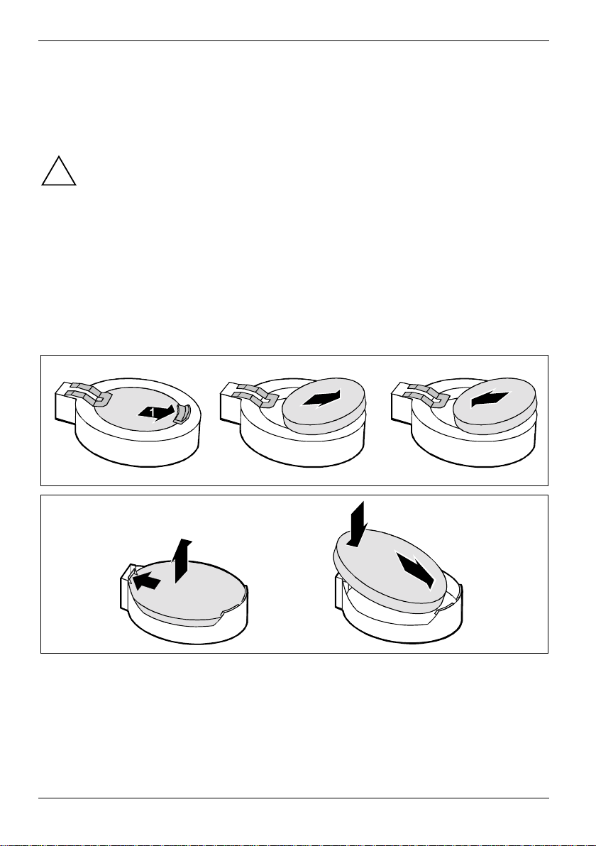
Achten Sie beim Aust ausch unbedingt auf die richtige P ol ung der Li thium-Batterie Pluspol nach oben!
Die Halterung der Lithium-Batteri e gi bt es in verschiedenen Ausführungen, die sich in ihrer
Funktionsweise nicht unterscheiden.
2
4
2
1
3
3
Ê Drücken Sie die Rastnase in Pfeilrichtung, die Batterie springt etwas aus der Halterung
heraus (1).
Ê Entfernen Sie die Batterie (2).
Ê Schieben Sie die neue Lithium-Batterie des ident i schen Typs in die Halterung (3) und drück en
Sie sie nach unten, bis sie einrastet (4).
20 - Deutsch A26361-D1555-Z121-2-6319
Page 31

BIOS-Update
BIOS-Update
Wann sollte ein BIOS-Update durchgeführt werden?
Fujitsu Siemens Computers stellt neue B I OS -V ersionen zur Verfügung, um die Kompatibilität zu
neuen Betriebssystemen, zu neuer Software oder zu neuer Hardware zu gewährleisten. Außerdem
können neue BIOS-Funktionen integri ert werden.
Ein BIOS-Update sollte auch immer dann durchgeführt werden, wenn ein Probl em besteht, das sich
durch neue Treiber oder neue Software nicht beheben läs st.
Wo gibt es BIOS-Updates?
Im Internet unter www.fujitsu-siemens.de/mainboards finden Sie die BIOS-Updates.
Wie funktioniert ein BIOS-Update?
Sie haben zwei Möglichkeit en:
1. BIOS-Update unter DOS mit startfähiger BIOS-Update-Diskette - Kurz beschreibung
Ê Laden Sie die Update-Datei von unserer Internet-Seite auf Ihren PC.
Ê Legen Sie eine leere Diskette (1,44 MB) ein.
Ê Führen Sie die Update-Datei aus (z. B. 1522103.EXE).
Ê Es wird eine startfähige Update-Diskette erstellt. Lassen Sie diese Diskette im Laufwerk.
Ê Starten Sie den PC neu.
Ê Folgen Sie den Bildschirmanweisungen.
Detaillierte Informationen zum BIOS-Update unter DOS finden Sie im Handbuch zum
"BIOS-Setup" (CD "Drivers & Utilities").
i
2. BIOS-Update unter Windows mit dem Utility DeskFlash
Ein BIOS-Update kann mit dem Utility DeskFlash auch direkt unt er Wi ndows durchgeführt werden.
DeskFlash befindet si ch auf der CD "Drivers & Utilities“ (ab CD-Version 2001. 05 mit DeskView
V5.0). In der Datei Liesmich bzw. Readme im Unterverzeichnis DeskFlash finden Sie dazu die
Installationsanleitung. Weitere Informationen zu DeskFlash finden Sie in der Dat ei DeskView.PDF und
in der Online-Hilfe von DeskVi ew
OEM
.
OEM
BIOS-Recovery - System-BIOS wiederherstellen
Alle BIOS-Einstel l ungen werden auf Standardwerte zurückgeset zt.
i
Ê Öffnen Sie das Gerät wie in der Betriebsanleitung bes chrieben.
Ê Stellen Sie den Schalter für "Sys t em-BIOS wiederherstellen" auf ON.
Ê Schließen Sie das Gerät wie in der Betriebsanleit ung beschrieben.
Ê Legen Sie eine BIOS-Update-Diskette ein und st art en Sie den PC.
Ê Achten Sie auf die Lautsprechertöne. Das Wiederherstellen des BIOS war erfolgrei ch, wenn
Sie die Tonfolge "kurz-kurz —l ang—l ang—l ang" hören und di e Di skettenzugriffsk ontrolle
erloschen ist. Der Vorgang k ann ei ni ge M i nuten dauern.
A26361-D1555-Z121-2-6319 Deutsch - 21
Page 32

Microcode-Update
Ê Öffnen Sie das Gerät wie in der Betriebsanleitung bes chrieben.
Ê Stellen Sie den Schalter für "Sys t em-BIOS wiederherstellen" auf OFF.
Ê Schließen Sie das Gerät wie in der Betriebsanleit ung beschrieben.
Ê Nehmen Sie die Diskette aus dem Diskettenlaufwerk.
Ê Starten Sie den PC und rufen Sie das BIOS-Setup auf.
Ê Wählen Sie
Einstellung auf Yes.
im Menü Advanced den Menüpunkt Reset Configuration Data und ändern Sie die
Ê Beenden Sie das BIOS-Setup und speichern Sie die Änderungen.
Das BIOS-Recovery ist abgeschlossen. Das S ystem startet.
Detaillierte Informationen zum BIOS-Recov ery finden Sie im Handbuch "BIOS-Setup" (CD
"Drivers & Utilities").
i
Microcode-Update
Was ist ein Microcode-Update?
Da es für Prozessoren keine Treiber gibt , bietet Intel ab den Prozessoren der P6-Familie (Pentium
Pro) die Möglichkeit, den B efehlssatz (Microc ode) des Prozessors zu aktualisieren. So können
kleinere Fehler ausgebessert und die P erformance gesteigert werden.
Um bestmögliche Performance und einen fehlerfreien Betrieb zu garant i eren, empfiehlt Intel, den
Microcode für jeden neuen Prozessor zu aktualisieren. I nt el bezeichnet eine Nutzung des
Prozessors ohne Microc ode-Update als Betrieb außerhalb der Spezifi kation.
Sicherheit für den Prozessor auf Fujitsu Siemens Computers Mainboards
Wird der Prozessor mit einem al ten oder falschen Microcode genut zt, kann ein fehlerfreier Bet ri eb
nicht gewährleistet werden. Fuj i t su Siemens Computers hat des hal b auf seinen Mainboards eine
Funktion implementiert, di e den S tartvorgang unterbricht, fal l s kein passender Microcode f ür den
installierten Prozessor vorhanden is t . Die ausgegebene Fehlermeldung lautet
Patch for installed CPU not loaded. Please run the bios flash update
diskette.
Diese Meldung erscheint erst dann nicht mehr, wenn das Microcode-Update durchgeführt wurde.
Falls der Computer trotzdem ohne Mi crocode-Update betrieben wird, ist ein fehlerfreier Betrieb nicht
gewährleistet.
Wann sollte ein Microcode-Update durchgeführt werden?
Ein Microcode-Update sollte nach der Installation eines neuen Prozessors durchgeführt werden.
Im Gegensatz zum BI OS -Update wird hier nur eine aktualisierte V ersion des Befehlssatzes des
Prozessors gespeic hert . Das System-BIOS bleibt davon unberührt.
22 - Deutsch A26361-D1555-Z121-2-6319
Page 33

Treiber
Microcode Update unter DOS mit startfähiger Microcode-Update-Diskette - Kurzbeschreibung
Ê Laden Sie die Update-Datei von unserer Internet-Seite auf Ihren PC.
Ê Legen Sie eine leere Diskette (1,44 MB) ein.
Ê Führen Sie die Update-Datei unter DOS aus (z. B. 1495101.EXE).
Ê Es wird eine startfähige Update-Diskette erstellt. Lassen Sie die Diskette im Lauf werk.
Ê Starten Sie den PC neu.
Ê Folgen Sie den Bildschirmanweisungen.
Um festzustellen, ob das neueste Microcode-Update gel aden wurde, kann die sogenannte Patch-ID
des Prozessors ausgel esen werden.
Ê Drücken Sie im BIOS-Setup die Taste [F1].
Auf der angezeigten Informati onsseite finden Sie den Eint rag CPU / Patch ID.
Eine Liste mit den akt uel l en P rozessoren und den zugehörigen Patch-IDs finden Sie im Internet.
Falls der Prozessor nicht erkannt wird, benötigen Sie zusätzlich das Microcode-UpdateTool für Prozessoren der P6-Familie.
i
Treiber
Nur wenn auf Ihrem System keine Treiber installiert sind oder Sie diese aktualisieren möchten,
gehen Sie wie folgt vor:
Ê Legen Sie die CD "Drivers & Utilities Collection" in das CD-ROM-Laufwerk.
Ê Wenn die CD nicht automatisch startet, rufen Sie das Programm START.EXE im CD-ROM -
Verzeichnis auf.
Ê Wählen Sie DeskUpdate - Vollautomatische Installation aus.
Ê Folgen Sie den Bildschirmanweisungen.
A26361-D1555-Z121-2-6319 Deutsch - 23
Page 34

Anhang
Elektrische Eigenschaften
Belastbarkeit für Anschlüsse und Sicherungen
Achten Sie darauf, dass di e angeschlossenen Geräte die Ansc hl üsse nicht überlasten.
i
Sicherung No. Absicherung Anschluss Maximale Belastbarkeit
- - Lüfter1, Lüfter2 Je 1000 mA
1 750 mA Tastatur Nic ht spezifiziert
Maus Nicht spezifiz i ert
VGA-Anschluss Minimum 50 mA
2 2000 mA USB-Ansc hl uss A
USB-Anschluss B
USB-Anschluss C
USB-Anschluss D
3 2000 mA USB-Ansc hl uss E
USB-Anschluss F
Die Sicherungen auf diesem Mainboard sind mehrfach verwendbar (Polyf uses). Kurz nach
Beseitigung des Fehlerzustandes setzen sich die Sicherungen wieder in den Ursprungszust and
zurück.
500 mA
500 mA
Strombedarf des Mainboards
Sie benötigen für dieses Mainboard ei n Pentium4-Netzteil nach der A T X 12V-Spezifikation. Wenn
Sie keinen PC von Fujitsu Siemens Computer haben, stellen Sie sicher, dass das Netzteil die
benötigten Stromstärk en zur Verfügung stellt.
Quelle Spannung Maximale
Abweichung
ATX12V Netzteil +12 V ±5 % 12 A
ATX12V Netzteil -12 V ±10 % 0,05 A
ATX12V Netzteil +5.0 V ±5 % 19,5 A
ATX12V Netzteil +3.3 V ±5 % 3,7 A
Standby-Spannung Netzteil +5.0 V SB ±5 % 2 A
Die Angaben gelten für die Onboard-Komponenten und stellen den ungünstigsten Fall dar.
Zusätzlich werden für PCI auf 3,3 V mindestens 350 mA und für USB auf 5 V je 500 mA pro
angeschlossenem Gerät benötigt.
24 - Deutsch A26361-D1555-Z121-2-6319
Maximaler Strom
Page 35

APM und ACPI Systemstatus, Stromsparmodi
APM und ACPI Systemstatus, Stromsparmodi
Systemstatus ACPI
Normaler Betrieb G0 S0 On An Normal
Einfacher Energie-
sparmodus
Maximaler
Energie-
sparmodus**
"Save-To-RAM"
Maximaler
Energie-
sparmodus
"Save-To-Disk"
"Soft Off" G2 S5 Soft Off Nahe Null Volle Bootzeit
Mechanisch Aus G3 Off
* G = Globaler Status; S = Systemstatus
** Das Netzteil muss ausreichend belastbare 5 V Standby -S pannung zur Verfügung stellen.
Um Wake-up-Funktionen nutzen zu können, muss die Stromversorgung eine 5 V-Hilfsspannung
(5V SB) von mindestens 1 A zur Verfügung stellen.
Status*
G1
APM
Status
S1 Standby Fast wie Normal fast sofort
S3
S4 Wake-up-
Power
LED
blinkt
Aus
Strom-
verbrauch
RAM-,
Wake-up-
Komponenten
Komponenten
Null Volle Bootzeit
Aufwach-
zeit
ca. 5s
ca. 20s
A26361-D1555-Z121-2-6319 Deutsch - 25
Page 36

Mainboard-Revision und BIOS-Version
Mainboard-Revision und BIOS-Version
Die Kompatibilität z. B. mit neuen Prozes soren kann abhängig von der verwendeten BIOS-V ersion
oder dem Revision-Stand des Mainboards sein. Sie finden die CPU- und BIOS-Kompatibilitätslisten
im Internet unter www.fujitsu-siemens.de/mainboards.
Mainboard-Revision
Der Revision-Stand des Mainboards identifiziert genau, welches Mainboard Sie besitzen. Sie finden
ihn auf einem Aufkleber an einer Kant e des Mainboards:
D1555-C12 GS 1
05618476
Beispiel Mainboard-Revisi on
BIOS-Version
Die BIOS-Version kann im BIOS-Setup angezeigt werden.
Ê Drücken Sie beim Starten [F2], um in das BI OS -Setup zu gelangen.
Ê Drücken Sie [F1].
Auf der angezeigten Informati onsseite ist die BIOS-Version unter dem Eintrag BIOS Release
angegeben.
26 - Deutsch A26361-D1555-Z121-2-6319
Page 37

Fehlermeldungen
In diesem Kapitel finden S i e di e Fehl erm el dungen, die von den Mainboards ausgegeben werden.
Available CPUs do not support the same bus frequency - System halted!
Memory type mixing detected
Non Fujitsu Siemens Memory Module detected - Warranty void
There are more than 32 RDRAM devices in the system
Überprüfen Sie, ob sich die Sy stemkonfiguration geändert hat. Korrigieren Sie diese
gegebenenfalls.
BIOS update for installed CPU failed
Diese Meldung erscheint, wenn i m S ystem-BIOS der für den ges t eckten Prozessor
erforderliche Mikrocode-Update ni cht enthalten ist.
Ê Starten Sie das System mit eingelegter Flash-BIOS-Diskette.
Ê Brechen Sie den normalen Flash-Vorgang ab, d.h., beantworten S i e di e Frage, das Flash-
BIOS-Update durchzuführen, m i t
n Ú
Ê Um das Flash-BIOS-Update für den Prozessor durc hzuführen, geben Sie ein:
flashbioË/p6 Ú
Check date and time settings
Das Datum und die Uhrzeit des Systems sind ungültig. Stellen Sie das aktuel l e Datum und die
aktuelle Uhrzeit im Menü Main des BIOS-Setup ein.
CPU ID 0x failed
Schalten Sie den Server aus und wi eder ei n. Wenn die Meldung weiterhin erscheint, stellen Sie
im BIOS-Setup im Menü Server - CPU Status den entsprechenden Prozessor auf Disabled und
wenden Sie sich an unsere Verkauf sstelle oder unseren Servic e.
CPU mismatch detected
Sie haben den Prozessor ausgewechselt oder die Frequenzeinstellung geändert. Die
Kenndaten des Prozessors haben sich damit geändert. Bes t ätigen Sie diese Änderung, indem
Sie das BIOS-Setup aufrufen und wieder verlassen.
Diskette drive A error
Diskette drive B error
Überprüfen Sie im BIOS-Setup, im Menü Main, den Eintrag für das Diskettenl aufwerk.
Überprüfen Sie die Anschlüsse des Diskettenlaufwerks.
A26361-D1555-Z121-2-6319 Deutsch - 27
Page 38

Fehlermeldungen
DMA test failed
EISA CMOS not writable
Extended RAM Failed at offset: nnnn
Extended RAM Failed at address line: nnnn
Failing Bits: nnnn
Fail-Safe Timer NMI failed
Multiple-bit ECC error occurred
Memory decreased in size
Memory size found by POST differed from EISA CMOS
Single-bit ECC error occurred
Software NMI failed
System memory exceeds the CPU’s caching limit
System RAM Failed at offset: nnnn
Shadow RAM Failed at offset: nnnn
Schalten Sie das Gerät aus und wi eder ei n. Wenn die Meldung weiterhin erscheint, wenden
Sie sich an Ihre Verkauf sstelle oder an unseren Servic e.
Failure Fixed Disk 0
Failure Fixed Disk 1
Fixed Disk Controller Failure
Überprüfen Sie im BIOS-Setup, im Menü Main, die E i nträge für das Festplattenlauf werk und im
Menü Advanced - Peripheral Configuration den Eintrag für den IDE-Laufwerks-Controller.
Überprüfen Sie die Anschlüss e und Steckbrücken des Festplattenlaufwerks.
Incorrect Drive A - run SETUP
Incorrect Drive B - run SETUP
Stellen Sie im BIOS-Setup, im Menü Main , den Eintrag für das Diskett enlaufwerk richtig ein.
Invalid NVRAM media type
Schalten Sie das Gerät aus und wi eder ei n. Wenn die Meldung weiterhin erscheint, wenden
Sie sich an Ihre Verkauf sstelle oder an unseren Servic e.
Invalid System Configuration Data
Stellen Sie im BIOS-Setup, im Menü Advanced den Eintrag Reset Configuration Data auf Yes.
Invalid System Configuration Data - run configuration utility
Press F1 to resume, F2 to Setup
Wurde der Rechner während des Systemstarts ausgeschaltet, kann diese Fehlermeldung
auftreten.
Rufen Sie das BIOS-Setup auf und wechseln Si e zum Menü Advanced. Wählen Sie dort den
Menüpunkt Reset Configuration Data aus und ändern Sie die Einstellung auf Yes. Speichern Sie
die Änderung und verlassen Sie das BIOS-Setup. S tarten Sie den Rechner neu.
Keyboard controller error
Schließen Sie eine andere Tastatur oder M aus an. Wenn die Meldung weiterhin erscheint ,
wenden Sie sich bitte an Ihre V erkaufsstelle oder unseren Service.
Keyboard error
Kontrollieren Sie, ob die Tastatur korrek t angeschlossen ist.
Keyboard error nn
nn Stuck Key
Lösen Sie die Taste auf der Tastat ur ( nn i st der Hexadezimalcode für die Taste).
28 - Deutsch A26361-D1555-Z121-2-6319
Page 39

Fehlermeldungen
Missing or invalid NVRAM token
Schalten Sie das Gerät aus und wi eder ei n. Wenn die Meldung weiterhin erscheint, wenden
Sie sich bitte an Ihre V erkaufsstelle oder unseren Service.
Monitor type does not match CMOS - RUN SETUP
Stellen Sie im BIOS-Setup, im Menü Main , den Eintrag für den Bildschirm t yp richtig ein.
On Board PCI VGA not configured for Bus Master
Stellen Sie im BIOS-Setup, im Menü Advanced i m Untermenü PCI Configuration, den Eintrag
Shared PCI Master Assignment auf VGA.
One or more RDRAM devices are not used
One or more RDRAM devices have bad architecture/timing
One or more RDRAM devices are disabled
Wenden Sie sich bitte an Ihren A dministrator oder unseren Service.
Operating system not found
Überprüfen Sie im BIOS-Setup, im Menü Main, die E i nträge für das Festplattenlauf werk und das
Diskettenlaufwerk, sowie die Einträge für Boot Sequence.
Parity Check 1
Parity Check 2
Schalten Sie das Gerät aus und wi eder ei n. Wenn die Meldung weiterhin erscheint, wenden
Sie sich an Ihre Verkauf sstelle oder an unseren Servic e.
Previous boot incomplete - Default configuration used
Wenn Sie die Funktionstast e [F 2] drück en, können Sie im BIOS-Setup die Einstellungen prüfen
und korrigieren. Wenn Sie die Funktionstaste [F1] drücken, startet das System m i t der
unvollständigen Systemkonfiguration. Wenn die Meldung wei t erhi n erscheint, wenden Sie sic h
an Ihre Verkaufsstell e oder an unseren Service.
Real time clock error
Rufen Sie das BIOS-Setup auf und tragen Sie im M enü Main di e ri chtige Uhrzeit ein. Wenn die
Meldung weiterhin erscheint, wenden Sie sich bitte an Ihre Verkaufsstelle oder unseren
Service.
Service Processor not properly installed
Der Servermanagement-Controller ist nicht richt i g ins talliert. Wenn die Meldung weiterhin
erscheint, wenden Sie sich bitte an Ihre Verkaufsstelle oder unseren Service.
Storage Extension Group = xy
Configuration error, x Storage Extensions(s) found, configured are y
SE(s).
Device List: k1, k2 ...
Die angegebene Anzahl der Speichererweiterungs ei nhei ten (SE) im BIOS-Setup Menü Server Storage Extensions - Number of connected SE ist falsch. Prüfen Sie, wie vi el e S E innerhalb der
Gruppe am Server angeschlossen s ind und ändern Sie die Einstellung im BIOS-Setup. P rüfen
Sie, ob Sie eine Geräte-ID doppelt vergeben haben.
xy = Gruppennummer
x = Anzahl der gefundenen SE am Kom m uni kationsbus
y = Anzahl der in Number of connected SE eingetragenen SE
k1, k2 ... = Geräte-ID der gefundenen Speichererweiterungseinheiten
A26361-D1555-Z121-2-6319 Deutsch - 29
Page 40

Fehlermeldungen
System battery is dead - Replace and run SETUP
Tauschen Sie die Lithium-Bat terie auf dem Mainboard aus und führen Sie die E i nstellungen im
BIOS-Setup erneut durch.
System Cache Error - Cache disabled
Schalten Sie das Gerät aus und wi eder ei n. Wenn die Meldung weiterhin erscheint, wenden
Sie sich an Ihre Verkauf sstelle oder an unseren Servic e.
System CMOS checksum bad - - Default configuration used
Rufen Sie das BIOS-Setup auf und korrigieren Sie di e zuletzt vorgenommenen Eint räge oder
stellen Sie die Standardeint räge ei n.
System Management Configuration changed or Problem occurred
Ein Systemlüft er oder S ystemsensor ist ausgefallen. Überprüfen Sie die Funkt i on der
Hardware.
System timer error
Schalten Sie das Gerät aus und wi eder ei n. Wenn die Meldung weiterhin erscheint, wenden
Sie sich an Ihre Verkauf sstelle oder an unseren Servic e.
Uncorrectable ECC DRAM error
DRAM Parity error
Unknown PCI error
Schalten Sie das Gerät aus und wi eder ei n. Wenn die Meldung weiterhin erscheint, wenden
Sie sich bitte an Ihre V erkaufsstelle oder unseren Service.
Verify CPU frequency selection in Setup
Die Frequenzeinstellung für den Proz essor ist ungültig. Korri gi eren S i e di e Einstellung im BIOSSetup.
30 - Deutsch A26361-D1555-Z121-2-6319
Page 41

Glossar
Die unten aufgeführten Fachbegriffe bzw. Abkürzungen stellen k ei ne vollständige Aufzählung al l er
gebräuchlichen Fachbegriffe bzw. Abkürzungen dar.
Nicht alle hier aufgeführten Fac hbegri ffe bzw. Abkürzungen gelten für das beschriebene Mainboard.
ACPI Advanced Configurati on and
Power Management Interface
AC'97 Audio Codec '97 IPSEC Internet Protocol Security
AGP Accelerated Graphics P ort ISA Industrial Standard Architecture
AMR Audio Modem Riser LAN Local A rea Net work
AOL Alert On LAN LSA LAN Desk Service Agent
APM Advanc ed Power Management MCH Memory Controller Hub
ASF Alert S tandard Format MMX MultiMedia eXtension
ATA Advanc ed Technology
Attachment
BIOS Basic Input Output System PCI Peripheral Component
BMC Baseboard Management
Controller
CAN Controller Area Network PXE Preboot eXecut i on Environment
CPU Central Processing Unit RAM Random Access Memory
CNR Communication Network Riser RAMDAC Random Access Memory Digi tal
C-RIMM Continuity Rambus Inline
Memory Module
DIMM Dual Inline Memory Module RIMM Ram bus Inline Memory Module
ECC Error Correcting Code RTC Real-Time Clock
EEPROM Electrical Erasable
Programmable Read Only
Memory
FDC Floppy Di sk Controller SDRAM Synchronous Dynamic Random
FIFO Firs t -In First-Out SGRAM Synchronous Graphic Random
FSB Front Side B us SIMD Streaming Mode I nstruction
FWH Fi rm ware Hub SMBus System Management Bus
GMCH Graphics and Memory Controller
Hub
GPA Graphics Performance
Accelerator
I2C Inter Integrated Circuit VGA Video Graphic A dapter
IAPC Instantly A vailable Power
Managed Desktop PC Design
ICH I/O Controller Hub
IDE Intelligent Drive Electronics
P64H PCI64 Hub
Interconnect
PSB Processor System Bus
Analog Converter
RDRAM Rambus Dynamic Random
Access Memory
SB Soundblaster
Access Memory
Access Memory
(Single Instruction Multiple Data)
SVGA Super Video Graphic Adapter
USB Univers al Serial Bus
WOL Wak e On LA N
A26361-D1555-Z121-2-6319 Deutsch - 31
Page 42

answers
Mainboard D1555
Deutsch / English / Français
2
Technisches Handbuch / Technical Manual
Page 43

Sie haben ...
... technische Fragen oder Probleme?
Wenden Sie sich bitte an:
• Ihren zuständigen Vertriebs part ner
• Ihre Verkaufsst elle
Aktuelle Informationen und Updates (z. B. BIOS-Update) zu unseren Mainboards finden Sie i m
Internet: http://www.fujitsu-siemens.com/mainboards
Are there ...
... any technical problems or other questions you need clarified?
Please contact:
• your sales partner
• your sales outlet
The latest information and updates (e.g. BIOS update) on our mainboards can be found on the
Internet under: http://www.fujitsu-siemens.com/mainboards
Vous avez ...
...des questions t echniques ou des problèmes ?
Veuillez contacter :
• Votre partenaire Commercial
• Votre point de Vente
Les dernières informations ai nsi que les updates (p.ex. B I OS-Update) par rapport à nos cartes
mères sont à votre disposition sur Internet : ht tp://www.fujitsu-siemens.com/mainboards
Page 44

Page 45

Dieses Handbuch wurde auf Recycling-Papier gedruckt.
This manual has been printed on recycled paper.
Ce manuel est imprimé sur du papier recyclé.
Este manual ha sido impreso sobre papel reciclado.
Questo manuale è stato stampato su carta da riciclaggio.
Denna handbok är tryckt på recyclingpapper.
Dit handboek werd op recycling-papier gedrukt.
Herausgegeben von/Published by
Fujitsu Siemens Computers GmbH
Bestell-Nr./Order No.:
Printed in the Federal Republic of Germany
AG 0303 03/03
A26361-D1555-Z121-1-6319
A26361-D1555-Z121-1-6319
Page 46

Deutsch
English
Mainboard D1555
Technisches Handbuch
Technical Manual
Français
Ausgabe März 2003
March 2003 edition
Page 47

Intel, Pentium und Celeron s i nd ei nget ragene Warenzeichen der Intel Corporation, USA.
Microsoft, MS, MS-DOS und Windows sind eingetragene Warenzeichen der Microsoft
Corporation.
PS/2 und OS/2 Warp sind eingetragene Warenz ei chen von International Business Machines,
Inc.
Alle weiteren genannten Warenzeichen s i nd Warenzeichen oder eingetragene Warenzeichen
der jeweiligen Inhaber und werden als geschüt zt anerkannt.
Copyright Fujitsu Si em ens Computers GmbH 2003
Alle Rechte vorbehalten, i nsbesondere (auch auszugsweise) di e der Übersetzung, des
Nachdrucks, der Wiedergabe durch Kopieren oder ähnliche Verfahren.
Zuwiderhandlungen verpflichten zu S chadenersatz.
Alle Rechte vorbehalten, insbesondere für den Fall der Patenterteil ung oder GM -Eintragung.
Liefermöglichkeiten und technische Änderungen vorbehalten.
Dieses Handbuch wurde erstellt von
cognitas. Gesellschaft für Technik-Dokument at i on mbH
www.cognitas.de
Intel, Pentium and Celeron are registered trademarks of Intel Corporation, USA.
Microsoft, MS, MS-DOS and Windows are registered trademarks of Microsoft Corporation.
PS/2 and OS/2 Warp are registered tradem arks of International Busi ness Machines, Inc.
All other trademarks referenced are trademarks or registered tradem arks of their respectiv e
owners, whose protected rights are acknowledged.
All rights, includi ng ri ghts of translation, reproduc t i on by printing, copying or similar methods,
even of parts are reserved.
Offenders will be liable for damages.
All rights, including rights creat ed by patent grant or registration of a utilit y model or design,
are reserved. Delivery subject to availability.
Right of technical modi f i cation reserved.
This manual was produced by
cognitas. Gesellschaft für Technik-Dokument at i on mbH
www.cognitas.de
Page 48

Page 49

Übersicht/Overview Mainboard D1555
Interne Anschlüsse und Steckplätze / Internal
connectors and slots
18
DIMM 2
DIMM 1
CPU
Pent ium 4
DIMM 3
17
16
AGP
PCI 1
15
14
13
12
PCI 2
PCI 3
PCI 4
PCI 5
CNR
1 = Stromversorgung / Power supply
2 = Bedienfeld / Front panel
3 = USB C/D
4 = USB E/F
5 = Diskettenlaufwerk / Floppy disk drive
6 = IDE-Laufwerke 3/4 / IDE-drives 3/4
1
7 = IDE-Laufwerke 1/2 / IDE-drives 1/2
8 = Batterie / Battery
9 = Schalter / Switch
10 = FireWire-Anschluss (1394) / FireWire
connector (1394)
11 = Lüfter 2 / Fan 2
2
12 = AUX-Audio in
13 = CD-Audio in
14 = Audio-Bedienfeld / Audio front panel
15 = Summer / Buzzer
16 = S/PDIF-Anschluss / S/PDIF
3
4
5
6
connector
17 = Prozessor-Stromversorgung /
Processor power supply
18 = Lüfter 1 / Fan 1
Optionale Komponenten / Optional
components
7
8
9
11
10
Externe Anschlüsse / External connectors
1394
Umschaltbar durch Treiber /
Standard 6-channel
Line In (blau/blue)
Line Out (grün/green)
Mic In (rot/red)
Switchable via driver
Rear
Front
Center / Low
Bedienfeld / Front panel
Power On/Off
HD-LED
1)
Reset
1) Cable is not included in the delivery scope.
2) 2-pin or 3-pin conne ctor possible
1)
Power On
1) 2)
LED
1
2
Umschlag /Cpover
Page 50

Contents
Übersicht/Overview Mainboard D1555
Mainboard D1555.............................................................................................................................1
Notational conventions ..............................................................................................................1
Important notes..................................................................................................................................2
Information about boards...........................................................................................................2
List of features...................................................................................................................................3
Special features.........................................................................................................................4
Brief instructions on installing mainboard...........................................................................................5
Prior to installation .....................................................................................................................5
Interfaces and connectors..............................................................................................................7
External ports....................................................................................................................................7
LAN connector...........................................................................................................................7
2, 4 or 6-channel audio mode ....................................................................................................7
Internal ports and connectors ............................................................................................................9
Hard disk connection.................................................................................................................9
Pin assignment of internal ports.........................................................................................................9
Settings with switches and jumpers............................................................................................14
Add-on modules / Upgrading........................................................................................................15
Replacing processor ........................................................................................................................15
Removing and installing processors ........................................................................................ 15
Upgrading main memory..................................................................................................................17
Upgrading AGP screen controllers...................................................................................................18
Adding PCI cards.............................................................................................................................18
PCI bus interrupts - Selecting correct PCI slot.........................................................................18
Replacing the lithium battery....................................................................................................20
BIOS update....................................................................................................................................21
BIOS Recovery - Recovering System BIOS....................................................................................21
Microcode Update ........................................................................................................................... 22
Drivers.............................................................................................................................................23
Annex.............................................................................................................................................24
Electrical Properties.........................................................................................................................24
APM and ACPI system status, energy-saving modes......................................................................25
Mainboard Revision and BIOS Version............................................................................................26
Error messages .............................................................................................................................27
Glossary..........................................................................................................................................31
A26361-D1555-Z121-2-6319
Page 51

Page 52

Mainboard D1555
Your mainboard is available in dif ferent configuration levels. Depending on the configuration chosen,
some of the hardware components des cribed may not be available on your m ai nboard.
Additional information
Information on the BIOS Setup and additional descriptions of the drivers are contained:
• in the readme files on your hard dis k
• on the driver floppy disks included
• on the CD "Drivers & Utilities Collection" or "Drivers & Utilities" or "ServerStart".
The programme Acrobat Reader must be installed to be able to open t he m anual s. You
may find the programme on the CD-ROM directory: utls/acrobat.
i
For more details please read the acc ordi ng readme.txt files.
Notational conventions
The meanings of the symbols and fonts used in this manual are as follows:
indicates informati on whi ch is important for your healt h or for preventing physical
damage.
!
indicates additional inf orm ation which is required to use the system properly.
i
Ê Text which follows this symbol describes activit i es that must be performed in the order shown.
Ë This symbol indicates that you must enter a blank space (press the Space Bar) at this point.
Ú This symbol indicates that you must press t he Enter key.
Text in this typeface indicates screen output s.
Text in this bold typeface indicates the entries you make via the keyboard.
Text in italics indicates commands or menu items.
"Quotation marks" indicate names of chapters or t erm s.
A26361-D1555-Z121-2-6319 English - 1
Page 53

Important notes
Important notes
With the mainboard installed y ou m ust open the system to access the mainboard. How to dismantle
and reassemble the system is described in the operating manual accompanying t he system.
Connecting cables for peripherals must be adequately shielded to avoid interference.
Observe the safety notes in the operating manual of your system.
!
Incorrect replacement of the lithium battery may l ead to a risk of explosion. It is therefore
essential to observe t he i nstructions in the "Add-on modules / Upgrading" - "Replacing
the lithium battery" section.
Components can become very hot during operation. Ensure you do not touch
components when making extensions to the mainboard. There is a danger of burns!
The shipped version of this board complies with the requirements of the EEC directiv e
89/336/EEC "Electromagnetic compatibility".
Compliance was tested in a t ypical PC configuration.
When installing the board, refer to the specif ic installation information in the manual for
the receiving device.
The warranty is invalidated if the system is damaged during the installation or
replacement of expansions. Information on which expans i ons you can use is available
i
from your sales outlet or the customer servic e centre.
Information about boards
To prevent damage to the mainboard, the c omponents and conductors on it, please take great care
when you insert or remove boards. Take great care to ensure that extension boards are slotted in
straight, without damagi ng components or conductors on the m ai nboard, or any other components,
for example EMI spring c ontacts.
Remove the plug from the mains outlet so that system and mainboard are totally disconnected from
the mains voltage.
Be careful with the locking mechanisms (cat ches, centring pins etc .) when you replace the
mainboard or components on it, f or example memory modules or processors.
Never use sharp objects (s crewdrivers) for leverage.
Boards with electrost at i c sensitive devices (ESD) are identifiable by the label shown.
When you handle boards fitted with E SDs, you must, under all circumstances,
observe the following:
• You must always di scharge static build up (e. g. by touching a grounded object)
before working.
• The equipment and tools you us e m ust be free of static c harges.
• Remove the power plug from the mai ns supply before inserting or rem oving
boards containing ESDs.
• Always hold boards wit h ESDs by their edges.
• Never touch pins or conductors on boards fitted wit h E SDs.
2 - English A26361-D1555-Z121-2-6319
Page 54

List of features
List of features
Onboard features D1555-C
Chipset SiS 648 / 963
Board size ATX
VGA Audio / 6-channel / S/PDI F 5. 1 ! / ! / !
Buzzer / int. Speak er Support ! / -
LAN / with Alert-on-LAN ! / -
RAID FireWire
HI-SPEED USB 2.0 !
SmartCard Reader Support (USB / seri al) - / Temperature monitoring System Monitoring Fujitsu Siemens Computers Keyboard Power Button Support -
Internal ports
DIMM slots (DDR 333 SDRA M / DDR 266 SDRAM) 2 / 3
AGP Slot (4/8x, 32 bit, 66 MHz, 1.5 V) 1
PCI slot (32 bit, 33 MHz , 5 V and 3.3 V) 5
CNR Slot (Type A, AC‘97 only) 1
IDE RAID interface (RA I D 1,2 / IDE 3,4) IDE Interface (Ultra DM A /133) 2
Floppy Interface (up to 2.88 Mbyte) 1
S/PDIF* (digital audio) CD / AUX audio input 1 / 1
Front panel Audio (headphone, microphone) 1
Wake On LAN IEEE 1394 connector* (FireWireTM)1
USB Ports* (2.0, ~480 MB /s) 2 or 4
Serial Ports* (FIFO, 16550 c om pat i bl e) Fan Connectors PSU** / CPU / AUX1 / AUX2 - / 1 / 1 / SMBus Connector* (Case Temperature) Intrusion Connector* (Case Open) Power Connectors ATX / A T X 12V / AGP PRO 1 / 1 / -
TM
!
A26361-D1555-Z121-2-6319 English - 3
Page 55

List of features
External ports
VGA Audio Mic In / Line in / Li ne out
or Rear / Front / Center, Low (with driver)
Game/MIDI S/PDIF 5.1 (cinch) 1
LAN (RJ-45) 1
PS/2 mouse/keyboard 1 / 1
1394 port (FireWire) 1
USB Ports (2.0, ~480 MB/s) 4
Serial Ports (FIFO, 16550 com patible) 1
Parallel Port (EPP/ECP) 1
* for use with internal devices or optional Front or Rear panel
** not supported by standard power supplies
1 / 1 / 1
Special features
Your mainboard is available in dif ferent configuration levels. Depending on the configuration, your
mainboard is equipped with or supports t he features described in the fol l owi ng.
DeskView / DeskViewOEM
The network-capable manageability software DeskView/DeskViewOEM* mainly
consists of three m odul es:
• DeskInfo shows the m ost important device dat a of the PCs in a network (local
and/or on an administrator PC).
• DeskAlert monitors the operability of all major components and triggers alarms if
necessary depending on the mainboard v ari ant.
• DeskFlash carries out a BIOS update under Windows.
Recovery BIOS
If an error occurs during a BIOS update (e.g. due to a power failure), the system BIOS
will be destroyed. All Fujitsu Siemens Computers mainboards are equipped with a
recovery BIOS. Wit h i t a destroyed BIOS can easil y be restored. Exact ins tructions
are provided in the chapter "BIOS Recovery - Recovering Sy stem BIOS".
IA-PC
Instantly Available PC ensures fast availability of the PC from an energy-saving mode.
Within just a few sec onds the PC is in exactly the same state it was in when it was
switched off without time-consuming booting. Depending on the operating system, the
PC can be switched into an energy-saving mode with applications open by pressing
the ON/OFF switch.
4 - English A26361-D1555-Z121-2-6319
Page 56

Brief instructions on installi ng mainboard
If you have purchased a separat e m ai nboard, you can install the mai nboard i n your system in
accordance with the foll owi ng bri ef instructions.
The activities described here assume a basic knowl edge of PCs and cannot be carried out by a
layperson. If you are not sure whether you have the necessary specialised knowledge, t hen l eave
this work to an expert.
The illustrations of the system show examples of possible cases.
Prior to installation
Ê Please take note of the safety inf orm ation in the "Important notes " chapter.
Ê Check whether the processor, memory modules and power supply are suitable for t hi s
mainboard:
− processor (see "Replac i ng processor" chapter).
− memory modules (see " Upgradi ng m ai n m em o ry" chapter).
− power supply (see "Electrical Properties" chapter).
Ê Make sure the current requirement of the fans (processor, case) does not exceed the
loadability of the fan connections (s ee chapter entitled "Electrical Properties ").
Ê First only install the components absolutely necessary (graphi cs card, processor and heat sink,
one memory module) and only connect the required connections (power supply uni t, case
connections such as A T X on/off switch, hard disk or floppy disk driv e). You should not install
additional cards and devices until this minimum configuration successfully boots (see chapter
entitled "Add-on modules / Upgradi ng" ).
Installation
Ê Equip the mainboard with the processor, heat si nk and memory modules before installation if
possible. Further informat i on can be found in "Replacing processor" chapter.
Ê Open the casing as described in the
operating manual.
A26361-D1555-Z121-2-6319 English - 5
Page 57

Brief instructions on installing mainboard
Ê Should no suitable connection field be
provided in the case, then y ou m ust
install the connecti on field (1) provided.
Ensure the plate is aligned properly so that
the connections are suit abl e for the
mainboard later.
Ê Set the mainboard on the edge on
which the connection fiel d i s located (2)
and then insert the board in the
case (3).
Make sure that spacers i n t he housing are
only mounted at points at whi ch there are
mounting holes in the mainboard.
Ê Fasten the mainboard with the screws.
Ê Connect the plugs for the power supply, control panel and dri ves to the corresponding
connections on the mainboard.
Driver installation
Ê Install the drivers for the chipset. You may find the driver on the "Drivers & Utilities" CD. Please
refer to chapter "Drivers" for a descript i on of installing drivers.
6 - English A26361-D1555-Z121-2-6319
Page 58

Interfaces and connectors
The positions of the interf aces and connectors are shown on page "Cov er" .
The components and connectors m arked are not necessarily pres ent on the mainboard.
External ports
The positions of the external ports are shown on page "Cover".
PS/2 keyboard port, purple PS/2 mouse port, green
Serial interface, turquoi se
LAN
* Switching over to 6-channel audi o i s carried out using a driver.
LAN connector USB - Universal Serial B us, black
Audio output (Line out), light green
or Front*
Audio input (Line in), light blue
or Centre / Low*
1394
Parallel port/Printer, burgundy
Microphone jack, pink
or Surround*
FireWire, grey
LAN connector
This mainboard has an ADMtek A N983B LA N controller. The LAN controller i s equipped with a 2 KB
transmission and receiv i ng buffer (FIFO) and supports WOL funct i on through Magic Packet.
The LAN RJ45 connector has two LEDs (light emitting diodes).
1 = A connection exists (e. g. to a hub).
2
1
2 = Link Mode: the LAN connection is active.
WOL mode: a Magic Packet
received.
TM
is being
2, 4 or 6-channel audio mode
The mainboard supports a 6-channel audio output (2 Front, 2 Rear, 1 Centre and 1 Subwoofer
channel). This makes it possible to connect 4 or 6 louds peakers, and therefore to achieve a better
surround-sound effect.
Drivers
A corresponding driver must be i nstalled for the 2, 4 or 6-channel audio m ode. If the drive is not
installed yet, proceed as described in the chapter "A dd-on m odul es / Upgrading", in the secti on
"Drivers".
A26361-D1555-Z121-2-6319 English - 7
Page 59

External ports
Connecting loudspeakers
The number of loudspeakers connect ed should match the number of audio channel s you select in
the driver software.
Using external audio connections
Analogue 2-channel audio output
1
2
3
1
2
3
1
2
3
With the 2-channel configurati on t he functions
Line-Out, Line-In and MIC are availabl e.
1 = Line-In (blue)
2 = Line-Out (front channels, green)
3 = MIC (red)
Analogue 4-channel audio output
Line-In is converted into the Rear-Out function
with the 4-channel configurati on.
1 = Line-In (rear channels, blue)
2 = Line-Out (front channels, green)
3 = MIC (red)
Analogue 6-channel audio output
Line-In and MIC are converted into the function
Line-Out with the 6-channel confi gurat i on.
1 = Line-In (rear channels, blue)
2 = Line-Out (front channels, green)
3 = MIC (centre and subwoofer channel, red)
Depending on driver version and operating system the functions may differ from this
presentation. If neces sary, further informati on i s provided in the respectiv e hel p system of
i
drivers and software.
Selecting settings for 2, 4 or 6-channel audio mode
Depending on the driver for the audio mode and from the operating system used, you can configure
the audio properties, e.g. wit h Wi ndows 2000 under Start - Settings - Control Panel - Sounds and
Multimedia.
8 - English A26361-D1555-Z121-2-6319
Page 60

Internal ports and connectors
Internal ports and connectors
The positions of the internal port s and connectors are shown on the Cover. Additional information on
some ports is also prov i ded here.
Hard disk connection
An ultra ATA/66, ultra A T A/100 or ultra ATA/133 hard disk m ust be connected with a cable
especially designed for t he ul tra ATA/66, ultra ATA/100 or ultra ATA/133 mode.
Ê Connect the end of the cable marked with blue to the m ai nboard.
Pin assignment of internal ports
The pin assignment of some i nt ernal connections is shown in E ngl i sh in the following.
Some of the following connec tors may be optional!
i
Front panel
Watch the poling of the LEDs. The positive pole of
Power On/Off
1)
Reset
HD-LED
1)
Power On
1) 3)
LED
the connection cables is often indicated with a
coloured wire.
Connection Note
Reset
Power On/Off
HD LED
Power On LED Indicates the system state APM or ACPI (see chapter "APM and ACPI system
status, energy-sav i ng m odes").
1
2
A26361-D1555-Z121-2-6319 English - 9
Page 61

Pin assignment of internal ports
Audio S/PDIF
Pin Signal
1VCC
2 SPDIF out
3GND
1
AUX audio in
1
Pin Signal
1 Left A UX audi o i nput
2 Analogue GND
3 Analogue GND
4 Right AUX audio input
CD-ROM audio in
1
Pin Signal
1 Left CD audio input
2 CD GND
3 CD GND
4 Right CD audio input
10 - English A26361-D1555-Z121-2-6319
Page 62

Pin assignment of internal ports
Audio front panel
Pin Signal Pin Signal
1 Micro input 2 Analogue GND
3 Micro bias 4 Analog VCC
5 Right line output 6 Right line return
7 not connected 8 Key
9 Left line output 10 Left line return
If the audio front panel is not used, you must plug jumpers on pi n pai rs 5/6 and 9/10.
FireWire / IEEE 1394
Pin Signal Pin Signal
1 TPA+ 2 TPA3 GND 4 GND
5 TPB+ 6 TPB7 +12 V 8 +12 V
9 Key 10 GND
1 2
1
A26361-D1555-Z121-2-6319 English - 11
Page 63

Pin assignment of internal ports
USB
1 2
C/D - dual channel
E/F - dual channel
(internal or external via spec i al cable)
Pin Signal Pin Signal
1 VCC C 2 VCC D
3 Dat a negative C 4 Data negat i ve D
5 Data positive C 6 Data positive D
7 GND 8 GND
9 Key 10 not connected
Fan 1
(processor fan - only for 3 pin f ans)
Pin Signal
1GND
2 Fix Fan voltage (+12 V, max. 1 A)
3 Fan sense
Fan 2
1
1
(system fan - only for 3 pin fans)
Pin Signal
1GND
2 Fix Fan voltage (+12 V, max. 1 A)
3 Fan sense
12 - English A26361-D1555-Z121-2-6319
Page 64

Pin assignment of internal ports
Power supply ATX
1
11
Pin Signal Pin Signal
1 +3.3V(P2V2P) 11 +3.3V(P2V2P)
2 +3.3V(P2V2P) 12 -12V (P12V N)
3GND13GND
4 +5V (VCC) 14 PS on (low asserted)
5GND15GND
6 +5V (VCC) 16 GND
7GND17GND
8 Powergood (high asserted) 18 -5V (5PVN)
9 +5V Auxiliary (VCC Aux) 19 +5V (VCC)
10 +12V (P12VP) 20 +5V (VCC)
Power supply ATX12 V 13
Pin Signal Pin Signal
1 GND 2 GND
3 +12 V 4 +12 V
A26361-D1555-Z121-2-6319 English - 13
Page 65

Settings with switches and jumpers
Your mainboard is equipped with swit ches or jumpers. The positions of the switches or jumpers are
shown on page "Cover".
ON
1234
Switch 1 = Skipping system and BIOS Setup
password
Switch 2 = System BIOS recovery
Switch 3 = must be set to off
Switch 4 = must be set to off
21
The clock frequency of the processor is set autom atically.
i
Skipping system and BIOS Setup password - switch 1 / pin pair 1
Switch 1 / pin pair 1 enables s kipping the system and BIOS Setup password.
On System and BI OS Setup password are skipped when the devi ce is switched on and
Off S ystem and BIOS Setup pas sword must be entered when the device is switched on.
Recovering System BIOS - switch 2 / pin pair 2
Switch 2 / pin pair 2 enables rec overy of the old system BIOS after an attempt to update has failed.
To restore the old BIOS you need a Flas h BIOS Diskette (see " B IOS update" chapter).
On The System BI OS executes from floppy drive A: and the inserted "Flas h-B IOS-
Off Normal operat i on (default setting).
Reserved - switch 3 and switch 4 (if present)
Switch 3 and 4 are reserved. The position of the switch doesn't matter.
may be changed.
Diskette" restores the System BIOS on t he m ai nboard.
Pin pair 1 inserted =
Skipping system and BIOS Setup password
Pin pair 2 inserted =
System BIOS recovery
Any other setting =
State of supply; jum per has no function
14 - English A26361-D1555-Z121-2-6319
Page 66

Add-on modules / Upgrading
Exit energy-saving mode, switch off the system and remove the power pl ug from the
mains outlet, before carrying out any of the procedures described in this chapter!
!
Even when you have switched off the device, parts (e. g. memory modules, AGP and PCI
extension boards) are still supplied with power.
Replacing processor
Technical data
• Pentium 4 with 400/533 MHz Processor System Bus (PSB) in the mPGA478 design.
• Celeron with 400 MHz Processor S ystem Bus in the mP GA 478 design
A current list of the processors supported by thi s mainboard is available on the Internet at:
www.fujitsu-siemens.com/mainboards.
Removing and installing processors
Ê Remove the fan that there may be and the heat sink .
2
2
3
3
1
1
Ê Pull the lever in the direction of the arrow (1) and lift it as far as it will go (2).
Ê Remove the old processor from the sock et (3).
Ê Insert the new processor in the socket so that the angled corner of the processor matches the
coding on the socket (A) wi th regard to the position (4).
The angled corner of the processor can al so be at a different location than shown in the
illustration.
i
Ê Push the lever back down until it clicks into place (5).
A26361-D1555-Z121-2-6319 English - 15
4
4
5
5
A
A
Page 67

Replacing processor
Mounting heat sink
Be sure to use heat conducting material between the processor and the heat sink. If a heat
conducting pad (rubber-like foil) i s already applied to the heat sink, then use it. Otherwis e you must
apply a very thin layer of heat conducting paste.
Heat conducting pads can only be used once. If you remove the heat sink, you must clean it and
apply new heat conducting past e before you remount it.
Please note that, depending on the heat sink used, different heat sink mounts are required on the
mainboard.
If a counter-plate is mounted on the underside of the mainboard for reinf orcement, no
heat sinks of the ty pe "Intel Boxed" may be used. Otherwise the retaining clips of the heat
i
sink will be damaged.
When using an "Intel Boxed" heat sink, the mainboard must be c onverted. This
conversion set is ei ther included with the mainboard or is available separately.
If no counter-plate is mount ed, you can use both "Intel B oxed" heat sinks and standard
heat sinks. If you use the "Intel Boxed" heat sink, t he mainboard will bend due to the high
pressure of the retaining cli ps. This behaviour is spec i fied by Intel.
Ê Depending on the configuration variant, you
must pull a protectiv e foil off the heat sink or
coat the heat sink wit h heat conducting paste
before fitting it.
Ê Depending on the processor variant, clips
may also be supplied for mount i ng t he heat
sink that fix it in place.
Ê When you have mounted the optional fan,
connect the fan plug to the c orresponding
connection on the mainboard.
16 - English A26361-D1555-Z121-2-6319
Page 68

Upgrading main memory
Upgrading main memory
Technical data
Technology: DDR 266 or DDR 333 unbuffered DIMM modules
Size: 32 Mbytes to 3 Gbyte DDR 266 SDRAM
Granularity: 32, 64, 128, 256, 512 or 1024 Mbyte for one socket
A current list of the m emory modules recommended for thi s mainboard is available on the Internet
at: www.fujitsu-siemens.com/mainboards.
At least one memory module must be installed. You m ay only use three double-sided memory
modules for DDR 266 modules. You m ay only use up to two double-sided, three single-sided
memory modules or one double-sided with two single-sided memory m odul es for DDR 333.
Memory modules with different memory capacities can be combined.
!
Memory clock pulse speed
The memory clock pulse speed is affected by the processor chipset and system bus. The table
shows the memory speed in dependenc e on the Processor Syst em B us.
Processor System Bus (MHz) DDR333 (MHz) DDR266 (MHz)
184-Pin; 2.5 V; 64 Bit, no E CC
32 Mbytes to 2 Gbyte DDR 333 SDRAM
You may only use unbuffered 2. 5 V memory modules. Buffered memory modules are not
supported.
DDR-DIMM memory modules must meet the PC2100 or PC2700 speci f i cation.
533 333 266
400 333 266
Installing a memory module
2
2
Ê Push the holders on each side of the memory s l ot outwards.
Ê Insert the memory module into the locat i on (1).
Ê At the same time flip the lateral holders upwards until the memory modul e snaps in place (2).
A26361-D1555-Z121-2-6319 English - 17
Page 69

Upgrading AGP screen controllers
Removing a memory module
1
1
Ê Push the clips on the right and left of t he memory slot outward (1).
Ê Pull the memory module out of the memory s l ot (2).
Upgrading AGP screen controllers
Technical data:
The AGP slot supports t he m odes 4x/8x with 32 bits and 66 M Hz. Only 1.5 V AGP graphics cards
are supported.
Some older 3.3 V AGP graphics cards are coded like 1.5 V AGP graphi cs cards. The
installation of suc h 3.3 V AGP graphics cards can cause serious damage to the
i
mainboard and the AGP graphics cards.
Adding PCI cards
Technical data:
32 bit / 33 MHz PCI slot s
5 V and 3.3 V supply voltage
3.3 V auxiliary voltage
PCI bus interrupts - Selecting correct PCI slot
To achieve optimum stability, performanc e and compatibility, avoid the multiple use of I SA
IRQs or PCI IRQ Lines (IRQ shari ng). Should IRQ sharing be unavoidable, then all
i
involved devices and t hei r dri vers must support IRQ shari ng.
PCI IRQ Lines connect AGP slots, PCI slots and onboard components to the int errupt controller.
PCI IRQ Lines are permanently wired on the mainboard.
Which ISA IRQs are assi gned to the PCI IRQ Lines is normall y automatically spec i fied by the BIOS
(see description in "BI O S Setup").
18 - English A26361-D1555-Z121-2-6319
Page 70

Adding PCI cards
Monofunctional expansions cards:
Standard AGP and PCI expansion cards require a maximum of one int errupt , which is called the PCI
interrupt INT A. Expansi on cards that do not require an interrupt can be i nstalled in any desired slot .
Multifunctional expansion cards or expansion cards with integrated PCI-PCI bridge:
These expansion cards require up to four PCI interrupts: INT A, INT B , INT C, INT D. How many
and which of these interrupts are used is specified in the documentation provided with the c ard.
The assignment of the PCI i nterrupts to the PCI IRQ Lines i s shown in the following table:
Onboard Controller PCI slot
USB 1.1 AC97
PCI
Interrupt
Line
1st2nd3
1 (A) ---- - - - - ACBAD C
2 (B) ---- B- - - BDCBAD
3 (C) ---- - C- - - ADCB A
4 (D) ---- - - - D- BADC B
5 (E) E------------6 (F) -F-----------7 (G) --G----------8 (H) ---H- - - - - - - - - -
rd
USB 2.0
SMBus
Audio
Modem
LAN
1 2 3 4 5
AGP
Use the first PCI s l ot s that have a single PCI I RQ Line (no IRQ sharing). If you must use another
PCI slot with IRQ shari ng, check whether the expansion c ard properl y supports IRQ sharing with t he
other devices on this PCI IRQ Line. The drivers of all cards and components on this PCI IRQ Line
must also support IRQ shari ng.
A26361-D1555-Z121-2-6319 English - 19
Page 71

Adding PCI cards
Replacing the lithium battery
In order to permanently save t he system information, a lithium battery is installed to provide the
CMOS-memory with a current. A corresponding error message notif i es the user when the charge is
too low or the battery is empt y. The lithium battery must then be replaced.
Incorrect replacement of the lithium battery may l ead t o a ri sk of explosion!
!
The lithium battery may be repl aced only with an identical battery or with a type
recommended by the manufacturer.
Do not throw lithium batteries i nto the household waste. They mus t be disposed of in
accordance with local regulat i ons concerning special wast e.
Make sure that you insert the battery the right way round. The plus pole must be on the
top!
The lithium battery holder exi sts in different designs that function in the sam e way.
2
4
2
1
3
3
Ê Press the locking lug in the direction of the arrow; the battery jumps somewhat out of the
holder (1).
Ê Remove the battery (2).
Ê Push the new lithium battery of the ident i cal type into the holder (3) and press i t downward until
it engages (4).
20 - English A26361-D1555-Z121-2-6319
Page 72

BIOS update
BIOS update
When should a BIOS update be carried out?
Fujitsu Siemens Computers makes new BIOS versions available to ensure compatibility to new
operating systems, new software or new hardware. In addition, new BIOS functions can also be
integrated.
A BIOS update should always also be carried out when a problem exis ts that cannot be solved wi th
new drivers or new software.
Where can I obtain BIOS updates?
The BIOS updates are available on the Internet at www.fujitsu-siemens.de/mainboards.
How does a BIOS update work?
You have two ways of doing this:
1. BIOS update under DOS with bootable BIOS update floppy disk - brief descri p ti on
Ê Download the update file from out website to your PC.
Ê Insert an empty floppy disk (1.44 M B ).
Ê Run the update file (e.g. 1522103.EXE).
Ê A bootable update floppy disk is created. Leave this floppy disk i n the drive.
Ê Restart the PC.
Ê Follow the instructions on screen.
Detailed information on the BI OS update under DOS is provided in the manual on "B IOS
Setup" ("Drivers & Utilities" CD).
i
2. BIOS update under Windows with DeskFlash utility
A BIOS update can also be c arri ed out directly under Windows with t he DeskFlash utility. DeskFlash
is located on the "Drivers & Utilities" CD (from CD version 2001.05 with DeskView
Readme file in the subfolder DeskFlash you will find the installation instructions for DeskFlash. Further
information on DeskFlash is provided in the file DeskView.PDF and in the Desk View
OEM
V5.0). In the
OEM
online help.
BIOS Recovery - Recovering System BIOS
All BIOS settings are reset to the default val ues.
i
Ê Open the casing as described in the operating manual.
Ê Set the switch for "Restore system BIOS" to ON.
Ê Close the casing as described in the operating m anual .
Ê Insert a BIOS update floppy disk and s tart the PC.
Ê Note the signals issued from the loudspeak er. You have successf ul l y restored the BIOS if y ou
hear the signal sequence "short -s hort- long- long- long" and the diskett e access indicator is
dark. This can take a few m i nutes.
A26361-D1555-Z121-2-6319 English - 21
Page 73

Microcode Update
Ê Open the casing as described in the operating manual.
Ê Set the switch for "Restore system BIOS" to OFF.
Ê Close the casing as described in the operating m anual .
Ê Remove the floppy disk from the drive.
Ê Start the PC and invoke BIOS Setup.
Ê Select the menu item Reset Configuration in the menu Advanced and change the sett i ng to Yes.
Ê Save the change and terminate BIOS Setup.
The BIOS recovery has now been com pl et ed. The system restarts.
Detailed information on the BI OS recovery is contained in t he m anual " BIOS Setup"
("Drivers & Utilities" CD).
i
Microcode Update
What is a microcode update?
As there are no drivers for processors, Intel offers the possibility from the P6 family (Pentium Pro)
on to update the command set (mi crocode) of the processor. Thi s enables minor errors to be
corrected and the performance to be i ncreased.
To guarantee the best possible perf orm ance and error-free operation, Intel recomm ends updating
the microcode for every new processor. Intel refers to the use of the processor wi thout microcode
updates as operation outside the specifications.
Safety for processor on Fujitsu Siemens Computers mainboards
If the processor uses an ol d or i ncorrect microcode, error-free operat i on cannot be ensured. Fujitsu
Siemens Computers has therefore implemented a function on it s mainboards that interrupts t h e
booting process if no suitable microcode is availabl e for the installed process or. The output error
message is:
Patch for installed CPU not loaded. Please run the bios flash update
diskette.
This message appears until t he microcode update has been carried out. I f the computer is
nevertheless operated without a m i crocode update, error-free operation is not ensured.
When should a microcode update be carried out?
A microcode update should be carri ed out after the installati on of a new processor.
In contrast to the BI OS update, only an updated version of t he processor command set is stored.
The system BIOS remains unaffected by this.
22 - English A26361-D1555-Z121-2-6319
Page 74

Drivers
Microcode update under DOS with bootable microcode update floppy disk - brief description
Ê Download the update file from out website to your PC.
Ê Insert an empty floppy disk (1.44 M B ).
Ê Run the update file under DOS (e.g. 1495101.EXE).
Ê A bootable update floppy disk is created. Leave the floppy disk in t he dri ve.
Ê Restart the PC.
Ê Follow the instructions on screen.
To determine whether the latest microcode update has been loaded, the so-called Patch-ID of the
processor can be read out.
Ê Press the [F1] key in the BIOS Setup.
The entry CPU / Patch ID is shown on the displayed information page.
A list with the current processors and the related Pat ch-IDs is available on the I nternet.
If the processor is not recognised, you also require t he m i crocode update tool for
processors of the P6 f am i l y.
i
Drivers
Only when no drivers are install ed on your system, or you want to update these, proceed as follows :
Ê Insert the CD "Drivers & Utilities Collection" into the CD-ROM drive.
Ê If the CD does not start automatical l y, run the START.EXE programme in the main directory of
the CD.
Ê Select DeskUpdate - Fully automatic installation.
Ê Follow the screen instructions.
A26361-D1555-Z121-2-6319 English - 23
Page 75

Annex
Electrical Properties
Loadability for connections and fuses
Make sure that the connected devices do not overload the c onnections.
i
Fuse No. Fuse Connection Maximum loadability
- - Fan1, Fan2 1000 mA each
1 750 mA Keyboard Not specified
Mouse Not specified
VGA port Minimum 50 mA
2 2000 mA USB port A
USB port B
USB port C
USB port D
3 2000 mA USB port E
USB port F
The fuses on this mainboard c an be used several times (polyfuses). Shortly aft er the error state has
been eliminated, the fuses reset to the original state.
500 mA
500 mA
Mainboard current requirement
You require a Pentium4 power supply nit as per the ATX12V specification for this mainboard. If you
do not have a PC from Fujitsu S i em ens Computer, make sure that t he power supply unit provides
the required amperages.
Source Voltage Maximum
ATX12V power supply +12 V ±5 % 12 A
ATX12V power supply -12 V ±10 % 0.05 A
ATX12V power supply +5.0 V ±5 % 19.5 A
ATX12V power supply +3.3 V ±5 % 3.7 A
Standby voltage of power
supply unit
The specifications appl y to the onboard components and represent the least favourable case. In
addition, at least 350 mA i s required for PCI on 3.3 V, and 500 mA per connected device for USB on
5 V.
24 - English A26361-D1555-Z121-2-6319
+5.0 V SB ±5 % 2 A
difference
Maximum current
Page 76
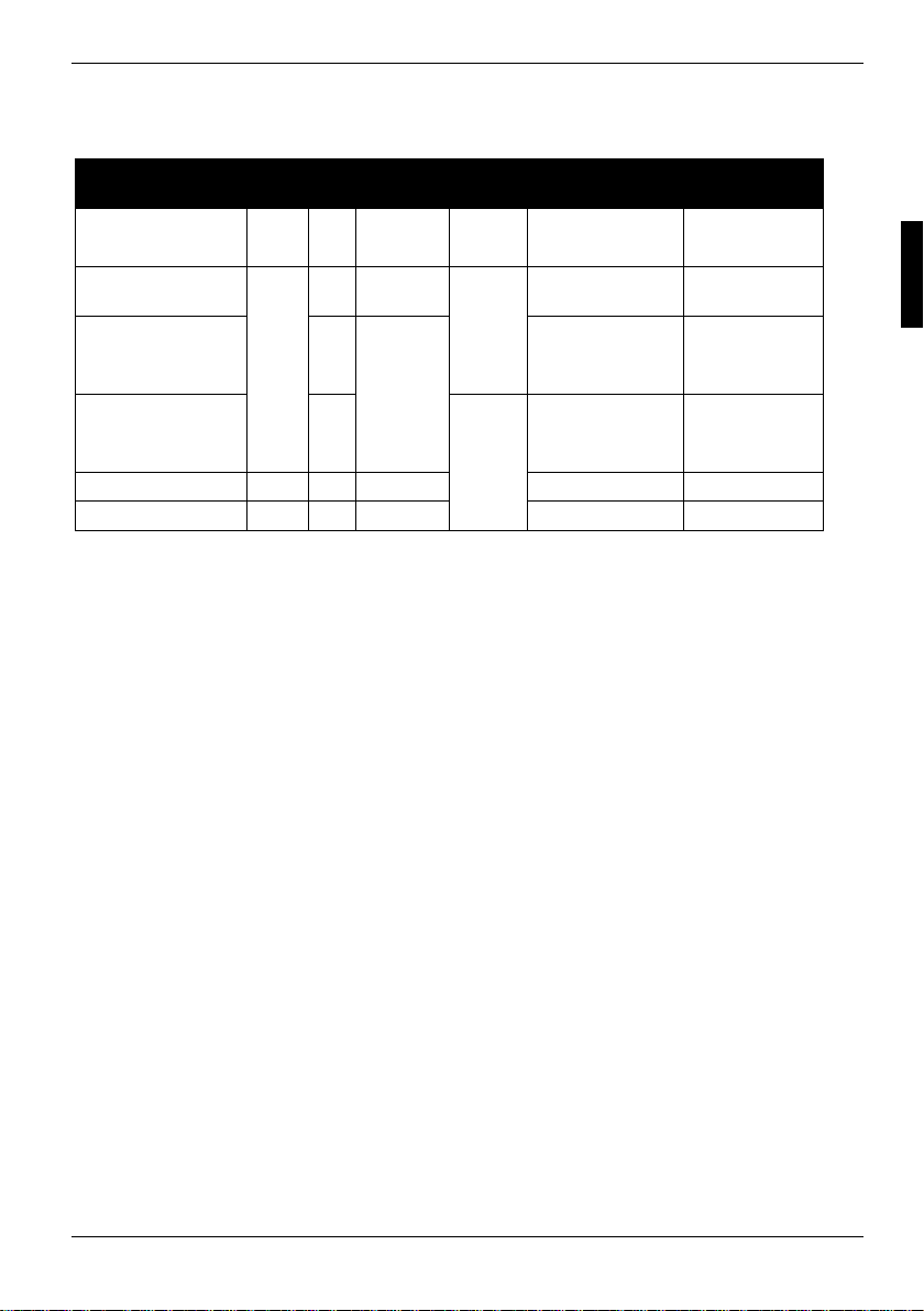
APM and ACPI system status, energy-saving modes
APM and ACPI system status, energy-saving modes
System status ACPI
Normal operation G0 S0 On On Normal
Simple energy-
saving mode
Maximum energy-
saving mode **
"Save to DRAM"
Maximum energy-
saving mode **
"Save To Disk"
“Soft Off" G2 S5 Soft Off Nearly zero Full boot time
Mechanically Off G3 Off
* G = Global status; S = System status
** The power supply unit must provi de sufficiently loadable 5 V standby voltage.
To use the WOL functionality the power supply must provide a 5 V auxiliary volt age (5V SB) of at
least 1 A.
Status*
G1
APM
Status
S1 Standby Almost like
S3
S4 Wake-up
Power
LED
flashin
g
Off
Power
consumption
normal
RAM,
wake-up
components
components
Zero Full boot time
Wake-up time
Almost
immediately
ca. 5s
ca. 20s
A26361-D1555-Z121-2-6319 English - 25
Page 77
Mainboard Revision and BIOS Version
Mainboard Revision and BIOS Version
The compatibility, e.g. with new proces sors, can be independent of the BIOS version or the revision
status of the mainboard used. The CP U and BIOS compatibility lists are available on the Internet at
www.fujitsu-siemens.de/mainboards.
Mainboard Revision
The revision status of the mainboard exactly identifies which mainboard you have. It is indicated on
a sticker on the edge of the m ai nboard:
D1555-C12 GS 1
05618476
Example Mainboard-Revision
BIOS version
The BIOS version can be displ ayed in the BIOS Setup.
Ê Press [F2] during booting to open the BIOS Setup.
Ê Press [F1].
The BIOS version is specified on the displayed information page under the entry BIOS Release.
26 - English A26361-D1555-Z121-2-6319
Page 78

Error messages
This chapter contains error messages generated by the mainboard.
Available CPUs do not support the same bus frequency - System halted!
Memory type mixing detected
Non Fujitsu Siemens Memory Module detected - Warranty void
There are more than 32 RDRAM devices in the system
Check whether the system configuration has changed. If necessary, correct the settings.
BIOS update for installed CPU failed
This message appears if the microcode update required for the connec t ed processor is not
contained in the system BIOS.
Ê Boot the system with the inserted Flash BIOS floppy disk.
Ê Abort the normal Flash BIOS update by answering the question about whether you want to
perform the update with
n Ú
Ê To carry out the Flash BIOS update for the proces sor, enter:
flashbioË/p6 Ú
Check date and time settings
The system date and time are invalid. Set the current date and time in t he Main menu of the
BIOS Setup.
CPU ID 0x failed
Switch the server off and on again. If the message is still displayed, go into the BIOS setup and
set the corresponding proces sor to Disabled in the Server - CPU Status menu; please contact
your sales outlet or customer service centre.
CPU mismatch detected
You have replaced the processor or changed the frequency setting. As a result, the
characteristic dat a of the processor have changed. Conf i rm this change by running the BIOS
Setup and exiting it again.
Diskette drive A error
Diskette drive B error
Check the entry for the diskette drive in the Main menu of t he BIOS Setup. Check the
connections to the dis kette drive.
A26361-D1555-Z121-2-6319 English - 27
Page 79

Error messages
DMA test failed
EISA CMOS not writable
Extended RAM Failed at offset: nnnn
Extended RAM Failed at address line: nnnn
Failing Bits: nnnn
Fail-Safe Timer NMI failed
Multiple-bit ECC error occurred
Memory decreased in size
Memory size found by POST differed from EISA CMOS
Single-bit ECC error occurred
Software NMI failed
System memory exceeds the CPU’s caching limit
System RAM Failed at offset: nnnn
Shadow RAM Failed at offset: nnnn
Switch the device off and on again. If the message is still displayed, pleas e contact your sales
outlet or customer serv i ce centre.
Failure Fixed Disk 0
Failure Fixed Disk 1
Fixed Disk Controller Failure
Check the entry for the hard disk drive in the Main menu and the entry for the IDE drive
controller in the Advanced - Peripheral Configuration menu of the BIOS Setup. Check the hard
disk drive's connec tions and jumpers.
Incorrect Drive A - run SETUP
Incorrect Drive B - run SETUP
Correct the entry for the diskette drive in the Main menu of t he BIOS Setup.
Invalid NVRAM media type
Switch the device off and on again. If the message is still displayed, pleas e contact your sales
outlet or customer serv i ce centre.
Invalid System Configuration Data
In the Advanced menu of the BIOS Setup set the entry Reset Configuration Data to Yes.
Invalid System Configuration Data - run configuration utility
Press F1 to resume, F2 to Setup
This error message may be displ ayed if the machine was swit ched off during system start-up.
Call BIOS Setup and switch to the Advanced menu. Select the menu item Reset Configuration
Data and change the sett i ng to Yes. Save the change and termi nate BIOS Setup. Reboot the
device.
Keyboard controller error
Connect another keyboard or another mouse. I f the message is still displayed, please contact
your sales outlet or customer service centre.
Keyboard error
Check that the keyboard is connected properly.
Keyboard error nn
nn Stuck Key
Release the key on the keyboard (nn i s the hexadecimal code for t he key).
28 - English A26361-D1555-Z121-2-6319
Page 80

Error messages
Missing or invalid NVRAM token
Switch the device off and on again. If the message is still displayed, pleas e contact your sales
outlet or customer serv i ce centre.
Monitor type does not match CMOS - RUN SETUP
Correct the entry for the moni tor type in the Main menu of the BIOS Setup.
On Board PCI VGA not configured for Bus Master
In the BIOS Setup, in the Advanced menu, submenu PCI Configuration, set the Shared PCI Master
Assignment entry to VGA.
One or more RDRAM devices are not used
One or more RDRAM devices have bad architecture/timing
One or more RDRAM devices are disabled
Contact your system administrator or contact our customer service centre.
Operating system not found
Check the entries for the hard di sk drive and the floppy dis k drive in the Main menu and the
entries for Boot Sequence submenu of the BIOS Setup.
Parity Check 1
Parity Check 2
Switch the device off and on again. If the message is still displayed, pleas e contact your sales
outlet or customer serv i ce centre.
Previous boot incomplete - Default configuration used
By pressing functi on key [F2] you can check and c orrect the settings in BIOS Setup. By
pressing function key [F 1] the system starts with incomplete system configuration. If the
message is still displayed, pleas e c ontact your sales outlet or customer service centre.
Real time clock error
Call the BIOS Setup and enter the correct time in the Main menu. I f the message is sti l l
displayed, please contact your sales outlet or customer service centre.
Service Processor not properly installed
The server management controller has not been correctly inst al l ed. If the message is s till
displayed, please contact your sales outlet or customer service centre.
Storage Extension Group = xy
Configuration error, x Storage Extensions(s) found, configured are y
SE(s).
Device List: k1, k2 ...
The specified number of storage expansion units (SEs) in the BIOS Setup menu Server - Storage
Extensions - Number of connected SE is incorrect. Check how many SEs within the group are
connected at the server and c hange the setting in BIOS Setup. Check whet her you have
assigned the same devic e I D twice.
xy = Group number
x = Number of SEs found on the c om m uni cation bus
y = Number of SEs entered in Number of connected SE
k1, k2 ... = Device ID of the storage extensions found
A26361-D1555-Z121-2-6319 English - 29
Page 81

Error messages
System battery is dead - Replace and run SETUP
Replace the lithium battery on the mainboard and redo the settings i n the BIOS Setup.
System Cache Error - Cache disabled
Switch the device off and on again. If the message is still displayed, pleas e contact your sales
outlet or customer serv i ce centre.
System CMOS checksum bad - - Default configuration used
Call the BIOS Setup and correct the previously made entries or set the default entries .
System Management Configuration changed or Problem occurred
A system fan or system sensor has failed. Check the hardware operation.
System timer error
Switch the device off and on again. If the message is still displayed, pleas e contact your sales
outlet or customer serv i ce centre.
Uncorrectable ECC DRAM error
DRAM Parity error
Unknown PCI error
Switch the device off and on again. If the message is still displayed, pleas e contact your sales
outlet or customer serv i ce centre.
Verify CPU frequency selection in Setup
The frequency setting for t he processor is invalid. Correct the BIOS Setup and the setting.
30 - English A26361-D1555-Z121-2-6319
Page 82

Glossary
The technical terms and abbrevi ations given below represent only a selection of the full li st of
common technical term s and abbreviations.
Not all technical terms and abbreviations list ed here are valid for the described mainboard.
ACPI Advanced Configurati on and
Power Management Interface
AC'97 Audio Codec '97 IPSEC Internet Protocol Security
AGP Accelerated Graphics P ort ISA Industrial Standard Architecture
AMR Audio Modem Riser LAN Local A rea Net work
AOL Alert On LAN LSA LAN Desk Service Agent
APM Advanc ed Power Management MCH Memory Controller Hub
ASF Alert S tandard Format MMX MultiMedia eXtension
ATA Advanc ed Technology
Attachment
BIOS Basic Input Output System PCI Peripheral Component
BMC Baseboard management
controller
CAN Controller Area Network PXE Preboot eXecut i on Environment
CPU Central Processing Unit RAM Random Access Memory
CNR Communication Network Riser RAMDAC Random Access Memory Digi tal
C-RIMM Continuity Rambus Inline
Memory Module
DIMM Dual Inline Memory Module RIMM Ram bus Inline Memory Module
ECC Error Correcting Code RTC Real Time Clock
EEPROM Electrical Erasable
Programmable Read Only
Memory
FDC Floppy disk controller SDRAM Synchronous Dynamic Random
FIFO Firs t -In First-Out SGRAM Synchronous Graphic Random
FSB Front Side B us SIMD Streaming Mode I nstruction
FWH Fi rm ware Hub SMBus System Management Bus
GMCH Graphics and M em ory Controller
Hub
GPA Graphics Performance
Accelerator
I2C Inter Integrated Circuit VGA Video Graphic A dapter
IAPC Instantly A vailable Power
Managed Desktop PC Design
ICH I/O Controller Hub
IDE Intelligent Drive Electronics
P64H PCI64 Hub
Interconnect
PSB Processor System Bus
Analogue Converter
RDRAM Rambus Dynamic Random
Access Memory
SB Soundblaster
Access Memory
Access Memory
(Single Instruction Multiple Data)
SVGA Super Video Graphic Adapter
USB Univers al Serial Bus
WOL Wak e On LA N
A26361-D1555-Z121-2-6319 English - 31
Page 83

Sommaire
Mainboard D1555................................................................................................................................ 1
Symboles...................................................................................................................................... 1
Remarques importantes ....................................................................................................................... 2
Remarques relatives aux cartes................................................................................................... 2
Aperçu des caractéristiques ................................................................................................................. 3
Caractéristiques ........................................................................................................................... 4
Notice succincte Monter la carte mère ................................................................................................. 5
Avant le montage ......................................................................................................................... 5
Ports et connecteurs.......................................................................................................................... 7
Ports externes ...................................................................................................................................... 7
Port LAN....................................................................................................................................... 7
Fonction audio à 2, 4 ou 6 canaux ...............................................................................................7
Ports internes et connecteurs............................................................................................................... 9
Port pour disques durs ................................................................................................................. 9
Affectation des broches des ports internes .......................................................................................... 9
Réglages avec interrupteurs et cavaliers....................................................................................... 13
Extensions / mises à niveau............................................................................................................ 14
Remplacer le processeur.................................................................................................................... 14
Monter/démonter le processeur ................................................................................................. 14
Etendre la mémoire vive..................................................................................................................... 16
Monter des cartes graphiques AGP ................................................................................................... 18
Monter des cartes PCI........................................................................................................................ 18
Interruptions de BUS PCI - Sélection du logement PCI adéquat ............................................... 18
Remplacer la pile au lithium ....................................................................................................... 20
BIOS - Actualisation ........................................................................................................................... 21
BIOS-Recovery - Restaurer le BIOS système.................................................................................... 22
Mise à jour du microcode ................................................................................................................... 22
Pilotes................................................................................................................................................. 23
Annexe............................................................................................................................................... 24
Propriétés électriques......................................................................................................................... 24
Etat du système APM et ACPI, modes d’économie d’énergie............................................................ 25
Révision de la carte mère et version du BIOS.................................................................................... 26
Messages d’erreur............................................................................................................................ 27
Glossaire ............................................................................................................................................ 31
A26361-D1555-Z121-2-6319
Page 84

Page 85

Mainboard D1555
Votre carte mère est disponible en plusieurs niveaux d'équipement. Selon la configuration de votre
carte mère, il est possible que certains composants matériels ne soient pas présents, bien que
décrits dans le présent manuel.
Autres informations
Vous trouverez des informations sur le Setup du BIOS ainsi que des descriptions supplémentaires des
pilotes dans :
• les fichiers "Lisezmoi" sur votre disque dur
• les disquettes de pilotes existantes
• sur les CD "Drivers & Utilities Collection", "Drivers & Utilities" ou "ServerStart".
Symboles
Les symboles suivants sont utilisés dans ce manuel.
Ê signale une opération que vous devez exécuter.
Ë signifie que vous devez insérer un espace à cette position.
Ú signifie que vous devez actionner la touche Entrée.
Les textes en caractères machine correspondent à des affichages écran.
Les textes en caractères machine gras sont des textes que vous devez entrer au clavier.
Les caractères en italiques symbolisent des commandes ou des options de menu.
"Entre guillemets" sert à identifier des titres de chapitres et différents concepts à mettre en évidence.
Pour charger la documentation, le programme Acrobat Reader doit être installé. Le
programme est disponible dans le répertoire utls/acrobat. du CD-Rom.
i
Vous trouverez d'autres informations dans les fichiers lisezmoi.txt correspondants.
signale des remarques dont le non-respect peut nuire à votre santé ou entraîner des
dommages matériels.
!
désigne des informations et conseils complémentaires pour une utilisation adéquate du
système.
i
A26361-D1555-Z121-2-6319 Français - 1
Page 86

Remarques importantes
Remarques importantes
Si la carte mère est intégrée, vous devez ouvrir le système pour y accéder. La façon de démonter et
de remonter le système est décrite dans le manuel d’utilisation du système.
Les câbles de données vers les périphériques doivent disposer d’un blindage suffisant.
Veuillez respecter les consignes de sécurité indiquées dans le manuel d’utilisation du
système.
!
Un remplacement non conforme de la pile au lithium peut provoquer une explosion. Par
conséquent, lisez impérativement les informations reprises dans le chapitre "Extensions /
mises à niveau" - "Remplacer la pile au lithium".
En cours de fonctionnement, certains composants peuvent devenir très chauds. Veuillez
en tenir compte lors de toute extension de la carte mère. Le risque de brûlure est réel !
Remarques relatives aux cartes
Pour éviter d’endommager la carte mère ainsi que les éléments et circuits qu’elle comporte, montez
et démontez les cartes avec le plus grand soin et la plus grande prudence. Veillez à ce que les
cartes soient insérées verticalement, sans endommager de composants, de circuits ou d’autres
éléments (comme les contacts à ressort EMI p. ex.).
Retirez la fiche secteur de la prise de courant à terre de protection afin que le système et la carte
mère soient séparés de la tension du réseau.
Manipulez les mécanismes de verrouillage (taquet d’encastrement, boulons de centrage, etc.) avec
précaution lors du remplacement de la carte mère ou de composants (module mémoire ou
processeur, p. ex ;).
N'utilisez jamais d'objets pointus (tournevis) comme levier.
Tel qu’il est livré, cet carte est conforme à la directive CE 89/336/CEE "Compatibilité
électromagnétique".
La conformité a été testée dans une configuration typique de PC.
Lors du montage de la carte, il convient de respecter les consignes de montage
spécifiques qui figurent dans le manuel d’utilisation de l’appareil.
La garantie expire si vous endommagez le système en montant ou en remplaçant des
extensions. Pour obtenir des informations sur les extensions possibles, consultez notre
i
S.A.V. ou votre revendeur.
Les cartes constituées d'éléments à risque électrostatique (ESD = Electrostatic
Sensitive Devices) sont signalées par l'étiquette ci-contre :
Si vous manipulez des cartes constituées d’éléments à risque électrostatique, vous
devez impérativement respecter les consignes suivantes :
• Vous devez vous décharger de l'électricité statique (en touchant un objet relié à
la terre, par exemple) avant de manipuler les cartes.
• Les outils et les machines utilisés doivent être dépourvues d'électricité statique.
• Débranchez les câbles avant de connecter ou de déconnecter les cartes.
• Manipulez les cartes en les tenant uniquement par leurs bords.
• Evitez de toucher les broches ou les circuits d'une carte.
2 - Français A26361-D1555-Z121-2-6319
Page 87

Aperçu des caractéristiques
Aperçu des caractéristiques
Caractéristiques embarquées D1555-C
Chipset SiS 648 / 963
Format ATX
VGA -
Audio / 6 canaux / S/PDIF 5.1 / /
Vibreur sonore / Port haut-parleur intégré / -
LAN / avec Alert-on-LAN / -
RAID -
FireWireTM
HI-SPEED USB 2.0
Port pour lecteur SmartCard (USB / série) - / -
Surveillance de la température -
Surveillance du système -
Support pour le clavier Fujitsu Siemens Computers avec touche
de mise sous tension
Ports internes
Logements pour modules DIMM (DDR 333 SDRAM / DDR 266
SDRAM )
Port AGP (4/8x, 32 bits, 66 MHz, 1,5 V) 1
Port PCI (32 bits, 33 MHz, 5 V et 3,3 V) 5
Port CNR (type A, AC‘97 uniquement) 1
Interface IDE RAID (RAID 1,2 / IDE 3,4) -
Canal IDE (Ultra DMA/133) 2
Interface lecteur de disquettes (jusqu’à 2,88 Mo) 1
S/PDIF* (audio numérique) -
CD / AUX entrée audio 1 / 1
Panneau de commande audio (écouteurs, microphone) 1
Wake on LAN -
Connecteur* IEEE 1394 (FireWireTM) 1
Ports USB* (2.0, ~480 MB/s) 2 ou 4
Ports série* (FIFO, compatible 16550) -
Ports pour ventilateurs PSU** / CPU / AUX1 / AUX2 - / 1 / 1 / -
Port SMBus* (température du boîtier) -
Surveillance du boîtier* (boîtier ouvert) -
Alimentation électrique ATX / ATX12V / AGP PRO 1 / 1 / -
-
2 / 3
A26361-D1555-Z121-2-6319 Français - 3
Page 88

Aperçu des caractéristiques
Ports externes
VGA -
Audio Mic In / Line in / Line out
ou arrière / frontal / central, bas (via pilote)
Game/MIDI -
S/PDIF 5.1 (Cinch) 1
LAN (RJ-45) 1
PS/2 souris/clavier 1 / 1
Port 1394 (FireWire) 1
Ports USB (2.0, ~480 MB/s) 4
Connexions série (FIFO, compatible 16550) 1
Connexion parallèle (EPP/ECP) 1
* utilisé pour des appareils internes ou en option via le panneau de commande
en face avant ou arrière
** n'est pas supporté par les alimentations standard
1 / 1 / 1
Caractéristiques
Votre carte mère est disponible en plusieurs niveaux d'équipement. Votre carte mère présente ou
supporte les caractéristiques décrites ci-après, en fonction de sa configuration.
DeskView / DeskViewOEM
Le logiciel de gestion DeskView/DeskViewOEM* compatible réseau se compose
essentiellement de trois modules :
• DeskInfo montre les principales données machines du PC dans un réseau (local
et/ ou sur le PC de l’administrateur).
• DeskAlert surveille le fonctionnement de tous les composants essentiels en
fonction du modèle de carte mère et déclenche des alarmes si nécessaire.
• DeskFlash exécute une mise à jour du BIOS sous Microsoft Windows.
Recovery BIOS
En cas d’erreur lors d’une mise à jour du BIOS (suite à une panne de courant, p. ex.),
le BIOS système est détruit. Toutes les cartes mères de Fujitsu Siemens Computers
disposent d’un ‘Recovery BIOS’. Le BIOS détruit peut ainsi être facilement restauré.
Vous trouverez des instructions précises dans le chapitre "BIOS-Recovery - Restaurer
le BIOS système".
IA-PC
Instantly Available PC assure une disponibilité rapide du PC à partir du mode
d’économie d’énergie. En quelques secondes, le PC réintègre exactement l’état dans
lequel il se trouvait au moment de la mise hors tension. Pas besoin de longues
procédures de démarrage. Lorsque des applications sont ouvertes, le PC peut
facilement basculer en mode d’économie d’énergie, selon le système d’exploitation. Il
suffit pour cela d’appuyer sur l’interrupteur Marche/Arrêt.
4 - Français A26361-D1555-Z121-2-6319
Page 89

Notice succincte Monter la carte mère
Si vous avez acheté la carte mère séparément, vous pouvez la monter sur votre système en suivant
les quelques instructions ci-dessous.
Les tâches décrites ci-après présupposent une connaissance élémentaire des PC et ne peuvent être
exécutées par des profanes. Si vous n’êtes pas sûr de posséder les connaissances requises,
confiez ces tâches à un spécialiste.
Les illustrations des systèmes montrent des exemples de boîtiers possibles.
Avant le montage
Ê Respectez les instructions données dans le chapitre "Remarques importantes".
Ê Vérifiez si le processeur, les modules d’extension mémoire et l’alimentation électrique
conviennent pour ce type de carte mère :
− Pour les processeurs, voir le chapitre "Remplacer le processeur".
− Pour les modules d’extension mémoire, voir le chapitre "Etendre la mémoire vive".
− Pour l’alimentation électrique, voir le chapitre "Propriétés électriques".
Ê Vérifiez si la consommation de courant des ventilateurs (processeur, boîtier) n'excède pas la
capacité de charge des ports ventilateurs (voir le chapitre "Propriétés électriques").
Ê Commencez par monter les composants absolument indispensables (carte graphique,
processeur et refroidisseur, module d’extension mémoire) et procédez uniquement aux
branchements nécessaires (bloc d’alimentation, raccordements de boîtier comme le
commutateur ATX, disque dur ou lecteur de disquettes). Les autres cartes et appareils ne
peuvent être montés qu’une fois que la configuration minimale a été démarrée avec succès
(voir le chapitre "Extensions / mises à niveau").
A26361-D1555-Z121-2-6319 Français - 5
Page 90

Notice succincte Monter la carte mère
Montage
Ê Dans la mesure du possible, équipez déjà la carte mère, avant son montage dans le boîtier,
d’un processeur, d’un refroidisseur et de modules d’extension mémoire. Vous trouverez
d'autres informations à ce sujet dans le chapitre "Remplacer le processeur".
Ê Ouvrez le boîtier en suivant les
instructions reprises dans le manuel
d’utilisation de votre système.
Ê Si aucun panneau de raccordement
approprié n’a été prévu dans le boîtier,
montez le panneau de raccordement (1)
compris dans la livraison.
Veillez à ce que le cache soit bien orienté de
manière à adapter les raccordements à la
carte mère par la suite.
Ê Présentez la carte mère par le côté
comportant le panneau de
raccordement (2) et insérez ensuite la
carte dans le boîtier (3).
Veillez à ce que tous les écarteurs du boîtier
soient en regard des orifices de montage de
la carte mère.
Ê Fixez la carte mère avec les vis livrées.
Ê Raccordez les câbles d’alimentation électrique, le panneau de commande et les lecteurs de
disquette aux différents ports de la carte mère.
Installation des pilotes
Ê Installez les pilotes destinés au jeu de composant (chipset). Ces pilotes sont disponibles sur le
CD "Drivers & Utilities" fourni. Pour l’installation des pilotes, voir le chapitre "Pilotes".
6 - Français A26361-D1555-Z121-2-6319
Page 91

Ports et connecteurs
Vous trouverez l’emplacement des ports et des connecteurs sur la page "Couverture/Cover".
Les composants et connecteurs marqués ne doivent pas être disponibles sur la carte mère.
Ports externes
Vous trouverez l’emplacement des ports externes sur la page "Couverture/Cover".
LAN
* L’activation de la fonction audio 6 canaux est assurée par un pilote.
Port clavier PS/2, violet
Interface série, turquoise
Port LAN
Sortie audio (Line out), vert clair
ou frontal*
Entrée audio (Line in), bleu ciel
ou central / bas*
1394
Port souris PS/2, vert
Port parallèle/imprimante, bordeaux
USB - Universal Serial Bus, noir
Prise microphone, rose
ou "surround"*
FireWire, gris
Port LAN
La carte mère est équipée d’un contrôleur LAN ADMtek AN983B. Ce contrôleur LAN supporte des
vitesses de transmission de 10 Mbits/s et 100 Mbits/s. Il dispose d’un tampon d’émission et de
réception de 2 Ko (FIFO) et supportent la fonctionnalité WOL via Magic Packet.
Le port LAN RJ45 comprend deux DEL (diodes électroluminescentes).
1 = Une liaison existe (vers un concentrateur,
2
1
p. ex.).
2 = Mode Link : la liaison LAN est active.
Mode WOL : réception d'un Magic
TM
Packet
.
Fonction audio à 2, 4 ou 6 canaux
La carte mère supporte une sortie audio à 6 canaux (2 canaux frontaux, 2 canaux arrières, 1 canal
central et 1 canal subwoofer). Vous pouvez ainsi connecter 4 ou 6 haut-parleurs et obtenir un
meilleur effet de son enveloppant (effet "surround").
A26361-D1555-Z121-2-6319 Français - 7
Page 92

Ports externes
Pilotes
Pour utiliser la fonction audio à 2, 4 ou 6 canaux, un pilote approprié doit être installé. Si le pilote
n’est pas encore installé, procédez comme décrit au chapitre "Extensions / mises à niveau", section
"Pilotes".
Raccorder des haut-parleurs
Le nombre de haut-parleurs connectés doit correspondre au nombre de canaux audio que vous
sélectionnez dans le logiciel du pilote.
Utiliser des ports audio externes
Sortie audio analogique à 2 canaux
1
2
3
1
2
3
1
2
3
Suivant la version du pilote et le système d'exploitation, les fonctions présentées ci-dessus
peuvent être différentes. Vous trouverez d'autres informations, le cas échéant, dans l'aide
i
respective des pilotes et du logiciel.
La configuration à 2 canaux propose les
fonctions Line-Out, Line-In et MIC.
1 = Line-In (bleu)
2 = Line-Out (canaux frontaux, vert)
3 = MIC (rouge)
Sortie audio analogique à 4 canaux
Dans la configuration à 4 canaux, la fonction
Line-In est transformée en fonction Rear-Out.
1 = Line-In (canaux arrière, bleu)
2 = Line-Out (canaux frontaux, vert)
3 = MIC (rouge)
Sortie audio analogique à 6 canaux
Dans la configuration à 6 canaux, les fonctions
Line-In et MIC sont transformées en fonction
Line-Out.
1 = Line-In (canaux arrière, bleu)
2 = Line-Out (canaux frontaux, vert)
3 = MIC (canal central et subwoofer, rouge)
Sélectionner les réglages pour la fonction audio à 2, 4 ou 6 canaux
Selon le pilote utilisé pour la fonction audio et en fonction du système d’exploitation, vous pouvez
configurer les propriétés audio, p. ex. sous Windows 2000 dans Démarrer - Paramètres - Panneau de
configuration – Sons et Multimédia.
8 - Français A26361-D1555-Z121-2-6319
Page 93

Ports internes et connecteurs
Ports internes et connecteurs
Vous trouverez l’emplacement des ports internes et des connecteurs sur la page
"Couverture/Cover". Vous trouverez ici des informations supplémentaires sur certains ports.
Port pour disques durs
Les disques durs Ultra-ATA/66, Ultra-ATA/100 ou Ultra-ATA/133 doivent être raccordés à l’aide d’un
câble spécialement prévu pour l’utilisation de disques durs Ultra-ATA/66, Ultra-ATA/100 ou UltraATA/133.
Ê Raccordez l’extrémité du câble pourvue d’une marque bleue à la carte mère.
Affectation des broches des ports internes
Vous trouverez ci-dessous l’affectation des broches de quelques ports internes, en français et/ou
anglais.
Certains ports décrits peuvent être optionnels !
i
Panneau de commande / Front panel
Respectez la polarité des DEL. Dans le cas de câbles
de raccordement, le pôle positif est souvent désigné
par un câble de couleur.
Ports Remarque
Reset
Power On/Off
HD LED
Power On LED Indique l’état du système APM ou ACPI (voir le chapitre "Etat du système APM et
ACPI, modes d’économie d’énergie").
Power On/Off
1)
Reset
HD-LED
1)
Power On
1) 3)
LED
1
2
Audio S/PDIF
Code
Signal
1
PIN
1 VCC
2 SPDIF out
3 GND
A26361-D1555-Z121-2-6319 Français - 9
Page 94

Affectation des broches des ports internes
AUX-Audio in
1
Code
PIN
1 Left AUX audio input
2 Analog GND
3 Analog GND
4 Right AUX audio input
Signal
CD-Rom Audio in
1
Code
PIN
1 Left CD audio input
2 CD GND
3 CD GND
4 Right CD audio input
Panneau de commande audio / Audio
Signal
1 2
front panel
Code PIN Signal Code PIN Signal
1 Micro input 2 Analog GND
3 Micro bias 4 Analog VCC
5 Right line output 6 Right line return
7 Not connected 8 Key
9 Left line output 10 Left line return
Si le panneau de commande audio n’est pas utilisé, vous devez mettre des cavaliers sur les paires
de broches 5/6 et 9/10.
10 - Français A26361-D1555-Z121-2-6319
Page 95

Affectation des broches des ports internes
FireWire (IEEE 1394)
1
Code PIN Signal Code PIN Signal
1 TPA+ 2 TPA-
3 GND 4 GND
5 TPB+ 6 TPB-
7 +12 V 8 +12 V
9 Key 10 GND
USB C/D - dual channel
1 2
E/F - dual channel
(internal or external via special cable)
Code PIN Signal Code PIN Signal
1 VCC C 2 VCC D
3 Data negative C 4 Data negative D
5 Data positive C 6 Data positive D
7 GND 8 GND
9 Key 10 Not connected
Ventilateur 1 / Fan 1
1
(processor fan - only for 3 pin fans)
Code
Signal
PIN
1 GND
2 Fix Fan voltage (+12 V, max. 1 A)
3 Fan sense
A26361-D1555-Z121-2-6319 Français - 11
Page 96

Affectation des broches des ports internes
Ventilateur 2 / Fan 2
(processor fan - only for 3 pin fans)
Code
PIN
1 GND
2 Fix Fan voltage (+12 V, max. 1 A)
3 Fan sense
Signal
Alimentation électrique ATX /
1
1
Power supply ATX
11
Code PIN Signal Code PIN Signal
1 +3.3V(P2V2P) 11 +3.3V(P2V2P)
2 +3.3V(P2V2P) 12 +12V (P12VP)
3 GND 13 GND
4 +5V (VCC) 14 PS on (low asserted)
5 GND 15 GND
6 +5V (VCC) 16 GND
7 GND 17 GND
8 Powergood (high asserted) 18 -5V (5PVN)
9 +5V Auxiliary (VCC Aux) 19 +5V (VCC)
Bloc d’alimentation ATX12 V /
10 +12V (P12VP) 20 +5V (VCC)
13
Power supply ATX 12 V
Code
PIN
1 GND 2 GND
3 +12 V 4 +12 V
Signal Code
PIN
Signal
12 - Français A26361-D1555-Z121-2-6319
Page 97

Réglages avec interrupteurs et cavaliers
Votre carte mère est équipée des interrupteurs ou des cavaliers. L’emplacement des interrupteurs ou
des cavaliers est indiqué sur la page "Couverture/Cover".
ON
1234
21
La cadence d'horloge du processeur est réglée automatiquement.
i
Utiliser le mot de passe du système et du Setup du BIOS - interrupteur 1 / paire de broches 1
L’interrupteur 1 / paire de broches 1 permet l’utilisation du mot de passe du système et du Setup du
BIOS.
On Lors de la mise en service de l’appareil, le mot de passe du système et du Setup du
Off Le mot de passe du système et du Setup du BIOS doit être introduit lors de la mise
BIOS est court-circuité et peut être modifié.
sous tension de l’appareil.
Interrupteur 1 = Utiliser le mot de passe du
système et du Setup du BIOS
Interrupteur 2 = restaurer le BIOS système
Interrupteur 3 = toujours régler sur off
Interrupteur 4 = toujours régler sur off
Paire de broches 1 est enfichée =
Utiliser le mot de passe du système et du Setup
du BIOS
Paire de broches 2 est enfichée =
restaurer le BIOS système
Tout autre réglage =
configuration usine; le cavalier n'a aucune
fonction
Restaurer le BIOS système - interrupteur 2 / paire de broches 2
L’interrupteur 2 / paire de broches 2 permet de restaurer le BIOS système après une mise à niveau
incorrecte. Pour restaurer le BIOS système, vous avez besoin d’une "disquette Flash-BIOS" (voir le
chapitre "BIOS - Actualisation").
On Le BIOS système démarre à partir du lecteur de disquettes A: et la disquette de BIOS
Off Fonctionnement normal (réglage standard).
Réservés - interrupteurs 3 et 4 (si disponibles)
Les interrupteurs 3 et 4 sont réservés. L’emplacement des interrupteurs n’a aucune importance.
A26361-D1555-Z121-2-6319 Français - 13
Flash introduite écrase le BIOS système sur la carte mère.
Page 98

Extensions / mises à niveau
Avant de procéder aux différentes manipulations décrites dans ce manuel, quittez le mode
d'économie d'énergie, mettez l’appareil hors tension et retirez la fiche secteur de la prise
!
avec terre de protection !
Même après l’avoir arrêté normalement, certaines parties de l’appareil (p. ex. modules
d’extension mémoire, cartes d’extension AGP et PCI) sont encore sous tension.
Remplacer le processeur
Caractéristiques techniques
• Pentium 4 avec processeur bus système à 400/533 MHz (PSB) dans un socket mPGA478
• Celeron avec processeur bus système à 400 MHz dans un socket mPGA478
Vous trouverez une liste actualisée des processeurs supportés par cette carte mère sur Internet à
l'adresse suivante : www.fujitsu-siemens.com/mainboards.
Monter/démonter le processeur
Ê Retirez le ventilateur éventuel ainsi que le refroidisseur.
2
2
3
3
1
1
Ê Soulevez le levier dans le sens de la flèche (1) et relevez-le jusqu’à la butée (2).
Ê Retirez l’ancien processeur de son logement (3).
Ê Placez le nouveau processeur dans son logement de telle manière que le coin biseauté du
processeur coïncide (4) avec le motif formé par les perforations du logement (A).
Ê Rabaissez le levier vers le bas jusqu’à l’entendre s’encastrer (5).
14 - Français A26361-D1555-Z121-2-6319
L'angle biseauté du processeur peut également être situé à un autre endroit que celui
indiqué sur le dessin.
i
4
4
5
5
A
A
Page 99

Remplacer le processeur
Montage du refroidisseur
Utilisez impérativement un matériau conducteur de chaleur entre le processeur et le refroidisseur. Si
un film (en caoutchouc) conducteur de chaleur a déjà été apposé sur le refroidisseur, utilisez-le. Si
ce n’est pas le cas, appliquez une très fine couche d’enduit conducteur de chaleur.
Vous ne pouvez utiliser les films conducteurs de chaleur qu’une seule fois. Si vous retirez le
refroidisseur, vous devrez le nettoyer et appliquer un nouvelle couche d’enduit conducteur de
chaleur avant de le remonter.
Veuillez tenir compte du fait que les clips de fixation du refroidisseur nécessaires sur la carte mère
varient en fonction du type de refroidisseur utilisé.
Si une contre-plaque est montée sur la face inférieure de la carte mère, n’utilisez pas de
refroidisseurs de type "Intel Boxed". En effet, les clips de fixation du refroidisseur seraient
i
alors endommagés.
Si vous utilisez un refroidisseur "Intel Boxed", veillez à ce que la carte mère soit adaptée
en conséquence. Le kit d’adaptation est livré avec la carte mère ou est disponible
séparément.
Si aucune contre-plaque n’est montée, vous pouvez utiliser aussi bien des refroidisseurs
"Intel Boxed" que des refroidisseurs standard. Si vous utilisez un refroidisseur "Intel
Boxed", la carte mère fléchit en raison de la forte pression exercée par les clips de
fixation. Ce comportement est ainsi décrit en détail par Intel.
Ê Suivant le modèle, vous devez soit retirer un
film de protection du refroidisseur soit
enduire le refroidisseur d’une pâte
conductrice de chaleur avant de le remonter.
Ê Des clips de fixation du refroidisseur sont
compris dans la livraison suivant le type de
processeur.
Ê Si vous avez monté le ventilateur optionnel,
connectez la fiche du ventilateur au port
correspondant sur la carte mère.
A26361-D1555-Z121-2-6319 Français - 15
Page 100

Etendre la mémoire vive
Etendre la mémoire vive
Caractéristiques techniques
Technologie : Module DIMM DDR 266 ou DDR 333 sans tampon
Taille : 32 Mo jusqu'à 3 Go DDR 266 SDRAM
Tailles des modules : 32, 64, 128, 256, 512 ou 1024 Moctets par module
Vous trouverez une liste actualisée des modules d’extension mémoire recommandés pour cette
carte mère sur Internet à l’adresse suivante : www.fujitsu-siemens.com/mainboards.
Au moins un module d’extension mémoire doit être monté. Avec les modules DDR 266, il est
possible d’utiliser jusqu’à trois modules d’extension mémoire à deux faces. Avec les modules DDR
333, il est possible d’utiliser jusqu’à deux modules d’extension mémoire à deux faces, trois modules
d’extension mémoire à trois faces ou un module d’extension mémoire à deux faces avec deux
modules d’extension mémoire à une face.
Il est possible de combiner des modules d’extension mémoire de capacités différentes.
!
Cadence d’horloge de la mémoire
La cadence d’horloge de la mémoire est influencée par le jeu de composants (chipset) et le bus
système du processeur. Le tableau reprend la vitesse de la mémoire en fonction du processeur
système bus.
184 broches ; 2,5 V; 64 bits, non-CCE
32 Mo jusqu'à 2 Go DDR 333 SDRAM
Seules des modules d’extension mémoire 2,5 V sans tampon peuvent être utilisées. Les
modules équipés d’un tampon ne sont pas autorisés.
Les modules d’extension mémoire DDR-DIMM doivent être conformes aux normes
PC2100 ou PC2700.
Prozesseur bus système
(MHz)
533 333 266
400 333 266
16 - Français A26361-D1555-Z121-2-6319
DDR333 (MHz) DDR266 (MHz)
 Loading...