

Page 1

Mainboard Deutsch, English, Français,
Short Description
Türkçe, Русский
Mainboard D2581/D2584
Page 2

Sie haben...
...technische Fragen oder Probleme?
Wenden Sie sich bitte an:
• Ihren zuständigen Vertriebspartner oder Ihre Verkaufsstelle
• unsere Hotline über das Kontaktformular unter
"
http://www.fujitsu-siemens.com/ support/contact/contact.html" oder für Kunden,
die ein einzelnes Mainboard gekauft haben: +49(0) 180 3777 005
Aktuelle Informationen und Updates (z. B. BIOS-Upd ate) zu unseren Mainboards finden
Sie im Internet: "
http://www.fujitsu-siemens.com/ mainboards"
Are there...
...any technical problems or other questions you need clarified?
Please contact:
• your sales partner or your sales outlet
• our hotline via the contact form at "
www.fujitsu-siemens.com/support/contact/contact.html" ,
or for customers who have purchased an individual mainboard: +49(0) 180 3777 005
The latest information and updates (e.g. BIOS update) on our mainboards can be
found on the Internet at: "
www.fujitsu-siemens.com/mainboards"
Page 3

Copyright © Fujitsu Siemens Computers GmbH 2007
Intel, Pentium and Celeron are registered trademarks of Intel Corporation, USA.
Microsoft, MS, MS-Dos and Windows are registered trademarks of Microsoft Corporation.
PS/2 and OS/2 Warp are registered trademarks of International Business machines, Inc.
All other trademarks referenced are t rademarks of their respective owners,
whose protected rights are ackn owledged.
All rights, including rights of translation, reproduction by printing, copying or
similar methods, even of parts are reserved.
Offenders will be liable for damages.
All rights, including rights created by patent grant o r registration of a utility model or
design, are reserved. Delivery subject to availability.
Right of technical modification reserved.
Page 4

Dieses Handbuch wurde erstellt von/This manual was produced by Xerox Global Services
Herausgegeben von/Published by Fujitsu Siemens Computers GmbH
AG 07/07
Ausgabe/Edition 1
A26361-D2581-Z110-1-8N19
*A26361-D2581-Z110-1-8N19*
Page 5
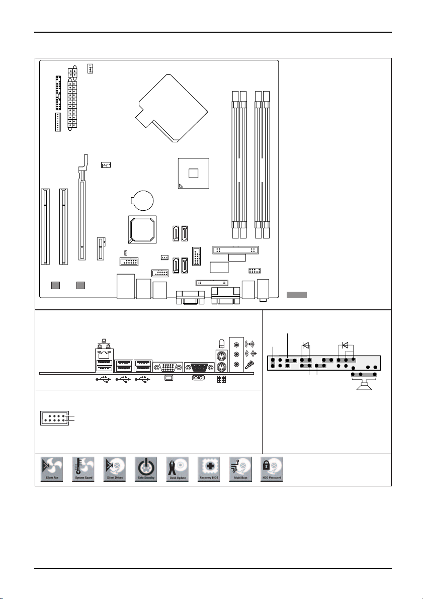
Mainboard D2581/D2584 - Internal co
Fan 2
Power supply 2
Frontpanel
Power supply 1
Power supply
FAN control
Fan 1
Battery
PCI e x 16
Intrusion
TPM Enable
PCI e x1
PCI2
Intel-LAN
PCI1
BroadcomLAN
USB 3+4
USB 5+6
nnectors and slots
SATA
10
USB
Floppy Connector
1+2
SATA
45
Parallel port
Super
I/O
SPDIF
1
3
Channel A
PS2
2
Audio
Frontpanel
4
Channel B
Audio
optional
External connectors rear Front panel
Power On/Off
Reset
USB dual channel
1
2
1 = VCC C
2 = VCC D
3 = Data negative C
4 = Data negative D
5 = Data positive C
6 = Data positive D
7 = GND
8 = GND
9 = Key
10 = Not connected
1) Both connector positions possible
2) 2pin or 3pin connector possible
Recovery inserted = The system starts
from floppy and allows a BIOS recovery
Password inserted = System- and BIOS
Password are skipped when device is
switched on
A26361-D2581-Z110-1-8N19, edition 1
1)
HD-LED
Power On LED
Recovery Password
Speaker
A26361-D2581-Z140-1-7619
2)
1
2
Page 6
Mainboard D2581/D2584
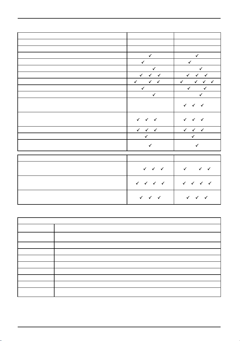
List of onboard Features D2581 D2584
Chipset
Board size
Intel® iQ33 Intel® iQ35
µBTX µBTX
VGA
Audio / 8-channel / S/PDIF /-/- /-/-
Buzzer / int. Speaker Support
-/
-/
LAN 1 Gbit / 100 Mb it/ 10 Mbit / / / /
LAN ASF / Aol / WoL / Boot /iAMT /-/ / /- /-/ / /
Serial ATA / ATA / RAID /-/- /-/
FireWireTM / USB 2.0 - / -/
FAN monitored PSU* / CPU FAN(1) / AUX1 (FAN2) /
AUX2 (FAN3)
FAN controlled PSU* / CPU FAN(1) / AUX1 (FAN2) /
AUX2 (FAN3)
-/-/-/-
/ / /- / / /-
/ / /-
TEMP monitored CPU / ONB1 / ONB2 / HDD / / /- / / /SmartCard SystemLock (USB / serial)
/- /-
Fujitsu Siemens Computers Keyboard Power Button
Support
Special onboard features
Silent Fan / Silent Fan LT / System Guard / Silent
Drives
Recovery BIOS / Desk Update / Multi Boot / Safe
Standby
HDD Password / Logo Boot / Intel O n Screen
Branding
* not supported by standard Power Supplies
Special Features
Green Edition
Silent Fan
Halogen-free and lead-reduced product
Independent temperature related processor fan and system fan supervision
and control
System Guard View and adjust Silent Fan
Silent Drives
Noise reduction for optical and hard disk drives
Safe Standby Prevents data loss in S3 (Save-to-RAM)
Recovery BIOS Restores a corrupted BIOS
Desk Upda te
Multi Boot
HDD Passwort
Silent Fan LT
Simple driver update with DU CD
Comfortable boot from any boot device
Access protection for ATA5/ATAI5 disk drives
Independent tem peratu re related processor fan and system fan control
D2581 D2584
/ / /-/ /
-/
/ / / / / /
/ / / /
A26361-D2581-Z110-1-8N19, edition 1
Page 7
Kurzbeschreibung des Mainboards
Kurzbeschreibung des Mainboa
Hinweise zu den Baugruppen
Beachten Sie bei Baugruppen mit EGB unbedingt Folgendes:
• Sie müssen sich statisch entladen (z. B. durch Berühren eines geerdeten
Gegenstands), bevor Sie mit Baugruppen arbeiten.
• Verwendete Geräte und Werkzeuge müssen frei von statischer Aufladung sein.
• Ziehen Sie den Netzstecker, bevor Sie Baugruppen stecken oder ziehen.
• Fassen Sie die Baugruppen nur am Rand an.
• Berühren Sie keine Anschluss-Stifte oder Leiterbahnen auf der Baugruppe.
Eine Übersicht der Leistungsmerkmale finden Sie im Datenblatt.
Besondere Merkmale
Ihr Mainboard ist in verschieden en Ausbaustufen erhältlich. Abhängig von der Konfigurat ion
Ihres Mainboards besitzt oder unterstützt das Mainboard bestimmte Merkmale.
In diesem Handbuch finden Sie die wichtigsten Eigenschaften dieses Mainboards beschrieben.
Weitere Info rmationen zu Mainboards finden Sie im Handbuch "Basisinformationen Mainboard"
auf der CD "User Documentation" oder "OEM Mainboard" bzw. im Internet.
rds
Anschlüsse und Steckverbinder
Die Position der Anschlüsse und Steckverbinder Ihres Mainboards finden
Sie am Anfang des Handbuches.
Die markierten Komponenten und Steckverbin der müssen nicht auf
dem Mainboard vorhanden sein.
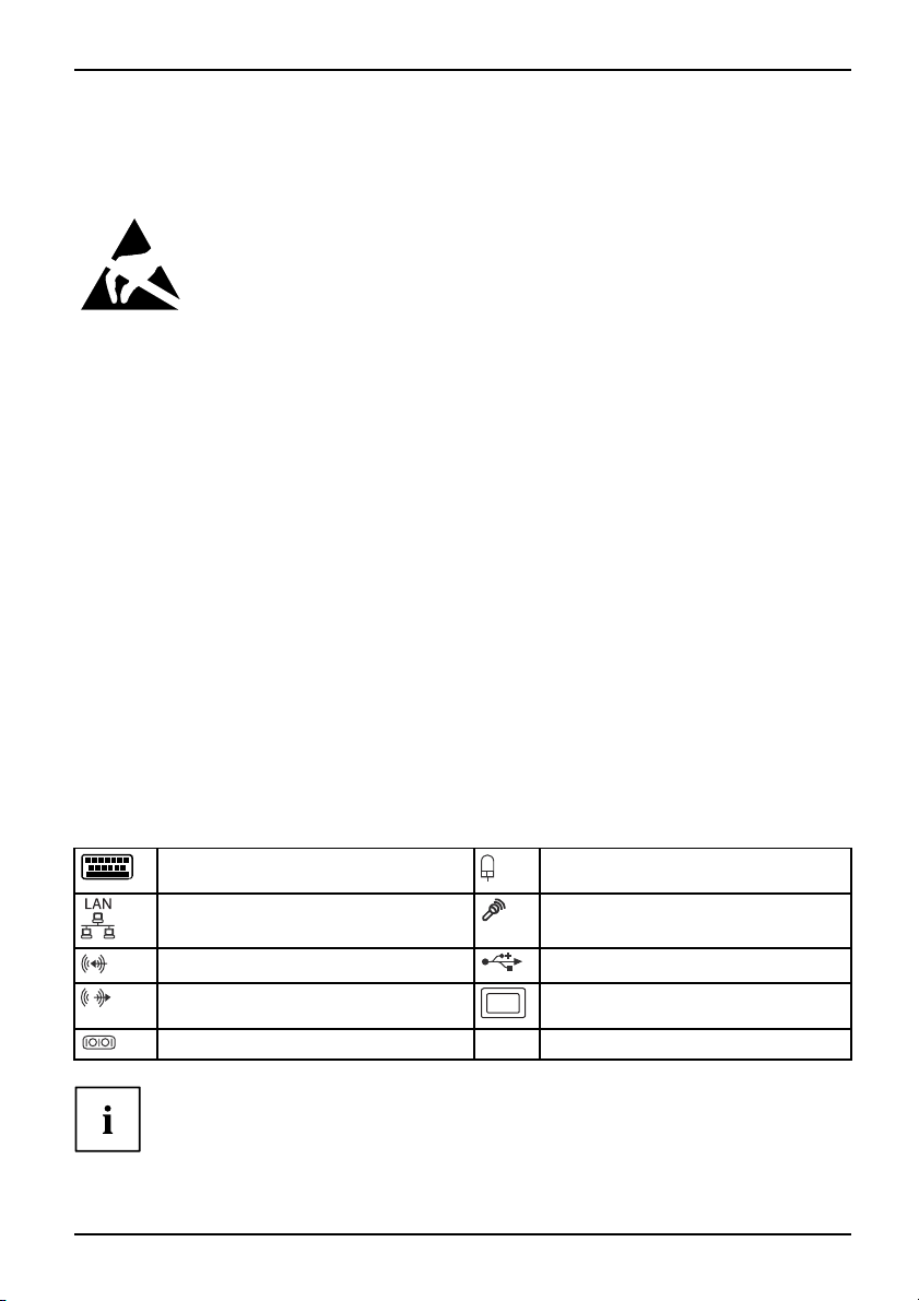
Externe Anschlüsse
Die Position der externen Anschlüsse Ihres Mainboards finden Sie am Anfang des Handbuches.
PS/2-Tastaturanschluss,
(optional)
LAN-Anschluss (RJ-45) Mikrofonanschluss, rosa
Audioeingang (Line in), h
Audioausgang (Line out), hellgrün VGA, blau
Serielle Schnittstelle, türkis
Die externen USB-Anschlüsse auf der Rückseite dürfen zusammen
bis max. 2 A belast et werden.
A26361-D2581-Z110-1-8N19, Ausgabe 1 Deutsch - 1
violett
ellblau
PS/2-Mausanschluss, grün
USB – Universal Serial Bus
(optional)
, schwarz
Page 8
Kurzbeschreibung des Mainboards
Grafikcontroller
• Intel GMA 3100
• 256 MByte Video Memory
• Unterstützung von ADD2 Karten (single und dual DVI Adapter Karte)
Auflösung (Farbtiefe bis zu 32 Bit/Pixel) Frequenz
1024 x 768 (empfohlen / max*) 120 / 200 Hz
1280 x 1024 (empfohlen / max*) 100 / 120 H z
1600 x 1200 (empfohlen / max*) 85 / 120 Hz
1440 x 900 Widescreen TFT (VGA / DVI) x / x
1680 x 1050 Widescreen TFT (VGA / DVI) x / x
1920 x 1200 Widescreen TFT (VGA / DVI) x / x
* maximale Bildwiederholrate für die Grafikeinstellung. Die Videoqualität kann
verzerrt ("deteriorated") sein, wenn die Maximaleinstellung verwendet wird.
Prozessor ein-/ausbauen
Für alle hier beschriebenen A
getrennt sein! Nähere Angab
rbeiten muss Ihr System vollständig von der Netzspannung
en dazu finden Sie in der Betriebsanleitung Ihres Systems.
Technische Daten
• Sockel LGA 775, max. 65W; Int
MHz FSB; Intel® Pentium Dua
Celeron® Processors 4xx 80
• Eine aktuelle Liste der von diesem Mainboard unt erstützten Prozessoren finden Sie
im Internet unter: "
www.fujitsu-siemens.com/mainboards".
el® Core 2 DUO Processors 1333/1066/800
l Core E 2xxx Processors 800 MHz FSB, Intel®
0MHzFSB
Fassen Sie auf keinen Fall die Unterseite des Prozessors an. Schon leichte
Verunreinigungen wie Fett von der Haut können die Funktion des Prozessors
beeinträchtigen oder den Prozessor zerstören. Setzen Sie den Prozessor mit
großer Sorgfalt in den Steckplatz, da die Fed e rkontakte des Steckplatzes sehr
empfindlich sind und nicht verbogen werden dürfen.
Sind ein oder mehrere Federkontakte verbogen, setzen Sie auf keinen Fall
den Prozessor ein, da dieser dadurch beschädigt werden könnte. Wenden
Sie sich bitte direkt an Ihren zuständigen Händler
2 - Deutsch A26361-D2581-Z110-1-8N19, Ausgabe 1
Page 9
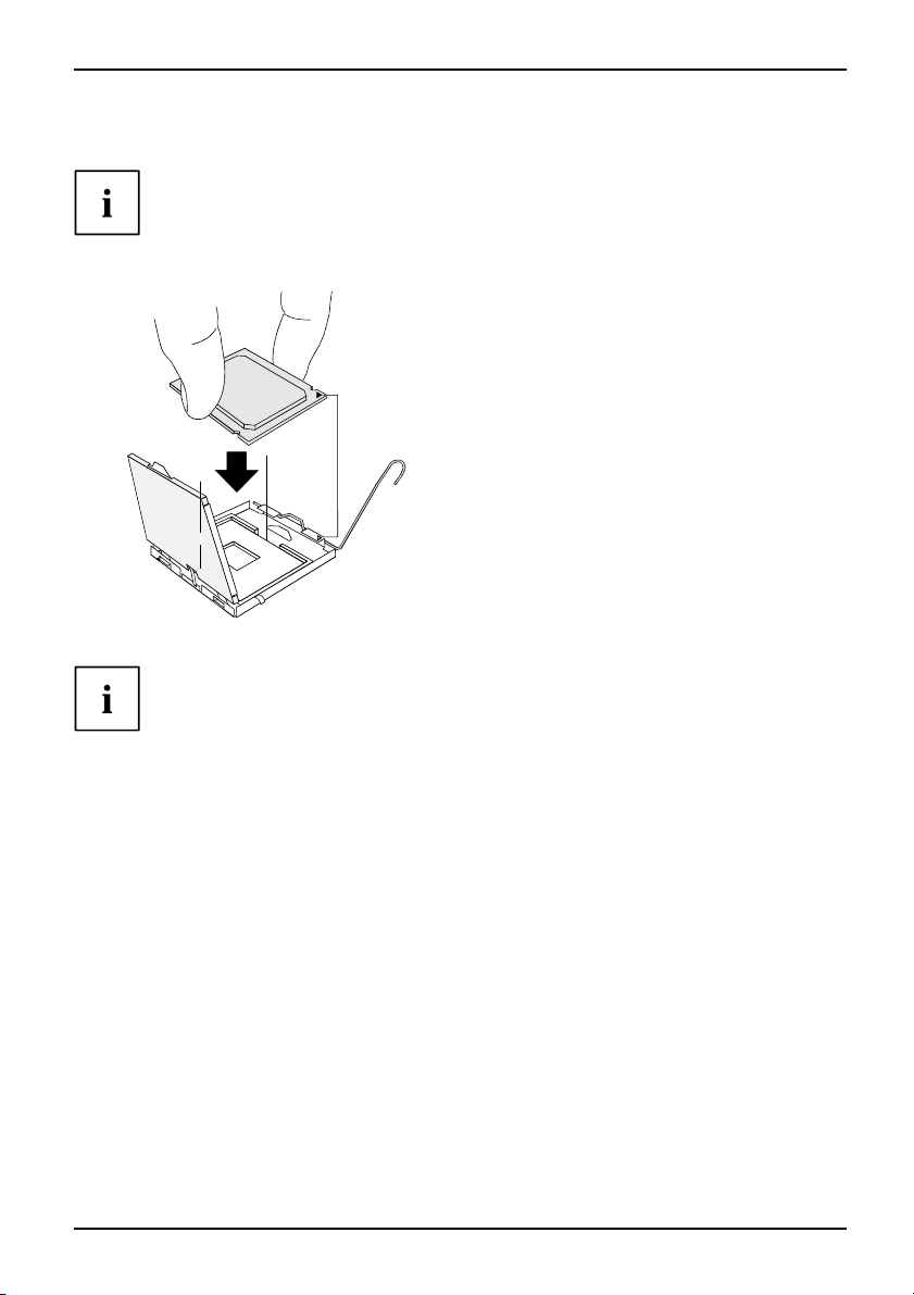
Vorgehensweise
Der Steckplatz für Prozessor ist zum Schutz der F ederkontakte mit einer Schutzkappe
abgedeckt. Im Garantiefall kann das Mainboard nur mit befestigter Schutzkappe
von Fujitsu Siemens Computers zurück genommen werden!
b
b
Kurzbeschreibung des Mainboards
► Entfernen Sie den Kühlkörper.
► Drücken Sie auf den Hebel und
haken Sie ihn aus.
► Klappen Sie die Halterung nach oben.
► Halten Sie den Prozessor mit Daumen
und Z eigefinger und stecken Sie ihn
so in den Steckplatz (b), dass die
Markierung des Prozessors mit der
a
Markierung am Steckplatz von der Lage
her übereinstimmt (a).
► Drücken Sie den Hebel nach unten,
bis er wieder einhakt.
► Entfernen Sie die Schutzklappe und
verwahren Sie diese.
Bitte beachten S
Kühlkörperhalt
► Je nach Ausbau-Variante m üssen Sie eine Schu tzfolie vom Kühlkörper abziehen oder den
Kühlkörper mit W ärmeleitpaste bestreichen, bevor Sie ihn aufsetzen.
► Befestigen Sie d
oder stecken Sie
A26361-D2581-Z110-1-8N19, Ausgabe 1 Deutsch - 3
ie, dass je nach verwendetem Kühlkörper unterschiedliche
erungen auf dem Mainboard benötigt werden.
en Kühlkörper - je nach Ausfüh rung - mit vier Schrauben
ihn in die Befestigungen.
Page 10
Kurzbeschreibung des Mainboards
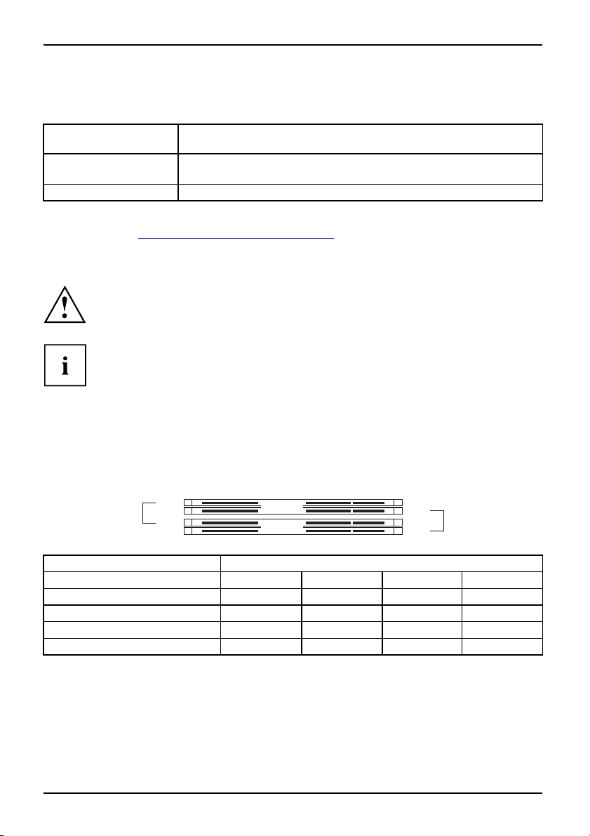
Hauptspeicher e in-/ausbauen
Technische Daten
Technologie
Gesamtgröße 128 MBytes bis 8 GB yte
DDR2 667 / 800 ungepufferte DIMM Module 240-Pin; 1,8 V; 64 Bit,
ohne ECC
Modulgröße
128, 256, 512, 1024 oder 2048 MByte pro Modul
Eine aktuelle Liste der für dieses Mainboard empfohlenen Speichermodule finden Sie
im Internet unter: "
www.fujitsu-siemens.com/mainboards".
Es muss mindestens ein Speichermodul eingebaut sein. Speichermodule mit
unterschiedlicher Speicherkapazität können kombiniert werden.
Es d ürfen nur ungepufferte 1,8 V-Speichermodule ohne ECC verwendet werden.
DDR2-Speichermodule müssen der PC2-5300U- oder PC2-6400U-Spezifikation
entsprechen.
Wenn Sie mehr als ein Speichermodul verwenden, dann achten Sie darauf,
die Speichermodule auf beide Speich erkanäle aufzuteilen. Dadurch nutzen
Sie d ie Performancevorteile des Dual-Channel-Mode.
Die maximale Systemperforman ce ist gegeben, wenn in Channel A und
Channel B die gleiche Speichergröße verwendet werden.
Um die Bestückung zu erleichtern, sind die Steckplätze (Slots) farbig gekennzeichnet.
Bei einer Speicherkonfiguration von 8 Gb yte kann der sichtbare und
benutzbare Hauptspeicher bis auf 7 Gbyte reduziert sein (abhängig
von der Konfiguration des Systems).
slot 4
slot 3
Channel B
Channel A
slot 2
slot 1
Anzahl der gesteckten Speichermodule
Zu verwendender Stec
Channel A, Slot 1
Channel B, Slot 2
Channel A, Slot 3
kplatz
1234
xxxx
xxx
xx
Channel B, Slot 4
x
Der Ein-/Ausbau ist im Handbuch "Basisinformationen Mainboard" beschrieben.
4 - Deutsch A26361-D2581-Z110-1-8N19, Ausgabe 1
Page 11
Kurzbeschreibung des Mainboards
PCI-Bus-Interrupts - Auswahl des richtigen PCI-Steckplatzes
Umfangreiche Informationen zu diesem Abschnitt finden Sie im Handbuch
"Basisinformationen Mainboard".
Um optimale Stabilität, Performance und Kompatibilität zu erreichen, vermeiden
Sie die mehrfache Nutzung von ISA IRQs oder PCI IRQ Lines (IRQ Sharing).
Sollte IRQ Sharing nicht zu umgehen sein, so müssen alle beteiligten Geräte
und deren Treiber IRQ Sharing unte rstützen.
Welche ISA IRQs den PCI IRQ Lines zugeordnet werden, wird normalerweise automatisch
vom BIOS festgelegt (siehe Beschreibung "BIOS-Setup").
Monofunktionale Erweiterungskarten
PCI-/PCI-Express-Erweiterungskarten benötigen maximal einen Interrupt, der als
PCI-Interrupt INT A bezeichnet wird. Erweiterungskarten, die keinen Interrupt benötigen,
können in einen beliebigen Steckplatz eingebaut werden.
Multifunktionale Erweiterungskarten od er Erweiterungskarten mit integrierter PCI-PCI Brigde
Diese Erweiterungskarten benötigen bis zu vier PCI-Interrupts: INT A, INT B, INT C, INT D.
Wie viele und welche dieser Interrupts verwendet werden, entnehmen Sie der
mitgelieferten Dokumentation der Karte.
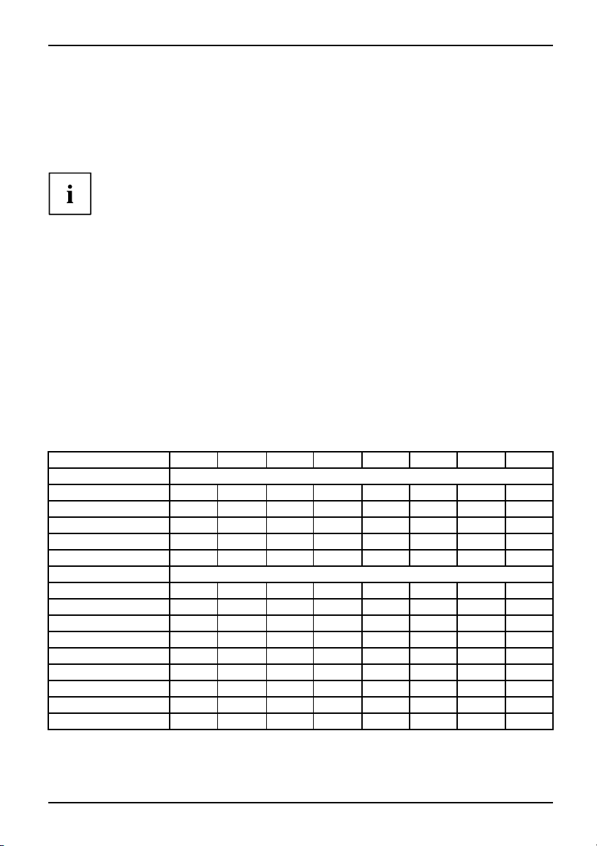
Die Zuordnung der PCI-Interrupts zu den IRQ Lines finden Sie in der folgend en Tabelle:
On board controller
PCI INT LINE
UHCI USB 1.1
Dev 1A Fn 0
Dev 1A Fn 1
Dev 1D Fn 0
Dev 1D Fn 1
Dev 1A Fn 2
EHCI USB 2.0
Dev 1A Fn 7
Dev 1D Fn 7
SATA #1
SATA #2
SMBus
Intel LAN
HD Audio
Broadcom LAN DAB
Onboard Graphik
1(A) 2(B) 3(C) 4(D) 5(E) 6(F) 7(G) 8(H)
1th
----
2nd
-
3rd
-------
4th
------
5th
-----
-
x
x
------
------
x
---
x
x
--
-------
---
-
x
------
---
--
x
x
x
-----
---C
x
-------
----
----
x
---
----
x
-
x
A26361-D2581-Z110-1-8N19, Ausgabe 1 Deutsch - 5
Page 12

Kurzbeschreibung des Mainboards
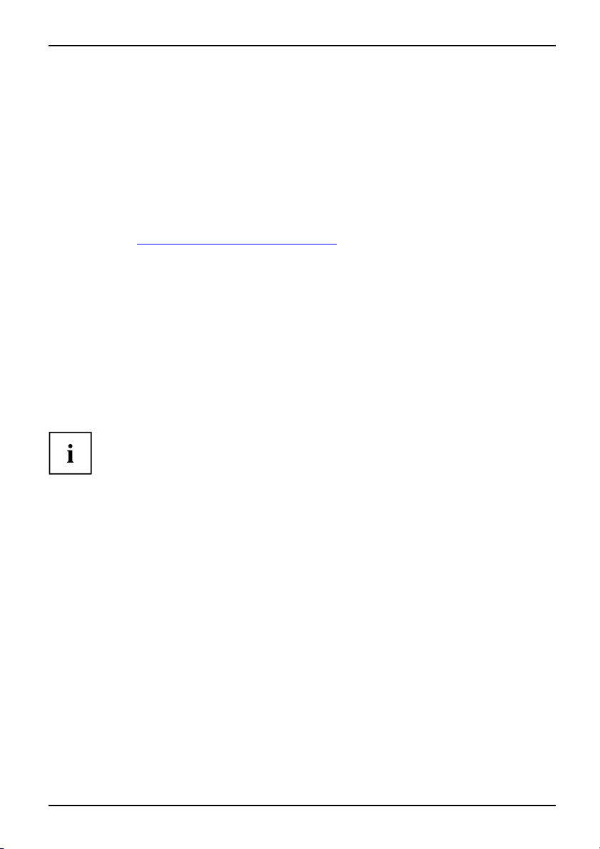
Mechanical Slot
PCI INT LINE
1(A) 2(B) 3(C) 4(D) 5(E) 6(F) 7(G) 8(H)
PCI
Slot 1
Slot 2
--
--
D
C
C
D
PCIe x16 ABCD
PCIe X1
------
-
-
BA
AB
---x
Verwenden Sie zuerst PCI-/PC I-Express-Steckplätze, die über eine einzige P CI IRQ Line
verfügen (kein IRQ Sharing). Wenn Sie einen anderen PCI-/PCI-Express-Steckplatz mit IRQ
Sharing benutzen müssen, überprüfen Sie, ob die Erweiterungskarte IRQ Sharing mit den
anderen Geräten auf dieser PCI IRQ Line einwandfrei unterstützt. Auch die Treiber aller Karten
und Komponenten an dieser PCI IRQ L ine müssen IRQ Sharing unterstützen.
-
-
-
6 - Deutsch A26361-D2581-Z110-1-8N19, Ausgabe 1
Page 13
Kurzbeschreibung des Mainboards
BIOS-Update
Wann sollte ein BIOS-Update durchgeführt werden?
Fujitsu Siemens Computers stellt neue BIOS-Versionen zur Verfügung, um die Kompatibilität
zu neuen Betriebssystemen, zu neuer Software oder zu neuer Hardware zu gewährleisten.
Außerdem können neue BIO S -Fu nktionen integriert werden.
Ein BIOS-Update sollte auch immer dann durchgeführt werden, wenn ein Problem besteht,
das sich durch neue Treiber oder neue Software nicht beheben lässt.
Wo gibt es BIOS-Updates?
Im Internet unter "
www.fujitsu-siemens.com/mainboards" finden Sie die BIOS-Updates.
BIOS-Update unter DOS mit startfähiger
BIOS-Update-Diskette – Kurzbeschreibung
► Laden Sie die Update-Datei von unserer Internet-Seite auf Ihren PC.
► Legen Sie eine leere Diskette (1,44 MByte) ein.
► Führen Sie die Update-Datei aus (z. B. 2461103.EXE).
Es wird eine startfähige Update-Diskette erstellt. Lassen Sie diese Diskette im Laufwerk.
► Starten Sie den PC ne u.
► Folgen Sie den Bildschirmanweisungen.
Detaillierte Informationen zum BIO S-Update unter DOS finden Sie im Handbuch
zum "BIOS-Setup" (CD "Drivers & Utilities").
BIOS-Update unter Windows m
it dem
Utility DeskFlash
Ein BIOS-Update kann mit d
DeskFlash befindet sich au
A26361-D2581-Z110-1-8N19, Ausgabe 1 Deutsch - 7
em Utility DeskFlash auch direkt unter Windows durchgeführt werden.
f der CD "Drivers & Utilities" (unter DeskUpdate).
Page 14

Kurzbeschreibung des Mainboards
8 - Deutsch A26361-D2581-Z110-1-8N19, Ausgabe 1
Page 15

Brief description of mainboard
Brief description of mainboar
Information about boards
Be sure to observe the following for boards with ESD:
• You must always discharge static build up (e.g. by touching a grounded object)
before working with the b oard.
• The equipment and tools you use must be free of static charge.
• Remove the power plug from the mains s upply before inserting or removing
boards.
• Always hold boards by their edges.
• Never touch connector pins or conductors on the board.
An overview of the fe atures is provided in the data sheet.
Special features
Your mainboard is available in different configuration levels. Depending on the configuration,
your mainboard will be equipped with or provide support for certain features.
This manual describes the most important properties of this mainboard.
Additional information on mainboards is provided in the manual "Basic information on mainboard"
on the "User Documentation" or "OEM Mainboard" CD, or on the Inte rnet.
d
Interfaces and connectors
The location of the interf
at the beginning of the man
The components and conne ct
aces and connectors of your mainboard is specified
ual.
ors marke d are not necessarily present on the mainboard.
External ports
The location of the extern
PS/2 keyboard port, violet (optional) PS/2 mouse port, green (optional)
LAN port (RJ-45) Microphone jack (mono), pink
Audio input (Line in), light blue USB – Universal Serial Bus, black
Audio output (Line out),
Serial interface, turq u
The external USB ports on the back of the computer support a
combined maximum load of 2 A.
A26361-D2581-Z110-1-8N19, edition 1 English - 1
al connections of your mainboard is specified at the beginning of the manual.
light green
oise
VGA, blue
Page 16

Brief description of mainboard
Graphics controller
• Intel GMA 3100
• 256 MByte Video Memory
• Support o f ADD2 cards (single and dual DVI adapter cards)
Resolution (colour depth up to 32 bits/pixel) Frequency
1024 x 768 (recommended / max*) 120 / 200 H z
1280 x 1024 (recommended / max*) 100 / 120 H z
1600 x 1200 (recommended / max*) 85 / 120 Hz
1440x900WidescreenTFT(VGA/DVI) x/x
1680 x 1050 Widescreen TFT (VGA/DVI) x/x
1920 x 1200 Widescreen TFT (VGA/DVI) x/x
* Maximum video refresh rate for the graphics setting. T he video quality may be
be deteriorated if the maximum setting is used.
Installing/removing the processor
Disconnect the system from th
described below. Details ar
e mains voltage before performing any of the tasks
e c ontained in the operating manual of your system.
Technical data
• Socket LGA 775, max. 65W; Int
MHz FSB; Intel® Pentium Dua
Celeron® Processors 4xx 80
• A current list of the processors supported by this m ainboa rd is available on the
Internet at: "
www.fujitsu-siemens.com/mainboards".
el® Core 2 DUO Processors 1333/1066/800
l Core E 2xxx Processors 800 MHz FSB, Intel®
0MHzFSB
Never touch the underside of the processor. Even minor soiling such as grease
from the skin can impair the processor’s operation or destroy the processor.
Place the processor in the socket with extreme care, as the spring contacts
of t he socket are very delicate and must not be bent.
If one or more spring contacts are bent, on no account insert the processor as it
may be damaged by doing so. Please contact the responsible vendor.
2 - English A26361-D2581-Z110-1-8N19, edition 1
Page 17

Procedure
The processor socket is covered with a protective cap to protect the spring
contacts. In the event of a warranty claim, the mainboard can only be taken back
by Fujitsu Siemens Computers with the protective cap secured!
b
Please note that, depending on the heat sink used, different heat sink
mounts are required on the mainboard.
Brief description of mainboard
► Remove the heat sink.
► Press down t he lever and unhook it.
► Fold up the frame.
► Hold the processor between your thumb
and index finger and insert it into the socket
(b) so that the marking of the processor is
aligned with the marking on the socket (a).
b
a
► Press the lever downward until it is
hooked in again.
► Removetheprotectivecapandkeepit.
► Depending on the configuration variant, you must pull a protective foil off the heat sink
or coat the heat sink with heat conducting paste before fitting it.
► Secure the heat sink - depending on the model - with four screws or push it into the mounts.
A26361-D2581-Z110-1-8N19, edition 1 English - 3
Page 18

Brief description of mainboard
Installing/removing main memory
Technical da ta
Technology
Tota l s iz e
Module size
DDR2 667 / 800 unbuffered DIMM mod ules 240-Pin; 1.8V; 64 Bit, no
ECC
128MByteto8GByte
128, 25 6, 512, 1024 or 2048 MByte
for one socket
A current list of the memory modules recommended for this mainboard is availa ble
on the Internet at: "
www.fujitsu-siemens.com/mainboards".
At least one memory module must be installed. Memory modules with different
memory capacities can be combined.
You may use only unbuffered 1.8 V memory modules without ECC.
DDR2-memory modules must meet the PC2-5300U or PC2-6400U specification.
If you use more than one memory module, make sure to distribute the
memory modules over both memory channels. By doing this you use the
performance advantages of the du al-cha nnel mode.
System performance is maximised when the same memory size is
used in Channel A and Channel B.
To simplify equipping, the slots are colour coded.
With a memory configuration of 8 Gbytes the visible and usable main memory can
be reduced down to 7 Gbytes (depending on the system configuration).
slot 4
slot 3
Channel B
Channel A
slot 2
slot 1
Number o f memory modules inserted
Slot to be used 1 2 3 4
Channel A, Slot 1
Channel B, Slot 2
Channel A, Slot 3
xxxx
xxx
xx
Channel B, Slot 4
x
The installation/removal is described in the "Basic information on mainboard" manual.
4 - English A26361-D2581-Z110-1-8N19, edition 1
Page 19

Brief description of mainboard
PCI bus interrupts - Selecting correct PCI slot
Extensive information on this section is contained in the manual "Basic information on mainboard".
To achieve optimum stability, performance and compatibility, avoid the multiple use
of ISA IRQs or PCI IRQ Lines (IRQ sharing). Should IRQ sharing be unavoidable,
then all involved devices and their drivers must support IRQ sharing.
Which ISA IRQs are assigned to the PCI IRQ Lines is normally automatically
specified by the BIOS (see "BIOS Setup" description).
Monofunctional expansion cards
PCI/PCI Express expansion cards require a maximum of one interrupt, which is called the PCI
interrupt INT A. Expansion cards that do not require an interrupt can be inst alled in any desired slot.
Multifunctional expansion cards or expansion cards with integrated PCI-PCI bridge
These expansion cards require up to four PCI interrupts: INT A, INT B, INT C, INT D. H ow many
and which of these interrupts are used is specified in the documentation provided with the card.
The assignment of the PCI interrupts to the IRQ Lines is shown in the following table:
On board controller
PCI INT LINE 1 (A) 2 (B) 3 (C) 4 (D) 5 (E) 6 (F) 7 (G) 8 (H)
UHCI USB 1.1
Dev 1A Fn 0
Dev 1A F n 1
Dev 1D Fn 0
Dev 1D Fn 1
Dev 1A Fn 2
EHCI USB 2.0
Dev 1A Fn 7
Dev 1D Fn 7
SATA #1
SATA #2
SMBus
Intel LAN
HD Audio
Broadcom LAN DAB
Onboard Graphik
1th
----
2nd
-
3rd
-------
4th
------
5th
-----
-
x
x
------
------
x
---
x
-------
---
-
x
------
---
--
x
x
x
-----
---C
x
-------
----
----
x
---
----
x
x
-
--
x
A26361-D2581-Z110-1-8N19, edition 1 English - 5
Page 20

Brief description of mainboard
Mechanical slot
PCI INT LINE 1 (A) 2 (B) 3 (C) 4 (D) 5 (E) 6 (F) 7 (G) 8 (H)
PCI
Slot 1
Slot 2
PCIe x16 ABCD
PCIe X1
Use first PCI/PCI Express slots that have a single PCI IRQ Line (no I RQ sharing). If you
must use another PCI/PCI Express slot with IRQ sharing, check whether the expansion card
properly supports IRQ sharing with the other devices on this PCI IRQ Line. The drivers of all
cards and components on this PCI IRQ Line must also support IRQ sharing.
--
--
------
D
C
C
D
-
-
----
BA
AB
x
BIOS Update
WhenshouldaBIOSupdatebecarriedout?
Fujitsu Siemens Co mputers makes new BIOS versions available to ensure
compatibility with new operating systems, new software or new hardw are. In
addition, new BIOS functio ns can also be integrated.
A BIOS update should also always be carried out whe n a problem exists that
cannot be solved with new drivers or new software.
Where can I obtain BIOS updates?
The BIOS updates a re available on the Internet at "
www.fujitsu-siemens.com/mainboards".
-
-
-
BIOS update under DOS with
bootable BIOS
update floppy disk - brief description
► Download the update file f
► Insert an empty floppy disk (1.44 Mbyte).
► Run the update file (e.g. 24
A bootable update floppy disk is created. Leave this floppy disk in the drive.
► Restart the PC.
► Follow the instructions on screen.
Detailed information on the BIOS update under DOS is provided in the
"BIOS Setup" manual ("Drivers & Utilities" CD).
rom our website to your PC.
61103.EXE).
BIOS update under Windows with DeskFlash utility
A BIOS update can also be carried out directly under Windows with the DeskFlash utility.
DeskFlash can be found on the "Drivers & Utilities" CD (under DeskUpdate).
6 - English A26361-D2581-Z110-1-8N19, edition 1
Page 21

Brève descriptio n de la carte mère
Brève description de la carte m
Remarques relatives aux cartes
Respectez impérativement les consignes suivantes avec les cartes équipées de
composants sensibles à l’électricité statique :
• Vous devez vous décharger de l’électricité statique (en touchant un objet relié à
la terre, par exemple) avant de manipuler les cartes.
• Les appareils et outils uti
• Débranchez les câbles avant de connecter ou de déconnecter les cartes.
• Manipulez les cartes en les t
• Evitez de toucher les broches ou les circuits d’une carte.
Vous trouverez un aperçu des caractéristiques de performances dans la fiche technique.
Caractéristiques
Votre carte mère est disponible en plusieurs niveaux d’équipement. Suivant sa configuration,
votre carte mère possède ou suppor te certaines caractéristiques.
Vous trouverez dans ce manuel une description des principales caractéristiques de cette carte mè re.
Vous trouverez d’autres informations sur les cartes mères dans le manuel "Basic information on
mainboard" sur le CD "User Docume ntation" ou "OEM Mainboard" ainsi que sur Internet.
lisés doivent être d épourvus de toute charge statique.
enant uniquement par leurs bords.
ère
Ports et connecteurs
Au début du manuel vous trouverez la position des ports et des connecteurs sur votre carte mère.
Les composants et connecteurs marqués ne sont pas obligatoirement
disponibles sur la carte mère.
Ports externes
Au début du manuel, vous trouverez la position des ports externes de votre carte mère.
Port clavier PS/2, violet (en option) Port souris PS/2, vert (en option)
Port LAN (RJ-45)
Entrée audio (Line in), bleu ciel USB – Universal Serial Bus, noir
Sortie audio (Line out), vert c la ir VGA, bleu
Interface série, turquoise
Les ports externes USB a
ensemble jusqu’à max.
A26361-D2581-Z110-1-8N19, édition 1 Français - 1
u dos de l’appareil peuvent être chargés
2A.
Port microphone, rose
Page 22

Brève description de la carte mère
Contrôleur graphique
• Intel GMA 3100
• Mémoire vidéo 256 Moctets
• Support d e cartes ADD2 (carte adaptateur single et dual DVI)
Résolution (profondeur de couleur jusqu ’à 32 bits/pixel) Fréquence
1024 x 768 (recommandé / max*) 120 / 20 0 Hz
1280 x 1024 (recommandé / max*) 100 / 120 H z
1600 x 1200 (recommandé / max*) 85 / 120 Hz
1440 x 900 Widescreen TFT (VGA / DVI) x / x
1680 x 1050 Widescreen TFT (VGA / DVI) x / x
1920 x 1200 Widescreen TFT (VGA / DVI) x / x
* fréquence de rafraîchissement maximale de l’image pour le réglage graphique.
La qualité d’image peut être détériorée en cas d’utilisation du réglage maximum.
Monter/démonter le processeur
Avant de procéder aux étapes d
intégralement votre systèm
d’autres indications détai
écrites ci-après, il est indispensable de séparer
e de la tension de secteur ! Vous trouverez à ce propos
llées dans le manuel de votre système.
Caractéristiques techniq
• Socle LGA 775, max. 65 W; Intel® Core 2 DUO Processors 1333/1066/800
MHz FSB; Intel® Pe ntium Dual Core E2xxx Processors 800 MHz FSB, Intel®
Celeron® Processors 4xx 800 MHz FSB
• Vous trouverez une liste actualisée des processeurs supportés par cette carte mère sur
Internet à l’adresse suivante : "
Ne touchez jamais la face inférieure du processeur. De légères salissures comme le
gras de la peau peuvent perturber le fonctionnement du processeur ou le détruire.
Usez de la plus grande précaution pour insérer le proce sseur dans le logement : les
contacts à ressort du logement sont très sensibles et il ne faut pas les plier.
Si l’un ou plusieurs des contacts à ressort sont pliés, n’insérez en
aucun cas le processeur dans le logement sous peine de l’endommager.
Adressez-vous directement à votre revendeur
2 - Français A26361-D2581-Z110-1-8N19, édition 1
www.fujitsu-siemens.com/mainboards".
ues
Page 23

Méthode
Le logement réservé au processeur comporte un couvercle qui sert à protéger les
contacts à ressort. En cas de garantie, la carte mère (Mainboard) sera uniquement
acceptée par Fujitsu Siemens Computers si le couvercle de protection est en place !
Veuillez tenir compte du fait que les clips de fixation du refroidisseur nécessaires
sur la carte mère varient en fonction du type de refroidisseur utilisé.
Brève descriptio n de la carte mère
► Retirez le refroidisseur.
► Appuyez sur le levier et décrochez-le.
► Relevez le support v ers le ha
► Saisissez le processeur entre le pouce et
l’index et insérez-le dans le logement (b)
de sorte que de l’encoche du processeur
coïncide avec l’encoche sur le logement (a).
b
b
a
► Rabaissez le levier jusqu’à
s’enclenche.
► Retirez le capot protecteur et conservez-le.
ut.
ce qu’il
► Suivant le modèle, vous devez soit retirer un film de protection du refroidisseur soit enduire
le refroidisseur d’une pâte conductrice de chaleur avant de le remonter.
► Fixez le refroidisseur – suivant le modèle – à l’aide de quatre vis ou enfichez-le dans les fixations.
A26361-D2581-Z110-1-8N19, édition 1 Français - 3
Page 24

Brève description de la carte mère
Monter/démonter le processeur
Caractéristiques techniques
Technologie
Taille totale
Taille du module 128, 256, 512, 1024 ou 2048 Moctets par module
modules DIMM DDR2 667 / 800 sans tampon 240 broches ; 1,8 V ;
64 bits, sans CCE
128 Moctets à 8 Goctets
Vous trouverez une liste act
cartemèresurInternetàl’a
Au moins un module d’extensi
des modules d’extension mém
Vous ne pouvez utiliser que
Les modules mémoire DDR2 d
ualisée des modules d’extension mémoire recommandés pour cette
dresse suivante : "
www.fujitsu-siemens.com/mainboards".
on mémoire doit être monté. Il est possible de combiner
oire de capacités différentes.
des modules mémoires 1,8 V sans tampon sans CCE.
oivent être conformes à la spécification
PC2-5300U ou PC2-6400U.
Si vous utilisez plus d’un module d’extension mémoire, veillez à répartir les modules
mémoire sur les deux canaux mémoire. C ette précaution vous permet de bénéficier
des gains de performances offerts par le mode bi-canal (dual channel).
Les performances système maximales s’obtiennent lorsque la quantité de mémoire
vive est la même dans le canal A et dans le canal B.
Pour faciliter le montage des modules, les logements (slots) sont
marqués de codes couleur.
Dans le cas d’une configuration mémoire de 8 Goctets, la mémoire visible et utilisable
peut être réduite jusqu’à 7 Goctets (selon la configuration du système).
slot 4
slot 3
Channel B
Channel A
slot 2
slot 1
Nombre de modules mémoire installés
Logement à utiliser 1 2 3 4
Canal A, slot 1
Canal B, slot 2
Canal A, slot 3
xxxx
xxx
xx
Canal B, slot 4
x
Le montage/démontage est décrit dans le manuel "Basic information on mainboard".
4 - Français A26361-D2581-Z110-1-8N19, édition 1
Page 25

Brève descriptio n de la carte mère
Interruptions du BUS PCI - Sélection du logement PCI adéquat
Vous trouve rez de plus amples informations sur c e chapitre dans le manuel
"Basic information on mainboard".
Afin d’obtenir une stabilité, des performances et une compatibilité optimales,
évitez l’utilisation multiple de lignes IRQ ISA ou IRQ PCI (IRQ Sharing).
Si l’IRQ Sharing est inévitable, tous les périphériques impliqués et leurs
pilotes doivent su pporte r l’IRQ Sharing.
L’affectation des IRQ ISA aux lignes IRQ PCI est normalement fixée automatiquement
par le BIOS (voir description "Setup du BIOS").
Cartes d’extension monofonctionnelles
Les cartes d’extension PCI/PCI Express requièrent tou t au plus une interruption, désignée
comme interruption PCI INT A. Les cartes d’extension ne nécessitant aucune interruption
peuvent être montées dans n’importe quel logement .
Cartes d’extension multifonctions ou cartes d’extension avec pont PCI-PCI intégré
Ces cartes d’extension nécessitent jusqu’à quatre interruptions PCI : INT A, INT B,
INT C, INT D. Pour savoir combien et lesquelles de ces interruptions sont utilisées,
reportez-vous à la documentation fournie avec la carte.
L’affectation des interruptions PCI aux lignes IRQ est reprise dans le tableau suivant :
On board controller
PCI INT LINE 1 (A) 2 (B) 3 (C) 4 (D) 5 (E) 6 (F) 7 (G) 8 (H)
UHCI USB 1.1
Dev 1A Fn 0
Dev 1A F n 1
Dev 1D Fn 0
Dev 1D Fn 1
Dev 1A Fn 2
EHCI USB 2.0
Dev 1A Fn 7
Dev 1D Fn 7
SATA #1
SATA #2
SMBus
Intel LAN
HD Audio
Broadcom LAN DAB
Onboard Graphik
1th
----
2nd
-
3rd
-------
4th
------
5th
-----
-
x
x
------
------
x
---
x
-------
---
-
x
------
---
--
x
x
x
-----
---C
x
-------
----
----
x
---
----
x
--
x
-
x
A26361-D2581-Z110-1-8N19, édition 1 Français - 5
Page 26

Brève description de la carte mère
Mechanical Slot
PCI INT LINE 1 (A) 2 (B) 3 (C) 4 (D) 5 (E) 6 (F) 7 (G) 8 (H)
PCI
Slot 1
Slot 2
--
--
D
C
C
D
PCIe x16 ABCD
PCIe X1
------
-
-
BA
AB
---x
Utilisez d’abord les logements PCI/PCI Express qui disposent d’une seule ligne IRQ P CI
(pas d’IRQ Sharing). Si vous devez utiliser un autre logement PCI/PCI Express avec IRQ
Sharing, vérifiez si la carte d’extension supporte intégra lement l’IRQ Sharing avec les autres
périphériques sur cette ligne IRQ PCI. Les pilotes de toutes les cartes et composants de
cette ligne IRQ PCI doivent également supporter l’IRQ Sharing.
-
-
-
6 - Français A26361-D2581-Z110-1-8N19, édition 1
Page 27

Brève descriptio n de la carte mère
Mise à jour du BIOS
Quand une mise à jour du BIOS est-elle nécessaire ?
Fujitsu Siemens Computers propose de nouvelles versions du BIOS afin de garantir la compatibilité
avec les nouveaux systèmes d’exploitation, les nouveaux logiciels ou le nouveau matériel.
De nouvelles fonctionnalités du BIOS peuven t en outre être intégrées.
Une mise à jour du BIOS est toujours né cessaire en cas de problème ne pouvant
être résolu p ar l’utilisation de nouveaux pilotes ou logiciels.
Où se procurer des mises à jour du BIO S ?
Les mises à jour du BIOS sont disponibles sur Internet à l’adresse
"
www.fujitsu-siemens.com/mainboards".
MiseàjourduBIOSsousDOSavecdisquettedemise
à jour du BIOS opérationnelle – Brève description
► De notre page Internet, téléchargez sur votre PC le fichier de mise à jour.
► Introduisez une disquette vierge (1,44 Moctets).
► Lancez l’exécution du fichier de mise à jour (p. ex. : 2461103.EXE).
Une disquette amorçable de m ise à jour est créée. Laissez cette disquette
dans le lecteur de disquettes.
► Redémarrez le PC.
► Suivez les instructions à l’écran.
Vous trouverez des informations d étaillées sur la mise à jour du BIOS sous
DOS dans le manuel "BIOS-Setup" (CD "Drivers & Utilities").
Mise à jour du BIOS sous Win
dows avec
l’utilitaire DeskFlash
Le BIOS peut également êt
DeskFlash se trouve sur l
A26361-D2581-Z110-1-8N19, édition 1 Français - 7
re mis à jour directement sous Windows avec l’utilitaire DeskFlash.
e CD "Drivers & Utilities" (sous DeskUpdate).
Page 28

Brève description de la carte mère
8 - Français A26361-D2581-Z110-1-8N19, édition 1
Page 29

Sistem yapı grubunun kısa tanıtımı
Sistem yapı grubunun kısa tanı
Yapı gruplarına ilişkin bilgiler
EGB’li yapı gruplarında mutlaka şunlara dikkat edin:
• Modüller ile çalışmadan önce kendinizdeki statik yüklenmeyi deşarj etmelisiniz
(örneğin topraklanmış bir cisime dokunarak).
•Kullanılan cihaz ve aletlerde statik yüklenme olmamal ıdır.
• Modülleri yerleştirmeden veya çekmeden önce şebeke fişini prizden çekiniz.
• Modülleri yalnız kenarından tutunuz.
• Modülün üzerindeki bağlantı uçlarına veya iletkenlere dokunmayı n.
Performans özellikleriyle ilgili bir genel bakışı bilgi sayfasında bulabilirsiniz.
Özel karakteristikleri
Anakartınızçeşitli donanım kademelerinde mevcuttur. Ana kartınızınkonfigürasyonuna
bağımlı olarak ana kartınız belirli özelliklere sahiptir veya destekler.
Bu anakartın önemli özellikleri bu el kitabı içinde açıklanmıştır.
Anakarta ilişkin daha fazla bilgiyi CD veya "OEM Anakartı" üzerindeki " User
Documentation" el kitab
ında ya da "internette" bulabilirsiniz.
tımı
Girişler ve soket bağlantısı
Ana kart girişlerinizinvesoketbağlantılarınızın konumunu el kitabınınbaşlangıcında bulabilirsiniz.
İşaretlenen parçalar ve soket bağlantıları ana kartta bulunmama lıdır.
Harici girişler
Ana kart harici girişlerinizin konumunu el kitabınınbaşlangıcında bulabilirsiniz.
PS/2 klavye girişi, mor (op
siyonel)
PS/2 fare girişi, mor (opsi
yonel)
LAN girişi(RJ-45) Mikrofon girişi, pembe
Ses girişi(giriş), açıkma
Ses çıkışı (çıkış), açı kyeşil VGA, mavi
Seri bağlantı noktası, turkuvaz
Arka taraftaki harici USB-girişleri toplam maksimum 2 A ile yüklenebilirler.
A26361-D2581-Z110-1-8N19, basım1 Türkçe-1
vi
USB – Üniversal seri veri yolu, siyah
Page 30

Sistem yapı grubunun kısa tan ı tımı
Grafik kontrolcüsü
• Intel GMA 3100
• 256 MByte Video Hafızası
• ADD2 K artlarlar ı n (tek ve çift DVI Adaptör Kartı) desteklenmesi
Çözünürlük (32 Bit/piksele kadar renk derinliği) Frekans
1024 x 768 (tavisye edilir / maks.*) 120 / 200 Hz
1280 x 1024 (tavisye edilir / maks.*) 100 / 120 Hz
1600 x 1200 (tavisye edilir / maks.*) 85 / 120 Hz
1440 x 900 Widescreen TFT (VGA / DVI) x / x
1680 x 1050 Widescreen TFT (VGA / DVI) x / x
1920 x 1200 Widescreen TFT (VGA / DVI) x / x
*grafik ayarı için maksimum görüntü tekrarlanma oranı. Maksimum ayar
kullanıldığında Video kalitesi kötüleşebilir ("deteriorated").
İşlemcinin takılması/sökülmesi
Burada açıklanan tüm çalışma
olmalıdır! Bununla ilgili d
lar için sisteminiz tamamen ağ geriliminden ayrılmış
etaylı bilgileri sisteminizin kullanımkılavuzun da bulabilirsiniz.
Teknik özellikler
• Kaide LGA 775, maks. 65W; Intel® Core 2 DUO İşlemcileri 1333/1066/800 MHz FSB; Intel®
Pentium Dual Core E2xxx İşlemcileri 800 MHz FSB, Intel® Celeron® İşlemcileri 4xx 800 MHz FSB
• Bu ana kart tarafından desteklenen işlemcilerin güncel bir listesini Internet’te şu
adreste bulabilirsiniz: "
www.fujitsu-siemens.com/mainboards".
Asla işlemcinin alt yüzüne dokunmayın. Derinizin üzerinde bulunan örneğin yağ
gibi hafif kirler dahi i şlemcinin çalışmasını olumsuz etkileyebilir veya işlemciyi tahrip
edebilir. İşlemci yuvasınınyaylı kontakları çok hassas olduğundan ve bükülmeleri
yasak olduğundan işlemciyi çok itinalı bir şekilde yuvasına oturtun.
Birveyabirdenfazlayaylı kontak b ükülmüşse işlemciyi kesinlikle yerleştirmeyin, aksi
takdirde işlemciye h asar verilebilir. Lütfen direkt olarak yetkili satıcınıza başvurun
2 - Türkçe A26361-D2581-Z110-1-8N19, basım1
Page 31

Uygulama tarzı
İşlemcinin yuvası yaylı kontakların korunması için bir koruyucu kapakla örtülmüştür.
Garanti durumunda ana kart ancak koru yucu kapak sabit takılı olduğunda
Fujitsu Siemens Computers tarafından geri alınacaktır!
b
b
Anakart üzerinde, kullanılan soğutma bloğuna göre farklı soğutma bloğu
tutucularının gerekli olduğunu lütfen dikkate alın.
Sistem yapı grubunun kısa tanıtımı
► Soğutma bloğunu çıkarın.
► Mandalınüzerinebastırınve
yerinden çıkarın.
► Tutucuyu yukarı doğru katlayın.
►İşlemciyi başparmağınızveişaret
parmağınızla tutun ve işlemcinin işareti
yuvadaki işaretle örtüşecek (a) şekilde
işlemciyi yuvasının(b)içinetakın.
a
► Mandalı yerine geçinceye kadar
aşağıya bastırın.
► Koruyucu kapağı çıkarınvebunusaklayın.
► Sökme türüne göre bir koruyucu folyoyu soğutma gövdesinden çıkartmalı veya yerleştirmeden
önce soğutma gövdesine ısı iletken macunu sürmelisiniz.
► Soğutma bloğunu - modeline göre - dört cıvata ile tespit edin veya bağlantı yerlerine yerleştirin.
A26361-D2581-Z110-1-8N19, basım1 Türkçe-3
Page 32

Sistem yapı grubunun kısa tan ı tımı
Ana belleğin takılması/sökülmesi
Teknik özellikler
Teknoloji
Toplam boyut
Modül boyutu Modül başına 128, 256, 512, 102 4 veya 2048 Mbayt
DDR2 667/800 SDRAM tampon belleksiz DIMM modülleri 240-Pin;
1,8V;64Bit,ECCyok
128 MBayt ila 8 GBayt
Bu ana kart için tavsiye edil
adreste bulabilirsiniz: "
En az bir hafıza modülü takıl
hafıza modülleri kombine ed
Yalnızca E C C’siz tampon be
DDR2 bellek modüllerinin
en hafıza modüllerinin güncel bir listesini Internet’te şu
ww.fujitsu-siemens.com/mainboards".
w
mış olmalıdır. Çeşitli hafıza ka pasitesine sahip
ilebilir.
lleksiz 1,8 V bellek modüllerinin kullanılması serbesttir.
PC2-5300U- veya PC2-6400U- spesifikasyonuna uygun olması
şarttır.
Bir hafıza modülünden daha fazla kullandığınızda, hafıza modülünde her
iki hafıza kanalını paylaştırmayı unutmayın. Bu sayede çift kalan modunun
performans avantajlarından yararlanırsın ız.
Eğer Channel A ve Channel B içinde aynı büyüklükte olan bellek kullanılırsa
maksimum sistem performansı sağlanmış olur.
Bellek donatma işleminin kolaylaştırılması için soketler (Slot’lar) renklidir.
8 Gbyte olan bir bellek konfigürasyonunda görülebilen ve k ullanı la bilen ana bellek
7 Gbyte’a kadar azaltılmış olabilir (sistemin konfigürasyonuna bağımlıdır).
slot 4
slot 3
Channel B
Channel A
slot 2
slot 1
Tak ılı olan bellek modülü sayıs ı
Sullanılacak so ket yerleri 1 2 3 4
Channel A, Slot 1
Channel B, Slot 2
Channel A, Slot 3
xxxx
xxx
xx
Channel B, Slot 4
x
Takma/Sökme işlemi "Anakart Temel Bilgileri" el kitabı içinde açıklanmıştır.
4 - Türkçe A26361-D2581-Z110-1-8N19, basım1
Page 33

Sistem yapı grubunun kısa tanıtımı
PCI-Bus-Interrupts - Doğru PCI yuvasının seçilmesi
Bu bölümle ilgili kapsamlı bilgileri "Basic information on mainboard" ("Anakart
Temel Bilgileri") el kitabı içinde bulabilirsiniz.
Optimal stabilite, pe rformans ve uyumluluğu elde etmek için IS A IRQ’ları nveyaPCIIRQ
Line’larınçoklukullanımından (IRQ Sharing) kaçının. Eğer IRQ Sharing kaçınılmaz bir
durum ise, ilgili tüm aygıtlarınvebunların sürücülerinin IRQ Sharing’i desteklemesi şarttır.
PCI IRQ L ine’larına hangi ISA IRQ’ların tayin edileceği normalde BIOS tarafından
otomatik olarak belirlenir (bkz. "BIOS-Setup" açıklamas ı).
Tekli fonksiyonel geliştirme kartları
PCI-/PCI exp ress genişletme kartları maksimum bir kesme isteğine (Interrupt) ihtiyaç
duyar ve bu PCI-Interrupt INT A olarak tanımlanır. Kesme isteğine ihtiyaç duymayan
genişletme kartları herhangi bir yuva içine takılabilir.
Çok fonksiyonlu genişletme kartları veya entegre PCI-PCI köprülü genişletme kartları
Bu geliştirme kartları dört PCI-Interrupt‘a kadar ihtiyacı vardır: INT A, INT B, INT C, INT D. Bu
Interrupt’larınkaçsayıda ve hangilerinin kullanılacağı gönderilen kartların belgesinden alabilirsiniz.
Hangi PCI-Interrupt’ın hangi IRQ Line’larına ait olduğuaşağıdaki tabloda gösterilmiştir:
On board controller
PCI INT LINE 1 (A) 2 (B) 3 (C) 4 (D) 5 (E) 6 (F) 7 (G) 8 (H)
UHCI USB 1.1
Dev 1A Fn 0
Dev 1A F n 1
Dev 1D Fn 0
Dev 1D Fn 1
Dev 1A Fn 2
EHCI USB 2.0
Dev 1A Fn 7
Dev 1D Fn 7
SATA #1
SATA #2
SMBus
Intel LAN
HD Audio
Broadcom LAN DAB
Onboard Graphik
1th
----
2nd
-
3rd
-------
4th
------
5th
-----
-
x
x
------
------
x
---
x
-------
---
-
x
------
---
--
x
x
x
-----
---C
x
-------
----
----
x
---
----
x
x
-
--
x
A26361-D2581-Z110-1-8N19, basım1 Türkçe-5
Page 34

Sistem yapı grubunun kısa tan ı tımı
Mechanical slot
PCI INT LINE 1 (A) 2 (B) 3 (C) 4 (D) 5 (E) 6 (F) 7 (G) 8 (H)
PCI
Slot 1
Slot 2
--
--
D
C
C
D
PCIe x16 ABCD
PCIe X1
------
-
-
BA
AB
-
-
---x
-
İlkönce tek bir IRQ Line’a sahip olan PCI-/PCI express yuvalarını kullanın(IRQSharing
yapmayın). Eğer IRQ Sharing ile başka bir PCI-/PCI express yuvayı kullanmak zorunda kalırsanız,
genişletme kartının, başka aygıtlarla IRQ Sharing’i bu PCI IRQ Line’ı üzerinde kusursuz bir
şekilde destekleyip desteklemediğini kontrol edin. Bu PCI IRQ Line’ı üzerindeki tüm kartların
ve komponentlerin sürücüleri de IRQ Sharing’i desteklemek zorundadır.
6 - Türkçe A26361-D2581-Z110-1-8N19, basım1
Page 35

Sistem yapı grubunun kısa tanıtımı
BIOS-Update (Güncelleştirme)
Ne zaman bir BIOS-Update yapılmalıdır?
Yeni işletim sistemlerine, yeni yazılımlara veya y eni donanımlara uyumluluğu garantilemek
için Fujitsu Siemens Computers yeni BIOS ve rsiyonlarını kullanıma sunmaktadır. Bunun
dışında yeni BIOS fonksiyonlarının entegre edilmesi mümkündür.
Bir sorunun yeni sürücü (driver) veya yeni yazılım sayesinde giderilemediği
durumlarda da daima BIOS-Update gerçekleştirilmelidir.
BIOS-Update’ler nereden temin edilebilir?
BIOS-Update’leri interne tte "
www.fujitsu-siemens.com/mainboards" adresi altında bulabilirsiniz.
Başlatma özelliğine sahip BIOS güncelleme disketi
dahil DOS’tan BIOS güncelleme - Kısa açıklama
► Update dosyasının internet sitemizden PC’nize yükleyin.
► Boş bir disket (1,44 MBayt) takın.
► Güncelleme dosyasını uygulayın 2461103.EXE).
Start edebilir bir Update disketi hazırlanır. Disketi disket sürücüsü içinde bırakın.
► PC’yi yeniden çalıştırınız.
► Ekrandaki talimatları takip edin.
DOS kısmında BIOS güncellemeyle ilgili detaylı bilgileri “BIOS güncelleme”
ile ilgili el kitabında bulabilirsiniz (CD"Drivers & Utilities").
Windows altında Utility Des
DeskFlash ile doğrudan Windows altında bir BIOS-Update yapılması mümkündür. DeskFlash
CD "Drivers & Utilities" kısmında bulunmaktadır(DeskUpdate kısmında).
A26361-D2581-Z110-1-8N19, basım1 Türkçe-7
kFlash ile BIOS-Update
Page 36

Sistem yapı grubunun kısa tan ı tımı
8 - Türkçe A26361-D2581-Z110-1-8N19, basım1
Page 37

Краткое описание материнской платы
Краткое описание материнской
Указания по модулям
Для модулей с EGB обязательно учитывайте следующее:
• Перед работой с модулями требуется статически разрядить свое тело
(например, посредством касания какого-либо заземленного предмета).
• Исключить возможность статического заряда используемых устройств
иинструментов.
• Перед установкой или снятием модулей выньте вилку сетевого кабеля
из розетки.
• Касайтесь только кромок модулей.
• Не прикасайтесь к штырьковым выводам или печатным проводникам
модуля.
Обзор производственных показателей Вы найдёте в техническом паспорте.
Отличительные особенности
Вы можете приобрести Вашу материнскую плату в различных конфигурационных
исполнениях. Ваша материнская плата в зависимости от своей конфигурации
обладает определенными показателями или поддерживает их.
В этом Руководстве по эксплуатации Вы найдете описание важнейших
свойств этой материнской платы.
Дальнейшую информацию о материнских платах Вы найдете в руководстве "Bas ic
information on mainboard" ("Базисная информация о материнской плате") на компакт-диске
"User Documentation" или "OEM Mainboard" или же в Internet.
платы
A26361-D2581-Z110-1-8N19, издание 1 Pycckuй -1
Page 38

Краткое описание материнской платы
Порты и штекерные разъемы
Информацию о расположении портов и штекерных разъемов на Вашей материнской
плате Вы найдете в начале Руководства по эксплуатации.
Помеченные компоненты и штекерные разъемы могут отсутствовать на материнской
плате.
Внешние порты
Информацию о расположении внешних портов на Вашей материнской плате
ВынайдетевначалеРуководствапоэксплуатации.
Порт клавиатуры PS/2, фиолетовый
(опция)
Порт LAN (RJ-45)
Порт мыши PS/2, зеленый (опция)
Порт микрофона, розовый
Aудиовход (Line in), светло-синий USB – Universal Serial Bus
Аудиовыход (Line out), свет
зеленый
Последовательный интерфейс,
бирюзовый
Внешние порты USB на задней стороне предназначены для макс.
подключения нагрузки до 2A.
ло-
(универсальная последовательная
шина), черный
VGA, синий
Графический контроллер
• Intel GMA 3100
• Видеопамять 256 Мбайт
• Поддержка карт ADD2 (одиночная или сдвоенная адаптерная карта DVI)
Разрешение (глубина цвета до 32 бит/пиксель) Частота
1024 x 768 (рекомендуемая / максимальная*) 120 / 200 Гц
1280 x 1024 (рекомендуемая / максимальная*) 100 / 120 Гц
1600 x 1200 (рекомендуемая / максимальная*) 85 / 120 Гц
1440 x 900 Widescreen TFT (VGA / DVI) x / x
1680 x 1050 Widescreen TFT (VGA / DVI) x / x
1920 x 1200 Widescreen TFT (VGA / DVI) x / x
* максимальная частота регенерации изображения для настройки
графики. Видеоизображение может быть искаженным ("deteriorated"), если
используется настройка максимальной частоты.
2 - Pycckuй A26361-D2581-Z110-1-8N19, издание 1
Page 39

Краткое описание материнской платы
Монтаж/демонтаж процессора
Для осуществления всех описанных здесь работ Ваша система должна быть
полностью отключена от сетевого напряжения! Более подробную информацию
об этом Вы найдете в руководстве по эксплуатации Вашей системы.
Технические данные
• Сокет LG A 775, макс.65Вт; процессоры Intel® Core 2 DUO 1333/1066/800
MГц FSB; процессоры Intel® Pentium Dual Core E2xxx 800 MГц FSB,
процессоры Intel® Celeron® 4xx 800 MГц FSB
• Актуальный список процессоров, поддерживаемых этой материнской платой, Вы
найдетевИнтернетенасайте: "
Ни в коем случае не прикасайтесь к нижней стороне процессора. Даже
малейшие загрязнения, как например, жирнакоже, могут негативно
сказаться на работе процессора или повредить его. Устанавливайте
процессор в разъем очень осторожно, поскольку пружинные контакты
разъема очень чувствительны и их нельзя изгибать.
В том случае, если один или несколько пружинных контактов изогнуты,
ни в коем случае не устанавливайте процессор, поскольку из-за этого
он может быть поврежден. Пожалуйста, обратитесь непосредственно
к Вашему компетентному продавцу
www.fujitsu-siemens.com/mainboards".
A26361-D2581-Z110-1-8N19, издание 1 Pycckuй -3
Page 40

Краткое описание материнской платы
Способ действия
Разъем для процессора закрыт защитной пластинкой для защиты пружинных
контактов. В случае предъявления гарантийных претензий возвращаемая
материнская плата может быть принята только при наличии прикрепленной
защитной пластинки фирмы Fujitsu Siemens Computers!
b
b
a
► Удалите радиатор.
► Нажмите на рычаг и поднимите его.
► Поднимите устройство крепл
► Держите процессор большим и
указательным пальцами и вставьте его
вразъем(b) так, чтобы маркировка на
процессоре по своему расположению
полностью совпала с маркировкой
на разъеме (а).
► Нажмите на рычаг вниз до щ
означающего, что процес
► Удалите защитную пластинку и
сохраняйте ее.
ения вверх.
елчка,
сор закреплен.
Пожалуйста, уч
материнской пл
► В зависимости от варианта конфигурации перед установкой радиатора Вы должны снять
защитную пленку с радиатора, или же покрыть радиатор теплопроводящей пастой.
► Закрепите радиатор (в зависимости от конфигурации) припомощичетырех
шурупов или же вставьте его в крепеж.
4 - Pycckuй A26361-D2581-Z110-1-8N19, издание 1
итывайте то, что в зависимости от используемого радиатора на
ате требуются различные устройства крепления радиатора.
Page 41

Краткое описание материнской платы
Монтаж/демонтаж ОЗУ
Технические данные
Технология
Общий объем памяти от 128 Мбайт до 8 Гбайт
Объем памяти модулей 128, 256, 512, 1024 или 2048 Mбай
DDR2 667 / 800 небуферизованные модули DIMM 240 Pin; 1,8 В;
64 бит, без ECC
тнакаждоммодуле
Актуальный список модулей памяти, рекомендованных для этой материнской платы,
ВынайдетевИнтернетенасайте: "
www.fujitsu-siemens.com/mainboards".
Должен быть установлен хотя бы один модуль памяти. Можно комбинировать
модули памяти с различной ёмкостью ЗУ.
Разрешается использовать только небуферизованные модули 1,8 ВбезECC.
Модули памяти DDR2 должны соответствовать спецификации
PC2-5300U или PC2-6400U.
Если Вы используете больше одного модуля памяти, следите за тем,
чтобы модули памяти были распределены на обоих каналах с памятью. За
счет этого Вы будете использовать преимущества рабочих характеристик
двухканального режима Dual-Channel-M ode.
Максимальные рабочие характеристики достигаются в том случае, если на каналах
Channel A и Channel B используются модули памяти с одинаковым объёмом.
Для облегчения комплектации элементами разъемы (слоты)
имеют цветную маркировку.
При конфигурации памяти размером в 8 Гбайт видимое и используемое ОЗУ
может быть сокращено до 7 Гбайт (в зависимости от конфигурации системы).
slot 4
slot 3
Channel B
Channel A
slot 2
slot 1
Количество вставленных модулей памяти
Разъем, который долже
н
использоваться 1234
канал Channel A, Слот 1
канал Channel B, Слот 2
канал Channel A, Слот
канал Channel B, Слот 4
3
xxxx
xxx
xx
x
Монтаж и демонтаж описаны в руководстве по эксплуатации "Basic information on
mainboard" ("Основная информация о материнской плате").
A26361-D2581-Z110-1-8N19, издание 1 Pycckuй -5
Page 42

Краткое описание материнской платы
Прерывания на шине PCI – выбор правильного разъёма PCI
Подробную информацию к этому разделу Вы найдете в руководстве "Basic information
on mainboard" ("Базисная информация о материнской плате").
Для того, чтобы достичь оптимальной стабильности, рабочих характеристик
исовместимости, избегайте многократного использования ISA IRQ или PCI
IRQ Lines (IRQ Sharing). Если нельзя отказаться от механизма совместного
использования прерываний (IRQ Sharing), то все задействованные устройства
и их драйверы должны поддерживать IRQ Sharing.
Обычно BIOS автоматически назначает соответствующие ISA IRQ на PCI
IRQ Lines (см. описание "BIOS-Setup").
Монофункциональные расширительные платы
Для расширительных плат PCI- /PCI-Ex pr e ss требуется максимально одна линия
прерывания, которую называют PCI-прерыванием INT A. Расширительные платы, не
нуждающиеся в линиях прерывания, можно встраивать в любой разъем.
Многофункциональные расширительные платы или расширительные
платы со встроенным мостом PCI-PCI
Эти расширительные платы требуют до четырех PCI-прерываний:INTA,INTB,
INT C, INT D. Информацию о том, сколько прерываний и какие из них используются,
Вы найдете в документации, поставляемой вместе с платой.
Назначение прерываний PCI на IRQ Lines Вы найдете в следующей таблице:
On board controller
PCI INT LINE 1 (A) 2 (B) 3 (C) 4 (D) 5 (E) 6 (F) 7 (G) 8 (H)
UHCI USB 1 .1
Dev 1A Fn 0
Dev 1A Fn 1
Dev 1D Fn 0
Dev 1D Fn 1
Dev 1A Fn 2
----
2nd
-
3rd
-------
4th
------
5th
-----
x
------
x
---
x
x
x
--
-
1th
EHCI USB 2.0
SATA #1
SATA #2
SMBus
Intel LAN
HD Audio
Dev 1A Fn 7
Dev 1D Fn 7
-
-------
---
-
---
--
----
x
x
Broadcom LAN DAB
Onboard Graphik
x
-------
-----x
x
----
------
x
x
-----
C
----
x
---
----
6 - Pycckuй A26361-D2581-Z110-1 -8N1 9, издание 1
Page 43

Краткое описание материнской платы
Mechanical Slot
PCI INT LINE 1 (A) 2 (B) 3 (C) 4 (D) 5 (E) 6 (F) 7 (G) 8 (H)
PCI
Slot 1
Slot 2
--
--
D
C
C
D
PCIe x16 ABCD
PCIe X1
------
-
-
BA
AB
---x
Используйте сначала разъемы PCI-/PCI-Express, которые обладают лишь одной
линией PCI IRQ Line (без механизма IRQ Sharing). Если Вам нужно использовать
другой разъем PCI-/PCI-Express смеханизмомIRQ Sharing, убедитесь в том, что
расширительная карта безукоризненно поддерживает IRQ Sharing с другими устройствами
на этой линии PCI IRQ Line. Также и драйверы всех плат и компонентов на этой
линии PCI IRQ Line должны поддерживать IRQ Sharing.
-
-
-
A26361-D2581-Z110-1-8N19, издание 1 Pycckuй -7
Page 44

Краткое описание материнской платы
Обновление BIOS
Когда необходимо обновить BIOS?
Фирма Fujitsu Siemens Computers предоставляет в распоряжение пользователя новые
версии BIOS для того, чтобы обеспечить совместимость с новыми операционными
системами, с новым программным обеспечением или с новым техническим обеспечением.
Кроме того, имеется возможность для интеграции новых функций BIOS.
BIOS всегда необходимо обновлять также и в том случае, если имеется проблема, которую не
удается удалить за счет установки нового драйвера или нового программногообеспечения.
Где можно найти новые версии BIOS?
Вы найдете новые версии BIOS в Internet на сайте: "
www.fujitsu-siemens.com/mainboards".
Обновление BIOS в DOS при помощи
загрузочной дискеты с обновлённой версией
BIOS – краткое описание
► Скачайте файл с обновленной версией с нашего сайта в Internet на Ваш компьютер.
► Вставьте в дисковод пусту
► Запустите файл с обновленной версией (например, 2461103.EXE).
Так будет с оздана дискета
Оставьте дискету в дисков
► Перезагрузите ПК.
►Выполняйтеуказания, высв
юдискету(1,44 Мб).
начальной загрузки с обновленной версией.
оде.
ечивающиеся на дисплее.
Подробную информацию об о
руководстве "BIOS-Setup
бновлении BIOS в DOS Вы найдете в
"(компакт-диск "Drivers & Utilities").
Обновление BIOS в Windows с использованием утилиты DeskFlash
Обновление BIOS может быть также осуществлено с помощью утилиты
DeskFlash непосредственно под Windows. DeskFlash находится на компакт-диске
"Drivers & Utilities" (в разделе DeskUpdate).
8 - Pycckuй A26361-D2581-Z110-1 -8N1 9, издание 1
 Loading...