

Page 1

Mainboard
Short Description
Mainboard D2461
Deutsch, English, Français,
Türkçe, Русский, Ελληνικά
Page 2

Sie haben technische Fragen oder Probleme?
Wenden Sie sich bitte an:
● Ihren zuständigen Vertriebspartner oder Ihre Verkaufsstelle
● unsere Hotline über das Kontaktformular unter
contact.html
oder für Kunden, die ein einzelnes Mainboard gekauft haben: +49(0) 180 3777 005
www.fujitsu-siemens.com/support/contact/
Aktuelle Informationen und Updates (z. B. BIOS-Update) zu unseren Mainboards finden Sie im
Internet: www.fujitsu-siemens.com/mainboards
Are there any technical problems or other questions you need clarified?
Please contact:
● your sales partner or your sales outlet
● unsere Hotline über das Kontaktformular unter
contact.html
oder für Kunden, die ein einzelnes Mainboard gekauft haben: +49(0) 180 3777 005
www.fujitsu-siemens.com/support/contact/
The latest information and updates (e.g. BIOS update) on our mainboards can be found on the
Internet at: www.fujitsu-siemens.com/mainboards
Avez-vous des questions ou des problèmes techniques ?
Adressez-vous :
● à votre partenaire de vente ou au magasin
● à notre hotline au moyen du formulaire de contact que vous trouverez à l'adresse
siemens.com/support/contact/contact.html
ou par téléphone pour les clients qui ont acheté une
www.fujitsu-
carte mère séparée au : +49(0) 180 3777 005
Vous trouverez des informations actualisées et des mises à jour sur notre site(p. ex. BIOS-Update)
sur nos cartes mères sur notre site : www.fujitsu-siemens.com/mainboards
Teknik sorularınız veya teknik sorunlarınız mı var?
Lütfen:
● yetkili distribütörünüze veya satış merkezinize
●
www.fujitsu-siemens.com/support/contact/ contact.html adresindeki kontak formumuz üzerinden
veya bir ana kart satın alan müşterilerimiz için şu numaradan başvurabilirsiniz: +49(0) 180
3777 005
Ana kartla ilgili güncel bilgileri ve güncellemeleri (örneğin BIOS güncelleme) Internet’te şu adreste
bulabilirsiniz: www.fujitsu-siemens.com/mainboards
У Вас есть технические вопросы или проблемы?
Просим Вас обратиться:
● к Вашему компетентному партнеру по сбыту или же в Вашу торговую точку
● к сотрудникам нашей горячей линии, указанной в контактном формуляре на сайте:
www.fujitsu-siemens.com/support/contact/ contact.html или же, для заказчиков, которые купили
отдельную материнскую плату, по телефону: +49(0) 180 3777 005
Актуальную информацию и обновленные редакции программ (например, BIOS-Update) для
наших материнских плат Вы найдете в Internet на сайте: www.fujitsu-siemens.com/mainboards
Έχετε τεχνικές απορίες ή προβλήματα?
Παρακαλούμε απευθυνθείτε:
● Στην εταιρία διανομής του προϊόντος ή στο κατάστημα πώλησης
● Στο τμήμα Hotline μέσω της φόρμας επικοινωνίας στη διεύθυνση
siemens.com/support/contact/ contact.html
ή για πελάτες που αγόρασαν μεμονωμένα τη μητρική
www.fujitsu-
πλακέτα στο τηλέφωνο: +49(0) 180 3777 005
Τρέχουσες πληροφορίες και ενημερωμένες εκδόσεις (π.χ. ενημέρωση BIOS) για τις μητρικές μας
πλακέτες θα βρείτε στο Internet στη διεύθυνση: www.fujitsu-siemens.com/mainboards
Page 3

Copyright © Fujitsu Siemens Computers GmbH 2008
Intel, Pentium and Celeron are registered trademarks of Intel Corporation, USA.
Microsoft, MS, MS-DOS and Windows are registered trademarks of Microsoft Corporation.
PS/2 and OS/2 Warp are registered trademarks of International Business Machines, Inc.
All other trademarks referenced are trademarks or registered trademarks of their respective
owners, whose protected rights are acknowledged.
All rights, including rights of translation, reproduction by printing, copying or similar methods,
even of parts are reserved.
Offenders will be liable for damages.
All rights, including rights created by patent grant or registration of a utility model or design,
are reserved. Delivery subject to availability.
Right of technical modification reserved.
Page 4

Dieses Handbuch wurde erstellt von/This manual was produced by
Xerox Global Services
Herausgegeben von/Published by
Fujitsu Siemens Computers GmbH
Printed in the Federal Republic of Germany
AG 01/08
Ausgabe/Edition 2
Bestell-Nr./Order No.: A26361-D2461-Z110-1-8N19
Page 5
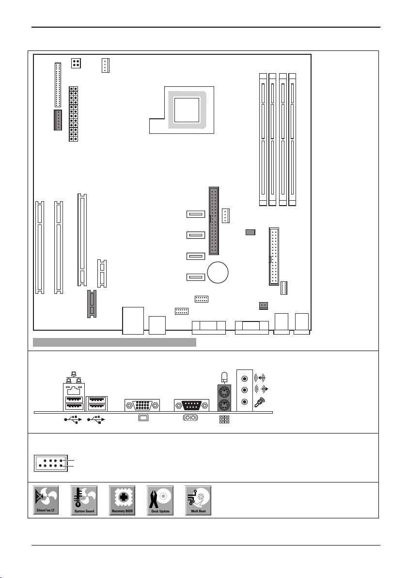
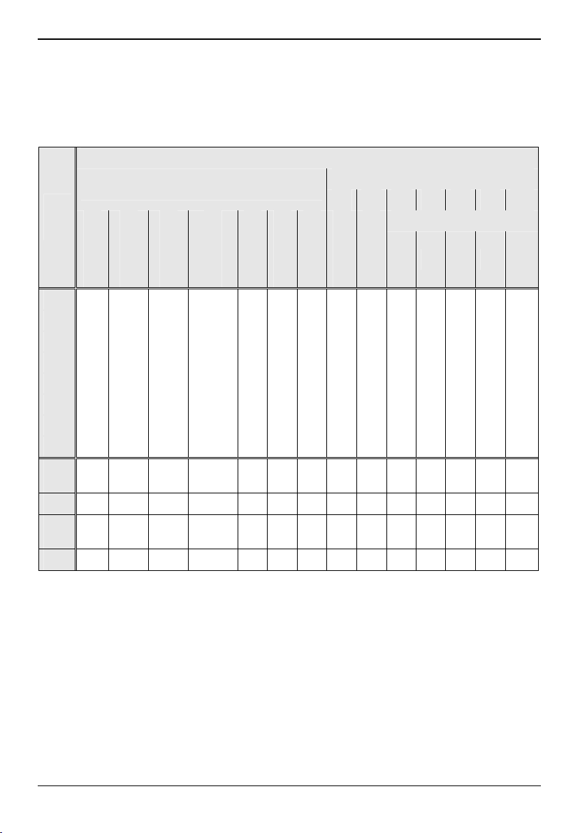
Mainboard D2461 – Internal connectors and slots
Slot 1
Slot 2
Slot 3
Slot 4
Front panel
Power supply
control
Additional
power
supply
Power supply
Fan 1
SATA 4
SATA 3
PCI Express x16
PCI
PCI
PCI Express x1
DVI
SATA 2
SATA 1
USB
Optionale Komponenten / Optional components
External connectors rear
USB – dual channel
1
2
1 = VCC C
2 = VCC D
3 = Data negative C
4 = Data negative D
5 = Data positive C
Fan 2
TPM
IDE-drives 1/2
Battery
USB
Intrusion
Floppy disc drive
Front
Audio
6 = Data positive D
7 = GND
8 = GND
9 = Key
10 = Not connected
A26361-D2461-Z110-1-8N19, Ausgabe 2
Page 6
Mainboard D2461
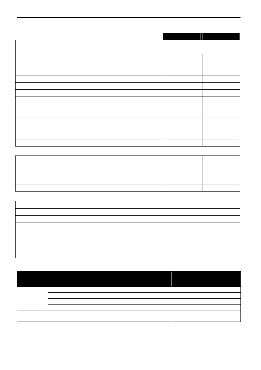
List of onboard features D2461-A/B D2461-C
Chipset AMD AM2
nVIDIA C51PVG/MCP51
Board size µBTX µBTX
VGA
Audio / 6-channel / S/PDIF / - / - / - / Buzzer / int. Speaker Support - / - /
LAN 1 Gbit / 100 Mbit / 10 Mbit / / / /
LAN ASF / AoL / WoL / Boot - / - / / - / - / /
Serial-ATA2 / ATA / RAID / - / / /
FireWireTM / USB 2.0 - / - /
FAN monitored PSU** / CPU (FAN1) / AUX1 (FAN2) / AUX2 (FAN3) / - / - / - - / - / - / FAN controlled PSU** / CPU (FAN1) / AUX1 (FAN2) / AUX2 (FAN3) / / / - - / / / TEMP monitored CPU/ONB1/ONB2/HDD / / - / - / / - / SmartCard SystemLock (USB / serial) / - / Fujitsu Siemens Computers Keyboard Power Button Support
List of special onboard features
Silent Fan / Silent Fan LT - / - /
System Guard / Silent Drives / /
Recovery BIOS / Desk Update / Multi Boot / / / /
Safe Standby / HDD Password - / - - / Logo Boot / Intel On Screen Branding / - / -
** not supported by standard Power Supplies
Special Features
Green Edition Halogen-free and lead-reduced product
Silent Fan LT Independent temperature related fan control
System Guard View Silent Fan LT
Silent Drives Noise reduction for optical and hard disk drives
Recovery BIOS Restores a disrupted BIOS
Desk Update Simple driver update with DU CD
Multi Boot Comfortable boot from any boot device
Power Supply Requirements
Source Voltage
+ 12 V +/– 5 % 11 A 15 A
Main Power – 12 V +/– 10 % 0.05 A 0.05 A
Supply + 5 V +/– 5 % 6.0 A 6.0 A
+ 3.3 V +/– 5 % 2.0 A 2.0 A
Aux. Power
Supply
+ 5 V +/– 5 % 2 A 2 A
- for onboard components (worst case)
Maximal
variation
Mainboard current
(Maximal) D2461-A/B
Mainboard current
(Maximal) D2461-C
A26361-D2461-Z110-1-8N19, Ausgabe 2
Page 7

Mainboard D2461
Hinweise zu Baugruppen
Beachten Sie bei Baugruppen mit EGB unbedingt Folgendes:
● Sie müssen sich statisch entladen (z. B. durch Berühren eines geerdeten
Gegenstandes), bevor Sie mit Baugruppen arbeiten.
● Verwendete Geräte und Werkzeuge müssen frei von statischer Aufladung sein.
● Ziehen Sie den Netzstecker, bevor Sie Baugruppen stecken oder ziehen.
● Fassen Sie die Baugruppen nur am Rand an.
● Berühren Sie keine Anschluss-Stifte oder Leiterbahnen auf der Baugruppe.
Eine Übersicht der Leistungsmerkmale finden Sie im Datenblatt!
Besondere Merkmale
Ihr Mainboard ist in verschiedenen Ausbaustufen erhältlich. Abhängig von der Konfiguration Ihres
Mainboards besitzt oder unterstützt das Mainboard bestimmte Merkmale.
In diesem Handbuch finden Sie die wichtigsten Eigenschaften dieses Mainboards beschrieben.
Weitere Informationen zu Mainboards finden Sie im Handbuch "Basisinformationen Mainboard" auf
der CD "User Documentation" oder "OEM Mainboard" bzw. im Internet.
Anschlüsse und Steckverbinder
Die Position der Anschlüsse und Steckverbinder Ihres Mainboards finden Sie am Anfang des
Handbuches.
Die markierten Komponenten und Steckverbinder müssen nicht auf dem Mainboard vorhanden sein.
Externe Anschlüsse
Die Position der externen Anschlüsse Ihres Mainboards finden Sie am Anfang des Handbuches.
PS/2-Tastaturanschluss, violett
(optional)
LAN
A26361-D2461-Z110-1-8N19, Ausgabe 2 Deutsch - 1
LAN-Anschluss (RJ-45)
Audioeingang (Line in), hellblau
Audioausgang (Line out), hellgrün
Serielle Schnittstelle, türkis
PS/2-Mausanschluss, grün (optional)
Mikrofonanschluss, rosa
USB – Universal Serial Bus, schwarz
VGA, blau
Page 8
Mainboard D2461
Grafikcontroller
● Programmierbarer Shader-Model 3.0 DirectX 9 Grafik Prozessor
● 300 MHz RAMDAC
● TMDS-Schnittstelle für DVI-Bildschirm
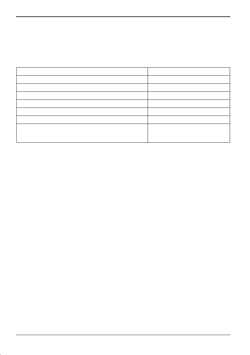
Auflösung (Farbtiefe bis zu 32 Bit/Pixel) Frequenz
1024 x 768 (empfohlen / max*) 120 / 200 Hz
1280 x 1024 (empfohlen / max*) 100 / 150 Hz
1600 x 1200 (empfohlen / max*) 85 / 100 Hz
1440 x 900 Widescreen TFT (VGA / DVI) x / x
1680 x 1050 Widescreen TFT (VGA / DVI) x / x
1920 x 1200 Widescreen TFT (VGA / DVI) x / x
* maximale Bildwiederholrate für die Grafikeinstellung. Die
Videoqualität kann verzerrt ("deteriorated") sein, wenn die
Maximaleinstellung verwendet wird.
2 - Deutsch A26361-D2461-Z110-1-8N19, Ausgabe 2
Page 9
Mainboard D2461
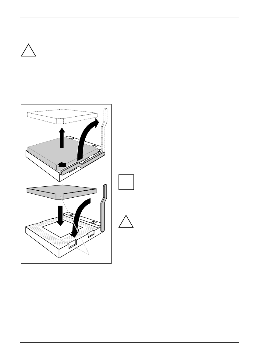
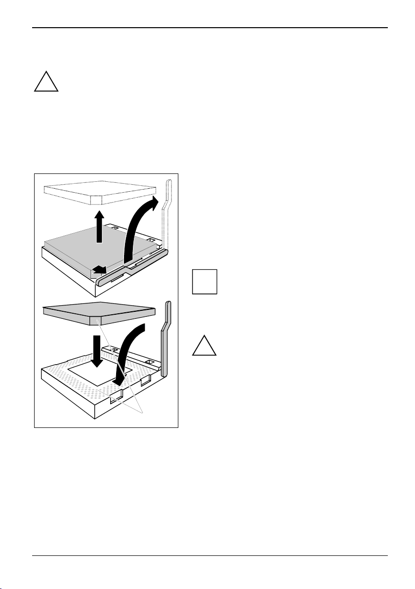
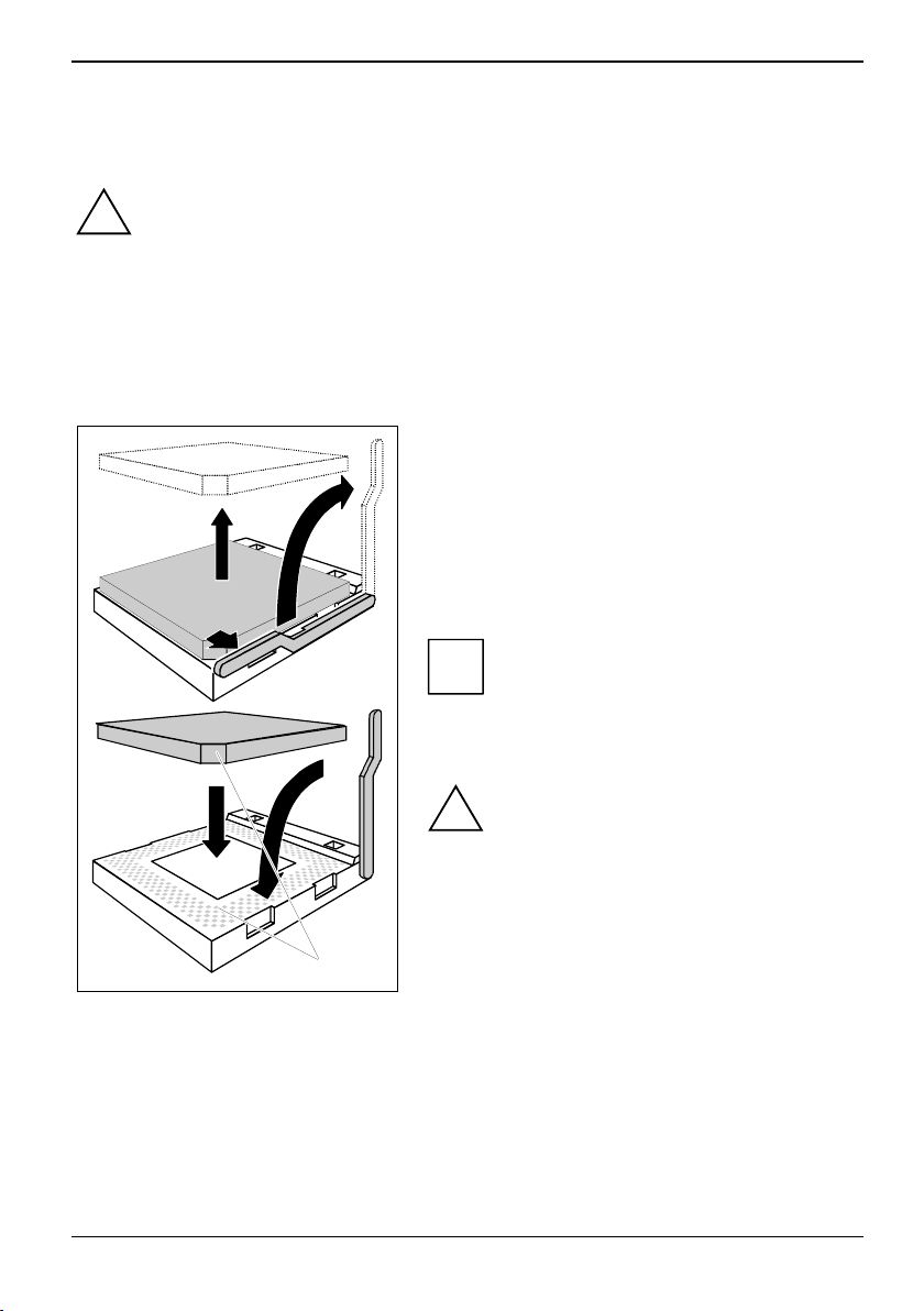
Prozessor ein-/ausbauen oder tauschen (mit Kühlkörper)
Technische Daten
● AMD Athlon 64/X2 und AMD Sempron mit bis zu 1 GHz Front Side Bus (Hypertransport) in der
● Eine aktuelle Liste der von diesem Mainboard unterstützten Prozessoren finden Sie im Internet
► Entfernen Sie einen eventuell vorhandenen Lüfter und den Kühlkörper.
► Je nach Prozessor-Variante werden für die Befestigung des Kühlkörpers noch Klammern
Für alle hier beschriebenen Arbeiten muss Ihr System vollständig von der Netzspannung
getrennt sein! Nähere Angaben dazu finden Sie in der Betriebsanleitung Ihres Systems.
!
Bauform AM2 (mPGA 940)
www.fujitsu-siemens.com/mainboards.
unter:
► Drücken Sie den Hebel in Pfeilrichtung (1) und
schwenken Sie ihn bis zum Anschlag nach
oben (2).
► Klappen Sie die Halterung nach oben.
3
2
1
4
5
A
mitgeliefert, die den Kühlkörper fixieren.
► Heben Sie den alten Prozessor aus dem
Steckplatz (3).
► Stecken Sie den neuen Prozessor so in den
Steckplatz, dass die abgeschrägte Ecke des
Prozessors mit der Codierung am Steckplatz (A)
von der Lage her übereinstimmt (4).
► Schwenken Sie den Hebel nach unten, bis er
► Je nach Ausbau-Variante müssen Sie eine
Die abgeschrägte Ecke des Prozessors
kann auch an einer anderen Stelle sein als
i
in der Abbildung dargestellt.
spürbar einrastet (5).
Bitte beachten Sie, dass je nach
verwendetem Kühlkörper unterschiedliche
!
Kühlkörperhalterungen auf dem Mainboard
benötigt werden.
Schutzfolie vom Kühlkörper abziehen oder den
Kühlkörper mit Wärmeleitpaste bestreichen, bevor
Sie ihn aufsetzen.
A26361-D2461-Z110-1-8N19, Ausgabe 2 Deutsch - 3
Page 10

Mainboard D2461
Hauptspeicher ein-/ausbauen oder tauschen
Technische Daten
Technologie: DDR2 400 / DDR2 533 / DDR2 667 / DDR2 800 ungepufferte DIMM Module
Gesamtgröße: 64 MBytes bis 8 GByte DDR2
Modulgrößen: 64, 128, 256, 512, 1024 oder 2048 MByte pro Modul
Eine aktuelle Liste der für dieses Mainboard empfohlenen Speichermodule finden Sie im Internet
www.fujitsu-siemens.com/mainboards.
unter:
Es muss mindestens ein Speichermodul eingebaut sein. Speichermodule mit unterschiedlicher
Speicherkapazität können kombiniert werden.
!
i
240-Pin; 1,8 V; 64 Bit, ohne ECC
Es dürfen nur ungepufferte 1,8 V-Speichermodule ohne ECC verwendet werden.
DDR2-Speichermodule müssen der PC2-3200U- oder PC2-4200U- oder PC2-5300U- oder
PCU2-6400U-Spezifikation entsprechen.
Wenn Sie mehr als ein Speichermodul verwenden, dann achten Sie darauf, die
Speichermodule auf beide Speicherkanäle aufzuteilen. Dadurch nutzen Sie die
Performancevorteile des Dual-Channel-Mode.
Die maximale Systemperformance ist gegeben, wenn in Channel A und Channel B
identische Speichermodule verwendet werden.
Um die Bestückung zu erleichtern, sind die Steckplätze (Slots) farbig gekennzeichnet.
Wenn Sie die Speichermodule einstecken, beginnen Sie mit dem Steckplatz, der am
weitesten vom Prozesser entfernt ist (Slot 4).
Bei einer Speicherkonfiguration von 4 GByte kann der sichtbare und benutzbare
Hauptspeicher auf bis zu 3,5 GByte reduziert sein (abhängig von der Konfiguration des
Systems).
Mehr als 4 GByte Hauptspeicher können nur mit entsprechendem Betriebssystem genutzt
werden.
4
3
Slot Channel
2
1
zu verwendender Steckplatz 1 2 3 4
Channel A, Slot 1 X
Channel B, Slot 2 X X
Channel A, Slot 3 X X X
Channel B, Slot 4 X X X X
Der Ein-/Ausbau ist im Handbuch "Basisinformationen Mainboard" beschrieben.
4 - Deutsch A26361-D2461-Z110-1-8N19, Ausgabe 2
Anzahl der gesteckten Speichermodule
B
A
B
A
Page 11

Mainboard D2461
PCI-Bus-Interrupts – Auswahl des richtigen PCI-Steckplatzes
Umfangreiche Informationen zu diesem Abschnitt finden Sie im Handbuch "Basisinformationen
Mainboard".
Welche ISA IRQs den PCI IRQ Lines zugeordnet werden, wird normalerweise automatisch vom
BIOS festgelegt (siehe Beschreibung "BIOS-Setup").
Monofunktionale Erweiterungskarten
PCI-/PCI-Express-Erweiterungskarten benötigen maximal einen Interrupt, der als PCI-Interrupt INT A
bezeichnet wird. Erweiterungskarten, die keinen Interrupt benötigen, können in einen beliebigen
Steckplatz eingebaut werden.
Um optimale Stabilität, Performance und Kompatibilität zu erreichen, vermeiden Sie die
mehrfache Nutzung von ISA IRQs oder PCI IRQ Lines (IRQ Sharing). Sollte IRQ Sharing
i
nicht zu umgehen sein, so müssen alle beteiligten Geräte und deren Treiber IRQ Sharing
unterstützen.
A26361-D2461-Z110-1-8N19, Ausgabe 2 Deutsch - 5
Page 12
Mainboard D2461
Multifunktionale Erweiterungskarten oder Erweiterungskarten mit integrierter PCI-PCI Bridge
Diese Erweiterungskarten benötigen bis zu vier PCI-Interrupts: INT A, INT B, INT C, INT D. Wie viele
und welche dieser Interrupts verwendet werden, entnehmen Sie der mitgelieferten Dokumentation
der Karte.
Die Zuordnung der PCI-Interrupts zu den IRQ Lines finden Sie in der folgenden Tabelle:
Controller or slot INT
On board controller
PCI
1 2 3 4 - - -
INT
LINE
USB 1.1
USB 2.0
1 (A)
2 (B)
3 (C)
4 (D)
5 (E)
6 (F)
7 (G)
8 (H)
ID
SEL
IDE
- - X X - - - - B A - - -
X
X - - - - - - - A B - - -
-
- - - - - - - - D C - - -
-
- - - - X - - - C D - - -
-
- - - - - - - - - - - -
-
- - - - - - - - - - - -
-
- - - - - - - - - - - -
-
- - - - - - - - - - - -
-
- - - - - - - - - 21 23 - - -
SATA 0/1
HD Audio
LAN
VGA
PCIe x16
Dev# 0Bh 0Bh 0Dh 0Eh/0Fh 10h 14h 05h 02h 03h 05h 07h - - -
Func
tion#
0 1 0 0 1 0 0 0 0 0 0 - - -
Bus# 0 0 0 0 0 0 0 0 0 4 4 - - -
* with onboard Grafic
Verwenden Sie zuerst PCI-/PCI-Express-Steckplätze, die über eine einzige PCI IRQ Line verfügen
(kein IRQ Sharing). Wenn Sie einen anderen PCI-/PCI-Express-Steckplatz mit IRQ Sharing
benutzen müssen, überprüfen Sie, ob die Erweiterungskarte IRQ Sharing mit den anderen Geräten
auf dieser PCI IRQ Line einwandfrei unterstützt. Auch die Treiber aller Karten und Komponenten an
dieser PCI IRQ Line müssen IRQ Sharing unterstützen.
Mechanical slot
PCI Slot
1 2 - - -
PCIe x1
6 - Deutsch A26361-D2461-Z110-1-8N19, Ausgabe 2
Page 13

Mainboard D2461
BIOS-Update
Wann sollte ein BIOS-Update durchgeführt werden?
Fujitsu Siemens Computers stellt neue BIOS-Versionen zur Verfügung, um die Kompatibilität zu
neuen Betriebssystemen, zu neuer Software oder zu neuer Hardware zu gewährleisten. Außerdem
können neue BIOS-Funktionen integriert werden.
Ein BIOS-Update sollte auch immer dann durchgeführt werden, wenn ein Problem besteht, das sich
durch neue Treiber oder neue Software nicht beheben lässt.
Wo gibt es BIOS-Updates?
Im Internet unter
Wie funktioniert ein BIOS-Update?
Sie haben zwei Möglichkeiten:
1. BIOS-Update unter DOS mit startfähiger BIOS-Update-Diskette - Kurzbeschreibung
► Laden Sie die Update-Datei von unserer Internet-Seite auf Ihren PC.
► Legen Sie eine leere Diskette (1,44 MByte) ein.
► Führen Sie die Update-Datei aus (z. B.
► Es wird eine startfähige Update-Diskette erstellt. Lassen Sie diese Diskette im Laufwerk.
► Starten Sie den PC neu.
► Folgen Sie den Bildschirmanweisungen.
i
2. BIOS-Update unter Windows mit dem Utility DeskFlash
Ein BIOS-Update kann mit dem Utility
DeskFlash befindet sich auf der CD "Drivers & Utilities" (unter DeskUpdate).
www.fujitsu-siemens.com/mainboards finden Sie die BIOS-Updates.
2461103.EXE).
Detaillierte Informationen zum BIOS-Update unter DOS finden Sie im Handbuch zum
"BIOS-Setup" (CD "Drivers & Utilities").
DeskFlash auch direkt unter Windows durchgeführt werden.
A26361-D2461-Z110-1-8N19, Ausgabe 2 Deutsch - 7
Page 14

Mainboard D2461
8 - Deutsch A26361-D2461-Z110-1-8N19, Ausgabe 2
Page 15
Mainboard D2461
Information about boards
Be sure to observe the following for boards with ESD:
● You must always discharge static build up (e.g. by touching a grounded object)
before working.
● The equipment and tools you use must be free of static charges.
● Remove the power plug from the mains supply before inserting or removing
boards containing ESDs.
● Always hold boards with ESDs by their edges.
● Never touch pins or conductors on boards fitted with ESDs.
An overview of the features is provided in the data sheet.
Special features
Your mainboard is available in different configuration levels. Depending on the configuration, your
mainboard is equipped with or supports special features.
This manual describes the most important properties of this mainboard.
Additional information on mainboards is contained in the manual "Basic information on mainboard"
on the "User Documentation" or "OEM Mainboard" CDs, or on the Internet.
Interfaces and connectors
The location of the interfaces and connectors of your mainboard is specified at the beginning of the
manual.
The components and connectors marked are not necessarily present on the mainboard.
External ports
The location of the external connections of your mainboard is specified at the beginning of the
manual.
PS/2 keyboard port, purple
(optional)
LAN
A26361-D2461-Z110-1-8N19, edition 2 English - 1
LAN port (RJ-45)
Audio input (Line in), light blue
Audio output (Line out), light green
Serial interface, turquoise
PS/2 mouse port, green (optional)
Microphone jack (mono), pink
USB - Universal Serial Bus, black
VGA, blue
Page 16

Mainboard D2461
Graphic Controller
● Programmable shader model 3.0 DirectX 9 graphic processor
● 300 MHz RAMDAC
● TMDS interface for DVI screen
Resolution (Colour depth up to 32 bit/pixel) Frequency
1024 x 768 (recommended / max*) 120 / 200 Hz
1280 x 1024 (recommended / max*) 100 / 150 Hz
1600 x 1200 (redommended / max*) 85 / 100 Hz
1440 x 900 Widescreen TFT (VGA / DVI) x / x
1680 x 1050 Widescreen TFT (VGA / DVI) x / x
1920 x 1200 Widescreen TFT (VGA / DVI) x / x
* max. refresh rate for the graphic setting. When the max.
setting is used the video quality may deteriorate.
2 - English A26361-D2461-Z110-1-8N19, edition 2
Page 17
Mainboard D2461
Installing/removing or replacing processor (with heat sink)
Technical data
● AMD Athlon 64/X2 and AMD Sempron with up to 1 GHz Front Side Bus (Hypertransport) in the
● A current list of the processors supported by this mainboard is available on the Internet at:
► Remove the fan that there may be and the heat sink.
Disconnect the system from the mains voltage before performing any of the tasks
described below. Details are contained in the operating manual of your system.
!
AM2 (mPGA 940) design
www.fujitsu-siemens.com/mainboards.
► Pull the lever in the direction of the arrow (1) and
lift it as far as it will go (2).
► Fold up the frame.
► Remove the old processor from the socket (3).
3
2
1
4
5
► Insert the new processor in the socket so that the
angled corner of the processor matches the
coding on the socket (A) with regard to the
position (4).
► Push the lever back down until it clicks into
► Depending on the configuration variant, you must
The angled corner of the processor can also
be at a different location than shown in the
i
illustration.
place (5).
Please note that, depending on the heat
sink used, different heat sink mounts are
!
required on the mainboard.
pull a protective foil off the heat sink or coat the
heat sink with heat conducting paste before fitting
it.
A
► Depending on the processor variant, clips may also be supplied for mounting the heat sink that
fix it in place.
A26361-D2461-Z110-1-8N19, edition 2 English - 3
Page 18

Mainboard D2461
Installing/removing or replacing main memory
Technical data
Technology: DDR2 400 / DDR2 533 / DDR2 667 and DDR2 800 unbuffered DIMM modules
Size: 64 Mbytes to 8 Gbyte DDR
Granularity: 64, 128, 256, 512, 1024 or 2048 Mbyte for one socket
A current list of the memory modules recommended for this mainboard is available on the Internet
www.fujitsu-siemens.com/mainboards.
at:
At least one memory module must be installed. Memory modules with different memory capacities
can be combined.
!
i
240-Pin; 1.8 V; 64 Bit, without ECC
You may use only unbuffered 1.8 V memory modules without ECC.
DDR memory modules must meet the PC2-3200U- or PC2-4200U- or PC2-5300U- or
PCU2-6400U specification.
If you use more than one memory module, then make sure to distribute the memory
modules over both memory channels. By doing this you use the performance advantages
of the dual-channel mode.
Maximum system performance is achieved when identical memory modules are used in
Channel A and Channel B.
To simplify equipping, the slots are colour coded.
When inserting the memory modules start with the slot located the furthest away from the
processor (slot 4).
With a memory configuration of 4 Gbytes the visible and usable main memory can be
reduced down to 3.5 Gbytes (depending on the system configuration).
More than 4 GByte main memory can only be used with a corresponding operating
system.
4
3
Slot Channel
2
1
slot to be used 1 2 3 4
Channel A, slot 1 X
Channel B, slot 2 X X
Channel A, slot 3 X X X
Channel B, slot 4 X X X X
The installation/removal is described in the "Basic information on mainboard" manual.
4 - English A26361-D2461-Z110-1-8N19, edition 2
Number of inserted memory modules
B
A
B
A
Page 19

Mainboard D2461
PCI bus interrupts - Selecting correct PCI slot
Extensive information on this section is contained in the manual "Basic information on mainboard".
Which ISA IRQs are assigned to the PCI IRQ Lines is normally automatically specified by the BIOS
(see "BIOS Setup" description).
Monofunctional expansions cards
PCI/PCI Express expansion cards require a maximum of one interrupt, which is called the PCI
interrupt INT A. Expansion cards that do not require an interrupt can be installed in any desired slot.
To achieve optimum stability, performance and compatibility, avoid the multiple use of ISA
IRQs or PCI IRQ Lines (IRQ sharing). Should IRQ sharing be unavoidable, then all
i
involved devices and their drivers must support IRQ sharing.
A26361-D2461-Z110-1-8N19, edition 2 English - 5
Page 20

Mainboard D2461
Multifunctional expansion cards or expansion cards with integrated PCI-PCI bridge
These expansion cards require up to four PCI interrupts: INT A, INT B, INT C, INT D. How many and
which of these interrupts are used is specified in the documentation provided with the card.
The assignment of the PCI interrupts to the IRQ Lines is shown in the following table:
Controller or slot INT
On board controller
PCI
1 2 3 4 - - -
INT
LINE
USB 1.1
USB 2.0
1 (A)
2 (B)
3 (C)
4 (D)
5 (E)
6 (F)
7 (G)
8 (H)
ID
SEL
IDE
- - X X - - - - B A - - -
X
X - - - - - - - A B - - -
-
- - - - - - - - D C - - -
-
- - - - X - - - C D - - -
-
- - - - - - - - - - - -
-
- - - - - - - - - - - -
-
- - - - - - - - - - - -
-
- - - - - - - - - - - -
-
- - - - - - - - - 21 23 - - -
SATA 0/1
HD Audio
LAN
VGA
PCIe x16
Dev# 0Bh 0Bh 0Dh 0Eh/0Fh 10h 14h 05h 02h 03h 05h 07h - - -
Func
tion#
0 1 0 0 1 0 0 0 0 0 0 - - -
Bus# 0 0 0 0 0 0 0 0 0 4 4 - - -
* with onboard Grafic
Use first PCI/PCI Express slots that have a single PCI IRQ Line (no IRQ sharing). If you must use
another PCI/PCI Express slot with IRQ sharing, check whether the expansion card properly supports
IRQ sharing with the other devices on this PCI IRQ Line. The drivers of all cards and components on
this PCI IRQ Line must also support IRQ sharing.
Mechanical slot
PCI Slot
1 2 - - -
PCIe x1
6 - English A26361-D2461-Z110-1-8N19, edition 2
Page 21

Mainboard D2461
BIOS update
When should a BIOS update be carried out?
Fujitsu Siemens Computers makes new BIOS versions available to ensure compatibility to new
operating systems, new software or new hardware. In addition, new BIOS functions can also be
integrated.
A BIOS update should always also be carried out when a problem exists that cannot be solved with
new drivers or new software.
Where can I obtain BIOS updates?
The BIOS updates are available on the Internet at
How does a BIOS update work?
You have two ways of doing this:
1. BIOS update under DOS with bootable BIOS update floppy disk - brief description
► Download the update file from out website to your PC.
► Insert an empty floppy disk (1.44 Mbyte).
► Run the update file (e.g.
► A bootable update floppy disk is created. Leave this floppy disk in the drive.
► Restart the PC.
► Follow the instructions on screen.
2. BIOS update under Windows with DeskFlash utility
A BIOS update can also be carried out directly under Windows with the
contained on the "Drivers & Utilities" CD (under
Detailed information on the BIOS update under DOS is provided in the manual on "BIOS
Setup" ("Drivers & Utilities" CD).
i
2461103.EXE).
www.fujitsu-siemens.com/mainboards.
DeskFlash utility. DeskFlash is
DeskUpdate).
A26361-D2461-Z110-1-8N19, edition 2 English - 7
Page 22

Mainboard D2461
8 - English A26361-D2461-Z110-1-8N19, edition 2
Page 23

Mainboard D2461
Remarques relatives aux cartes
Respectez impérativement les consignes suivantes avec les cartes équipées de
composants sensibles à l'électricité statique :
● Vous devez vous décharger de l'électricité statique (en touchant un objet relié
à la terre, par exemple) avant de manipuler les cartes.
● Les appareils et outils utilisés doivent être dépourvus de toute charge statique.
● Débranchez les câbles avant de connecter ou de déconnecter les cartes.
● Manipulez les cartes en les tenant uniquement par leurs bords.
● Evitez de toucher les broches ou les circuits d'une carte.
Vous trouverez un aperçu des caractéristiques de performances dans la fiche technique !
Caractéristiques
Votre carte mère est disponible en plusieurs niveaux d'équipement. Suivant sa configuration, votre
carte mère possède ou supporte certaines caractéristiques.
Vous trouverez dans ce manuel une description des principales caractéristiques de cette carte mère.
Vous trouverez d'autres informations sur les cartes mères dans le manuel "Basic information on
mainboard" sur le CD "User Documentation" ou "OEM Mainboard" ainsi que sur Internet.
Ports et connecteurs
Vous trouverez au début du manuel la position des ports et des connecteurs sur votre carte mère.
Les composants et connecteurs marqués ne sont pas obligatoirement disponibles sur la carte mère.
Ports externes
Vous trouverez au début du manuel la position des ports externes de votre carte mère.
Port clavier PS/2, violet (en option)
LAN
A26361-D2461-Z110-1-8N19, édition 2 Français - 1
Port LAN (RJ-45)
Entrée audio (Line in), bleu ciel
Sortie audio (Line out), vert clair
Interface série, turquoise
Port souris PS/2, vert (en option)
Port microphone, rose
USB – Universal Serial Bus, noir
VGA, bleu
Page 24

Mainboard D2461
Contrôleur graphique
● Processeur graphique Shader Model 3.0 DirectX 9 programmable
● RAMDAC 300 MHz
● Interface TMDS pour écran DVI
Résolution (profondeur de couleur jusqu’à 32 bits/pixel) Fréquence
1024 x 768 (recommandé / max*) 120 / 200 Hz
1280 x 1024 (recommandé / max*) 100 / 150 Hz
1600 x 1200 (recommandé / max*) 85 / 100 Hz
1440 x 900 Widescreen TFT (VGA / DVI) x / x
1680 x 1050 Widescreen TFT (VGA / DVI) x / x
1920 x 1200 Widescreen TFT (VGA / DVI) x / x
* fréquence de rafraîchissement maximale de l’image pour
le réglage graphique. La qualité d’image peut être
détériorée en cas d’utilisation du réglage maximum.
2 - Français A26361-D2461-Z110-1-8N19, édition 2
Page 25
Mainboard D2461
Monter/démonter ou remplacer le processeur (avec refroidisseur)
Caractéristiques techniques
● AMD Athlon 64/X2 et AMD Sempron avec Front Side Bus jusqu’à 1 GHz (HyperTransport)
● Vous trouverez une liste actualisée des processeurs supportés par cette carte mère sur
► Retirez le ventilateur éventuel ainsi que le refroidisseur.
► Des clips de fixation du refroidisseur sont compris dans la livraison suivant le type de
Avant de procéder à toutes les étapes décrites ici, il est indispensable de séparer
intégralement votre système de la tension de secteur ! Vous trouverez à ce propos
!
d'autres indications détaillées dans le manuel de votre système.
dans la version AM2 (mPGA 940)
Internet à l'adresse suivante :
3
1
4
5
processeur.
www.fujitsu-siemens.com/mainboards.
► Soulevez le levier dans le sens de la flèche (1) et
relevez-le jusqu’à la butée (2).
► Relevez le support vers le haut.
► Retirez l’ancien processeur de son logement (3).
2
► Placez le nouveau processeur dans son logement
de telle manière que le coin biseauté du
processeur coïncide (4) avec le motif formé par
les perforations du logement (A).
i
► Rabaissez le levier vers le bas jusqu’à l’entendre
s’encastrer (5).
!
► Suivant le modèle, vous devez soit retirer un film
de protection du refroidisseur soit enduire le
refroidisseur d’une pâte conductrice de chaleur
avant de le remonter.
A
L'angle biseauté du processeur peut
également être situé à un autre endroit que
celui indiqué sur le dessin.
Veuillez tenir compte du fait que les clips de
fixation du refroidisseur nécessaires sur la
carte mère varient en fonction du type de
refroidisseur utilisé.
A26361-D2461-Z110-1-8N19, édition 2 Français - 3
Page 26

Mainboard D2461
Monter/démonter ou remplacer le processeur
Caractéristiques techniques
Technologie : modules DIMM DDR2 400 / DDR2 533 / DDR2 667 / DDR2 800 sans tampon
Taille : 64 Mo jusqu'à 8 Go DDR2
Tailles des modules : 64, 128, 256, 512, 1024 ou 2048 Moctets par module
Vous trouverez une liste actualisée des modules d'extension mémoire recommandés pour cette
carte mère sur Internet à l'adresse suivante :
Au moins un module d’extension mémoire doit être monté. Il est possible de combiner des modules
d’extension mémoire de capacités différentes.
!
i
240 broches ; 1,8 V ; 64 bits, non-CCE
www.fujitsu-siemens.com/mainboards.
Vous ne pouvez utiliser que des modules mémoires 1,8 V sans tampon sans CCE.
Les modules mémoire DDR2 doivent être conformes à la spécification PC2-3200U, PC2-
4200U, PC2-5300U ou PCU2-6400U.
Si vous utilisez plus d’un module mémoire, veillez à répartir les modules mémoire sur les
deux canaux mémoire. Cette précaution vous permet de bénéficier des gains de
performances offerts par le mode bi-canal (dual channel).
Les performances système maximales s’obtiennent lorsque les modules de mémoire
utilisés dans le canal A et dans le canal B sont identiques.
Pour faciliter le montage des modules, les emplacements (slots) sont marqués de codes
couleur.
Lorsque vous enfichez les modules mémoire, commencez par l’emplacement le plus
éloigné du processeur (slot 4).
Dans le cas d’une configuration mémoire de 4 Goctets, la mémoire visible et utilisable
peut être réduite jusqu’à 3,5 Goctets (selon la configuration du système).
Seul un système d’exploitation approprié permet d’utiliser plus de 4 Goctets de mémoire
centrale.
4
3
Slot Channel
2
1
emplacement à utiliser 1 2 3 4
canal A, slot 1 X
canal B, slot 2 X X
canal A, slot 3 X X X
canal B, slot 4 X X X X
Le montage/démontage est décrit dans le manuel "Basic information on mainboard".
4 - Français A26361-D2461-Z110-1-8N19, édition 2
Nombre de modules mémoire installés
B
A
B
A
Page 27

Mainboard D2461
Interruptions de BUS PCI – Sélection du logement PCI adéquat
Vous trouverez de plus amples informations sur ce chapitre dans le manuel "Basic information on
mainboard".
L'affectation des IRQ ISA aux lignes IRQ PCI est normalement fixée automatiquement par le BIOS
(voir description "Setup du BIOS").
Cartes d’extension monofonctionnelles
Les cartes d’extension PCI/PCI Express standard ont besoin tout au plus d’une interruption,
désignée comme interruption PCI INT A. Les cartes d’extension ne nécessitant aucune interruption
peuvent être montées dans n’importe quel logement.
Afin d’obtenir une stabilité, des performances et une compatibilité optimales, évitez
l’utilisation multiple de lignes IRQ ISA ou IRQ PCI (IRQ Sharing). Si l’IRQ Sharing est
i
inévitable, tous les périphériques impliqués et leurs pilotes doivent supporter l’IRQ
Sharing.
A26361-D2461-Z110-1-8N19, édition 2 Français - 5
Page 28

Mainboard D2461
Cartes d'extension multifonctions ou cartes d'extension avec pont PCI-PCI intégré
Ces cartes d’extension nécessitent jusqu’à quatre interruptions PCI : INT A, INT B, INT C, INT D.
Pour savoir combien et lesquelles de ces interruptions sont utilisées, reportez-vous à la
documentation fournie avec la carte.
L’affectation des interruptions PCI aux lignes IRQ est reprise dans le tableau suivant :
Contrôleur ou slot INT
On board controller
PCI
1 2 3 4 - - -
INT
LINE
USB 1.1
USB 2,0
IDE
1 (A)
2 (B)
3 (C)
4 (D)
5 (E)
6 (F)
7 (G)
8 (H)
ID
SEL
Dev
0Bh 0Bh 0Dh 0Eh/0Fh 10h 14h 05h 02h 03h 05h 07h - - -
#
Func
tion#
- - X X - - - - B A - - -
X
X - - - - - - - A B - - -
-
- - - - - - - - D C - - -
-
- - - - X - - - C D - - -
-
- - - - - - - - - - - -
-
- - - - - - - - - - - -
-
- - - - - - - - - - - -
-
- - - - - - - - - - - -
-
- - - - - - - - - 21 23 - - -
0 1 0 0 1 0 0 0 0 0 0 - - -
SATA 0/1
HD Audio
LAN
VGA
PCIe x16
Bus# 0 0 0 0 0 0 0 0 0 4 4 - - -
* with onboard Grafic
Utilisez d'abord les logements PCI/PCI Express qui disposent d'une seule ligne IRQ PCI (pas d'IRQ
Sharing). Si vous devez utiliser un autre logement PCI/PCI Express avec IRQ Sharing, vérifiez si la
carte d'extension supporte intégralement l'IRQ Sharing avec les autres périphériques sur cette ligne
IRQ PCI. Les pilotes de toutes les cartes et composants de cette ligne IRQ PCI doivent également
supporter l’IRQ Sharing.
Mechanical slot
PCI Slot
1 2 - - -
PCIe x1
6 - Français A26361-D2461-Z110-1-8N19, édition 2
Page 29

Mainboard D2461
Setup du BIOS: mise à jour
Quand une mise à jour du BIOS est-elle nécessaire ?
Fujitsu Siemens Computers propose de nouvelles versions du BIOS afin de garantir la compatibilité
avec les nouveaux systèmes d’exploitation, les nouveaux logiciels ou le nouveau matériel. De
nouvelles fonctionnalités du BIOS peuvent en outre être intégrées.
Une mise à jour du BIOS est toujours nécessaire en cas de problème ne pouvant être résolu par
l’utilisation de nouveaux pilotes ou logiciels.
Où se procurer des mises à jour du BIOS ?
Les mises à jour du BIOS sont disponibles sur Internet à l’adresse suivante :
siemens.com/mainboards
Comment fonctionne une mise à jour du BIOS ?
Deux possibilités s'offrent à vous :
1. Mise à jour du BIOS sous DOS avec disquette de mise à jour du BIOS opérationnelle Brève description
► Téléchargez sur votre PC le fichier de mise à jour sur notre page Internet.
► Introduisez une disquette vierge (1,44 Moctets).
► Lancez l'exécution du fichier de mise à jour (p. ex. :
► Une disquette amorçable de mise à jour est créée. Laissez cette disquette dans le lecteur de
disquettes.
► Redémarrez le PC.
► Suivez les instructions à l'écran.
2. Mise à jour du BIOS sous Windows avec l’utilitaire DeskFlash
Le BIOS peut également être mis à jour directement sous Windows avec l'utilitaire
DeskFlash se trouve sur le CD "Drivers & Utilities" (sous DeskUpdate).
Vous trouverez des informations détaillées sur la mise à jour du BIOS sous DOS dans le
manuel "BIOS-Setup" (CD "Drivers & Utilities").
i
.
2461103.EXE).
www.fujitsu-
DeskFlash.
A26361-D2461-Z110-1-8N19, édition 2 Français - 7
Page 30

Mainboard D2461
8 - Français A26361-D2461-Z110-1-8N19, édition 2
Page 31

Mainboard D2461
Yapı gruplarıyla ilgili uyarılar
EGB’li yapı gruplarında aşağıdaki hususları mutlaka dikkate alın:
● Yapı gruplarıyla çalışmadan önce statik olarak deşarj olmanız gerekir (örneğin
topraklanmış bir cisme dokunarak).
● Kullanılan cihazlar ve malzemeler statik şarjdan arınmış olmalıdır.
● Yapı gruplarını takmadan veya çekmeden önce fiş soketini çekin.
● Yapı gruplarını sadece kenarlardan tutun.
● Yapı gruplarındaki giriş pimlerine veya raylara dokunmayın.
Performans özellikleriyle ilgili bir genel bakışı bilgi sayfasında bulabilirsiniz!
Ana özellikler
Ana kartınız çeşitli sökme kademeleri şeklinde elde edilir. Ana kartınızın konfigürasyonuna bağımlı
olarak ana kartınız belirli özelliklere sahiptir veya destekler.
Bu el kitabında bu ana kartının önemli özellikleri açıklanmıştır.
Ana kartla ilgili kalan bilgileri “Ana kart temel bilgiler” el kitabında "User Documentation" yada "OEM
Mainboard" CD‘sinde veya Internet’te bulabilirsiniz.
Girişler ve soket bağlantısı
Ana kart girişlerinizin ve soket bağlantılarınızın konumunu el kitabının başlangıcında bulabilirsiniz.
İşaretlenen parçalar ve soket bağlantıları ana kartta bulunmamalıdır.
Harici girişler
Ana kart harici girişlerinizin konumunu el kitabının başlangıcında bulabilirsiniz.
PS/2 klavye girişi, mor (opsiyonel)
LAN
A26361-D2461-Z110-1-8N19, Basım 2 Türkçe - 1
LAN girişi (RJ-45)
Ses girişi (giriş), açık mavi
Ses çıkışı (çıkış), açık yeşil
Seri bağlantı noktası, turkuvaz
PS/2 fare girişi, mor (opsiyonel)
Mikrofon girişi, pembe
USB – Üniversal seri veri yolu, siyah
VGA, mavi
Page 32

Mainboard D2461
Grafik kontrolcüsü
● Programlanabilir Shader-Model 3.0 DirectX 9 Grafik işlemci
● 300 MHz RAMDAC
● DVI ekranı için TMDS bağlantı noktası
Çözünürlük (32 Bit/piksele kadar renk derinliği) Frekans
1024 x 768 (tavisye edilir / maks.*) 120 / 200 Hz
1280 x 1024 (tavisye edilir / maks.*) 100 / 150 Hz
1600 x 1200 (tavisye edilir / maks.*) 85 / 100 Hz
1440 x 900 Widescreen TFT (VGA / DVI) x / x
1680 x 1050 Widescreen TFT (VGA / DVI) x / x
1920 x 1200 Widescreen TFT (VGA / DVI) x / x
* grafik ayarı için maksimum tekrarlanma oranı. Maksimum
ayar kullanıldığında Video kalitesi kötüleşebilir.
2 - Türkçe A26361-D2461-Z110-1-8N19, Basım 2
Page 33

Mainboard D2461
İşlemcinin takılması/sökülmesi veya değiştirilmesi (soğutma gövdesiyle)
Teknik özellikler
● AMD Athlon 64/X2 ve AMD Sempron, AM2 (mPGA 940) yapısında 1 GHz ön yan veri yolu
● Bu ana kart tarafından desteklenen işlemcilerin güncel bir listesini Internet’te şu adreste
► Varsa fan ve soğutma gövdesini sökün.
Burada açıklanan tüm çalışmalar için sisteminiz tamamen ağ geriliminden ayrılmış
olmalıdır! Bununla ilgili detaylı bilgileri sisteminizin kullanım kılavuzunda bulabilirsiniz.
!
(Hypertransport) dahil
bulabilirsiniz:
www.fujitsu-siemens.com/mainboards.
► Kolu ok yönünde (1) bastırın ve dayanma
► Tutucuyu yukarı doğru katlayın.
► Eski işlemciyi oturduğu yerden (3) kaldırın.
3
2
1
► Yeni işlemciyi, işlemcinin eğik köşeleri oturulan
i
► Kolu hissedilecek şekilde oturana kadar aşağı
!
4
5
► Sökme türüne göre bir koruyucu folyoyu soğutma
noktasına kadar yukarı doğru (2) hareket ettirin.
yerdeki kodlamayla (A) aynı konumda olacak
şekilde yerleştirin (4).
İşlemcinin eğik köşeleri şekilde gösterilene
göre farklı bir yer de olabilir.
doğru hareket ettirin (5).
Kullanılan soğutma gövdesine göre çeşitli
soğutma gövdesi tutucularının ana kartta
gerekli olduğuna dikkat edin.
gövdesinden çıkartmalı veya yerleştirmeden önce
soğutma gövdesine ısı iletken macunu
sürmelisiniz.
A
► İşlemci türüne göre soğutma gövdesinin sabitleştirilmesi için, soğutma gövdesini sabitleyen
ilave mandallar gönderilir.
A26361-D2461-Z110-1-8N19, Basım 2 Türkçe - 3
Page 34

Mainboard D2461
Ana hafızanın takılması/sökülmesi veya değiştirilmesi
Teknik özellikler
Teknoloji: DDR2 400 / DDR2 533 / DDR2 667 / DDR2 800 DIMM modül
Toplam büyüklük: 64 MBayt ila 8 GBayt DDR2
Modül büyüklüğü: her modül için 64, 128, 256, 512, 1024 veya 2048 MBayt
Bu ana kart için tavsiye edilen hafıza modüllerinin güncel bir listesini Internet’te şu adreste
bulabilirsiniz:
En az bir hafıza modülü takılmış olmalıdır. Çeşitli hafıza kapasitesine sahip hafıza modülleri kombine
edilebilir.
!
i
240-Pin; 1,8 V; 64 Bit, ECC yok
www.fujitsu-siemens.com/mainboards.
Sadece ara belleğe alınmayan ECC’siz 1,8 V hafıza modülleri kullanılabilir.
DDR2 hafıza modülleri PC2-3200U- veya PC2-4200U veya PC2-5300U- veya PCU2-
6400U spesifikasyona uymalıdır.
Bir hafıza modülünden daha fazla kullandığınızda, hafıza modülünde her iki hafıza
kanalını paylaştırmayı unutmayın. Bu sayede çift kalan modunun performans
avantajlarından yararlanırsınız.
A kanalında ve B kanalında aynı hafıza büyüklüğü kullanıldığında, maksimum sistem
performansı gösterilmektedir.
Entegrasyonu kolaylaştırmak için, takılacak yerler (slot’lar) renkli olarak işaretlenmiştir.
Hafıza modülünü taktığınız zaman, işlemciden en fazla uzaklaşan yerden başlayın
(slot 4).
4 GBayt’lık bir hafıza konfigürasyonunda görülebilir ve kullanılabilir ana hafıza 3,5
GBayt’a kadar düşürülebilir (sistem konfigürasyonuna bağımlı olarak).
4 GBayt’lık ana hafızadan fazla olan hafızalar sadece ilgili işletim sistemiyle kullanılabilir.
4
3
Slot Channel
2
1
kullanılacak yerler 1 2 3 4
Kanal A, Slot 1 X
Kanal B, Slot 2 X X
Kanal A, Slot 3 X X X
Kanal B, Slot 4 X X X X
Takma/sökme işlemi “Ana kart temel bilgiler” el kitabında açıklanmıştır.
4 - Türkçe A26361-D2461-Z110-1-8N19, Basım 2
Takılan hafıza modüllerinin sayısı
B
A
B
A
Page 35

Mainboard D2461
PCI veri yolu kesintisi - Doğru PCI yerini seçmek
Bu bölümle ilgili geniş bilgileri “Ana kart temel bilgiler” el kitabında bulabilirsiniz.
Hangi ISA IRQ’leri PCI IRQ hattını düzenlediği, otomatik olarak BIOS tarafından belirlenir (bkz.
açıklama (BIOS ayarı”).
Tekli fonksiyonel geliştirme kartları
PCI-/PCI-Express geliştirme kartları PCI-Interrupt INT A olarak tanımlanan maksimum bir Interrupt
gerektirmektedir. Interrupt gerektirmeyen geliştirme kartları istenilen bir yere takılabilir.
En uygun dengeye, performansa ve uyumluluğa ulaşmak için, ISA IRQ oder PCI IRQ
hatlarının çok amaçlı kullanımından sakının (IRQ paylaşımı). IRQ paylaşımı
i
önlenemiyorsa, tüm katılımcı cihazlar ve bunların sürücüleri IRQ paylaşımını
desteklemelidir.
A26361-D2461-Z110-1-8N19, Basım 2 Türkçe - 5
Page 36

Mainboard D2461
Çok fonksiyonel geliştirme kartları veya entegre edilmiş PCI-PCI köprülü geliştirme kartları
Bu geliştirme kartları dört PCI-Interrupt‘a kadar ihtiyacı vardır: INT A, INT B, INT C, INT D. Bu
Interrupt’ların kaç sayıda ve hangilerinin kullanılacağı gönderilen kartların belgesinden alabilirsiniz.
IRC hatlarıyla ilgili PCI-Interrupt‘ların düzenini aşağıdaki tabloda bulabilirsiniz:
Controller or slot INT
On board controller
PCI
1 2 3 4 - - -
INT
LINE
USB 1.1
USB 2.0
1 (A)
2 (B)
3 (C)
4 (D)
5 (E)
6 (F)
7 (G)
8 (H)
ID
SEL
IDE
- - X X - - - - B A - - -
X
X - - - - - - - A B - - -
-
- - - - - - - - D C - - -
-
- - - - X - - - C D - - -
-
- - - - - - - - - - - -
-
- - - - - - - - - - - -
-
- - - - - - - - - - - -
-
- - - - - - - - - - - -
-
- - - - - - - - - 21 23 - - -
SATA 0/1
HD Audio
LAN
VGA
PCIe x16
Dev# 0Bh 0Bh 0Dh 0Eh/0Fh 10h 14h 05h 02h 03h 05h 07h - - -
Func
tion#
0 1 0 0 1 0 0 0 0 0 0 - - -
Bus# 0 0 0 0 0 0 0 0 0 4 4 - - -
* with onboard Grafic
Öncelikle tek bir PCU IRC hattına sahip olan PCI-/PCI-Express yerlerini kullanın (IRC paylaşımı yok).
IRQ paylaşımı olan başka bir PCI-/PCI-Express yerlerini kullanmak zorundaysanız, gelişmiş kartlara
ait IRQ paylaşımının diğer cihazlarla bu PCI IRC hattında kusursuzca desteklenip desteklenmediğini
kontrol edin. Bu PCI IRC hattındaki tüm kartların ve parçaların sürücüleri IRQ paylaşımını
desteklemelidir.
Mechanical slot
PCI Slot
1 2 - - -
PCIe x1
6 - Türkçe A26361-D2461-Z110-1-8N19, Basım 2
Page 37

Mainboard D2461
BIOS güncelleme
Bir BIOS güncelleme ne zaman yapılmalıdır?
Fujitsu Siemens Computers, yeni işletim sistemlerinin uyumluluğunu yeni yazılıma ve yeni donanıma
sağlamak için yeni BIOS versiyonlarını kullanıma sunar. Bunun dışında yeni BISO fonksiyonları
entegre edilebilir.
Bir BIOS güncelleme her zaman için, yeni sürücü veya yeni yazılımla giderilemeyecek düzeyde bir
problem varsa yapılmalıdır.
BIOS güncelleme nerededir?
Internet’te
Bir BIOS güncelleneme nasıl çalışır?
İki olanağınız var:
1. Başlatma özelliğine sahip BIO güncelleme disketi dahil DOS'tan BIOS güncelleme - Kısa açıklama
► Internet sayfamızda yer alan güncelleme dosyasını PC’nize yükleyin.
► Boş bir disket (1,44 MBayt) takın.
► Güncelleme dosyasını uygulayın (örn.
► Başlatma özelliğine sahip bir güncelleme disketi hazırlanır. Bu disketi sürücüde bırakın.
► PC’yi yeniden başlatın.
► Ekran talimatlarını takip edin.
2. Utility DeskFlash ile Windows’ta BIOS güncelleme
Bir BIOS güncellemeyi Utility
"Drivers & Utilities" kısmında bulunmaktadır (
www.fujitsu-siemens.com/mainboards linkinden BIOS güncellemeyi bulabilirsiniz.
2461103.EXE).
DOS kısmında BIOS güncellemeyle ilgili detaylı bilgileri “BIOS güncelleme” ile ilgili el
kitabında bulabilirsiniz (CD "Drivers & Utilities").
i
DeskFlash ile doğrudan Windows’ta yapılabilir. DeskFlash CD
DeskUpdate kısmında).
A26361-D2461-Z110-1-8N19, Basım 2 Türkçe - 7
Page 38

Mainboard D2461
8 - Türkçe A26361-D2461-Z110-1-8N19, Basım 2
Page 39

Mainboard D2461
Указания по модулям
Для модулей с EGB обязательно учитывайте следующее:
● Перед работой с модулями требуется статически разрядить свое тело
(например, посредством касания какого-либо заземленного предмета).
● Исключить возможность статического заряда используемых устройств и
инструментов.
● Перед установкой или снятием модулей выньте вилку сетевого кабеля из
розетки.
● Касайтесь только кромок модулей.
● Не прикасайтесь к штырьковым выводам или печатным проводникам
модуля.
Обзор производственных показателей Вы найдете в техническом паспорте!
Отличительные особенности
Вы можете приобрести Вашу материнскую плату в различных конфигурационных исполнениях.
Ваша материнская плата в зависимости от своей конфигурации обладает определенными
показателями или поддерживает их.
В этом Руководстве по эксплуатации Вы найдете описание важнейших свойств этой
материнской платы.
Дальнейшую информацию о материнских платах Вы найдете в руководстве "Basic information
on mainboard" ("Базисная информация о материнской плате") на компакт-диске "User
Documentation" или "OEM Mainboard" или же в Internet.
Порты и разъемы
Информацию о расположении портов и разъемов на Вашей материнской плате Вы найдете в
начале Руководства по эксплуатации.
Помеченные компоненты и разъемы могут отсутствовать на материнской плате.
A26361-D2461-Z110-1-8N19, Издание 2 Русский - 1
Page 40

Mainboard D2461
Внешние порты
Информацию о расположении внешних портов на Вашей материнской плате Вы найдете в
начале Руководства по эксплуатации.
Порт клавиатуры PS/2,
фиолетовый (опция)
LAN
Порт LAN (RJ-45)
Aудиовход (Line in), светло-синий
Аудиовыход (Line out), светлозеленый
Последовательный интерфейс,
бирюзовый
Графический контроллер
● Программируемый графический процессор Shader-Model 3.0 DirectX 9
● 300 МГц RAMDAC
● TMDS-интерфейс для DVI-монитора
Разрешение (глубина цвета до 32 бит/пиксель) Частота
1024 x 768 (рекомендуемая / максимальная*) 120 / 200 Гц
1280 x 1024 (рекомендуемая / максимальная*) 100 / 150 Гц
1600 x 1200 (рекомендуемая / максимальная*) 85 / 100 Гц
1440 x 900 Widescreen TFT (VGA / DVI) x / x
1680 x 1050 Widescreen TFT (VGA / DVI) x / x
1920 x 1200 Widescreen TFT (VGA / DVI) x / x
* максимальная частота регенерации изображения для
настройки графики. Видеоизображение может быть
искаженным ("deteriorated"), если используется
настройка максимальной частоты.
Порт мыши PS/2, зеленый (опция)
Порт микрофона, розовый
USB – Universal Serial Bus
(универсальная последовательная
шина), черный
VGA, синий
2 - Русский A26361-D2461-Z110-1-8N19, Издание 2
Page 41

Mainboard D2461
Монтаж/демонтаж или замена процессоров (с радиатором)
Технические данные
● Процессоры AMD Athlon 64/X2 и AMD Sempron с шиной Front Side Bus (Hypertransport)
● Актуальный список процессоров, поддерживаемых этой материнской платой, Вы найдете
► Снимите вентилятор и радиатор в случае их наличия.
► В зависимости от варианта процессора для крепления радиатора поставляются также
Для осуществления всех описанных здесь работ Ваша система должна быть
полностью отключена от сетевого напряжения! Более подробную информацию об
!
этом Вы найдете в руководстве по эксплуатации Вашей системы.
частотой до 1 ГГц в конструктивном исполнении AM2 (mPGA 940)
в Internet на сайте:
3
1
4
скобы, обеспечивающие фиксацию радиатора.
www.fujitsu-siemens.com/mainboards.
► Надавите на рычаг в направлении, указанном
стрелкой (1), и поверните его до упора
вверх (2).
► Поднимите устройство крепления вверх.
2
5
A
► Выньте старый процессор из монтажного
гнезда (3).
► Вставьте новый процессор в монтажное гнездо
таким образом, чтобы положение срезанного
угла процессора совпадало с кодировкой на
монтажном гнезде (A) (4).
► Поверните рычаг вниз до его ощутимой
► В зависимости от варианта конфигурации
Срезанный угол процессора может также
находиться в другом месте, чем место,
i
изображенное на рисунке.
фиксации (5).
Пожалуйста, учитывайте то, что в
зависимости от используемого радиатора
!
на материнской плате требуются
различные устройства крепления
радиатора.
перед установкой радиатора Вы должны снять
защитную пленку с радиатора, или же покрыть
радиатор теплопроводящей пастой.
A26361-D2461-Z110-1-8N19, Издание 2 Русский - 3
Page 42

Mainboard D2461
Монтаж/демонтаж или замена ОЗУ
Технические данные
Технология: DDR2 400 / DDR2 533 / DDR2 667 / DDR2 800 модули DIMM без буферизации
Общий объем памяти: от 64 Мбайт до 8 Гбайт DDR2
Объем памяти модулей: 64, 128, 256, 512, 1024 или 2048 Mбайт в каждом модуле
Актуальный список модулей памяти, рекомендованных для этой материнской платы, Вы
найдете в Internet на сайте:
Должен быть установлен хотя бы один модуль памяти. Можно комбинировать модули памяти с
различной ёмкостью ЗУ.
!
i
240-Pin; 1,8 В; 64 бит, без ECC
www.fujitsu-siemens.com/mainboards.
Допускается применение только модулей памяти без буферизации 1,8 В без ECC.
Модули памяти DDR2 должны соответствовать спецификации PC2-3200U- или PC2-
4200U или PC2-5300U- или PCU2-6400U.
Если вы используете больше одного модуля памяти, следите за тем, чтобы модули
памяти были распределены на обоих каналах с памятью. За счет этого Вы будете
использовать преимущества рабочих характеристик двухканального режима Dual-
Channel-Mode.
Максимальные рабочие характеристики системы достигаются, когда на каналах
Channel A и Channel B используются одинаковые модули памяти.
Для облегчения установки модулей гнезда (слоты) имеют цветную маркировку.
Если Вы устанавливаете модули памяти, начинайте с гнезда, которое расположено
дальше всего от процессора (слот 4).
При конфигурации памяти объемом 4 Гбайт видимое и используемое ОЗУ может
быть сокращено до 3,5 Гбайт (в зависимости от конфигурации системы).
ОЗУ объемом более 4 Гбайт можно использовать только с соответствующей
операционной системой.
4
3
Slot Channel
2
1
гнездо, которое должно
использоваться
канал Channel A, Слот 1 X
канал Channel B, Слот 2 X X
канал Channel A, Слот 3 X X X
канал Channel B, Слот 4 X X X X
Монтаж и демонтаж описаны в руководстве по эксплуатации "Basic information on mainboard"
("Базисная информация о материнской плате").
4 - Русский A26361-D2461-Z110-1-8N19, Издание 2
Количество установленных модулей памяти
1 2 3 4
B
A
B
A
Page 43

Mainboard D2461
Шины прерывания PCI – выбор правильного PCI-гнезда
Подробную информацию к этому разделу Вы найдете в руководстве "Basic information on
mainboard" ("Базисная информация о материнской плате").
Обычно BIOS автоматически назначает соответствующие ISA IRQ на PCI IRQ Lines (см.
описание "BIOS-Setup").
Монофункциональные расширительные платы
Для расширительных плат PCI-/PCI-Express требуется максимально одна линия прерывания,
которую называют PCI-прерыванием INT A. Расширительные платы, не нуждающиеся в
линиях прерывания, можно устанавливать в любое гнездо.
Для того чтобы достичь оптимальной стабильности, рабочих характеристик и
совместимости, избегайте многократного использования ISA IRQ или PCI IRQ Lines
i
(IRQ Sharing). Если нельзя отказаться от механизма совместного использования
прерываний (IRQ Sharing), то все задействованные устройства и их драйверы
должны поддерживать IRQ Sharing.
A26361-D2461-Z110-1-8N19, Издание 2 Русский - 5
Page 44

Mainboard D2461
(
у
)
Многофункциональные расширительные платы или расширительные платы со встроенным мостом PCI-PCI
Эти расширительные платы требуют до четырех PCI-прерываний: INT A, INT B, INT C, INT D.
Информацию о том, сколько прерываний и какие из них используются, Вы найдете в
документации, поставляемой вместе с платой.
Назначение прерываний PCI на IRQ Lines Вы найдете в следующей таблице:
Controller or slot INT
On board controller
PCI
1 2 3 4 - - -
INT
LINE
дио
USB 1.1
USB 2,0
IDE
1 (A)
2 (B)
3 (C)
4 (D)
5 (E)
6 (F)
7 (G)
8 (H)
ID
SEL
Dev
0Bh 0Bh 0Dh 0Eh/0Fh 10h 14h 05h 02h 03h 05h 07h - - -
#
Func
tion#
- - X X - - - - B A - - -
X
X - - - - - - - A B - - -
-
- - - - - - - - D C - - -
-
- - - - X - - - C D - - -
-
- - - - - - - - - - - -
-
- - - - - - - - - - - -
-
- - - - - - - - - - - -
-
- - - - - - - - - - - -
-
- - - - - - - - - 21 23 - - -
0 1 0 0 1 0 0 0 0 0 0 - - -
SATA 0/1
а
HD Audio
LAN
VGA
PCIe x16
Bus# 0 0 0 0 0 0 0 0 0 4 4 - - -
* со встроенным графическим контроллером
Используйте сначала гнезда PCI-/PCI-Express, которые имеют лишь одну линию PCI IRQ Line
(без механизма IRQ Sharing). Если Вам нужно использовать другое гнездо PCI-/PCI-Express с
механизмом IRQ Sharing, убедитесь в том, что расширительная плата безукоризненно
поддерживает IRQ Sharing с другими устройствами на этой линии PCI IRQ Line. Также и
драйверы всех плат и компонент на этой линии PCI IRQ Line должны поддерживать IRQ
Sharing.
Mechanical slot
PCI Slot
1 2 - - -
PCIe x1
6 - Русский A26361-D2461-Z110-1-8N19, Издание 2
Page 45

Mainboard D2461
Обновление BIOS
Когда необходимо обновить BIOS?
Фирма Fujitsu Siemens Computers предоставляет в распоряжение пользователя новые версии
BIOS для того, чтобы обеспечить совместимость с новыми операционными системами, с
новым программным обеспечением или с новым техническим обеспечением. Кроме того,
имеется возможность для интеграции новых функций BIOS.
BIOS всегда необходимо обновлять также и в том случае, если имеется проблема, которую не
удается удалить за счет установки нового драйвера или нового программного обеспечения.
Где можно найти новые версии BIOS?
Вы найдете новые версии BIOS в Internet на сайте:
Как функционирует обновление BIOS?
У Вас есть две возможности:
1. Обновление BIOS в DOS при помощи дискеты начальной загрузки с обновленной версией BIOS - краткое описание
► Скачайте файл с обновленной версией с нашего Internet-сайта на Ваш компьютер.
► Вставьте в дисковод пустую дискету (1,44 Мб).
► Запустите файл с обновленной версией (например,
► Будет создана дискета начальной загрузки с обновленной версией. Оставьте дискету в
дисководе.
► Перезагрузите ПК.
► Выполняйте указания, отображающиеся на дисплее.
2. Обновление BIOS в Windows с использованием утилиты DeskFlash
Обновление BIOS может быть также осуществлено с помощью утилиты
непосредственно в Windows.
разделе
Подробную информацию об обновлении BIOS в DOS Вы найдете в руководстве
"BIOS-Setup" (компакт-диск "Drivers & Utilities").
i
DeskUpdate).
DeskFlash находится на компакт-диске "Drivers & Utilities" (в
www.fujitsu-siemens.com/mainboards.
2461103.EXE).
DeskFlash
A26361-D2461-Z110-1-8N19, Издание 2 Русский - 7
Page 46

Mainboard D2461
8 - Русский A26361-D2461-Z110-1-8N19, Издание 2
Page 47

Mainboard D2461
Οδηγίες για τα εξαρτήματα
Για εξαρτήματα με ευαισθησία σε ηλεκτροστατικά φορτία προσέχετε οπωσδήποτε τα
εξής:
● Προτού εργασθείτε με τα εξαρτήματα, πρέπει να αποφορτιστείτε από τον
στατικό ηλεκτρισμό (π.χ. πιάνοντας ένα γειωμένο αντικείμενο).
● Οι συσκευές και τα εργαλεία που χρησιμοποιείτε δεν πρέπει να έχουν στατικά
φορτία.
● Αποσυνδέστε το βύσμα του τροφοδοτικού πριν την τοποθέτηση ή αφαίρεση
εξαρτημάτων.
● Πιάνετε τα εξαρτήματα μόνο από τα άκρα.
● Μην αγγίζετε τους ακροδέκτες ή τους διαύλους των τυπωμένων κυκλωμάτων
στο εξάρτημα.
Μια σύντομη παρουσίαση των χαρακτηριστικών απόδοσης θα βρείτε στο φύλλο δεδομένων!
Ιδιαίτερα χαρακτηριστικά
Η μητρική πλακέτα διατίθεται σε διάφορες εκδόσεις. Ανάλογα με τη διαμόρφωσή της, η μητρική
πλακέτα διαθέτει ή υποστηρίζει συγκεκριμένα χαρακτηριστικά.
Στο παρόν εγχειρίδιο περιγράφονται οι σημαντικότερες ιδιότητες αυτής της μητρικής πλακέτας.
Περισσότερες πληροφορίες για μητρικές πλακέτες θα βρείτε στο εγχειρίδιο "Βασικές πληροφορίες για
τις μητρικές πλακέτες" στο CD "User Documentation" ή "OEM Mainboard" ή στο Internet.
Συνδέσεις και υποδοχές
Τις θέσεις των συνδέσεων και των υποδοχών της μητρικής σας πλακέτας θα τις βρείτε στην αρχή
του εγχειριδίου.
Τα σημειωμένα εξαρτήματα και υποδοχές δεν είναι υποχρεωτικό να υπάρχουν στη μητρική πλακέτα.
A26361-D2461-Z110-1-8N19, Έκδοση 2 Ελληνικά - 1
Page 48

Mainboard D2461
Εξωτερικές συνδέσεις
Τις θέσεις των εξωτερικών συνδέσεων της μητρικής σας πλακέτας θα τις βρείτε στην αρχή του
εγχειριδίου.
Υποδοχή πληκτρολογίου PS/2,
μοβ (προαιρετικά)
LAN
Υποδοχή LAN (RJ-45)
Είσοδος ήχου (Line in), γαλάζια
Έξοδος ήχου (Line out),
ανοιχτή πράσινη
Σειριακή θύρα, τιρκουάζ
Κάρτα γραφικών
● Προγραμματιζόμενος επεξεργαστής γραφικών Shader-Model 3.0 DirectX 9
● 300 MHz RAMDAC
● Θύρα TMDS για οθόνη DVI
Ανάλυση (βάθος χρώματος έως 32 Bit/Pixel) Συχνότητα
1.024 x 768 (συνιστώμενη / μέγ.*) 120 / 200 Hz
1.280 x 1.024 (συνιστώμενη / μέγ.*) 100 / 150 Hz
1.600 x 1.200 (συνιστώμενη / μέγ.*) 85 / 100 Hz
1.440 x 900 Widescreen TFT (VGA / DVI) x / x
1.680 x 1.050 Widescreen TFT (VGA / DVI) x / x
1.920 x 1.200 Widescreen TFT (VGA / DVI) x / x
*Μέγιστη συχνότητα επανάληψης εικόνας για τη ρύθμιση
των γραφικών. Η ποιότητα εικόνας μπορεί να είναι χαμηλή
("deteriorated") όταν χρησιμοποιείται η μέγιστη ρύθμιση.
Υποδοχή ποντικιού PS/2, πράσινη
(προαιρετικά)
Υποδοχή μικροφώνου, ροζ
USB – Universal Serial Bus, μαύρο
VGA, μπλε
2 - Ελληνικά A26361-D2461-Z110-1-8N19, Έκδοση 2
Page 49

Mainboard D2461
Τοποθέτηση/αφαίρεση ή αντικατάσταση επεξεργαστή (με ψύκτρα)
Τεχνικά στοιχεία
● AMD Athlon 64/X2 και AMD Sempron με Front Side Bus έως 1 GHz (Hypertransport) τύπου
● Την ενημερωμένη λίστα των επεξεργαστών που υποστηρίζει αυτή η μητρική πλακέτα θα βρείτε
► Αφαιρέστε τυχόν υπάρχοντες ανεμιστήρες και την ψύκτρα.
► Ανάλογα με τον τύπο του επεξεργαστή παρέχονται για τη στερέωση της ψύκτρας επιπλέον
Για όλες τις εργασίες που περιγράφονται εδώ, το σύστημά σας πρέπει να είναι πλήρως
αποσυνδεδεμένο από την τάση δικτύου! Περισσότερες πληροφορίες σχετικά θα βρείτε στις
!
οδηγίες χρήσης του συστήματός σας.
AM2 (mPGA 940)
στο Internet στη διεύθυνση:
3
1
4
5
άγκιστρα που την συγκρατούν στη θέση της.
www.fujitsu-siemens.com/mainboards.
► Πιέστε το μοχλό στην κατεύθυνση του βέλους (1)
και περιστρέψτε τον προς τα επάνω μέχρι το
τέρμα (2).
► Ανασηκώστε το στήριγμα.
2
A
► Βγάλτε τον παλιό επεξεργαστή από την
υποδοχή (3).
► Τοποθετήστε το νέο επεξεργαστή στην υποδοχή
έτσι, ώστε η λοξή άκρη του επεξεργαστή να
συμπίπτει με το ειδικό σχήμα στην υποδοχή (A)
βάσει της θέσης του (4).
i
► Κατεβάστε το μοχλό έως ότου ασφαλίσει (5).
!
► Ανάλογα με τον τύπο, θα πρέπει να αφαιρέσετε
μια προστατευτική μεμβράνη από την ψύκτρα ή
να επαλείψετε την ψύκτρα με κρέμα θερμικής
αγωγιμότητας πριν την τοποθετήσετε.
Η λοξή άκρη του επεξεργαστή μπορεί να
βρίσκεται και σε διαφορετική θέση από ό,τι
φαίνεται στην εικόνα.
Προσέξτε ότι ανάλογα με τη
χρησιμοποιούμενη ψύκτρα απαιτούνται
διαφορετικές βάσεις ψύκτρας στη μητρική
πλακέτα.
A26361-D2461-Z110-1-8N19, Έκδοση 2 Ελληνικά - 3
Page 50

Mainboard D2461
Τοποθέτηση/αφαίρεση ή αντικατάσταση κύριας μνήμης
Τεχνικά στοιχεία
Τεχνολογία: Μονάδες DDR2 400 / DDR2 533 / DDR2 667 / DDR2 800 απλής (unbuffered) DIMM
Συνολικό μέγεθος: 64 MBytes έως 8 GByte DDR2
Μεγέθη μονάδων: 256, 512, 1.024 ή 2.048 MByte ανά μονάδα
Την ενημερωμένη λίστα των μονάδων μνήμης που συνιστώνται γι' αυτή τη μητρική πλακέτα θα
βρείτε στο Internet στη διεύθυνση:
Θα πρέπει να υπάρχει τουλάχιστον μία μονάδα μνήμης εγκατεστημένη. Μονάδες μνήμης
διαφορετικής χωρητικότητας μπορούν να συνδυαστούν.
!
i
240 ακροδεκτών, 1,8 V, 64 Bit, χωρίς ECC
www.fujitsu-siemens.com/mainboards.
Επιτρέπεται χρήση μόνο απλής (unbuffered) μνήμης 1,8 V χωρίς ECC.
Οι μνήμες DDR2 θα πρέπει να ανταποκρίνονται στις προδιαγραφές PC2-3200U ή PC2-
4200U ή PC2-5300U ή PCU2-6400U.
Αν χρησιμοποιείτε περισσότερες από μία μνήμες, φροντίστε να τις κατανείμετε και στα
δύο κανάλια μνήμης. Έτσι θα αξιοποιήσετε την αυξημένη απόδοση του Dual Channel
Mode.
Η μέγιστη απόδοση του συστήματος διασφαλίζεται όταν στο κανάλι A και στο κανάλι B
χρησιμοποιούνται ίδιες κάρτες μνήμης.
Για τη διευκόλυνσή σας κατά την τοποθέτηση του εξοπλισμού, οι υποδοχές (slots)
επισημαίνονται με χρώματα.
Όταν τοποθετείτε τις μονάδες μνήμης, ξεκινήστε από την υποδοχή που βρίσκεται πιο
μακριά από τον επεξεργαστή (slot 4).
Σε διαμόρφωση μνήμης 4 GByte μπορεί η ορατή και ωφέλιμη κύρια μνήμη να είναι
μειωμένη έως και σε 3,5 GByte (ανάλογα με τη διαμόρφωση του συστήματος).
Περισσότερα από 4 GByte κύριας μνήμης μπορούν να χρησιμοποιηθούν μόνο με το
αντίστοιχο λειτουργικό σύστημα.
4
3
Slot Channel
2
1
Υποδοχή 1 2 3 4
Channel A, Slot 1 X
Channel B, Slot 2 X X
Channel A, Slot 3 X X X
Channel B, Slot 4 X X X X
Η τοποθέτηση/αφαίρεση περιγράφεται στο εγχειρίδιο "Βασικές πληροφορίες για τις μητρικές
πλακέτες".
4 - Ελληνικά A26361-D2461-Z110-1-8N19, Έκδοση 2
Αριθμός των τοποθετημένων μονάδων μνήμης
B
A
B
A
Page 51

Mainboard D2461
PCI-Bus-Interrupt - Επιλογή της σωστής υποδοχής PCI
Αναλυτικές πληροφορίες για την ενότητα αυτή θα βρείτε στο εγχειρίδιο "Βασικές πληροφορίες για τις
μητρικές πλακέτες".
Τα ISA IRQ που αντιστοιχίζονται στις γραμμές PCI IRQ καθορίζονται συνήθως αυτόματα από το
BIOS (δείτε περιγραφή "BIOS-Setup").
Μονολειτουργικές κάρτες επέκτασης
Οι κάρτες επέκτασης PCI/PCI-Express χρειάζονται το πολύ ένα Interrupt που ονομάζεται PCIInterrupt INT A. Οι κάρτες επέκτασης που δεν χρειάζονται Interrupt μπορούν να τοποθετηθούν σε
οποιαδήποτε υποδοχή.
Για να πετύχετε βέλτιστη σταθερότητα, απόδοση και συμβατότητα, αποφύγετε την
πολλαπλή χρήση ISA IRQ ή γραμμών PCI IRQ (IRQ Sharing). Σε περίπτωση που δεν
i
μπορείτε να αποφύγετε το IRQ Sharing, θα πρέπει όλες οι συνδεόμενες συσκευές και τα
προγράμματα οδήγησής τους να υποστηρίζουν IRQ Sharing.
A26361-D2461-Z110-1-8N19, Έκδοση 2 Ελληνικά - 5
Page 52

Mainboard D2461
Πολυλειτουργικές κάρτες επέκτασης ή κάρτες επέκτασης με ενσωματωμένο PCI-PCI Bridge
Αυτές οι κάρτες επέκτασης χρειάζονται έως και τέσσερα PCI-Interrupt: INT A, INT B, INT C, INT D.
Για να μάθετε πόσα και ποια από αυτά τα Interrupt θα χρησιμοποιήσετε ανατρέξτε στην τεκμηρίωση
της κάρτας.
Η αντιστοίχιση των PCI-Interrupt στις γραμμές IRQ παρουσιάζεται στον παρακάτω πίνακα:
Controller or slot INT
On board controller
PCI
1 2 3 4 - - -
INT
LINE
USB 1.1
USB 2,0
IDE
1 (A)
2 (B)
3 (C)
4 (D)
5 (E)
6 (F)
7 (G)
8 (H)
ID
SEL
Dev
0Bh 0Bh 0Dh 0Eh/0Fh 10h 14h 05h 02h 03h 05h 07h - - -
#
Func
tion#
- - X X - - - - B A - - -
X
X - - - - - - - A B - - -
-
- - - - - - - - D C - - -
-
- - - - X - - - C D - - -
-
- - - - - - - - - - - -
-
- - - - - - - - - - - -
-
- - - - - - - - - - - -
-
- - - - - - - - - - - -
-
- - - - - - - - - 21 23 - - -
0 1 0 0 1 0 0 0 0 0 0 - - -
SATA 0/1
HD Audio
LAN
VGA
PCIe x16
Bus# 0 0 0 0 0 0 0 0 0 4 4 - - -
* with onboard Grafic
Χρησιμοποιήστε πρώτα τις υποδοχές PCI/PCI-Express, οι οποίες διαθέτουν μία μοναδική γραμμή
PCI IRQ (όχι IRQ Sharing). Αν πρέπει να χρησιμοποιήσετε κάποια άλλη υποδοχή PCI/PCI-Express
με IRQ Sharing, ελέγξτε αν η κάρτα επέκτασης υποστηρίζει χωρίς προβλήματα IRQ Sharing με τις
άλλες συσκευές σε αυτή τη γραμμή PCI IRQ. Επίσης τα προγράμματα οδήγησης όλων των καρτών
και εξαρτημάτων σε αυτή τη γραμμή PCI IRQ θα πρέπει να υποστηρίζουν IRQ Sharing.
Mechanical slot
PCI Slot
1 2 - - -
PCIe x1
6 - Ελληνικά A26361-D2461-Z110-1-8N19, Έκδοση 2
Page 53

Mainboard D2461
Ενημέρωση του BIOS
Πότε πρέπει να διεξαχθεί ενημέρωση του BIOS;
Η Fujitsu Siemens Computers θέτει στη διάθεσή σας νέες εκδόσεις του BIOS, προκειμένου να
διασφαλίζεται η συμβατότητα με νέα λειτουργικά συστήματα και νέο λογισμικό ή υλισμικό. Εκτός
αυτού μπορούν να ενσωματωθούν νέες λειτουργίες του BIOS.
Ενημέρωση του BIOS (BIOS-Update) θα πρέπει να εκτελείται κάθε φορά που υπάρχει πρόβλημα, το
οποίο δεν μπορεί να επιλυθεί με νέα προγράμματα οδήγησης ή νέο λογισμικό.
Που μπορεί κανείς να βρει ενημερωμένες εκδόσεις του BIOS;
Στο Internet στη διεύθυνση
του BIOS.
Πώς γίνεται η ενημέρωση του BIOS;
Έχετε δύο δυνατότητες:
1. Ενημέρωση του BIOS σε DOS με δισκέτα ενημέρωσης BIOS με ικανότητα εκκίνησης Σύντομη περιγραφή
► Φορτώστε το αρχείο ενημέρωσης από τη διαδικτυακή μας τοποθεσία στον υπολογιστή σας.
► Τοποθετήστε μια κενή δισκέτα (1,44 MByte).
► Εκτελέστε το αρχείο ενημέρωσης (π.χ.
► Έτσι θα δημιουργηθεί μια δισκέτα ενημέρωσης με ικανότητα εκκίνησης. Αφήστε τη δισκέτα
στον οδηγό της δισκέτας.
► Επανεκκινήστε τον υπολογιστή.
► Ακολουθήστε τις οδηγίες στην οθόνη.
2. Ενημέρωση του BIOS σε Windows με τη βοηθητική εφαρμογή DeskFlash
Ενημέρωση του BIOS μπορεί να εκτελεστεί και απευθείας στα Windows με τη βοηθητική εφαρμογή
DeskFlash. Το DeskFlash βρίσκεται στο CD "Drivers & Utilities" (στο φάκελο DeskUpdate).
Λεπτομερείς πληροφορίες για την ενημέρωση του BIOS σε DOS θα βρείτε στο εγχειρίδιο
για το "BIOS-Setup" (CD "Drivers & Utilities").
i
www.fujitsu-siemens.com/mainboards θα βρείτε τις ενημερωμένες εκδόσεις
2461103.EXE).
A26361-D2461-Z110-1-8N19, Έκδοση 2 Ελληνικά - 7
Page 54

Mainboard D2461
8 - Ελληνικά A26361-D2461-Z110-1-8N19, Έκδοση 2
 Loading...