

Page 1

Mainboard Deutsch, English, Français,
Short Description
Русский, Türkçe
Mainboard D2660
Page 2

Sie haben...
...technische Fragen oder Probleme?
Wenden Sie sich bitte an:
• Ihren zuständigen Vertriebspartner oder Ihre Verkaufsstelle
• unsere Hotline über das Kontaktformular unter
"
http://www.fujitsu-siemens.com/ support/contact/contact.html" oder für Kunden,
die ein einzelnes Mainboard gekauft haben: +49(0) 180 3777 005
Aktuelle Informationen und Updates (z. B. BIOS-Upd ate) zu unseren Mainboards finden
Sie im Internet: "
http://www.fujitsu-siemens.com/ mainboards"
Are there...
...any technical problems or other questions you need clarified?
Please contact:
• your sales partner or your sales outlet
• our hotline via the contact form at "
www.fujitsu-siemens.com/support/contact/contact.html" ,
or for customers who have purchased an individual mainboard: +49(0) 180 3777 005
The latest information and updates (e.g. BIOS update) on our mainboards can be
found on the Internet at: "
www.fujitsu-siemens.com/mainboards"
Page 3

Copyright © Fujitsu Siemens Computers GmbH 2007
Intel, Pentium and Celeron are registered trademarks of Intel Corporation, USA.
Microsoft, MS, MS-Dos and Windows are registered trademarks of Microsoft Corporation.
PS/2 and OS/2 Warp are registered trademarks of International Business machines, Inc.
All other trademarks referenced are trademarks of their respective owners,
whose protected rights a re acknowledged.
All rights, including rights of translation, reproduction by printing, copying or
similar methods, even of parts are reserved.
Offenders will be liable for damages.
All rights, including rights created by patent grant o r registration of a utility model or
design, are reserved. Delivery subject to availability.
Right of technical modification reserved.
Page 4

Dieses Handbuch wurde erstellt von/This manual was produced by Xerox Global Services
Herausgegeben von/Published by Fujitsu Siemens Computers GmbH
AG 05/07
Ausgabe/Edition 1
A26361-D2660-Z110-1-8N19
*A26361-D2660-Z110-1-8N19*
Page 5
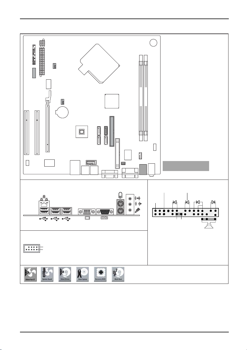
Mainboard D2660 - Internal c on necto
rs and slots
Additional power supply
Front panelPower supply
PCI 2
PCI 1
Fan 1
Power supply
Fan 2
PCI e x16
LAN
External connectors rear
USB dual channel
1
2
Battery
SATA 0 SATA 1
USB
1 = VCC AUX
2 = VCC AUX
3 = Data negative Port X
4 = Data negative Port Y
5 =
Data positive Port X
IDE
SATA 3
SATA 2
Floppy disk drive
Intrusion
6 = Data positive Port Y
7 =
GND
8 = GND
9 = Key
10 = Not connected
Buzzer
Memory Slot 2 Channel B
Memory Slot 1 Channel A
Audio
Audio
Frontpanel
Super I/O
Optionale Komponenten /
Optional components
Front panel
Power On/Off
Reset
1)
HD-LED
Message LED
Recovery Password
1) Both connector positions possible
2) 2pin or 3pin connector possible
Recovery inserted = The system starts
from floppy and allows a BIOS recovery
Password inserted = System- and BIOS
Password are skipped when device is
switched on
Power On
LED
Speaker
Sleep
2)
LED
1
2
A26361-D2660-Z110-1-8N19, edition 1
A26361-D2660-Z140-1-7619
Page 6
Mainboard D2660
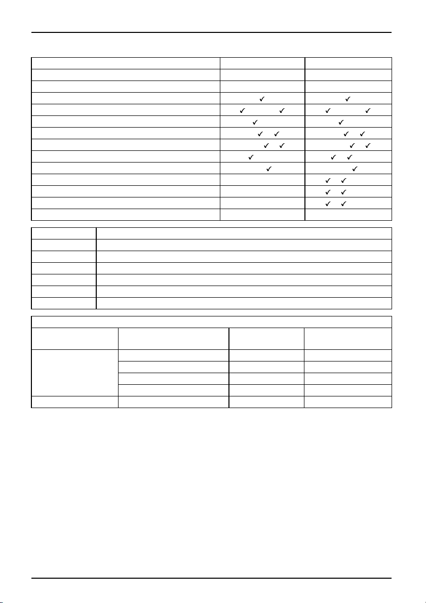
Chipset
Board size
Features D2660 A
Intel 946 GZ Intel 946 GZ
µBTX µBTX
D2660 C
VGA
Audio / 8-ch annel /S/PDIF /HDA /-/-/ /-/-/
Buzzer / int. Speaker Support
/- /LAN 1 Gbit / 100 Mbit/ 10 Mbit - / / -/ /
LAN ASF / Aol / WoL / Boot - / - / / -/-/ /
SATA / PATA / RAID /-/- / /FireWireTM / USB 2.0 - / -/
FAN monitored FAN1/FAN2/FAN3/FAN4 - / - / - / - / /-/FAN controlled FAN1/FAN2/FAN3/FAN4 - / - / - / - / /-/TEMP monitored CPU /Inside / System / HDD
SmartCard SystemLock (USB)
Silent Fan LT
Independent temperature related processor and fan supervision and control
-/-/-/-
--
/ /-/-
System Guard View and adjust Silent Fan LT
Silent Drives
Recovery BIOS
Desk Upda te
Multi Boot
HDD Passwort
Noise reduction for optical and hard disk drives
Restores a corrupted BIOS
Simple driver update with DU CD
Comfortable boot from any boot device
Access protection for ATA5/ATAPI5 disk drives
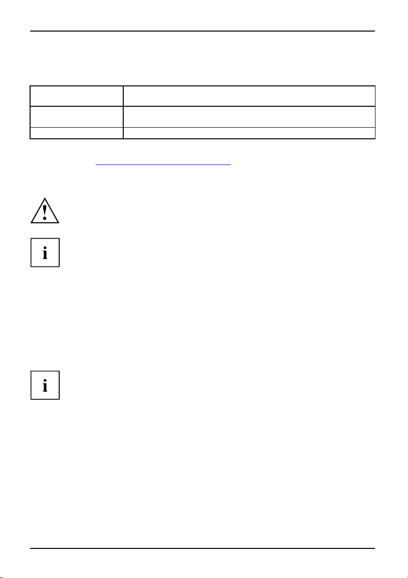
Power Supply Requirements - for onboard components (worst case)
Source
Main Power Supply
Aux. Power Supply
Voltag e
+12V
–12V
+5V
+3.3V
Maximal variation
+/–5%
+ / – 10%
+/–5%
+/ – 5 %
+5V +/–5%
Mainboard curr
Typical (Maxim
5.0 A (12.0 A)
0.01 A (0.01 A)
4.0 (8.0 A)
0.5 A (1.0 A)
0.5 A (0.5 A)
ent
al)
A26361-D2660-Z110-1-8N19, edition 1
Page 7
Kurzbeschreibung des Mainboards
Kurzbeschreibung des Mainboa
Hinweise zu den Baugruppen
Beachten Sie bei Baugruppen mit EGB unbedingt Folgendes:
• Sie müssen sich statisch entladen (z. B. durch Berühren eines geerdeten
Gegenstands), bevor Sie mit Baugruppen arbeiten.
• Verwendete Geräte und Werkzeuge müssen frei von statischer Aufladung sein.
• Ziehen Sie den Netzstecker, bevor Sie Baugruppen stecken oder ziehen.
• Fassen Sie die Baugruppen nur am Rand an.
• Berühren Sie keine Anschluss-Stifte oder Leiterbahnen auf der Baugruppe.
Eine Übersicht der Leistungsmerkmale finden Sie im Datenblatt.
Besondere Merkmale
Ihr Mainboard ist in verschieden en Ausbaustufen erhältlich. Abhängig von der Konfigurat ion
Ihres Mainboards besitzt oder unterstützt das Mainboard bestimmte Merkmale.
In diesem Handbuch finden Sie die wichtigsten Eigenschaften dieses Mainboards beschrieben.
Weitere Info rmationen zu Mainboards finden Sie im Handbuch "Basisinformationen Mainboard"
auf der CD "User Documentation" oder "OEM Mainboard" bzw. im Internet.
rds
Anschlüsse und Steckverbinder
Die Position der Anschlüsse und Steckverbinder Ihres Mainboards finden
Sie am Anfang des Handbuches.
Die markierten Komponenten und Steckverbinder müssen nicht auf
dem Mainboard vorhanden sein.
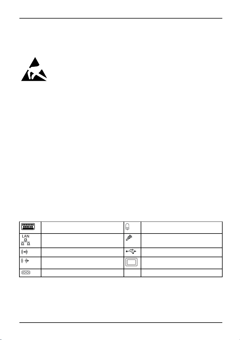
Externe Anschlüsse
Die Position der externen Anschlüsse Ihres Mainboards finden Sie am Anfang des Handbuches.
PS/2-Tastaturanschluss,
(optional)
LAN-Anschluss (RJ-45) Mikrofonanschluss, rosa
Audioeingang (Line in), h
Audioausgang (Line out), hellgrün VGA, blau
Serielle Schnittstelle, türkis
A26361-D2660-Z110-1-8N19, Ausgabe 1 Deutsch - 1
violett
ellblau
PS/2-Mausanschluss, grün
USB – Universal Serial Bus
(optional)
, schwarz
Page 8
Kurzbeschreibung des Mainboards
Prozessor ein-/ausbauen
Für alle hier beschriebene n Arbeiten muss Ihr System vollständig von der Netzspannung
getrennt sein! Nähere Angaben dazu finden Sie in der Betriebsanleitung Ihres Systems.
Technische Daten
• Intel Core Duo mit 800 oder 1066 MHz Front Sie B us in der Bauform LGA775
• Intel Pentium 4 / Int el Pentium D mit 533/800 MHz Front Side Bus (FMB05A,
max. 95 W) in der Bauform LGA775
• Intel Celeron D mit 533 MHz Front Side Bus in der Bauform LGA775
• Eine aktuelle Liste der von diesem Mainboard unt erstützten Prozessoren finden Sie
im Internet unter: "
Fassen Sie auf keinen Fall die Unterseite des Prozessors an. Schon leichte
Verunreinigungen wie Fett von der Haut können die Funktion des Prozessors
beeinträchtigen oder den Prozessor zerstören. Setzen Sie den Prozessor mit
großer Sorgfalt in den Steckplatz, da die Fed e rkontakte des Steckplatzes sehr
empfindlich sind und nicht verbogen werden dürfen.
Sind ein oder mehrere Federkontakte verbogen, setzen Sie auf keinen Fall
den Prozessor ein, da dieser dadurch beschädigt werden könnte. Wenden
Sie sich bitte direkt an Ihren zuständigen Händler
www.fujitsu-siemens.com/mainboards".
2 - Deutsch A26361-D2660-Z110-1-8N19, Ausgabe 1
Page 9
Vorgehensweise
Der Steckplatz für Prozessor ist zum Schutz der F ederkontakte mit einer Schutzkappe
abgedeckt. Im Garantiefall kann das Mainboard nur mit befestigter Schutzkappe
von Fujitsu Siemens Computers zurück genommen werden!
b
b
Kurzbeschreibung des Mainboards
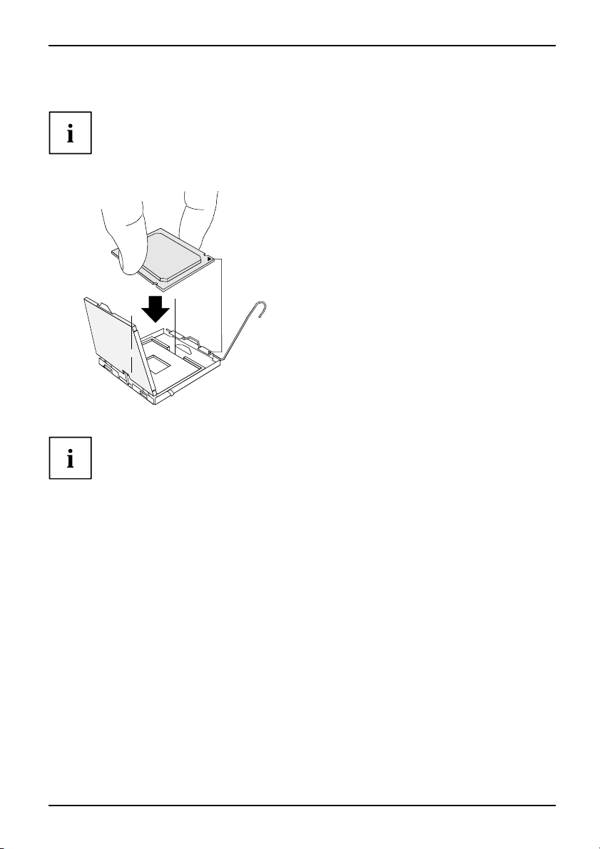
► Entfernen Sie den Kühlkörper.
► Drücken Sie auf den Hebel und
haken Sie ihn aus.
► Klappen Sie die Halterung nach oben.
► Halten Sie den Prozessor mit Daumen
und Z eigefinger und stecken Sie ihn
so in den Steckplatz (b), dass die
Markierung des Prozessors mit der
a
Markierung am Steckplatz von der Lage
her übereinstimmt (a).
► Drücken Sie den Hebel nach unten,
bis er wieder einhakt.
► Entfernen Sie die Schutzklappe und
verwahren Sie diese.
Bitte beachten S
Kühlkörperhalt
► Je nach Ausbau-Variante müssen Sie eine Schutzfolie vom Kühlkörper abziehen oder den
Kühlkörper mit W ärmeleitpaste bestreichen, bevor Sie ihn aufsetzen.
► Befestigen Sie d
oder stecken Sie
A26361-D2660-Z110-1-8N19, Ausgabe 1 Deutsch - 3
ie, dass je nach verwendetem Kühlkörper unterschiedliche
erungen auf dem Mainboard benötigt werden.
en Kühlkörper - je nach Ausführung - mit vier Schrauben
ihn in die Befestigungen.
Page 10
Kurzbeschreibung des Mainboards
Hauptspeicher e in-/ausbauen
Technische Daten
Technologie
Gesamtgröße 256 MBytes bis 4 GB yte
DDR2 533 / DDR2 667 ungepufferte DIMM Module 240-Pin; 1,8 V; 64
Bit, ohne ECC
Modulgröße
Eine aktuelle Liste der für dieses Mainboard empfohlenen Speichermodule finden Sie
im Internet unter: "
Es muss mindestens ein Speichermodul eingebaut sein. Speichermodule mit
unterschiedlicher Speicherkapazität können kombiniert werden.
Es d ürfen nur ungepufferte 1,8 V-Speichermodule ohne ECC verwendet werden.
DDR2-Speichermodule müssen der PC2-4200U- oder PC2-5300 U
-Spezifikation entsprechen.
Bei einer Speicherkonfiguration von 4 Gbyte kann der sichtbare und
benutzbare Hauptspeicher bis auf 3 Gbyte reduziert sein (abhängig
von der Konfiguration des Systems)
Der Ein-/Ausbau ist im Handbuch "Basisinformationen Mainboard" beschrieben.
256, 512, 1024 oder 2048 MByte pro Modul
www.fujitsu-siemens.com/mainboards".
PCI-Bus-Interrupts - Auswahl des richtigen PCI-Steckplatzes
Umfangreiche Informationen zu diesem Abschnitt finden Sie im H andbuch
"Basisinformationen Mainboard".
Um optimale Stabilität, Performance und Kompatibilität zu erreichen, vermeiden
Sie die mehrfache Nutzung von ISA IRQs oder PCI I RQ Lines (IRQ Sharing).
Sollte IRQ Sharing nicht zu umgehen sein, so müssen alle beteiligten Geräte
und deren Treiber IRQ Sharing unterstützen.
Welche ISA IRQs den PCI IRQ Lines zugeordnet werden, wird normalerweise automatisch
vom BIOS festgelegt (siehe Beschreibung "BIOS-Setup").
Monofunktionale Erweiterungskarten
PCI-/PCI-Express-Erweiterungskarten benötigen maximal einen Interrupt, der als
PCI-Interrupt INT A bezeichnet wird. Erweiterungskarten, die keinen Interrupt benötigen,
können in einen beliebigen Steckplatz eingebaut werden.
4 - Deutsch A26361-D2660-Z110-1-8N19, Ausgabe 1
Page 11
Kurzbeschreibung des Mainboards
Multifunktionale Erweiterungskarten od er Erweiterungskarten mit integrierter PCI-PCI Brigde
Diese Erweiterungskarten benötigen bis zu vier PCI-Interrupts: INT A, INT B, INT C, INT D.
Wie viele und welche dieser Interrupts verwendet werden, entnehmen Sie der
mitgelieferten Dokumentation der Karte.
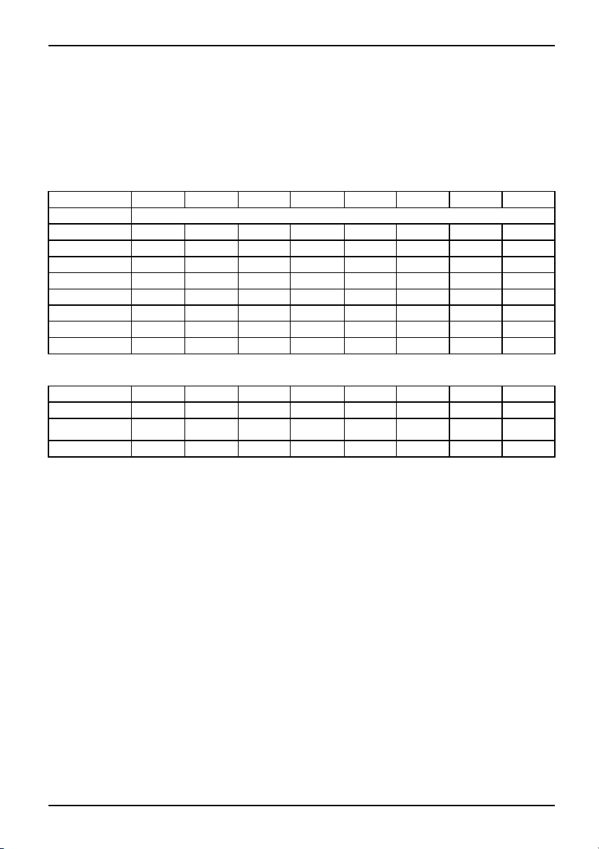
Die Zuordnung der PCI-Interrupts zu den IRQ Lines finden Sie in der folgend en Tabelle:
On board c ontroller
PCI INT LINE
1(A) 2(B) 3(C) 4(D) 5(E) 6(F) 7(G) 8(H)
USB 1.1
st
USB 2.0
SMBus
HD Audio
LAN
1
2
3
4
-------
nd
------
rd
-----
th
----
x
x
---
x
--
-------
---
--
x
---
x
---x
----
----
x
-
x
x
Mechanical Slot
PCI INT LINE
PCIe x16 AB
PCI 1
PCI 2
1(A) 2(B) 3(C) 4(D) 5(E) 6(F) 7(G) 8(H)
------
--
--
DC
CD
-
-
BA
AB
-
-
Verwenden S ie zuerst PCI-/PCI-Express-Steckplätze, die über eine einzige PCI IRQ Line
verfügen (kein IRQ Sharing). Wenn Sie einen anderen PCI-/PCI-Express-Steckplatz mit IRQ
Sharing benutzen müssen, überprüfen Sie, ob die Erweiterungskarte IRQ Sharing mit den
anderen Geräten auf dieser PCI IRQ Line einwandfrei unterstützt. Auch die Treiber aller Karten
und Komponenten an dieser PCI IRQ Line müssen IRQ Sharing unterstützen.
A26361-D2660-Z110-1-8N19, Ausgabe 1 Deutsch - 5
Page 12
Kurzbeschreibung des Mainboards
BIOS-Update
Wann sollt e ein BIOS-Update durchgeführt werden?
Fujitsu Siemens Computers stellt neue BIOS-Versionen zur Verfügung, um die Kompatibilität
zu neuen Betriebssystemen, zu neuer Software oder z u neuer Hardware zu gew ährleisten.
Außerdem können neue BIOS-Funktionen integriert werden.
Ein BIOS-Update sollte auch immer dann durchgeführt werden, wenn ein Problem besteht,
das sich durch neue Treiber oder neue Software nicht beheben lässt.
Wo gibt es BIOS-Updates?
Im Internet unter "
www.fujitsu-siemens.com/mainboards" finden Sie die BIOS-Updates.
BIOS-Update unter DOS mit startfähiger
BIOS-Update-Diskette – Kurzbeschreibung
► Laden Sie die Update-Datei von unserer Internet-Seite auf Ihren PC.
► Legen Sie eine leere Diskette (1,44 MByte) ein.
► Führen Sie die Update-Datei aus (z. B. 2461103.EXE).
Es wird eine startfähige Update-Diskette erstellt. Lassen Sie diese Diskette im Laufwerk.
► Starten Sie den PC neu.
► Folgen Sie den Bildschirmanweisungen.
Detaillierte Informationen zum BIOS-Update unter DOS find en Sie im Handbuch
zum "BIOS-Setup" (CD "Drivers & Utilities").
BIOS-Update unter Windows m
it dem
Utility DeskFlash
Ein BIOS-Update kann mit d
DeskFlash befindet sich au
6 - Deutsch A26361-D2660-Z110-1-8N19, Ausgabe 1
em Utility DeskFlash auch direkt unter Windows durchgeführt werden.
f der CD "Drivers & Utilities" (unter DeskUpdate).
Page 13

Brief description of mainboard
Brief description of mainboar
Information about boards
Be sure to observe the following for boards with ESD:
• You must always discharge static build up (e.g. by touching a grounded object)
before working.
• The equipm ent and tools you use must be free of static charges.
• Remove the power plug from the mains s upply before inserting or removing
boards.
• Always hold boards by their edges.
• Never touch pins or conductors on boards.
An overview of the fe atures is provided in the data sheet.
Special features
Your mainboard is available in different configuration levels. Your mainboard is equipped
with or supports particular features depending on the configuration.
This manual describes the most important properties of this mainboard.
Additional information on mainboards can be found in the "Basic information on mainboard"
manual on the "User Documentation" or "OEM Mainboard" CD or on the website.
d
Interfaces and connectors
The location of the interf
at the beginning of the man
The components and conne ct
aces and connectors of your mainboard is specified
ual.
ors marke d are not necessarily present on the mainboard.
External ports
The location of the extern
PS/2 keyboard port, violet (optional) PS/2 mouse port, green (optional)
LAN port (RJ-45) Microphone jack (mono), pink
Audio input (Line in), light blue USB – Universal Serial Bus, black
Audio output (Line out),
Serial interface, turq u
A26361-D2660-Z110-1-8N19, edition 1 English - 1
al connections of your mainboard is specified at the beginning of the manual.
light green
oise
VGA, blue
Page 14

Brief description of main board
Installing/removing the processor
Disconnect the system from the mains voltage before performing any of the tasks
described below. Details are contained in the operating manual of your system.
Technical data
• Intel Core Duo with 800 or 10 66 MHz front side bus in the LGA775 format
• Intel Pentium 4 / Intel Pentium D with 533/800 MHz front side bus (FMB05A,
max. 95 W ) in the LGA775 format
• Intel Celeron D with 533 MHz Front Side Bus in the LGA775 format
• A current list of the processors supported by this m ainboa rd is available on the
Internet at: "
www.fujitsu-siemens.com/mainboards".
Never touch the underside of the processor. Even minor soiling such as grease
from the skin can impair the processor’s operation or destroy the processor.
Place the processor in the socket with extreme care, as the spring contacts
of t he socket are very delicate and must not be bent.
If one or more spring contacts are bent, on no account insert the processor as it
may be damaged by doing so. Please contact the responsible vendor.
2 - English A26361-D2660-Z110-1-8N19, edition 1
Page 15

Procedure
The processor socket is covered with a protective cap to protect the spring
contacts. In the event of a warranty claim, the mainboard can only be taken back
by Fujitsu Siemens Computers with the protective cap secured!
b
Please note that, depending on the heat sink used, different heat sink
mounts are required on the mainboard.
Brief description of mainboard
► Remove the heat sink.
► Press down the lever and unhook it.
► Fold up the fra m e .
► Hold the processor between your thumb
and index finger and insert it into the socket
(b) so that the marking of the processor is
aligned with the marking on the socket (a).
b
a
► Press the lever downward until it is
hooked in again.
► Removetheprotectivecapandkeepit.
► Depending on the configuration variant, you must pull a protective foil off the heat sink
or coat the heat sink with heat conducting paste before fitting it.
► Secure the heat sink - depending on the model - with four screws or push it into the mounts.
A26361-D2660-Z110-1-8N19, edition 1 English - 3
Page 16

Brief description of main board
Installing/removing main memory
Technical da ta
Technology
Total Size 256 MB to 4 GB
Granularity 256, 512, 1024 or 2048 MB for one s
DDR2 533 / DDR2 667 unbuffered DIMM modules 240-pin; 1.8 V; 64
bit, no ECC
ocket
A current list of the memory modules recommended for this mainboard is availa ble
on the Internet at: "
At least one memory module must be installed. Memory modules with different
memory capacities can be combined.
You may use only unbuffered 1.8 V memory modules without ECC.
DDR2-memory modules must meet the PC2-4200U or PC2-5300U specification.
With a memory configuration of 4 GB the visible and usable main memory can
be reduced to 3 GB (depending on the system configuration).
The installation/removal is described in the "Basic information on mainboard" manual.
www.fujitsu-siemens.com/mainboards".
4 - English A26361-D2660-Z110-1-8N19, edition 1
Page 17

Brief description of mainboard
PCI bus interrupts - Selecting correct PCI slot
Extensive information on this section is contained in the manual "Basic information on mainboard".
To achieve optimum stability, performance and compatibility, avoid the multiple use
of ISA IRQs or PCI IRQ Lines (IRQ sharing). Should IRQ sharing be unavoidable,
then all involved devices and their drivers must support IRQ sharing.
Which ISA IRQs are assigned to the PCI IRQ Lines is normally automatically
specified by the BIOS (see "BIOS Setup" description).
Monofunctional expansion cards
PCI/PCI Express expansion cards require a maximum of one interrupt, which is called the PCI
interrupt INT A. Expansion cards that do not require an interrupt can be inst alled in any desired slot.
Multifunctional expansion cards or expansion cards with integrated PCI-PCI bridge
These expansion cards require up to four PCI interrupts: INT A, INT B, INT C, INT D. H ow many
and which of these interrupts are used is specified in the documentation provided with the card.
The assignment of the PCI interrupts to the IRQ Lines is shown in the following table:
On board c ontroller
PCI INT LINE 1 (A) 2 (B) 3 (C) 4 (D) 5 (E) 6 (F) 7 (G) 8 (H)
USB 1.1
USB 2.0
SMBus
HD Audio
LAN
st
1
2
3
4
-------
nd
------
rd
-----
th
----
x
x
---
x
--
-------
---
--
x
---
x
---x
----
----
x
-
x
x
Mechanical slot
PCI INT LINE 1 (A) 2 (B) 3 (C) 4 (D) 5 (E) 6 (F) 7 (G) 8 (H)
PCIe x16
PCI 1
PCI 2
AB
--
--
First use PCI/PCI Expres
must use another PCI/PCI
properly supports IRQ s
haring with the other devices on this PCI IR Q Line. The drivers of all
cards and components on
s slots that have a single PCI IRQ Line (no IRQ sha ring). If you
Express slot with IRQ sharing, check whether the expansion card
this PCI IRQ Line must also support IRQ sharing.
------
D
C
CD
-
-
BA
AB
-
-
A26361-D2660-Z110-1-8N19, edition 1 English - 5
Page 18

Brief description of main board
BIOS Update
WhenshouldaBIOSupdatebecarriedout?
Fujitsu Siemens Co mputers makes new BIOS versions available to ensure
compatibility with new operating systems, new software or new hardware. In
addition, new BIOS functio ns can also be integrated.
A BIOS update should also always be carried out when a problem exists that
cannot be solved with new drivers or new software.
Where can I obtain BIOS updates?
The BIOS updates a re available on the Internet at "
www.fujitsu-siemens.com/mainboards".
BIOS update under DOS with bootable BIOS
update floppy disk - brief description
► Download the update file from our website to your PC.
► Insert an empty floppy disk (1.44 Mbyte).
► Run the update file (e.g. 2461103.EXE).
A bootable update floppy disk is created. Leave this floppy disk in the drive.
► Restart the PC.
► Follow t he instructions on screen.
Detailed information on the BIOS update under DOS is provided in the
"BIOS Setup" manual ("Drivers & Utilities" CD).
BIOS update under Windows wi
A BIOS update can also be carried out directly under Windows with the DeskFlash utility.
DeskFlash can be found on the "Drivers & Utilities" CD (under DeskUpdate).
6 - English A26361-D2660-Z110-1-8N19, edition 1
th DeskFlash utility
Page 19

Brève descriptio n de la carte m ère
Brève description de la carte m
Remarques relatives aux cartes
Respectez impérativement les consignes suivantes avec les cartes équipées de
composants sensibles à l’électricité statique :
• Vous devez vous décharger de l’électricité statique (en touchant un objet relié à
la terre, par exemple) avant de manipuler les cartes.
• Les appareils et outils uti
• Débranchez les câbles avant de connecter ou de déconnecter les cartes.
• Manipulez les cartes en les t
• Evitez de toucher les broches ou les circuits d’une carte.
Vous trouverez un aperçu des caractéristiques de performances dans la fiche technique.
Caractéristiques
Votre carte mère est disponible en plusieurs niveaux d’équipement. Suivant sa configuration,
votre carte mère possède ou suppor te certaines caractéristiques.
Vous trouverez dans ce manuel une description des principales caractéristiques de cette carte mè re.
Vous trouverez d’autres informations sur les cartes mères dans le manuel "Basisinformationen
Mainboard" sur le CD "User Docume ntation" ou "OEM Mainboard" ainsi que sur Internet.
lisés doivent être d épourvus de toute charge statique.
enant uniquement par leurs bords.
ère
Ports et connecteurs
Au début du manuel vous trouverez la position des ports et des connecteurs sur votre carte mère.
Les composants et conne cteurs marqués ne sont pas obligatoirement
disponibles sur la carte mère.
Ports externes
Au début du manuel, vous trouverez la position des ports externes de votre carte mère.
Port clavier PS/2, violet (en option) Port souris PS/2, vert (en option)
Port LAN (RJ-45)
Entrée audio (Line in), bleu ciel USB – Universal Serial Bus, noir
Sortie audio (Line out), vert c la ir VGA, bleu
Interface série, turquoise
A26361-D2660-Z110-1-8N19, édition 1 Français - 1
Port microphone, rose
Page 20

Brève description de la carte mère
Monter/démonter le processeur
Avant de procéder aux étapes décrites ci-après, il est indispensable de séparer
intégralement votre système de la tension de secteur ! Vous trouverez à ce propos
d’autres indications détaillées dans le manuel de votre système.
Caractéristiques techniques
• Intel Core Duo avec bus front
• Intel Pentium 4 / Intel Pentium D avec bus frontal 533/800 MHz (FMB05A,
max. 95 W) en configuration LGA775
• Intel Celeron D avec bus bus fr
• Vous trouverez une liste actualisée des processeurs supportés par cette carte mère sur
Internet à l’adresse suivante : "
Ne touchez jamais la face inférieure du processeur. De légères salissures comme le
gras de la peau peuvent perturber le fonctionnement du processeur ou le détruire.
Usez de la plus grande précaution pour insérer le proce sseur dans le logement : les
contacts à ressort du logement sont très sensibles et il ne faut pas les plier.
Si l’un ou plusieurs des co ntacts à ressort sont pliés, n’insérez en
aucun cas le processeur dans le logement sous peine de l’endommager.
Adressez-vous directement à votre revendeur
al 800 ou 1066 MHz en configuration LGA 775
ontal 533 MHz en configuration LGA775
www.fujitsu-siemens.com/mainboards".
2 - Français A26361-D2660-Z110-1-8N19, édition 1
Page 21

Méthode
Le logement réservé au processeur comporte un couvercle qui sert à protéger les
contacts à ressort. En cas de garantie, la carte mère (Mainboard) sera uniquement
acceptée par Fujitsu Siemens Computers si le couvercle de protection est en place !
Veuillez tenir compte du fait que les clips de fixation du refroidisseur nécessaires
sur la carte mère varient en fonction du type de refroidisseur utilisé.
Brève descriptio n de la carte m ère
► Retirez le refroidisseur.
► Appuyez sur le levier et décrochez-le.
► Relevez le support vers le ha
► Saisissez le processeur entre le pouce et
l’index et insérez-le dans le logement (b)
de sorte que de l’encoche du processeur
coïncide avec l’encoche sur le logement (a).
b
b
a
► Rabaissez le levier jusqu’à
s’enclenche.
► Retirez le capot protecteur et conservez-le.
ut.
ce qu’il
► Suivant le modèle, vous de vez soit retirer un film de protection du refroidisseur soit en duire
le refroidisseur d’une pâte conductrice de chaleur avant de le remonter.
► Fixez le refroidisseur – suivant le modèle – à l’aide de quatre vis ou enfichez-le dans les fixations.
A26361-D2660-Z110-1-8N19, édition 1 Français - 3
Page 22

Brève description de la carte mère
Monter/démonter le processeur
Caractéristiques techniques
Technologie
Taille totale
Taille du module 256, 512, 1024 ou 2048 Mo par module
Modules DIMM DDR2 533 / DDR2 667 sans tampon 240 broches ;
1,8 V; 64 bits, sans CCE
256 Mo jusqu’à 4 Go
Vous trouverez une liste act
cartemèresurInternetàl’a
Au moins un module d’extensi
des modules d’extension mém
Vous ne pouvez utiliser que
Les modules d’extension m
spécification PC2-4200U
Dans le cas d’une configuration mémoire de 4 Go, la mémoire visible et utilisable
peut être réduiteà3Gomaximum(selonlaconfiguration du système)
Le montage/démontage est décrit dans le manuel "Basic information on mainboard".
ualisée des modules d’extension mémoire recommandés pour cette
dresse suivante : "
on mémoire doit être monté. Il est possible de combiner
oire de capacités différentes.
ou PC2-5300U.
www.fujitsu-siemens.com/mainboards".
des modules mémoires 1,8 V sans tampon sans CCE.
émoire DDR2 doivent être conformes à la
Interruptions du BUS PCI - Sélection du logement PCI adéquat
Vous trouverez de plus amples informations sur ce chapitre dans le manuel
"Basic informa tion on mainboard".
Afin d’obtenir une stabilité, des performances et une compatibilité optimales,
évitez l’utilisation multiple de lignes IRQ ISA ou IRQ PCI (IR Q Sharing).
Si l’IRQ Sharing est inévitable, tous les périphériques impliqués et leurs
pilotes doivent supporter l’IRQ Sharing.
L’affectation des IRQ ISA aux lignes IRQ PCI est normalement fixée automatiquement
par le BIOS (voir description "Setup du BIOS").
Cartes d’extension monofonctionnelles
Les cartes d’extension PCI/PCI Express requièrent tout au plus une interruption, désignée
comme interruption PCI INT A. L es cartes d’extension ne nécessitant aucune interruption
peuvent être montées dans n’importe quel logement.
Cartes d’extension multifonction ou cartes d’extension avec pont PCI-PCI intégré
Ces cartes d’extension nécessitent jusqu’à quatre interruptions PCI : INT A, INT B,
INT C, INT D. Pour savoir combien et lesquelles de ces interruptions sont utilisées,
reportez-vous à la documentation fournie avec la carte.
4 - Français A26361-D2660-Z110-1-8N19, édition 1
Page 23

Brève descriptio n de la carte m ère
L’affectation des interruptions PCI aux lignes IRQ est reprise dans le tableau suivant :
On board c ontroller
PCI INT LINE 1 (A) 2 (B) 3 (C) 4 (D) 5 (E) 6 (F) 7 (G) 8 (H)
USB 1.1
st
1
2
3
4
USB 2.0
SMBus
HD Audio
LAN
-------
nd
------
rd
-----
th
----
x
x
---
-------
---
--
x
---
x
---x
----
----
x
--
Mechanical Slot
PCI INT LINE 1 (A) 2 (B) 3 (C) 4 (D) 5 (E) 6 (F) 7 (G) 8 (H)
PCIe x16
PCI 1
PCI 2
AB
--
--
------
D
C
CD
-
-
BA
AB
x
-
x
x
-
-
Utilisez d’abord les logeme
(pas d’IRQ Sharing). Si vou
Sharing, vérifiez si la cart
périphériques sur cette li
cette ligne IRQ PCI doiven
nts PCI/PCI Express qui disposent d’une seule ligne IRQ PCI
s devez utiliser un autre logement PCI/PCI Express avec IRQ
e d’extension supporte intégralement l’IRQ Sharing avec les autres
gne IRQ PC I. Les pilotes d e toutes les cartes et composants de
t également supporter l’IRQ Sharing.
A26361-D2660-Z110-1-8N19, édition 1 Français - 5
Page 24

Brève description de la carte mère
MiseàjourduBIOS
Quand une mise à jour du BIOS est-elle nécessaire ?
Fujitsu Siemens Computers propo se de nouvelles versions du BIOS afin de garantir la compatibilité
avec les nouveaux systèmes d’exploitation, les nouveaux logiciels ou le n ouveau matériel.
De nouvelles fonctionnalités du BIOS peuvent en outre être intégrées.
Une mise à jour du BIOS est toujours nécessa ire en cas de problème ne pouvant
être résolu par l’utilisation de nouveaux pilotes ou logiciels.
Où se procurer des mises à jour du BIOS ?
Les mises à jour du BIOS sont disponibles sur Internet à l’adresse "
www.fujitsu-siemens.com/mainboards".
Mise à jour du BIOS sous DOS avec disquette de mise
à jour du BIOS opérationnelle – Brève description
► De notre page Internet, téléchargez sur votre PC le fichier de mise à jour.
► Introduisez une disquette vierge (1,44 Moctets).
► Lancez l’exé cution du fichierdemiseàjour(p.ex.:2461103.EXE).
Une disquette amorçable de mise à jour est créée. Laissez cette disquette
dans le lecteur de disquettes.
► Redémarrez le PC.
► Suivez les instructions à l’écran.
Vous trouverez des informations déta illées sur la mise à jour du BIO S sous
DOS dans le m anuel "BIOS-Setup" (CD "Drivers & Ut ilities").
MiseàjourduBIOSsousWin
dows avec
l’utilitaire DeskFlash
Le BIOS peut également êtr
DeskFlash se trouve sur l
6 - Français A26361-D2660-Z110-1-8N19, édition 1
e mis à jour directement sous Windows avec l’utilitaire DeskFlash.
e CD "Drivers & Utilities" (sous DeskUpdate).
Page 25

Краткое описание материнской платы
Краткое описание материнской
Указания по модулям
Для модулей с EGB обязательно учитывайте следующее:
• Перед работой с модулями требуется статически разрядить свое тело
(например посредством касания какого-либо заземлённого предмета).
• Исключить возможность статического заряда используемых устройств
иинструментов.
• Перед установкой или снятием модулей выньте вилку сетевого кабеля
из розетки.
• Касайтесь только кромок модулей.
• Не прикасайтесь к штырьковым выводам или печатным проводникам
модуля.
Обзор производственных показателей Вы найдёте в техническом паспорте.
Отличительные особенности
Вы можете приобрести материнскую плату в различных конфигурационных
исполнениях. Ваша материнская плата в зависимости от своей конфигурации
обладает определенными признаками или поддерживает их.
В этом Руководстве по эксплуатации Вы найдете описание важнейших
свойств этой материнской платы.
Дальнейшую информацию о материнских платах Вы найдёте в руководстве
"Basisinformationen Mainboard" ("Основная информация о материнской плате") на
компакт-диске "User Documentation" (Пользовательская документация) или "OEM
Mainboard" (Материнская плата OEM) или в Интернете.
платы
A26361-D2660-Z110-1-8N19, издание 1 Pycckuй -1
Page 26

Краткое описание материнской платы
Порты и штекерные разъемы
Информацию о расположении портов и штекерных разъемов на Вашей материнской
плате Вы найдете в начале Руководства по эксплуатации.
Помеченные компоненты и штекерные разъемы могут отсутствовать на материнской
плате.
Внешние порты
Информацию о расположении внешних портов на Вашей материнской плате
ВынайдетевначалеРуководствапоэксплуатации.
Порт клавиатуры PS/2, фиолетовый
(опция)
Порт LAN (RJ-45)
Порт мыши PS/2, зеленый (опция)
Порт микрофона, розовый
Aудиовход (Line in), светло-синий USB – Universal Serial Bus
Аудиовыход (Line out), свет
зеленый
Последовательный интерфейс,
бирюзовый
ло-
Монтаж/демонтаж процессора
Для осуществления всех описанных здесь работ Ваша система должна быть
полностью отключена от сетевого напряжения! Более подробную информацию
об этом Вы найдете в руководстве по эксплуатации Вашей системы.
(универсальная последовательная
шина), черный
VGA, синий
2 - Pycckuй A26361-D2660-Z110-1-8N19, издание 1
Page 27

Краткое описание материнской платы
Технические данные
• Intel Core Duo с 800 или 1066 MГц Front Side Bus вконструкцииLGA775
• Intel Pentium 4 / Intel Pentium D с 533/800 MГц Front Side Bus (FMB05A,
макс.95Вт) вконструкцииLGA775
• Intel Celeron D с 533 MГц Front Side Bus вконструкцииLG A775
• Актуальный список процессоров, поддерживаемых этой материнской платой, Вы
найдетевИнтернетенасайте: "
Ни в коем случае не прикасайтесь к нижней стороне процессора. Даже
малейшие загрязнения, как например, жирнакоже, могут негативно
сказаться на работе процессора или повредить его. Устанавливайте
процессор в разъем очень осторожно, поскольку пружинные контакты
разъема очень чувствительны и их нельзя изгибать.
В том случае, если один или несколько пружинных контактов изогнуты,
ни в коем случае не устанавливайте процессор, поскольку из-за этого
он может быть поврежден. Пожалуйста, обратитесь непосредственно
к Вашему компетентному продавцу
www.fujitsu-siemens.com/mainboards".
A26361-D2660-Z110-1-8N19, издание 1 Pycckuй -3
Page 28

Краткое описание материнской платы
Способ действия
Разъем для процессора закрыт защитной пластинкой для защиты пружинных
контактов. В случае предъявления гарантийных претензий возвращаемая
материнская плата может быть принята только при наличии прикрепленной
защитной пластинки фирмы Fujitsu Siemens Computers!
b
b
a
► Удалите радиатор.
► Нажмите на рычаг и поднимите его.
► Поднимите устройство крепл
► Держите процессор большим и
указательным пальцами и вставьте его
вразъем(b) так, чтобы маркировка на
процессоре по своему расположению
полностью совпала с маркировкой
на разъеме (а).
► Нажмите на рычаг вниз до щ
означающего, что процес
► Удалите защитную пластинку и
сохраняйте ее.
ения вверх.
елчка,
сор закреплен.
Пожалуйста, уч
материнской пл
► В зависимости от варианта конфигурации перед установкой радиатора Вы должны снять
защитную пленку с радиатора, или же покрыть радиатор теплопроводящей пастой.
► Закрепите радиатор (в зависимости от конфигурации) припомощичетырех
шурупов или же вставьте его в крепеж.
4 - Pycckuй A26361-D2660-Z110-1-8N19, издание 1
итывайте то, что в зависимости от используемого радиатора на
ате требуются различные устройства крепления радиатора.
Page 29

Краткое описание материнской платы
Монтаж/демонтаж ОЗУ
Технические данные
Технология
Общий объем памяти От 256 мегабайтов до 4 гигабайтов
Объем памяти модулей 256, 512, 1024 или 2048 Mбнакажд
DDR2 533 / DDR2 667 модули DIMM без буферизации 240-Pin;
1,8 В;64бит, без ECC
ом модуле
Актуальный список модулей памяти, рекомендованных для этой материнской платы,
ВынайдетевИнтернетенасайте: "
Должен быть установлен хотя бы один модуль памяти. Можно комбинировать
модули памяти с различной ёмкостью ЗУ.
Допускается применение только модулей памяти без буферизации 1,8 ВбезECC.
Модули памяти DDR2 должны соответствовать спецификации
PC2-4200U или PC2-5300U.
При конфигурации памяти размером 4 Гбайта видимое и используемое ОЗУ может
быть сокращено до 3 Гбайтов (в зависимости от конфигурации системы)
Монтаж и демонтаж описаны в руководстве по эксплуатации "Basic information on
mainboard" ("Основная информация о материнской плате")..
www.fujitsu-siemens.com/mainboards".
Прерывания на шине PCI – выбор правильного разъёма PCI
Подробную информацию к этому разделу Вы найдете в руководстве "Basic information
on mainboard " ("Основная информация о материнской плате").
Для того, чтобы достичь оптимальной стабильности, рабочих характеристик
и совместимости, избегайте многократное использования ISA IRQ или PCI
IRQ Lines (IRQ Sharing). Если нельзя отказаться от механизма совместного
использования прерываний (IRQ Sharing), то все задействованные устройства
и их драйверы должны поддерживать IRQ Sharing.
Обычно BIOS автоматически назначает соответствующие ISA IRQ на PCI
IRQ Lines (см. описание "BIOS-Setup").
Монофункциональные расширительные платы
Для расширительных плат PCI-/PCI-Express требуется максимально одна линия
прерывания, которую называют прерыванием PCI INT A. Расширительные платы, не
требующие линий прерывания, можно встраивать в любой разъем.
A26361-D2660-Z110-1-8N19, издание 1 Pycckuй -5
Page 30

Краткое описание материнской платы
Многофункциональные расширительные платы или расширительные
платы со встроенным мостом PCI-PCI
Эти расширительные платы требуют до четырех PCI-прерываний: INT A, INT B, INT C,
INT D. Информацию о количестве прерываний и о том, какие из них используются,
Вы найдете в документации, поставляемой вместе с платой.
Назначение прерываний PCI на IRQ Lines Вы найдете в следующей таблице:
On board co nt roller
PCIINTLINE 1(A) 2(B) 3(C) 4(D) 5(E) 6(F) 7(G) 8(H)
USB 1.1
st
USB 2.0
SMBus
HD Audio
LAN
1
2
3
4
-------
nd
------
rd
-----
th
----
x
x
---
x
--
-------
---
--
x
---
x
---x
----
----
x
-
x
x
Mechanical Slot
PCIINTLINE 1(A) 2(B) 3(C) 4(D) 5(E) 6(F) 7(G) 8(H)
PCIe x16
PCI 1
PCI 2
AB
--
--
------
D
C
CD
-
-
BA
AB
-
-
Используйте сначала разъем
линией PCI IRQ (без механиз
другой разъем PCI-/PCI-E
что расширительная карт
устройствами на этой лин
на этой линии PC I IRQ долж
ы PCI-/PCI-Express, которые обладают лишь одной
ма IRQ Sharing). Если Вам нужно использовать
xpress смеханизмомIRQ Sharing, убедитесь в том,
а безукоризненно поддерживает IRQ Sharing сдругими
ии PCI IRQ. Также и драйверы всех плат и компонент
ны поддерживать IRQ Sharing.
6 - Pycckuй A26361-D2660-Z110-1-8N19, издание 1
Page 31

Краткое описание материнской платы
Обновление BIOS
Когда необходимо обновить BIOS?
Фирма Fujitsu Siemens Computers предоставляет в распоряжение пользователя новые
версии BIOS для того, чтобы обеспечить совместимость с новыми операционными
системами, с новым программным обеспечением или с новым техническим обеспечением.
Кроме того, имеется возможность для интеграции новых функций BIOS.
BIOS всегда необходимо обновлять также и в том случае, если имеется проблема, которую не
удается удалить за счет установки нового драйвера или нового программногообеспечения.
Где можно найти новые версии BIOS?
Вы найдете новые версии BIOS в Internet на сайте: "
www.fujitsu-siemens.com/mainboards".
Обновление BIOS в DOS при помощи
загрузочной дискеты с обновлённой версией
BIOS – краткое описание
► Скачайте файл с обновленной версией с нашего сайта в Internet на Ваш компьютер.
► Вставьте в дисковод пусту
► Запустите файл с обновленной версией (например, 2461103.EXE).
Так будет создана дискета
Оставьте дискету в дисков
► Перезагрузите ПК.
► Выполняйте указания, высв
юдискету(1,44 Мб).
начальной загрузки с обновленной версией.
оде.
ечивающиеся на дисплее.
Подробную информацию об о
руководстве "BIO S-Setup
бновлении BIOS в DOS Вы найдете в
"(компакт-диск "Drivers & Utilities").
Обновление BIOS в Windows с использованием утилиты DeskFlash
Обновление BIOS может быть также осуществлено с помощью утилиты
DeskFlash непосредственно под Windows. DeskFlash находится на компакт-диске
"Drivers & Utilities" (в разделе DeskUpdate).
A26361-D2660-Z110-1-8N19, издание 1 Pycckuй -7
Page 32

Краткое описание материнской платы
8 - Pycckuй A26361-D2660-Z110-1-8N19, издание 1
Page 33

Sistem yapı grubunun kısa tanıtımı
Sistem yapı grubunun kısa tanı
Yapı gruplarına ilişkin bilgiler
EGB’li yapı gruplarında mutlaka şunlara dikkat edin:
• Modüller ile çalışmadan önce kendinizdeki statik yüklenmeyi deşarj etmelisiniz
(örneğin topraklanmış bir cisime dokunarak).
•Kullanılan cihaz ve aletlerde statik yüklenme olmamalıdır.
• Modülleri yerleştirmeden veya çekmeden önce şebeke fişini prizden çekiniz.
• Modülleri yalnız kenarından tutunuz.
• Modülün üzerindeki bağlantı uçlarına veya iletkenlere dokunmayı n.
Performans özellikleriyle ilgili bir genel bakışı bilgi sayfasında bulabilirsiniz.
Özel karakteristikleri
Anakartınızçeşitli donanım k ade melerinde mevcuttur. Ana kartınızınkonfigürasyonuna
bağımlı olarak ana kartınız belirli özelliklere sahiptir veya destekler.
Bu anakartın önemli özellikleri bu el kitabı içinde açıklanmıştır.
Anakartlara ilişkin daha fazla bilgiyi "User Documentation" CD’si üzerindeki "Basisinformationen
Mainboard" El Kitabında veya "OEM Mainboard" ya da internette bulabilirsiniz.
tımı
Girişler ve soket bağlantısı
Ana kart girişlerinizinvesoketbağlantılarınızın konumunu el kitabınınbaşlangıcında bulabilirsiniz.
İşaretlenen parçalar ve soket bağlantıları ana kartta bulunmama lıdır.
Harici girişler
Ana kart harici girişlerinizin konumunu el kitabınınbaşlangıcında bulabilirsiniz.
PS/2 klavye girişi, mor (op
siyonel)
PS/2 fare girişi, mor (opsi
yonel)
LAN girişi(RJ-45) Mikrofon girişi, pembe
Ses girişi(giriş), açıkma
Ses çıkışı (çıkış), açı kyeşil VGA, mavi
Seri bağlantı noktası, turkuvaz
A26361-D2660-Z110-1-8N19, basım1 Türkçe-1
vi
USB – Üniversal seri veri yolu, siyah
Page 34

Sistem yapı grubunun kısa tanıtımı
İşlemcinin takılması/sökülmesi
Burada açıklanan tüm çalışma
olmalıdır! Bununla ilgili de
lar için sisteminiz tamamen ağ geriliminden ayrılmış
taylı bilgileri sisteminizin kullanımkılavuzunda bulabilirsiniz.
Teknik özellikler
• 1066 veya 800 MHz Front Side Bus’lı, LGA775 model Intel Core Duo
• 533/800 MHz Front Side Bus’lı (FMB05A, maks. 95 W), LGA775 model
Intel Pentium 4 / Intel Pentium D
• 533 MHz Front Side Bus’lı, LGA775 model Intel Celeron D
• Bu ana kart tarafından desteklenen işlemcilerin güncel bir listesini Internet’te şu
adreste bulabilirsiniz: "
Asla işlemcinin alt yüzüne dokunmayın. Derinizin üzerinde bulunan örneğin yağ
gibi hafif kirler dahi i şlemcinin çalışmasını olumsuz etkileyebilir veya işlemciyi tahrip
edebilir. İşlemci yuvasınınyaylı kontakları çok hassas olduğundan ve bükülmeleri
yasak olduğundan işlemciyi çok itinalı bir şekilde yuvasına oturtun.
Birveyabirdenfazlayaylı kontak bükülmüşse işlemciyi kesinlikle yerleştirmeyin, aksi
takdirde işlemciye h asar verilebilir. Lütfen direkt olarak yetkili satıcınıza başvurun
www.fujitsu-siemens.com/mainboards".
2 - Türkçe A26361-D2660-Z110-1-8N19, basım1
Page 35

Uygulama tarzı
İşlemcinin yuvası yaylı kontakların korunması için bir koruyucu kapakla örtülmüştür.
Garanti durumunda ana kart ancak koru yucu kapak sabit takılı olduğunda
Fujitsu Siemens Computers tarafından geri alınacaktır!
b
b
Anakart üzerinde, kullanılan soğutma bloğuna göre farklı soğutma bloğu
tutucularının gerekli olduğunu lütfen dikkate alın.
Sistem yapı grubunun kısa tanıtımı
► Soğutma bloğunu çıkarın.
► Mandalınüzerinebastırınve
yerinden çıkarın.
► Tutucuyu yukarı doğru katlayın.
►İşlemciyi başparmağınızveişaret
parmağınızla tutun ve işlemcinin işareti
yuvadaki işaretle örtüşecek (a) şekilde
işlemciyi yuvasının(b)içinetakın.
a
► Mandalı yerine geçinceye kadar
aşağıya bastırın.
► Koruyucu kapağı çıkarınvebunusaklayın.
► Sökme türüne göre bir koruyucu folyoyu soğutma gövdesinden çıkartmalı veya yerleştirmeden
önce soğutma gövdesine ısı iletken macunu sürmelisiniz.
► Soğutma bloğunu - modeline göre - dört cıvata ile tespit edin veya bağlantı yerlerine yerleştirin.
A26361-D2660-Z110-1-8N19, basım1 Türkçe-3
Page 36

Sistem yapı grubunun kısa tanıtımı
Ana belleğin takılması/sökülmesi
Teknik özellikler
Teknoloji
Toplam boyut
Modül boyutu Modül başına 256, 512, 1024 veya 2048 Mbayt
DDR2 533 / DDR2 667 tampon belleksiz DIMM modülleri 240-Pin;
1,8V;64Bit,ECC’siz
256 MByte’tan 4 GByte’a kadar
Bu ana kart için tavsiye edil
adreste bulabilirsiniz: "
En az bir hafıza modülü takıl
hafıza modülleri kombine ed
Yalnızca E C C’siz tampon be
DDR2 bellek modüllerinin
şarttır.
4 Gbyte olan bir bellek konfigürasyonunda görülebilen ve k ullanı la bilen ana bellek
3 Gbyte’a kadar azaltılmış olabilir (sistemin konfigürasyonuna bağımlıdır)
Takma/Sökme işlemi "Anakart Temel Bilgileri" el kitabı içinde açıklanmıştır.
en hafıza modüllerinin güncel bir listesini Internet’te şu
ww.fujitsu-siemens.com/mainboards".
w
mış olmalıdır. Çeşitli hafıza ka pasitesine sahip
ilebilir.
lleksiz 1,8 V bellek modüllerinin kullanılması serbesttir.
PC2-4200U- veya PC2-5200U spesifikasyonuna uygun olması
PCI-Bus-Interrupts - Doğru PCI yuvasının seçilmesi
Bu bölümle ilgili kapsamlı bilgileri "Basic information on mainboard" ("Anakart
Temel Bilgileri") el kitabı içinde bulabilirsiniz.
Optimal stabilite, performans ve uyumluluğu elde etmek için ISA IRQ’larınveyaPCIIRQ
Line’ların çoklu kullanımından (IRQ Sharing) kaç ının. IRQ paylaşımı önlenemiyorsa,
tüm katılımcı cihazlar ve bunların sürücüleri IR Q paylaşımını desteklemelidir.
PCI IRQ Line’larına hangi ISA IRQ’ların tayin edileceği normalde BIOS tarafından
otomatik olarak belirlenir (bkz. "BIOS-Setup" açıklaması).
Tekli fonksiyonel geliştirme kartları
PCI-/PCI-Express geliştirme kartları PCI-Interrupt INT A olarak tanımlanan maksimum bir In terrupt
gerektirmektedir. Interru pt gerektirmeyen geliştirme kartları istenilen bir yere takılabilir.
Çok fonksiyonlu genişletme kartları veya entegre PCI-PCI köprülü genişletme kartları
Bu geliştirme kartları dört PCI-Interrupt‘a kadar ihtiyacı vardır: INT A, INT B, INT C , INT D. Bu
Interrupt’ların kaç sayıda ve hangilerinin kullanılacağı gönderilen kartların belgesinden alabilirsiniz.
Hangi PCI-Interrupt’ın hangi IRQ Line’lar
4 - Türkçe A26361-D2660-Z110-1-8N19, basım1
ına ait olduğuaşağıdaki tabloda gösterilmiştir:
Page 37

Sistem yapı grubunun kısa tanıtımı
On board c ontroller
PCI INT LINE 1 (A) 2 (B) 3 (C) 4 (D) 5 (E) 6 (F) 7 (G) 8 (H)
USB 1.1
st
1
2
3
4
USB 2.0
SMBus
HD Audio
LAN
-------
nd
------
rd
-----
th
----
x
x
---
-------
---
--
x
---
x
---x
----
----
x
--
Mechanical slot
PCI INT LINE 1 (A) 2 (B) 3 (C) 4 (D) 5 (E) 6 (F) 7 (G) 8 (H)
PCIe x16
PCI 1
PCI 2
AB
--
--
------
D
C
CD
-
-
BA
AB
x
-
x
x
-
-
Öncelikle tek bir PCU IRC hatt
paylaşımı yok). IRQ paylaşım
zorundaysanız, gelişmiş k
kusursuzca desteklenip d
kartlarınveparçalarıns
artlara ait IRQ paylaşımınındiğer cihazlarla bu PCI IRC hattında
esteklenmediğini kontrol edin. Bu PCI IRC hattındaki tüm
ürücüleri IRQ paylaşımını desteklemelidir.
ına sahip olan P CI-/PCI-Express yerlerini kullanın(IRC
ı olan başka bir PCI-/PCI-Express yerlerini kullanmak
A26361-D2660-Z110-1-8N19, basım1 Türkçe-5
Page 38

Sistem yapı grubunun kısa tanıtımı
BIOS-Update (Güncelleştirme)
Ne zaman bir BIOS-Update yapılmalıdır?
Yeni işletim sistemlerine, yeni yazılımlara veya yeni donanımlara uyumluluğu garantilemek
için Fujitsu S iemens Computers y eni BIOS versiyonlarını kullanıma sunmaktadır. Bunun
dışında yeni BIOS fonksiyonlarının entegre edilmesi mümkündür.
Bir sorunun yeni sürücü (driver) veya yeni yazılım sayesinde giderilemediği
durumlarda da daima BIOS-Update gerçekleştirilmelidir.
BIOS-Update’ler nereden temin edilebilir?
BIOS-Update’leri internette "
www.fujitsu-siemens.com/mainboards" adresi altında bulabilirsiniz.
Başlatma özelliğine sahip BIOS güncelleme disketi
dahil DOS’tan BIOS güncelleme - Kısa açıklama
► Update dosyasının internet sitemizden PC’nize yükleyin.
► Boş bir disket (1,44 MBayt) takın.
► Güncelleme dosyasını uygulayın 2461103.EXE).
Start edebilir bir Update disketi hazırlanır. Disketi disket sürücüsü içinde bırakın.
► PC’yi yeniden çalıştırınız.
► Ekrandaki talimatları takip edin.
DOS kısmında BIOS güncellemeyle ilgili detaylı bilgileri “BIOS güncelleme”
ile ilgili el kitabında bulabilirsiniz (CD"Drivers & Utilities").
Windows altında Utility Des
DeskFlash ile doğrudan Windows altında bir BIOS-Update yapılması mümkündür. DeskFlash
CD "Drivers & Utilities" kısmında bulunmaktadır(DeskUpdate kısmında).
6 - Türkçe A26361-D2660-Z110-1-8N19, basım1
kFlash ile BIOS-Update
 Loading...