

)
y
y
Additional Technical Manual D990
Introduction
This technical manual applies for the mainboard D990. This system board is available in different configuration
levels. Depending on the hardware configuration of your device, it may be that you cannot find several options in
your version of the system board, even though they are described.
Further information f. e. the complete technical manual for the D990 and the reference manual for the BIOSSetup are provided on the "Drivers & Utility" CD.
1 Features
Version
Processor Intel P54 / 90 MHz - 200 MHz
Intel P55 / 166 MHz - 233 MHz
AMD K6 / 166 MHz - 233 MHz
with active cooled heatsink
IrDA
Video
Audio
USB
2nd serial Interface
KBD-on
BIOS Fax
A
√
√
√
√
√
√
√
2 Mechanics
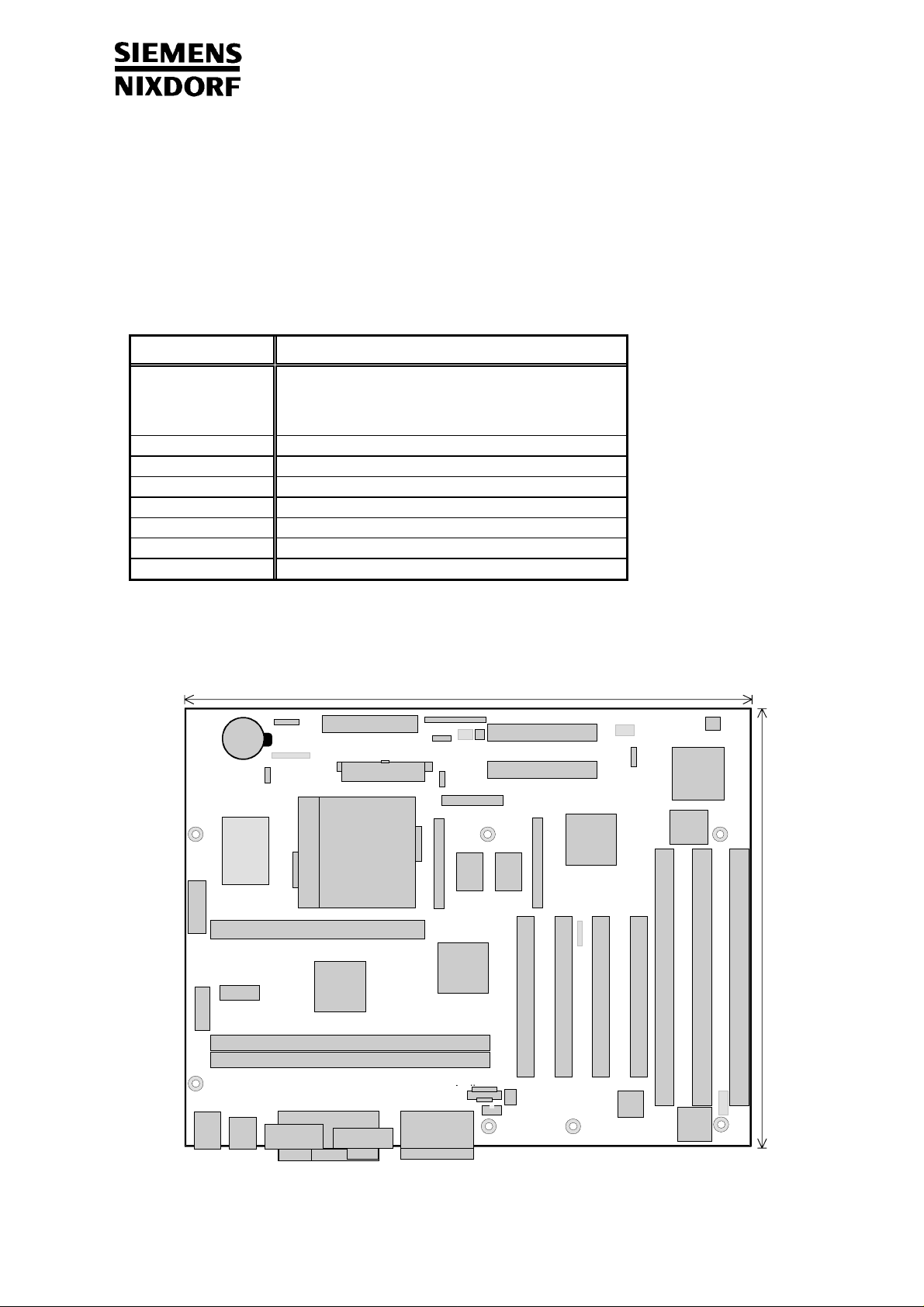
2.1 Layout
ATX 12’’ x 9,2’’ (305mm x 234mm)
Batter
23
VCORE
VoltageRegulator
Serial 2
11
COAST CACHE MODULE
CLOCK
DIP-Switch
22
USB B
USB A
Mouse
Keyboard
Floppy
8
IrDa
20
ATX Power-
7
Supply
SOCKET 7
MTXC
EDO/SDRAM DIMM MODULES Bank 1
EDO/SDRAM DIMM MODULES Bank 0
ParallelSerial 1 VGA
12 ''
4
SCSI-LED
6
21
VGA Memor
Matrox
MGA-1064SG
Audio
Gameport
(305 mm)
Front Panel 1
3
1
Fan
Feature
SGRAM
upgrade VGA Memory upgrade
CD-ROM
17
9
Power ON
9
SGRAM
PCI-SLOT 4
13
MPEG
18
Audio
PCI-IDE 2
PCI-IDE 1
PCI-SLOT 3
Voice Modem
PIIX 4
PCI-SLOT 2
5
Speaker
PCI-SLOT 1
Audio
ISA-SLOT 3
2
Faxcard ON
ULTRA I/O
BIOS
ISA-SLOT 2
ISA-SLOT 1
Wavetable
9,2 ''
(234 mm
1
A26361-D990-Z180-2-7619
Revision 1.0 Seite
/ 11
Keyboar d
13
USB
15
A & B
Additional Technical Manual D990
Gameport
12
Parallel
16
14
Mouse
10
Serial 1
CAUTION:
Computer mainboards and components contain very delicate IC chips. To protect them against damage
caused from electric static, you have to follow some precautions:
Unplug your computer when you work inside
•
Hold components by the edge, don’t touch their leads
•
Use a grounded wrist strap
•
Place the mainboard and the components on a grounded antistatic pad whenever you work outside the
computer
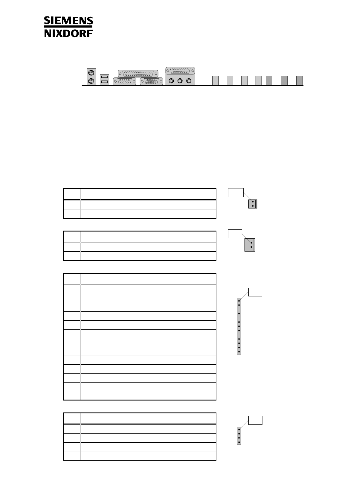
2.1.1 Power ON Switch-Connector
Pin
Signal
GND
1
Power-On Pulse (low asserted)
2
2.1.2 Faxcard-On-Connector
Pin
Signal
GND
1
Remote On
2
VGA
16
Audio
PCI Slots ISA Slots
24
Pin 1
Pin 1
2.1.3 Front Panel Connector 1
Pin
Signal
Boot Lock
1
+ Standby LED
2
3 Key
+ Power LED
4
5 Key
- Standby / Power LED
6
7 n.c.
GND
8
9 Key
+ HD LED
10
HD LED
11
HD LED
12
+ HD LED
13
2.1.4 SCSI-LED Connector
Pin
Signal
1 n.c.
HD-LED
2
HD-LED
3
4 n.c.
Pin 1
Pin 1
A26361-D990-Z180-2-7619
Revision 1.0 Seite
2
/ 11
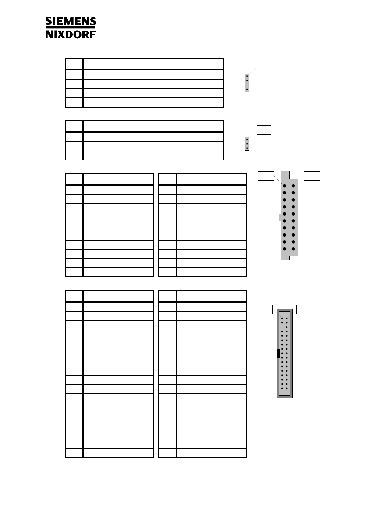
2.1.5 Speaker Connector
Pin
Signal
VCC
1
GND
2
3 Key
SPEAKER OUT
4
2.1.6 FAN Connector (symmetrical)
Pin
Signal
GND
1
+ 12 V
2
GND
3
2.1.7 ATX-Power-Supply-Connector
Pin
Signal
Additional Technical Manual D990
Pin
Signal
Pin 1
Pin 1
Pin 1Pin 11
3.3 V
11
- 12 V
12
GND
13
PS-ON
14
GND
15
GND
16
GND
17
- 5 V
18
5 V
19
5 V
20
2.1.8 Floppy Connector
Pin
Signal
GND
1
3 GND 4 n.c.
5 Key 6 n.c.
GND
7
GND
9
GND
11
GND
13
GND
15
GND
17
GND
19
GND
21
GND
23
GND
25
GND
27
GND
29
GND
31
GND
33
1
2
3
4
5
6
7
8
9
10
Pin
2
8
10
12
14
16
18
20
22
24
26
28
30
32
34
3.3 V
3.3 V
GND
5 V
GND
5 V
GND
Power OK
5 V SB
12 V
Signal
FDHDIN
Index
Motor Enable A
Drive Select B
Drive Select A
Motor Enable B
Step DIR
Step Pulse
Write Data
Write Enable
Track 0
Write Protect
Read Data
Side 1 Select
Disk Change
Pin 2Pin 1
A26361-D990-Z180-2-7619
Revision 1.0 Seite
3
/ 11
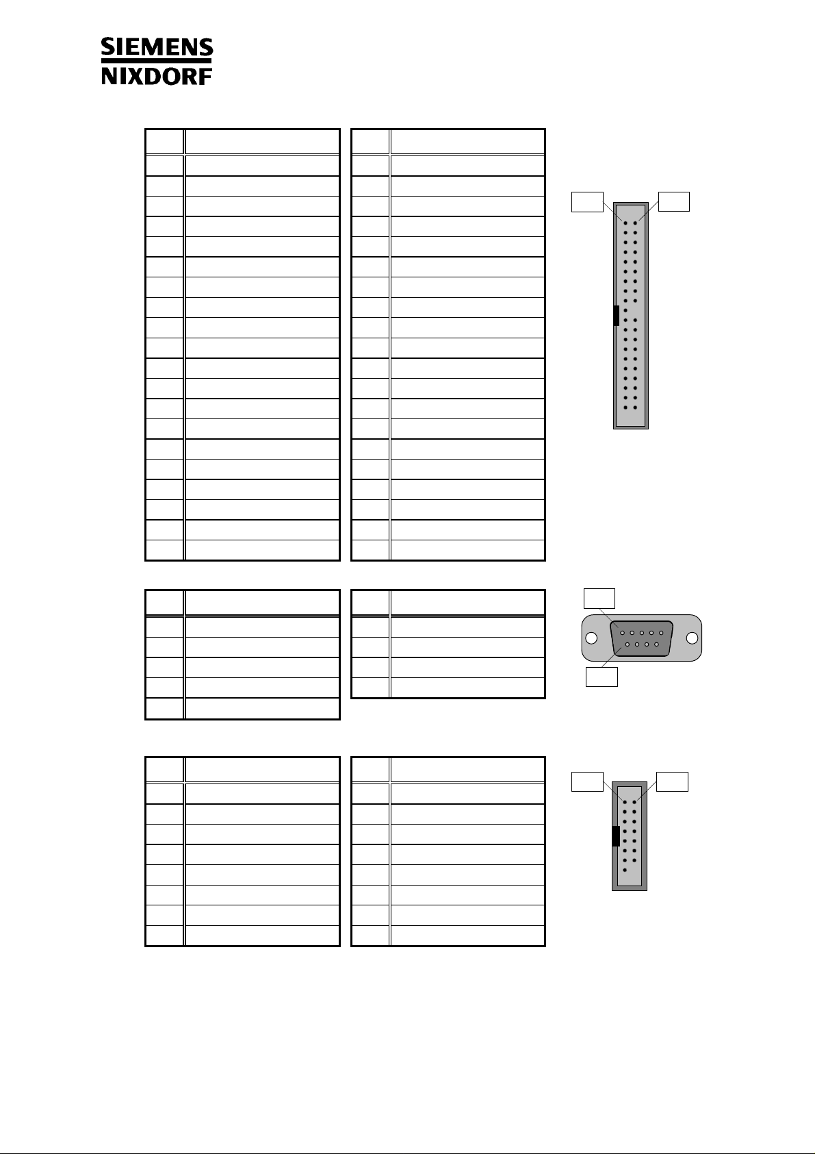
2.1.9 PCI-IDE Connector
Pin
Signal
Additional Technical Manual D990
Pin
Signal
Reset Drive
1
Data 7
3
Data 6
5
Data 5
7
Data 4
9
Data 3
11
Data 2
13
Data 1
15
Data 0
17
19 GND 20 Key
DRQ
21
I/O Write
23
I/O Read
25
IORDY
27
29 DACK 30 GND
31 IRQ 32 n.c.
33 ADR 1 34 n.c.
ADR 0
35
Chip Select 1
37
IDE-LED
39
2
4
6
8
10
12
14
16
18
22
24
26
28
36
38
40
GND
Data 8
Data 9
Data 10
Data 11
Data 12
Data 13
Data 14
Data 15
GND
GND
GND
Cable Select
ADR 2
Chip Select 3
GND
Pin 1
Pin 2
2.1.10 Serial Port 1 (V24)
Pin
Signal
1 DCD 1 6 DSR 1
2 SIN 1 7 RTS 1
3 SOUT 1 8 CTS 1
4 DTR 1 9 RI 1 (Remote On)
5 GND
2.1.11 Internal Serial Port 2 for Cardreader
Pin
Signal
1 DCD 2 2 DSR 2
3 SIN 2 4 RTS 2
5 SOUT 2 6 CTS 2
7 DTR 2 8 PC_ON_Strobe
9 GND 10 VCCHELP
11 EXTSMI 12 VCC
13 RESETDRV 14 GND
15 GND 16 Key
Pin
Pin
Signal
Signal
Pin 1
Pin 6
Pin 1 Pin 2
A26361-D990-Z180-2-7619
Revision 1.0 Seite
4
/ 11
 Loading...