

Page 1
Introduction
This Technical Manual applies for the System board D981.
This system board is available in different configuration levels. Depending
i
on the hardware configuration of your device, it may be that you cannot
find several options in your version of the system board, even though
they are described.
You may find further information in the description "BIOS Setup".
Further information to drivers is provided in the readme files on hard disk or on the
supplied drivers diskettes or on the "Drivers & Utility" CD.
Notational conventions
The meanings of the symbols and fonts used in this manual are as follows:
Pay particular attention to texts marked with this symbol. Failure to
!
observe this warning endangers your life, destroys the system, or may
lead to loss of data.
This symbol is followed by supplementary information, remarks and tips.
i
Texts which follow this symbol describe activities that must be performed in the
²
order shown.
This symbol means that you must enter a blank space at this point.
³
This symbol means that you must press the Enter key.
´
´
Texts in this typeface
Texts in this bold typeface
Texts in italics
"Quotation marks" indicate names of chapters and terms that are being
emphasized.
A26361-D981-Z120-9-7419
indicate commands or menu item.
are screen outputs from the PC.
are the entries you make via the keyboard.
English - 1
Page 2

Introduction Features
Features
System board in ATX format
•
Intel Pentium II processor with MMX technology and 512 Kbyte second-level
•
cache in the processor cache module
Processor cache module with SEC contact technology for Intel Slot 1
•
processor slot (SEC = Single Edge Contact)
16 to 512 Mbytes main memory (SDRAM)
•
Error identification and error recognition via ECC
•
2 or 4 Mbit Flash-BIOS
•
1 AGP slot for AGP graphics controller (AGP = Accelerated Graphics Port)
•
3 PCI slots (all with busmaster capability)
•
2 ISA slots
•
1 ISA/PCI lot (shared)
•
IDE hard disk controller connected to PCI bus for up to four IDE drives
•
(e.g. IDE hard disk drives, ATAPI CD ROM drive)
Real-time clock/calendar with integrated battery backup
•
Floppy disk controller (up to 2.88 Mbytes format)
•
Parallel interface (ECP- and EPP-compatible)
•
2 serial ports (16C550 compatible with FIFO)
•
PS/2 mouse port
•
PS/2 keyboard port
•
Security functions
•
USB (Universal Serial Bus)
•
Energy saving functions
•
Connector for external loudspeaker
•
Connector for chipcard reader
•
2 - English
A26361-D981-Z120-9-7419
Page 3

Features Introduction
A
Optional Components
Audio controller on ISA-BUS (PnP) Crystal CS 4235 Audio Codec or CS 4236
•
Audio Codec, 16 bit stereo; compatible with Soundblaster Pro™, Windows
Sound System and MPU 401; 3D audio support; internal FM synthesis
The audio output can be set in the BIOS Setup in the screen
i
•
•
•
•
•
•
•
•
•
•
•
•
dvanced/Peripheral Configuration
or
Amplifier Level
loudspeaker (with amplifier) to the audio output. Use
use passive loudspeakers
Connector for CD-line in, Game/Midi, Voice-Modem, AUX IN
Microphone connector (via supplementary board)
Audio input (Line in)
Loudspeaker connector (active/passive)
Socket for wavetable chip
SCSI controller Adaptec 7880
SCSI bus (termination)
Fan connector
Connector for remote-on (fax/modem board)
Connector for infrared connection
Wakeup on LAN (WOL)
Prepared for Siemens Nixdorf system monitoring
. Use
Line Level
, menu option
if you connect headphones or an active
.
Audio Output
Amplifier Level
to
Line Level
if you
A26361-D981-Z120-9-7419
English - 3
Page 4
Introduction External ports
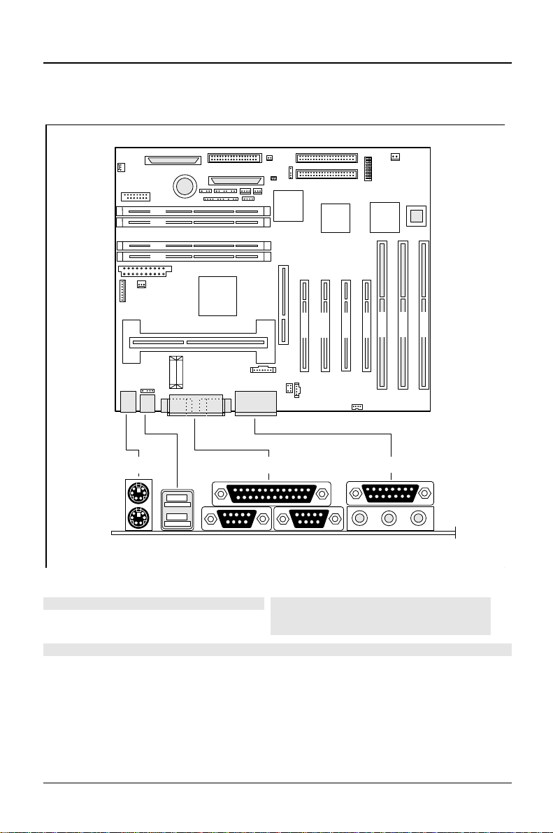
External ports
4 3 2 1
ISA 3
ISA 1
PCI 2
PCI 3
PCI 4
ISA 2
PCI 1
1 2
45
1 = PS/2 mouse port
2 = Parallel port
3 = MIDI/Game port
4 = PS/2 keyboard port
5 = USB ports
6
7
6 = Serial port 1
7 = Serial port 2
8 = Audio port (Line out)
9 = Audio port (Line in)
10 = Audio port (Microphone)
3
89
The connectors marked do not have to be present on the system board.
4 - English
10
A26361-D981-Z120-9-7419
Page 5

Important notes
Store this manual close to the device. If you pass on the device to third parties,
you should also pass on this manual.
Be sure to read this page carefully and note the information before you
!
open the PC.
Please note the information provided in the chapter "Safety" in the
Operating Manual of the PC.
Incorrect replacement of the lithium battery may lead to a risk of
explosion. It is therefore essential to observe the instructions in the
chapter „Add-on modules
The lithium battery must be replaced with an identical battery or a battery
type recommended by the manufacturer (CR2032).
Do not throw lithium batteries into the trashcan. It must be disposed of in
accordance with local regulations concerning special waste.
The shipped version of this board complies with the requirements
of the EEC directive 89/336/EEC with regard to "Electromagnetic
compatibility".
Compliance was tested in a typical PC configuration.
When installing the board, refer to the specific installation
information in the Operating Manual or Technical Manual of the
receiving device.
“ - „Replacing the lithium battery“.
Connecting cable for peripherals must be adequately insulated to avoid
interference.
The heat sink can become very hot during operation. Make sure you do
!
not touch modules when adding components to the system board. There
is a danger of burns!
The warranty expires if the device is damaged during the installation or
i
replacement of system expansions. Information on which system
expansions you can use is available from your sales office or the
customer service.
A26361-D981-Z120-9-7419
English - 5
Page 6

Important notes
Boards with electrostatic sensitive devices (ESD) may be identified by labels.
When you handle boards fitted with ESDs, you must observe the following points
under all circumstances:
You must always discharge yourself (e.g. by touching a grounded object)
•
before working.
The equipment and tools you use must be free of static charges.
•
Pull out the power plug before inserting or pulling out boards containing
•
ESDs.
Always hold boards with ESDs by their edges.
•
Never touch pins or conductors on boards fitted with ESDs.
•
6 - English
A26361-D981-Z120-9-7419
Page 7
Settings
PCI 4
PCI 3
PCI 2
PCI 1
ISA 3
ISA 2
ISA 1
4 3 2 1
ON
1
234
OFF/OPEN
5
678
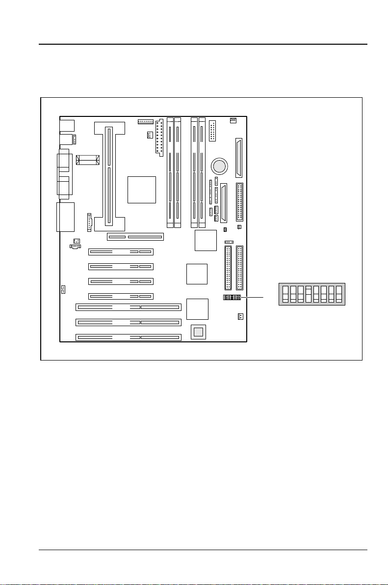
Switch 1 = must be set to
off
Switch 2 = System BIOS recovery
Switch 3 = Write protection for floppy disks
A26361-D981-Z120-9-7419
Switch 4 = reserved
Switch 5 - 8 = clock frequency
English - 7
Page 8
Settings Recovering System BIOS - switch 2
Recovering System BIOS - switch 2
Switch 2 enables recovery of the old system BIOS after an attempt to update has
failed. To restore the old system BIOS you need a Flash BIOS Diskette (call
customer service).
on
off
The System BIOS executes from floppy drive A: and restores the
System BIOS on the system board.
The System BIOS is started from the system board (default setting).
Write protection for floppy disks - switch 3
Switch 3 is used to define whether floppy disks can be written or deleted in the
floppy disk drive. To write and delete floppy disks, the write -protection in
must be disabled (in menu
setup
Enabled
on
off
).
The floppy disk drive is write-protected.
Read, write and delete floppy disks is possible (default setting).
Security
, the field
Diskette Write
must be set to
BIOS
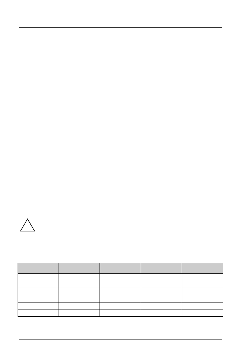
Clock speed - switch 5, 6, 7 and 8
The switches may only be set as specified in the table below for the
!
particular processor used.
This system board you may use only with processors with a host bus
frequency of 66 MHz. Do not use processors with a host bus frequency of
100 MHz!
processor switch 5 switch 6 switch 7 switch 8
233/66 MHz on on off off
266/66 MHz on off on on
300/66 MHz on off on off
333/66 MHz on off off on
366/66 MHz on off off off
Reserved off x x x
8 - English
A26361-D981-Z120-9-7419
Page 9
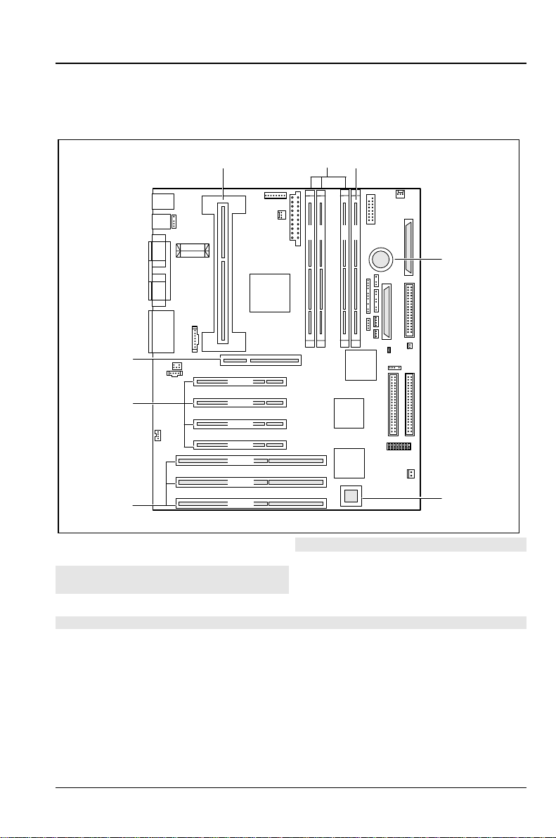
Add-on modules
1
4 3 2 1
3
2
8
PCI 4
7
6
1 = Pentium II with heat sink
2 = 3 locations for main memory (DIMM)
3 = 1 optional locations for main memory
(DIMM)
PCI 3
PCI 2
PCI 1
ISA 3
ISA 2
ISA 1
5 = Socket for wavetable chip (optional)
6 = 3 ISA slots
7 = 4 PCI slots
8 = 1 AGP slot
4 = Lithium battery
The connectors marked do not have to be present on the system board.
4
5
A26361-D981-Z120-9-7419
English - 9
Page 10

Add-on modules Upgrading main memory
Upgrading main memory
The system board incorporates three or four locations for installing memory
modules in DIMM format. The board supports a maximum of 512 Mbytes.SDRAM
memory modules can be used.
You may use memory modules of different size.
DIMM = Dual Inline Memory Module
SDRAM = Synchronous Dynamic Random Access Memory
You may only use unbuffered 3.3V memory modules. Buffered memory
!
modules are not permitted.
SDRAM memory modules must have a cycle time of 15 ns or less or be
designed for a clock frequency of 66 MHz.
Installing memory modules
Flip the holders on each side of the relevant location outwards.
²
Insert the memory module into the location.
²
At the same time flip the lateral holders upwards until the memory module
²
snaps in place.
Removing a memory module
Flip the holders to the right and left of the location outwards.
²
Pull the memory module out of its location.
²
10 - English
A26361-D981-Z120-9-7419
Page 11
Installing/removing the Pentium II Add-on modules
Installing/removing the Pentium II
This system board you may use only with processors with a host bus
!
frequency of 66 MHz. Do not use processors with a host bus frequency of
100 MHz!
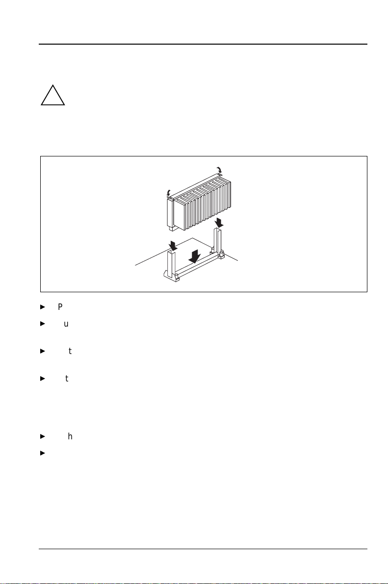
Installing the Pentium II
2
2
1
1
1
²
Place the Pentium II in the holder (1).
²
Push the Pentium II down in the holder and press it into the slot until the
clamps (2) to the left and right snap into place.
²
Set the clock frequency of the new Pentium II using switches 5 to 8 of the
switch block.
²
If the Pentium II has a fan, attach the associated cable to the connector for
the processor fan on the system board.
Removing the Pentium II
²
If the Pentium II has a fan, pull out the associated cable.
²
Press the clamps (2) on either side of the Pentium II inwards and pull the
Pentium II up and out.
A26361-D981-Z120-9-7419
English - 11
Page 12
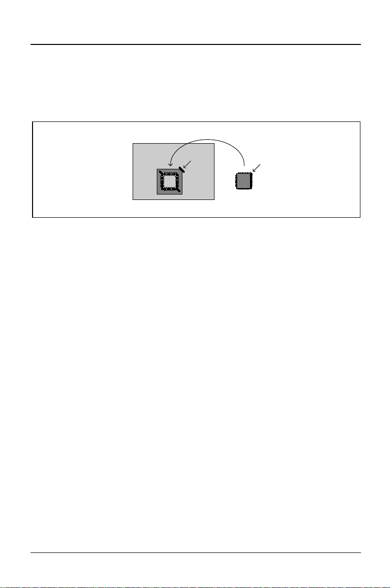
Add-on modules Upgrading the wavetable module
Upgrading the wavetable module
If the system board is prepared for upgrading with a single-chip wavetable module
(Crystal CS9236), the upgrade is carried out as shown in the figure.
12 - English
A26361-D981-Z120-9-7419
Page 13

Replacing the lithium battery Add-on modules
Replacing the lithium battery
Incorrect replacement of the lithium battery may lead to a risk of
!
explosion.
The lithium battery must be replaced with an identical battery or a battery
type recommended by the manufacturer (CR2032).
Do not throw lithium batteries into the trashcan. It must be disposed of in
accordance with local regulations concerning special waste.
Make sure that you insert the battery the right way round. The plus pole
must be on the top!
1
+
+
²
Lift the contact (1) a few millimeters and remove the battery from its
socket (2).
²
Insert a new lithium battery of the same type in the socket (3).
2
+
3
+
A26361-D981-Z120-9-7419
English - 13
Page 14

Connectors and resources Overview of connections
Connectors and resources
Overview of connections
25
24
23
22
21
PCI 4
PCI 3
PCI 2
PCI 1
ISA 3
ISA 2
ISA 1
1 = Processor fan
2 = Power supply monitor
3 = Power supply
4 = Chipcard reader
5 = System fan
6 = SCSI bus (termination)
7 = Loudspeaker
8 = Floppy disk drive
9 = Control panel 1
10 = Control panel 1
11 = SCSI bus (controller)
12 = System Management / I
2
C-Bus
13 = SCSI LED input for SCSI adapter
1
2
3
4 3 2 1
4
14 = Wake-up on LAN
15 = ON/OFF switch
16 = Intrusion plug
17 = Infrared receiver (IrDA)
18 = IDE drives 1 and 2 (primary)
19 = IDE drives 3 and 4 (secondary)
20 = Remote on via fax/modem
21 = AUX-Line in (AUX input)
22 = CD-Line in (Audio input)
23 = Voice modem
24 = Device ID and temperature
25 = USB connection (internal)
5
6
7
8
9
10
11
12
13
14
15
16
17
18
19
20
The marked connectors are optional and may therefore not be included on your system
board.
14 - English
A26361-D981-Z120-9-7419
Page 15

Resource table Connectors and resources
Resource table
assigned
IRQ
Keyboard IRQ1
IrDA / WOL /
Serial port COM2
Serial interface COM1 /
Chip card reader
Floppy disk drive controller IRQ6 DMA2
Parallel interface LPT1 IRQ7 IRQ5, IRQ7 0278, 0378 DMA1,
RTC IRQ8
Audio controller
Joystick:
Base address:
MPU 401:
Adlib:
USB controller IRQ11
Mouse controller IRQ12
Numeric processor IRQ13
IDE controller 1 IRQ14
IDE controller 2 IRQ15
„Assigned IRQ“ = Interrupts assigned as shipped
„Possible IRQ/Address/DMA“ = can be used for your particular application
MPU 401: If you want to use external MIDI devices (for example a MIDI
i
keyboard), you must assign an interrupt for the MPU 401 (MIDI interface).
Detailed information is provided in the audio documentation on the driver
and utility CD.
Please note that a resource cannot be used by two applications at the
same time.
IRQ3 02F8, 03F8
IRQ4 03F8, 02F8
possible IRQ Possible
Address
02E8, 03E8
03E8, 02E8
IRQ5, IRQ7,
IRQ9,
IRQ10 0200-0207
0220-022F
0240-024F
0260-026F
0280-028F
0300-0301
0330-0331
0338-038B
Possible
DMA
DMA3
DMA1,
DMA3,
DMA5,
DMA7
A26361-D981-Z120-9-7419
English - 15
Page 16

Page 17

SCSI Setup
SCSI is the abbreviation for Small Computer System Interface.
The onboard ultra-wide SCSI controller (host adapter) is the interface between the
internal bus (PCI bus) and devices with SCSI interfaces (SCSI devices).
The onboard ultra-wide SCSI controller is a PCI chip which uses Bus Master
technology. This allows your SCSI controller to independently manage data
transfer between your SCSI peripherals and the computer system memory, without
requiring the involvement of your computer system CPU (Central Processing Unit).
All the information you require to install the SCSI Utility Software (e. g. drivers for
MS-DOS, Windows 3.x) is contained in the User Guide for the SCSI Utility
Software EZ-SCSI.
Details of how you install and operate your SCSI device may be found in the
associated Manual.
Setting SCSI addresses (IDs)
Each device which is connected to the ultra-wide SCSI controller must be set to a
separate SCSI address (ID 0 through ID 15).
The ultra-wide SCSI controller has ID 7. ID 7 has the highest priority, SCSI-ID 0
has the lowest. The priority of the remaining IDs, in descending order, is 15 to 8.
Ensure that each SCSI device is assigned it's own address.
²
Details how you set the SCSI address of your SCSI devices may be found in the
associated manual.
A26361-D981-Z120-9-7419
English - 17
Page 18

Connecting SCSI devices SCSI Setup
Connecting SCSI devices
SCSI devices and controllers are connected together via a common cable (SCSI
bus).
The termination (terminating resistors) must be enabled (or installed) on the last
device connected to the SCSI cable. The termination must be disabled (or
removed) from all other SCSI devices.
How you activate or deactivate the termination of the SCSI devices, see
description of your SCSI devices.
The system board provides the
Instead of terminating the last drive on the SCSI line, you can also plug the free
end of the SCSI line into the
1
1 = SCSI bus port (controller)
2 = SCSI line
3 = SCSI bus port (termination)
Be sure the ends of the SCSI bus are correctly terminated.
²
Connect the SCSI devices to the
²
means of the SCSI cable.
Only single-ended SCSI devices may be linked to the ultra-wide SCSI
i
controller. Most SCSI devices meet this requirement. If you are in any
doubt, contact your sales office or customer service.
How you install internal devices in the system unit and connect them to the power
supply is described in the Operating Manual or Technical Manual for your device
in the chapter "System unit" (paragraph "Installing a disk drive").
SCSI bus termination
SCSI bus termination
4
5
2
4 = SCSI drive 1 (not terminated)
5 = SCSI drive 2 (not terminated)
6 = SCSI drive 3 (not terminated)
SCSI connector on the system board by
port to terminate the SCSI bus.
port.
6
3
Further information is provided in the descriptions of your SCSI devices.
18 - English
A26361-D981-Z120-9-7419
Page 19

SCSI Setup SCSI Setup
The following hints are only for the connectors at the onboard ultra-wide SCSI
controller.
Connectors and cables
The connector of the ultra-wide SCSI controller is 68pin.
The connector of 8-bit SCSI devices is 50pin; the connector of 16-bit SCSI devices
is 68pin.
If you want to connect 8-bit SCSI devices to the ultra-wide SCSI controller you
need an adapter (from 68pin to 50pin).
If you want to operate an 8-bit SCSI device as the last device on a SCSI line you
need an adapter (from 68pin to 50pin) with high-byte termination.
If you have set the
connect 7 SCSI devices with a maximum cable length of 1.50 m.
Only use good quality SCSI lines, otherwise you may have transmission
i
problems.
Support for Ultra SCSI Speed
menu item to
Enabled
, you may only
SCSI Setup
The BIOS of the ultra-wide SCSI controller includes a menu-driven
program allows you to change almost all of the option settings of the SCSI
controller and the connected SCSI devices.
When you boot the system a SCSI-BIOS message listing the SCSI devices
connected is displayed.
If an SCSI-BIOS error message appears or problems arise with SCSI
i
devices, please refer to the chapter entitled "Eliminating errors on the
SCSI controller" and "SCSI BIOS messages".
You may find further information in the documentation of your SCSI
device.
If you are unable to trace or rectify the error, please contact your dealer
or our service.
SCSI Setup
. This
A26361-D981-Z120-9-7419
English - 19
Page 20

SCSI Setup SCSI Setup
Starting the SCSI Setup
You must enable the ultra-wide SCSI controller in the system BIOS to be able to
call the
Peripheral Configuration
²
Press <Ctrl> <A> for SCSI Select (TM) Utility!
The first menu of the
Utilities
Working with the keyboard
Use the following keys when running the program:
SCSI Setup
Start your PC and press key combination
message appears:
is displayed.
. Call the
BIOS Setup
menu to
SCSI setup, Configure/View Host Adapter Settings
enabled
and set the
.
>&WUO@
>&WUO@
SCSI Controller
and
>$@
>$@
field in the
, when the following
and
SCSI Disk
¤
¥
¤
¥
Ï
Ï
^(VF`
^(VF`
^)`
^)`
^)`
^)`
Also note the status line at the bottom of the screen.
to make selections
to accept a selection
to call the previous menu and to terminate the
to reset to the default settings
to toggle display between color and monochrome mode
SCSI setup
.
Terminating the SCSI setup
Depending on the current menu level, you can display the previous menu by
pressing the
prompted to store them.
Keep pressing
²
Adapter Settings
Press the
²
screen to terminate the
key. If you have made changes in the current menu you will be
>(6&@
>(6&@
until you arrive at the first menu (
>(6&@
>(6&@
).
key in the first menu and then follow the instructions on the
>(6&@
>(6&@
SCSI Setup
.
Configure/View Host
20 - English
A26361-D981-Z120-9-7419
Page 21

SCSI Setup Default Settings in the SCSI setup
Default Settings in the SCSI setup
SCSI Bus Interface Definitions Default setting
Host Adapter SCSI ID 7
SCSI Parity Checking Enabled
Host Adapter SCSI Termination LowON/HighON
Additional Options Default setting
Boot Device Options
Boot Target ID 0
Boot LUN Number* 0
SCSI device configuration ( for each SCSI device)
SCSI device ID 1 to 15
Initiate Sync Negotiation Yes
Maximum Sync Transfer Rate 40 Mbyte/s
Enable disconnection Yes
Initiate wide negotiation Yes
Send Start Unit Command** Yes
Include in BIOS Scan Yes
Advanced Configuration Options Default setting
Reset SCSI Bus at IC Initialization Enabled
Host Adapter BIOS Enabled
Support Removable Disks Under BIOS as
Fixed Disks**
Extended BIOS Translation for DOS Drives
>1 Gbyte**
Display
>&WUO@
>&WUO@
-
Message During BIOS
>$@
>$@
Initialization**
Multiple LUN Support** Disabled
BIOS Support for Bootable CD-ROM** Enabled
BIOS Support for Int 13 Extensions** Enabled
Support for Ultra SCSI Speed Enabled
* The setting is valid only if
Multiple LUN Support
is
enabled
Boot only
Enabled
Enabled
.
** The setting is valid only if SCSI controller BIOS is
A26361-D981-Z120-9-7419
Enabled
.
English - 21
Page 22

SCSI Bus Interface Definitions SCSI Setup
SCSI Bus Interface Definitions
Host Adapter SCSI ID
All SCSI devices on one SCSI bus, including the Ultra-Wide SCSI controller, must
be set to separate SCSI IDs.
0, 1, 2, 3, 4, 5, 6, 7, 8, 9, 10, 11, 12, 13, 14, 15
The ultra-wide SCSI controller is set to the displayed SCSI address
(default entry: 7).
SCSI Parity Checking
The ultra-wide SCSI controller uses parity bits on the SCSI bus to verify the data
from your SCSI devices. Parity checking may not be supported on older SCSI
devices. You must disable the option in this case.
Enabled
Disabled
i
Host Adapter SCSI Termination
If the ultra-wide SCSI controller is the last device on the SCSI cable, its
termination must be enabled. If the ultra-wide SCSI controller is not the last device
on the SCSI cable, its terminator must be disabled.
LowON/HighON
LowOFF/HighOFF
LowON/HighON
Parity checking is enabled (default setting).
Parity checking is disabled.
If parity checking is disabled, this applies to all SCSI devices on the SCSI
bus.
The termination is enabled (default entry).
The termination is disabled.
Not supported.
22 - English
A26361-D981-Z120-9-7419
Page 23

SCSI Setup Additional Options
Additional Options
Boot Device Options
Boot Target ID
The ultra-wide SCSI controller can start the operating system from a drive with any
SCSI address (ID). The SCSI ID selected here must correspond to the ID
configured on the boot device.
0, 1, 2, 3, 4, 5, 6, 7, 8, 9, 10, 11, 12, 13, 14, 15
The ultra-wide SCSI controller boots from the drive with the
displayed SCSI ID (default entry: 0).
Boot LUN Number
If your boot device has multiple LUNs (Logical Unit Numbers) and
is
Support
your boot device.
0, 1, 2, 3, 4, 5, 6, 7
Enabled
, this option allows you to specify which LUN to boot from on
The ultra-wide SCSI controller boots with the displayed LUN (default
entry: 0).
Multiple LUN
SCSI Device Configuration
Initiate Sync Negotiation
Devices on the SCSI bus (including the SCSI controller) communicate intelligently
with each other. Before data is transferred across the bus, the sending (initiating)
and receiving (target) devices negotiate and agree on how long each piece of data
will be, and how many pieces will be sent at a time - that is, they agree on how fast
to talk.
If you have operating problems with older SCSI devices, you should disable
Sync Negotiation
SCSI device description).
A26361-D981-Z120-9-7419
. You may have to make settings on your SCSI devices (see the
Initiate
English - 23
Page 24

Additional Options SCSI Setup
When
Sync Negotiation
go into synchronous mode if it receives a request from one of your SCSI devices.
It can, however, also exchange data with slow SCSI devices.
Yes
No
The function is enabled (default entry).
The function is disabled.
Synchronous data transfer is required for fast and ultra SCSI operation.
is disabled, the Ultra-Wide SCSI controller will automatically
i
Initiate wide negotiation
This option determines whether the SCSI controller attempts 16-bit data transfer
(Wide SCSI) instead of 8-bit data transfer.
Only disable
8 bit SCSI devices have problems during operation. You may have to make
settings on your SCSI devices. (refer to the documentation supplied with your
SCSI device).
Fast SCSI devices, including the ultra-wide SCSI controller, are capable of
transferring data to and from the SCSI bus at speeds ranging up to 40 Mbyte/s.
Yes
No
Initiate Wide Negotiation
The function is enabled (default entry).
The function is disabled.
if you do not use any wide SCSI devices or if
Maximum Sync Transfer Rate
Fast SCSI devices (ultra-wide), including the ultra-wide SCSI controller, are
capable of transferring data to and from the SCSI bus at speeds ranging up to
40 Mbyte/s at synchronous data transfer. If you have entered
Support for Ultra SCSI Speed
automatically.
24 - English
menu item, the transfer rate of 40 Mbyte/s is entered
in the
Enabled
A26361-D981-Z120-9-7419
Page 25

SCSI Setup Additional Options
Enable disconnection
SCSI devices can release the SCSI bus during command execution with this
function. A typical example of this is a tape device that has no need to access the
SCSI bus during rewinding and can be "disconnected" from the SCSI bus for this
period.
You can disable the function if you have only connected one SCSI device. In this
case, disconnection improves performance.
Yes
No
Send Start Unit Command
If the function is enabled, SCSI devices which support it are only started when
they receive the "Start-Unit" command from the SCSI BIOS. This allows the SCSI
devices to be activated consecutively. This is used if your system power supply is
too weak to start several drives simultaneously or for preventing switchon current
peaks.
You may have to make settings on your SCSI devices to enable support for this
function (see the documentation for the SCSI devices).
Yes
No
Include BIOS Scan
The SCSI device can be used as the boot drive if this function is enabled. The
SCSI device is accessed by the SCSI BIOS and is assigned a drive identifier. A
message is displayed on the screen.
Yes
No
The function is enabled (default entry).
The function is disabled.
The function is enabled.
The function is disabled (default entry).
The SCSI device can be the boot drive and is assigned a drive
identifier (default entry).
The SCSI device is not accessed by the SCSI BIOS.
This function should be set to No for drives which you know will never be
i
used as the boot drive (e.g. DAT drives). This saves time during system
startup.
A26361-D981-Z120-9-7419
English - 25
Page 26

Additional Options SCSI Setup
Advanced Configuration Options
RESET SCSI Bus at IC
The SCSI bus is reset if you activate this menu item.
Enabled
Disabled
Host Adapter BIOS
!
The SCSI BIOS can be disabled if the SCSI devices can only be operated with
additionally loaded drivers. This saves 16 Kbytes of system memory as well as
time during system startup.
If you disable the SCSI BIOS, you can still call the
keys during system startup and modify settings.
Enabled
Disabled
i
The SCSI bus will be reset (default entry).
The SCSI bus will not be reset.
If the SCSI BIOS is disabled, the system cannot be booted from any of
the SCSI devices connected to the SCSI bus.
SCSI Setup
The SCSI-BIOS is enabled (default setting).
The SCSI BIOS is disabled.
Note that you will have to install additional drivers for your devices if the
SCSI BIOS is disabled.
with the
>&WUO@
>&WUO@
+
>$@
>$@
26 - English
A26361-D981-Z120-9-7419
Page 27

SCSI Setup Additional Options
Support Removable Disks under BIOS as Fixed Disks
This option allows you to use removable-media drives, such as MO drives, without
installing additional drivers.
Boot Only
All Disks
Disabled
!
Extended BIOS Translation for DOS Drives > 1Gbyte
Enabling this option allows drives of up to 8 Gbyte capacity (2 Gbyte/partition) to
be supported under MS-DOS 5.0 or higher. The SCSI BIOS must be enabled.
In earlier days, it was only possible to use drives with a capacity of up to 1 Gbyte
under MS-DOS 5.0.
Enabled
Disabled
i
Only the removable-media drive designated as the boot device is
treated as a hard disk (default setting).
All removable-media drives supported by the BIOS are treated as
hard disk drives.
No removable-media drives are treated as hard disk drives. In this
situation, software drivers are needed because the drives are not
controlled by the BIOS.
If a removable-media device is controlled by the SCSI controller BIOS, do
not remove the media while the system is switched on.
Drives up to 8 Gbytes can be used under MS-DOS 5.0 (default
entry).
Drives up to 1 Gbyte can be used under MS-DOS 5.0.
Back up the data on your large capacity drive before enabling the option.
After enabling this option, the drive must be re-partitioned and high-level
formatted with the DOS
FDISK
and
FORMAT
programs.
A26361-D981-Z120-9-7419
English - 27
Page 28

Additional Options SCSI Setup
Display
>&WUO@
>&WUO@
>$@
+
Message During BIOS Initialization
>$@
This option determines whether the
Press <Ctrl> <A> for SCSISelect (TM) Utility!
message appears on your screen during system startup.
If this setting is disabled, you can still invoke the
SCSI Setup
by pressing
>&WUO@
>&WUO@
at system startup.
Enabled
Disabled
The message is displayed during startup (default entry).
The message is not displayed during startup.
Multiple LUN Support
This option determines whether booting from a SCSI device that has multiple
LUNs (Logical Unit Numbers) is supported.
Enabled
Disabled
The SCSI device will be used as the startup drive.
The SCSI device will not be used as the startup drive (default entry).
BIOS Support for Bootable CD-ROM
This option determines for booting from a CD-ROM drive. The CD-ROM must
emulate a floppy disk or hard disk drive.
Enabled
Disabled
It is possible to boot from the CD-ROM (default entry).
It is not possible to boot from the CD-ROM.
+
>$@
>$@
BIOS Support for Int 13 Extensions
This option determines whether the SCSI BIOS supports disks with more than
1024 cylinders. The default setting is
Enabled
Hard disk drives with more than 1024 cylinders are supported
Enabled
.
(default entry).
Disabled
28 - English
Hard disk drives with more than 1024 cylinders are not supported.
A26361-D981-Z120-9-7419
Page 29

SCSI Setup SCSI Disk Utilities
Support for Ultra SCSI Speed
This option determines whether the SCSI controller BIOS supports the fast transfer
rate 40 Mbyte/s at 16-bit data transfer.
Enabled
Disabled
i
40 Mbyte/s transfer rate is supported (default entry).
The function is disabled.
Change the default setting if you have connected ultra-wide SCSI devices
to the SCSI controller.
SCSI Disk Utilities
When you select the
devices connected to the SCSI bus. You are also offered two menus for hard disk
drives:
Verify
and
SCSI Disk Utilities
Format Disk
.
Verify
With
detected will be entered in the existing error list for the hard disk.
you can have a selected hard disk drive checked. All defects that are
Verify
Format Disk
With
Format Disk
hard disks are already formatted in low-level format. You should use this menu
item only if you want to erase the hard disk completely and regenerate the error
list.
a selected hard disk is formatted in low-level format. Normally
menu item, you are shown a list of all the
A26361-D981-Z120-9-7419
English - 29
Page 30

Eliminating errors on the SCSI controller SCSI Setup
Eliminating errors on the SCSI controller
Most problems with the onboard ultra-wide SCSI controller occur when SCSI
devices are prepared (e.g. termination) and connected to the SCSI bus. Check the
following points if you have problems with the ultra-wide SCSI controller or the
connected SCSI devices:
Are all SCSI devices supplied with power?
•
Are the SCSI and power cables connected correctly on the SCSI device?
•
Is the SCSI cable connected correctly to the system board?
•
Has each SCSI device and the onboard SCSI controller been set to a different
•
SCSI ID?
Are the SCSI devices and the onboard SCSI controller correctly terminated?
•
Is the SCSI controller activated in the system BIOS (
•
Is parity checking either enabled or disabled on all SCSI devices on the SCSI
•
bus?
BIOS Setup
)?
SCSI BIOS messages
The following messages can appear during system startup if you have enabled the
SCSI BIOS:
Device connected, but not ready
The SCSI device connected to the ultra-wide SCSI controller is not ready (for
example because the drive motor for hard disks does not rotate). Set
to
Start Unit Command
the message still appears, check the settings required for the SCSI device in
its documentation.
Start unit request failed
The SCSI BIOS could not issue a start unit command to the SCSI device. Call
the
SCSI Setup
Time-out failure during ...
A timeout has occurred. Check the SCSI bus termination. Remove the SCSI
cable from the ultra-wide SCSI controller and restart the system. If system
startup is successful, check the SCSI cable. One of the SCSI devices may be
defective. Check the SCSI devices.
30 - English
and set
in the
Yes
Send Start Unit
SCSI Setup
for the SCSI device concerned. If
to No for the SCSI device concerned.
A26361-D981-Z120-9-7419
Send
Page 31

Index
2
!
2
i
²
³
´
´
A
Accumulator 5, 13
Add-on modules 9
Address 15
Advanced
AGP slot 9
Assignment
Audio input, connector 14
Audio, external Ports 4
AUX input, connector 14
AUX Line in, connector 14
B
Battery
BIOS
BIOS Support
BIOS Update 8
BIOS-Setup
2
2
2
Configuration Options 26
address 15
DMA channels 15
interrupt 15
disposal 5, 13
replace 5, 13
System BIOS 8
Ultra-Wide-SCSI controller 19
Bootable CD-ROM 28
Int 13 Extensions 28
Ultra SCSI Speed 29
floppy disk 8
A26361-D981-Z120-9-7419
English - 31
Page 32

Index
Board, safety 6
Boot Device Settings 23
Boot drive 25
Boot LUN Number 23
Boot Target ID 23
C
CD Line in, connector 14
CD-ROM drives 27
CE certificate 5
Chipcard reader, connector 14
Clock speed 8
Command, Start-Unit 25
Connector 14
Control panel, connector 14
D
Data transfer 23, 24
Data transfer rate 24
Default settings, SCSI Setup 21
Device ID, connector 14
DIMM 9, 10
Diskette, write-protection 8
Display Message 28
DMA 15
Drive, capacity 27
E
EDO-DRAM 10
Enable Disconnection 25
ESD 6
Extended BIOS Translation 27
External port 4
F
Fan, connector 14
Features 2
Flash BIOS
floppy disk 8
Floppy disk drive, connector 14
Formatting, hard disk 29
32 - English
A26361-D981-Z120-9-7419
Page 33

H
Hard disk drive
checking 29
formatting 29
Heat sink 9
Host Adapter 17
Host Adapter BIOS 26
Host Adapter SCSI ID 22
Host Adapter SCSI Termination 22
I
I2C bus, connector 14
IDE drive, connector 14
Important notes 5
Infrared receiver, connector 14
Initiate Sync Negotiation 23
Initiate Wide Negotiation 24
Internal connectors 14
Interrupt 15
Intrusion plug, connector 14
ISA slot 9
K
Keyboard port 4
Keys, SCSI Setup 20
Index
L
Line-in, ext. audio port 4
Line-out, ext. audio port 4
Lithium battery 5, 9, 13
Logical Unit Number, see LUN
Loudspeaker, connector 14
Low-Level Format 29
LUN 23, 28
M
Main memory 9
upgrading 10
Maximum Sync Transfer Rate 24
Memory module 10
Memory, main memory 10
Menu
SCSI-Bus Interface Definitions 22
A26361-D981-Z120-9-7419
English - 33
Page 34

Index
Message
Press <Ctrl> <A> for SCSISelect (TM) Utility! 28
Messages, SCSI BIOS 30
Microphone, ext. audio port 4
MIDI/Game port 4
Mouse port 4
Multiple LUN Support 23, 28
N
Name of drive 25
Notational conventions 1
Note
safety 5
O
ON/OFF switch, connector 14
P
Parallel interface 4
Parity monitor 22
PCI slot 9
Pentium II 9
Pentium II installing/removing 11
Ports
external 4
internal 14
Power On switch, connector 14
Power supply, connector 14
Problems, SCSI controller 30
Processor 9
clock frequency 8
Processor fan, connector 14
PS monitoring, connector 14
PS/2 keyboard port 4
PS/2 mouse port 4
R
Real-time clock module 5
Recycling, battery 5, 13
Remote on via fax/modem, connector 14
Remote on via LAN, connector 14
Removable disks 27
Resource table 15
34 - English
A26361-D981-Z120-9-7419
Page 35

S
Safety, board 6
SCSI address 17, 22
SCSI BIOS messages 30
SCSI boot drive 25
SCSI bus 18, 25
connector 14
Interface Definitions 22
reset 26
SCSI cable 18, 19
SCSI controller
activating BIOS 26
problems 30
SCSI device 17
16 bit 19
8 bit 19
connecting 18
does not react 30
SCSI Device Configuration 23
SCSI Disk Utilities 29
SCSI ID 17, 22
SCSI LED
connector 14
SCSI Parity Checking 22
SCSI port 18
50pin 19
68pin 19
SCSI setup 17, 19
calling 20, 26
deactivating 26
default settings 21
exiting 20
operating 20
saving changes 20
SCSI Utility Software 17
SCSI-Bus
termination connector 14
SCSI-ID
priority 17
SDRAM 10
Send Start Unit Command 25
Serial port 1/2 4
Settings
Index
A26361-D981-Z120-9-7419
English - 35
Page 36

Index
SCSI setup 17
switch block 7
Socket for wavetable chip 9
Start-Unit 25
Support
Removable Disks 27
Ultra SCSI Speed 29
Switch
clock frequency 8, 11
System BIOS recovering 8
write protection for floppy 8
Switch block, Location 7
Synchronous data transfer 23
System
memory 10
System BIOS
recovering 8
System board 4
System fan, connector 14
System Management, connector 14
T
Temperature sensor, connector 14
Terminating resistor 18
Termination 18
activated 18
activating 22
deactivated 18
deactivating 22
Transfer rate 24, 29
U
Ultra SCSI Speed 29
Ultra-Wide-SCSI controller 17
connectors/cables 19
Update, system BIOS 8
Upgrading
main memory 10
USB
External port 4
internal connector 14
36 - English
A26361-D981-Z120-9-7419
Page 37

V
Voice modem, connector 14
W
Wavetable chip 9, 12
Wide negotiation, see Data transfer
Write protection, floppy 8
Index
A26361-D981-Z120-9-7419
English - 37
Page 38

Contents
Introduction............................................................................................................1
Notational conventions............................................................................................1
Features.................................................................................................................. 2
External ports ..........................................................................................................4
Important notes .....................................................................................................5
Settings ..................................................................................................................7
Recovering System BIOS - switch 2........................................................................ 8
Write protection for floppy disks - switch 3.............................................................. 8
Clock speed - switch 5, 6, 7 and 8 .......................................................................... 8
Add-on modules.................................................................................................... 9
Upgrading main memory....................................................................................... 10
Installing/removing the Pentium II .........................................................................11
Upgrading the wavetable module..........................................................................12
Replacing the lithium battery................................................................................. 13
Connectors and resources................................................................................. 14
Overview of connections....................................................................................... 14
Resource table...................................................................................................... 15
SCSI Setup........................................................................................................... 17
Setting SCSI addresses (IDs)................................................................................ 17
Connecting SCSI devices...................................................................................... 18
SCSI Setup............................................................................................................ 19
Starting the SCSI Setup................................................................................. 20
Terminating the SCSI setup........................................................................... 20
Default Settings in the SCSI setup........................................................................ 21
SCSI Bus Interface Definitions.............................................................................. 22
Additional Options .................................................................................................23
Boot Device Options....................................................................................... 23
SCSI Device Configuration............................................................................. 23
Advanced Configuration Options.................................................................... 26
SCSI Disk Utilities ................................................................................................. 29
Verify.............................................................................................................. 29
Format Disk....................................................................................................29
Eliminating errors on the SCSI controller .............................................................. 30
SCSI BIOS messages........................................................................................... 30
Index..................................................................................................................... 31
A26361-D981-Z120-9-7419
Page 39

A26361-D981-Z120-9-7419
System board D981
Technical Manual
May 1998 edition
Adaptec and SCSISelect are registered trademarks of Adaptec, Inc.
Creative is a registered trademark, Sound Blaster 16 and VIBRA 16C are trademarks of
Creative Technology Ltd.
Intel and Pentium are registered trademarks and MMX is a trademark of Intel Corporation,
USA.
Microsoft, MS, MS-DOS and Windows are registered trademarks of Microsoft Corporation.
PS/2 is a registered trademark of International Business Machines, Inc.
All other trademarks referenced are trademarks or registered trademarks of their respective
owners, whose protected rights are acknowledged.
Copyright Siemens Nixdorf Informationssysteme AG 1998
All rights, including rights of translation, reproduction by printing, copying or similar methods,
even of parts are reserved.
Offenders will be liable for damages.
All rights, including rights created by patent grant or registration of a utility model or design,
are reserved.
Delivery subject to availability. Right of technical modification reserved.
 Loading...