

Page 1

System board D969
Technical Manual
Page 2

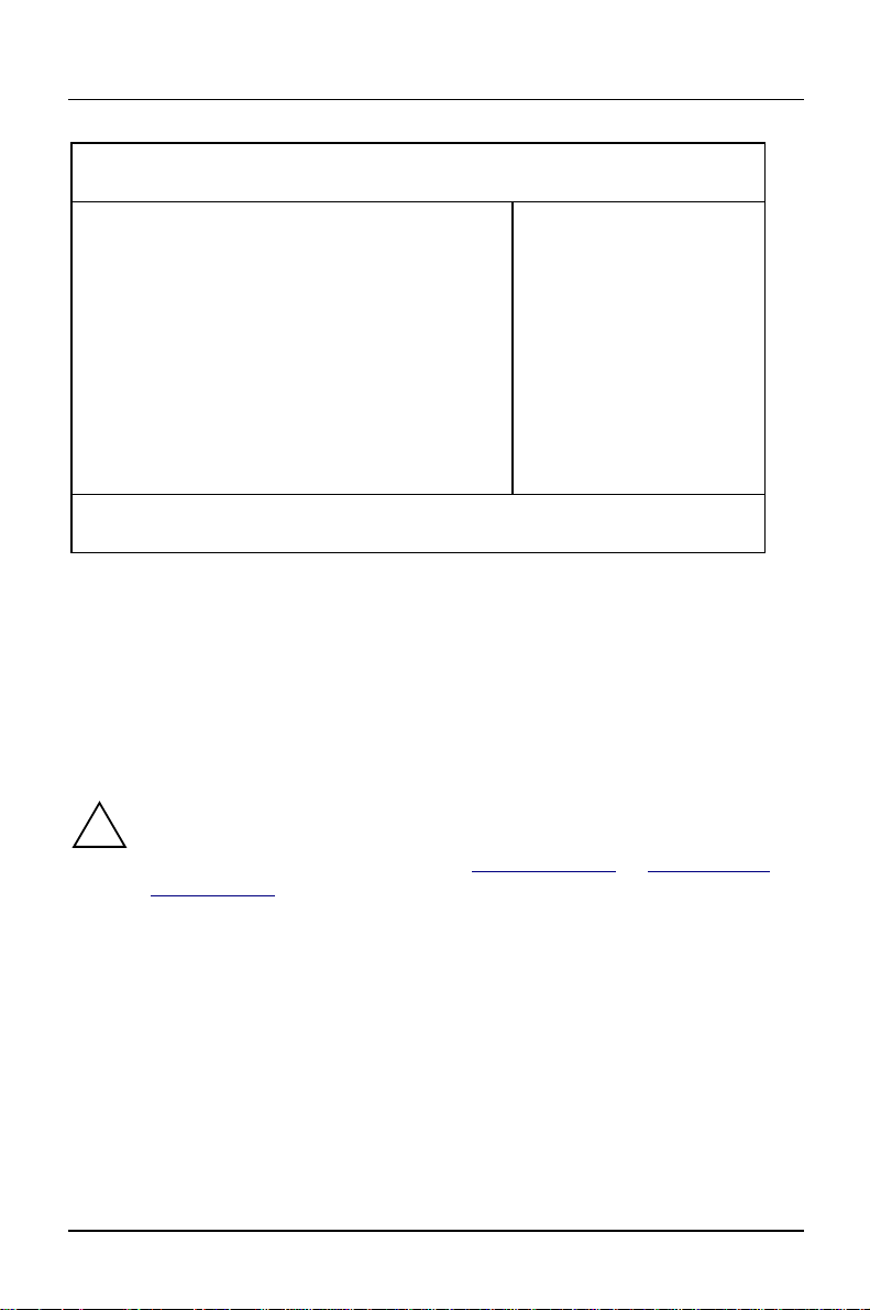
Is there ...
... any technical problem or other
question you need clarified?
Please contact:
• one of our IT Service Shops
• your sales partner
• your sales office
The addresses of your service partners
are contained in the guarantee booklet
or in the service address booklet.
The latest information on our products,
tips, updates, etc., can be found on the
Internet under:
http://www.siemens.com/pc
... anything you want to tell us
about this manual?
Please send us your comments quoting
the order number of the manual.
Siemens AG
User Documentation Department,
ICP CS BS2 OS ID4
Otto-Hahn-Ring 6
D-81730 München
Page 3

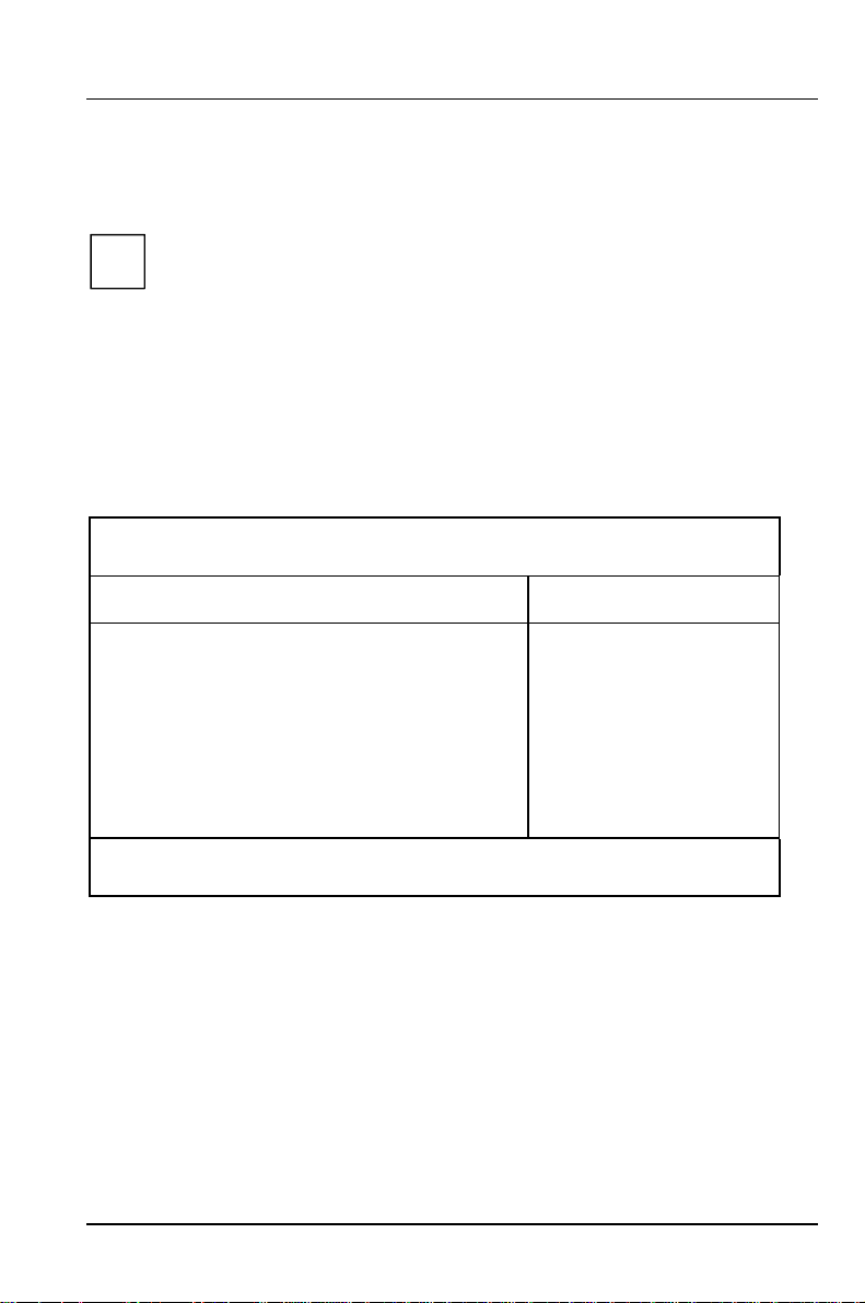
Your training needs?
The Siemens Training Centers offer you a wide range oftraining courses in
information technology and on IT products and other subjects - onsite near to your
workplace or offsite at one of our training centers.
Let us know your training requirements or request information from us the fastest way is via fax under: +49 89 636-42945
Or write to:
Siemens AG
Training Center, Beratungsservice
D-81730 München
Page 4

c
Dieses Handbuch wurde auf Recycling-Papier gedruckt.
This manual has been printed on recycled paper.
Ce manuel est imprimé sur du papier recyclé.
Este manual ha sido impreso sobre papel reciclado.
Questo manuale è stato stampato su carta da riciclaggio.
Denna handbok är tryckt på recyclingpapper.
Dit handboek werd op recycling-papier gedrukt.
Herausgegeben von/Published by
Siemens AG
D-81730 München
System board D969 Techni
Bestell-Nr./Order No.: A26361-D969-Z120-8-7619
Printed in the Federal Republic of Germany
AG 1198 11/98
A26361-D969-Z120-8-7619
A26361-D969-Z120-8-7619A26361-D969-Z120-8-7619
A26361-D969-Z120-1-7619
Page 5

Introduction
k
Important notes
System board D969
Technical Manual
Settings in BIOS Setup
Settings with switch bloc
Add-on modules
Error messages
Index
November 1998 edition
Page 6

Creative is a registered trademark, Sound Blaster 16 and VIBRA 16C are trademarks of
Creative Technology Ltd.
Intel and Pentium are registered trademarks and OverDrive is a trademark of Intel
Corporation, USA.
AMD-K5 is a trademark of Advanced Micro Devices, Inc.
Microsoft, MS, MS-DOS and Windows are registered trademarks of Microsoft Corporation.
PS/2 and OS/2 Warp are registered trademarks of International Business Machines, Inc.
All other trademarks referenced are trademarks or registered trademarks of their respective
owners, whose protected rights are acknowledged.
Copyright ã Siemens AG 1998
All rights, including rights of translation, reproduction by printing, copying or similar methods,
even of parts are reserved.
Offenders will be liable for damages.
All rights, including rights created by patent grant or registration of a utility model or design,
are reserved.
Delivery subject to availability. Right of technical modification reserved.
Page 7

Contents
Introduction ........................................................................................................... 1
Notational conventions ............................................................................................ 1
Features.................................................................................................................. 2
Interfaces and connectors ....................................................................................... 4
Possible screen resolution....................................................................................... 5
Resource table ........................................................................................................ 7
Important notes ..................................................................................................... 9
Settings in BIOS Setup ....................................................................................... 11
Main menu - Making system settings .................................................................... 11
System Time / System Date........................................................................... 12
Diskette A / Diskette B.................................................................................... 12
Hard Disk 1 to Hard Disk 4 - Hard disk drive.................................................. 13
Boot Options .................................................................................................. 16
Video Display ................................................................................................. 18
Base Memory ................................................................................................. 18
Extended Memory..........................................................................................18
Advanced menu - Making advanced system settings............................................ 19
Cache Memory............................................................................................... 20
Shadow Memory ............................................................................................ 22
Peripheral Configuration - Ports and Controllers............................................ 23
PCI Configuration........................................................................................... 27
Advanced System Configuration .................................................................... 29
Plug & Play O/S.............................................................................................. 31
Reset Configuration Data ............................................................................... 31
Large Disk Access Mode - Hard disk access ................................................. 31
Menu Security - Setting up the security features...................................................32
Setup Password / System Password..............................................................32
Set Setup Password....................................................................................... 33
Setup Password Lock..................................................................................... 33
Set System Password .................................................................................... 33
System Password Mode................................................................................. 34
System Load .................................................................................................. 34
Setup Prompt - Setup message ..................................................................... 34
Virus Warning................................................................................................. 35
Diskette Write................................................................................................. 35
Flash Write ..................................................................................................... 35
Power On/Off..................................................................................................36
Power menu - Setting energy saving functions ..................................................... 39
A26361-D969-Z120-8-7619
Page 8

Contents
APM - Enabling the APM Interface .................................................................39
Power Management Mode - Extent of energy saving functions......................40
Standby Timeout ............................................................................................40
Suspend Timeout - Suspend mode ................................................................40
Hard Disk Timeout..........................................................................................41
Standby CPU Speed.......................................................................................41
Save To Disk ..................................................................................................41
Wakeup Event - Defining system activities.....................................................43
BIOSFaX menu - modem - quick start functions....................................................44
Receive Mode.................................................................................................44
Ring Count......................................................................................................44
Fax Tone Count..............................................................................................45
Fax Modem Port - Serial port..........................................................................45
Exit menu...............................................................................................................46
Save Changes &Exit - Saving and Exiting.....................................................46
Discard Changes &Exit..................................................................................46
Get Default Values .........................................................................................46
Load Previous Values.....................................................................................46
Save Changes ................................................................................................46
Settings with switch block S180.........................................................................47
Clock speed - switch 1, 2, 3 and 4.........................................................................48
Recovering System BIOS - switch 5 ......................................................................48
Write protection for System BIOS - switch 7..........................................................49
Write protection for floppy disk drive - switch 8......................................................49
Add-on modules ..................................................................................................51
Upgrading main memory........................................................................................52
Replacing the processor ........................................................................................54
Upgrading the Second-level cache ........................................................................55
Upgrading the video memory.................................................................................56
Connecting an audio board....................................................................................57
Replacing the lithium battery .................................................................................58
Error messages....................................................................................................59
Messages d'erreur ...............................................................................................61
Mensajes de error ................................................................................................63
Messagi di errore .................................................................................................65
Felmeddelanden ..................................................................................................67
Foutmeldingen.....................................................................................................69
Index .....................................................................................................................71
A26361-D969-Z120-8-7619
Page 9

Introduction
This description applies for the system board D969 with PCI bus (Peripheral
Component Interconnect).
This system board is available in different configuration levels. Depending
i
on the hardware configuration of your device, it may be that you cannot
find several options in your version of the system board, even though they
are described.
Further information to drivers is provided in the readme files on hard disk or on the
supplied drivers diskettes or on the "Drivers & Utility" CD.
Notational conventions
The meanings of the symbols and fonts used in this manual are as follows:
Pay particular attention to texts marked with this symbol. Failure to
!
observe this warning endangers your life, destroys the system, or may
lead to loss of data.
This symbol is followed by supplementary information, remarks and tips.
i
Ê Texts which follow this symbol describe activities that must be performed in the
order shown.
Ë This symbol means that you must enter a blank space at this point.
Ú
Ú This symbol means that you must press the Enter key.
ÚÚ
Texts in this typeface are screen outputs from the PC.
Texts in this bold typeface are the entries you make via the keyboard.
Texts in italics indicate commands or menu item.
"Quotation marks" indicate names of chapters and terms that are being
emphasized.
A26361-D969-Z120-8-7619 1
Page 10

Introduction Features
Features
• ATX system board
• 64-bit processor Intel Pentium with 16 Kbytes internal cache (first-level cache,
8 Kbytes data cache, 8 Kbytes code cache) or
OverDrive processor for Pentium
or
• AMD-K5
• Memory configuration on the system board: 8 to 128 Mbyte (FPM or EDO)
• Error recognition and correction via ECC / Parity
• Second-level cache on the system board: 0, 256 or 512 Kbytes (PBSRAM)
• 256 Kbytes Flash BIOS
• 3 PCI, 2 ISA slots and 1 ISA/PCI slot (shared)
• PCI bus
• IDE hard disk controller connected to PCI bus for up to four IDE drives
(e.g. IDE hard disk drives, ATAPI CD ROM drive)
• Real-time clock/calendar with integrated battery backup
• Floppy disk controller (up to 2.88 Mbytes format)
• Parallel interface (ECP- and EPP-compatible)
• 2 Serial interfaces
• PS/2 mouse port
• PS/2 keyboard port
• Security functions
2 A26361-D969-Z120-8-7619
Page 11

Features Introduction
Optional Component
• Video connector
• Screen controller connected to PCI bus, graphics processor Cirrus Logic CL-
GD5446 with Windows accelerator and 1 Mbyte or 2 Mbytes DRAM video
memory
• Audio controller on ISA-BUS (Creative VIBRA 16C; 16 bit; compatible with
Sound Blaster 16, MPU401, Multimedia PC and Multimedia PC II; Stereo-FM
synthesizer YAMAHA OPL3)
• USB (Universal Serial Bus)
• Energy saving functions
• Connector for feature connector, loudspeaker
• Connector for remote-on (fax/modem board), chipcard reader and infrared
interface
• Connector for CD-line in, wavetable module, Game/Midi, voice modem, AUX-
in
• Microphone connector (via supplementary board)
• Audio port (line in) (via supplementary board)
• Headphone connector (via supplementary board)
The microphone connector, audio port and headphone connector are
i
connected via a common plug (Game/Midi / Audio) on the system board.
A26361-D969-Z120-8-7619 3
Page 12
Introduction Interfaces and connectors
r
r
r
r
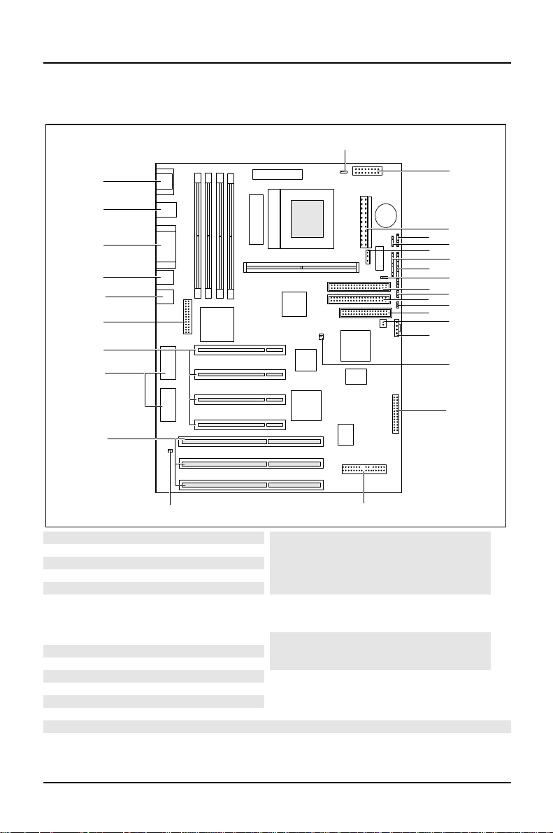
Interfaces and connectors
29
28
27
26
25
24
23
22
21
20
1819
1 = Chipcard reade
2 = Power supply
3 = infrared interface
4 = External loudspeake
5 = Soft-off power supply
6 = LED indicators in front panel
7 = LED indicators in front panel
8 = SCSI-LEDs
9 = IDE drives 3 and 4 (secondary)
10 = Voice modem
11 = IDE drives 1 and 2 (primary)
12 = AUX IN
13 = Floppy disk drive
14 = Remote on via fax/modem
The connectors marked do not have to be present on the system board.
15 = CD Line in
16 = Power on switch
17 = Wavetable board
18 = Game/Midi / Audio
19 = I2C connecto
20 = ISA slots 1-3
21 = Socket for video memory
22 = PCI slots 1-4
23 = Feature board
24 = Video connecto
25 = USB
26 = Parallel port
27 = PS/2 mouse and keyboard port
28 = Serial interface1/2
29 = Fan
11
13
15
1
2
3
4
5
6
7
8
9
10
12
14
16
17
4 A26361-D969-Z120-8-7619
Page 13

Possible screen resolution Introduction
Possible screen resolution
Depending on the operating system used the screen resolutions in the following
table refer to the screen controller on the system board. If you are using an
external screen controller, you will find details of supported screen resolutions in
the Operating Manual or Technical Manual supplied with the controller.
You can set the screen resolution under Windows 95 by selecting Control Panel Display - Settings.
You can set the screen resolution under MS-DOS using the SET-VGA program.
A26361-D969-Z120-8-7619 5
Page 14
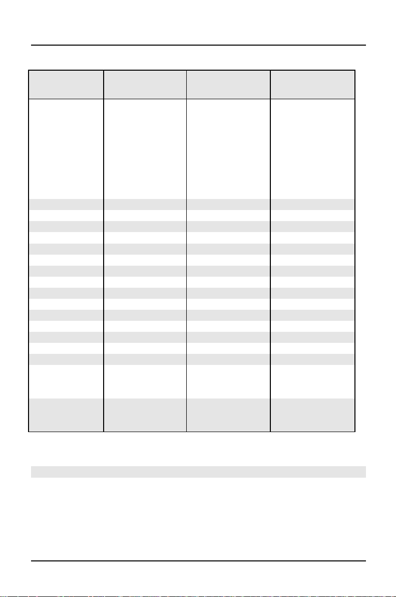
Introduction Possible screen resolution
Screen
resolution
640x350 70 31,5 16
640x350 84 38 16
640x480 60 31,5 16777216
640x480 75 37,5 16777216
640x480 85 43,4 16777216
640x480 100 50,6 16777216
720x400 70 31,5 16
720x400 84 38 16
800x600 60 38 65536
800x600 60 38 16777216
800x600 72 48 65536
800x600 72 48 16777216
800x600 75 47 65536
800x600 75 47 16777216
800x600 85 53,7 65536
800x600 85 53,7 16777216
800x600 100 63 65536
800x600 100 63 16777216
1024x768 87 interlaced 36 256
1024x768 87 interlaced 36 65536
1024x768 60 48,4 256
1024x768 60 48,4 65536
1024x768 75 60 256
1024x768 75 60 65536
1024x768 85 68,7 256 *
1024x768 100 81 256 *
1280x1024 87 interlaced 49 16
1280x1024 87 interlaced 49 256
1280x1024 60 63,7 256 *
1280x1024 75 80,4 256 *
Refresh rate (Hz) Horizontal-
rate (kHz) **
Max. number of
colors
* no 16 color mode
** The horizontal rate values may have a tolerance range of ± 0.3 kHz.
The values marked are only available with a 2-Mbytes video memory.
6 A26361-D969-Z120-8-7619
Page 15
Resource table Introduction
Resource table
assigned
IRQ
Keyboard IRQ1
Serial port COM2 / IrDA IRQ3 02F8, 03F8
Serial interface COM1 / Chip
card reader
Floppy disk drive controller IRQ6 DMA2
Parallel interface LPT1 IRQ7 IRQ5, IRQ7 0278, 0378 DMA1, DMA3
RTC IRQ8
Audio controller
Joystick:
Base address:
MPU 401:
USB controller IRQ11
Mouse controller IRQ12
Numeric processor IRQ13
IDE controller 1 IRQ14
IDE controller 2 IRQ15
IRQ4 03F8, 02F8
Adlib:
possible IRQ Possible
Address
02E8, 03E8
03E8, 02E8
IRQ5, IRQ7,
IRQ9, IRQ10
0200-0207
0220-022F
0240-024F
0260-026F
0280-028F
0300-0301
0330-0331
0338-038B
Possible
DMA
DMA1, DMA3,
DMA5, DMA7
"assigned IRQ" = interrupts assigned as shipped
"Possible IRQ" = these interrupts can be used for your particular application
"Possible address" = this address can be used for your particular application
"Possible DMA" = these DMAs can be used for your particular application
Please note that a resource cannot be used by two applications at the
i
same time.
A26361-D969-Z120-8-7619 7
Page 16

Page 17

Important notes
Store this manual close to the device. If you pass on the device to third parties,
you should also pass on this manual.
Be sure to read this page carefully and note the information before you
!
open the device.
You cannot access the components of the system board without first
opening the device. How to dismantle and reassemble the device is
described in the Operating Manual accompanying the device.
Please note the information provided in the chapter "Safety" in the
Operating Manual of the device.
Incorrect replacement of the lithium battery may lead to a risk of
explosion. It is therefore essential to observe the instructions in the
chapter "Add-on modules" - "Replacing the lithium battery".
The lithium battery must be replaced with an identical battery or a
battery type recommended by the manufacturer (CR2032).
Do not throw lithium batteries into the trashcan. It must be disposed of in
accordance with local regulations concerning special waste.
ADVARSEL
Lithiumbatteri - Eksplosionsfare ved fejlagtig håndtering. Udskiftning må
!
kun ske med batteri af samme fabrikat og type. Lever det brugte batteri
tilbage til leverandøren.
ADVARSEL
Eksplosjonsfare ved feilaktig skifte av batteri. Benytt samme batteritype
!
eller en tilsvarende type anbefalt av apparatfabrikanten. Brukte batterier
kasseres i henhold til fabrikantens instruksjoner.
VARNING
Eksplosionsfara vid felaktigt batteribyte. Använd samma batterityp eller en
!
ekvivalent typ som rekommenderas av apparattillverkarenfabrikanten.
Kassera använt batteri enligt fabrikantens instruktion.
VAROITUS
Paristo voi räjähtää, jos se on virheellisesti asennettu. Vaihda paristo
!
ainoastaan laitevalmistajan suosittelemaan tyyppiin. Hävitä käytetty
paristo valmistajan ohjeiden mukaisesti.
A26361-D969-Z120-8-7619 9
Page 18
Important notes
The shipped version of this board complies with the requirements
of the EEC directive 89/336/EEC "Electromagnetic compatibility".
Compliance was tested in a typical PC configuration.
When installing the board, refer to the specific installation
information in the Operating Manual or Technical Manual of the
receiving device.
Connecting cables for peripherals must be adequately insulated to avoid
interference.
Components can become very hot during operation. Make sure you do
!
not touch components when making extensions to the system board.
There is a danger of burns!
The warranty expires if the device is damaged during the installation or
i
replacement of system expansions. Information on which system
expansions you can use is available from your sales office or the
customer service.
Boards with electrostatic sensitive devices (ESD) may be identified by labels.
When you handle boards fitted with ESDs, you must observe the following points
under all circumstances:
• You must always discharge yourself (e.g. by touching a grounded object)
before working.
• The equipment and tools you use must be free of static charges.
• Pull out the power plug before inserting or pulling out boards containing ESDs.
• Always hold boards with ESDs by their edges.
• Never touch pins or conductors on boards fitted with ESDs.
10 A26361-D969-Z120-8-7619
Page 19

Settings in BIOS Setup
The BIOS Setup menu allows you to set your hardware configuration and system
functions. In addition, the BIOS Setup displays technical information on the PC's
configuration.
When it is supplied, the PC is set to factory default settings which you can alter in
the BIOS Setup menus. You can change these settings in BIOS Setup. Any changes
you make take effect as soon as you save the settings and quit the BIOS Setup.
The Operating Manual describes how to call the BIOS Setup and change menu
entries.
You can select the following settings in the BIOS Setup:
Main - system functions
Advanced - advanced system configuration
Security - security features
Power - power-management features
BIOSFaX - quick start functions
Exit - save and quit
The various menus are described below with all setting options. Since the
i
setting options depend on your PC's hardware configuration, some of
them may not be offered in the BIOS setup.
Main menu - Making system settings
In the Main menu you can set up the following:
• Time (in the field marked System Time)
• Date (in the field marked System Date)
• Floppy disk drive (in the field marked Diskette A or Diskette B)
• Hard disk drive (in the submenus of Hard Disk)
• System boot (in the submenus of Boot Options)
• Display device (in the field marked Video Display)
A26361-D969-Z120-8-7619 11
Page 20
Settings in BIOS Setup Main - system functions
M
Phoenix BIOS Setup
ain Advanced Security Power BIOSFaX Exit
System Time: [07:42:19]
System Date: [08/11/1995]
Diskette A: [1.4M]
Diskette B: [None]
Ê Hard Disk 1: 1 Gbyte
Ê Hard Disk 2: None
Ê Hard Disk 3: None
Ê Hard Disk 4: None
Ê Boot Options
Video Display: [EGA/VGA]
Base Memory: 640K
Extended Memory: 7M
F1 Help ↑↓ Select Item -/+ Change Values F9 Setup Defaults
ESC Exit
Example for Main menu
← → Select Menu Enter Execute Command F7 Previous Values
Item Specific Help
——————————————————————
System Time / System Date
The System Time field and the System Date field show the time and date respectively
according to the PC. The time is shown in the format hh:mm:ss
(hours:minutes:seconds) and the date is shown in the format mm/dd/yyyy
(month/day/year).
If the settings in the System Time and System Date fields are frequently
!
wrong when you power up the computer, the lithium battery is dead.
Change the battery as described in "Add-on modules“ -"Replacing the
lithium battery“).
Diskette A / Diskette B
These two fields are used to specify the type of floppy disk drive installed.
360K, 720K, 1.2M, 1.4M, 2.8M
The entry depends on the floppy disk drive installed.
(Default entry Diskette A : 1.4M).
None A floppy disk drive is not installed.
(Default entry for Diskette B: 1.2M).
12 A26361-D969-Z120-8-7619
Page 21
Main - system functions Settings in BIOS Setup
M
Hard Disk 1 to Hard Disk 4 - Hard disk drive
call the submenu to make corresponding settings of the IDE hard disk drive.
You should change the default settings only if you are connecting an
i
additional IDE drive to one of the two IDE connectors.
The maximum transfer speed is supported independently on all four
IDE drives. Consequently a fast and a slow hard disk drive can be
attached at an IDE connector without affecting the maximum transfer
speed of the fast drive.
The following description of the setting options for Hard Disk 1 also applies to Hard
Disk 2, Hard Disk 3 and Hard Disk 4. The default settings depend on the installed
drive.
Phoenix BIOS Setup
ain
Hard Disk 1: 1 Gbyte Item Specific Help
Autotype Hard Disk: [Press Enter]
Type: [User]
Cylinders: [ 1654]
Heads: [ 16]
Sectors/Track: [ 63]
Write Precomp: [None]
Transfer Mode: [Standard]
LBA Translation: [Enabled]
PIO Mode: [Fast PIO 3]
32 Bit I/O: [Enabled]
F1 Help ↑↓ Select Item -/+ Change Values F9 Setup Defaults
ESC Exit
Example for the submenu Hard Disk 1
A26361-D969-Z120-8-7619 13
← → Select Menu Enter Execute Command F7 Previous Values
Page 22

Settings in BIOS Setup Main - system functions
Autotype Hard Disk
Only if you have installed a new unrecorded IDE hard disk drive, you
!
should mark the AutotypeHard Disk field.
If you have set the hard disk parameters with Autotype Hard Disk, you can
only reduce the values.
If you have installed a new unrecorded IDE hard disk drive, you should mark the
Autotype Hard Disk field and press Enter. This has the effect of setting the optimum
values for the IDE hard disk drive. You can change these values if you set the Type
field to User.
Type - Hard Disk Type
This field is used to specify the type of hard disk drive.
None You cannot change the hard disk parameters (Cylinders, Heads,
Sector/Track and Write Precomp). An IDE drive has not been
installed.
1 to 39 The hard disk parameters (Cylinders, Heads, etc.) are preset.
Auto If the hard disk supports this mode, the setup menu reads the hard
disk parameters from the disk itself. You do not need to select the
parameters yourself.
User You can enter the hard disk parameters (Cylinders, Heads etc.)
yourself.
If you have set the hard disk parameters with Autotype Hard Disk,
you can only reduce the values.
Examples of user-defined entries (IDE drives):
Hard disk hard disk capacity
parameter 850 Mbyte 1,2 Gbyte 1,6Gbyte
Cylinders 1654 2484 3148
Heads 16 16 16
Sectors 63 63 63
Write Precomp None None None
14 A26361-D969-Z120-8-7619
Page 23

Main - system functions Settings in BIOS Setup
Cylinders, Heads, Sectors/Track, Write Precomp - hard disk parameter
These hard disk parameters are set in accordance with the IDE hard disk drive. If
you want to change the hard disk parameters manually, set the Type field to User.
Transfer Mode
This field specifies the transfer mode for the IDE hard disk drive.
Standard One block is transferred for each interrupt (default entry).
2 Sectors, 4 Sectors, 6 Sectors, 8 Sectors, 16 Sectors
The set number of blocks (sectors) is transferred for each interrupt.
LBA Translation - Addressing
This field enables and disables the LBA (Logical Block Addressing) mode. LBA
mode allows you to install and use IDE hard disks with a capacity of more than 528
Mbytes. If a hard disk supports LBA mode, you can use the full capacity of the IDE
hard disk.
The default entry depends on the installed IDE hard disk drive. Change the default
entries only if you are installing another hard disk drive.
You may only use IDE drives in the LBA mode selected when they were
!
set up. In other words, if you set up a hard disk with LBA mode disabled,
you may only operate the hard disk with LBA mode disabled.
Enabled If the hard disk supports LBA and it has a capacity of more than
528 Mbytes, the BIOS translates the hard disk parameters,
allowing the disk's full capacity to be used. This allows the disk's
full capacity to be used.
If the hard disk does not support LBA, its parameters are not
translated.
Disabled The BIOS uses the hard disk parameters and supports a maximum
capacity of 528 Mbytes.
A26361-D969-Z120-8-7619 15
Page 24

Settings in BIOS Setup Main - system functions
M
PIO Mode - Transfer rate
The PIO (Programmed Input Output) Mode defines the transfer rate of the IDE
hard disk drive.
Standard 0.8 Mbyte/s to 2 Mbytes/s (default entry)
Fast PIO 1 2 Mbytes/s to 4 Mbytes/s
Fast PIO 2 4 Mbytes/s to 5 Mbytes/s
Fast PIO 3 5 Mbytes/s to 10 Mbytes/s
Fast PIO 4 more than 10 Mbyte/s
32 Bit I/O - Bus width for data transfer
This field specifies the width of data transmission between the processor and the
IDE controller.
Enabled The data transfer is 32 bits in width at the PCI bus. This enhances
performance (default entry).
Disabled The data transfer is 16 bits in width.
Boot Options
calls the submenu in which you can select the settings for system startup of the
PC.
Phoenix BIOS Setup
ain
Boot Options Item Specific Help
POST Error Halt: [Halt On All Errors]
Quick Boot: [Disabled]
Quiet Boot: [Disabled]
Boot Sequence: 1. Diskette
F1 Help ↑↓ Select Item -/+ Change Values F9 Setup Defaults
ESC Exit
Example for submenu Boot Options
← → Select Menu Enter Execute Command F7 Previous Values
16 A26361-D969-Z120-8-7619
2. Hard Disk
3. CD ROM
Page 25

Main - system functions Settings in BIOS Setup
POST Error Halt - Aborting system startup
defines whether the system startup is to be aborted and the system halted when
an error is detected.
Halt On All Errors
If the self-test detects an error, system startup is aborted after the
self-test, and the system is halted (default entry).
No Halt On Any Errors
The system startup is not aborted. The error is ignored as far as
possible. The error is ignored as far as possible.
Quick Boot
can reduce the extent of the self-test and thus accelerate the system startup.
Enabled When the PC is switched on, the quick self-test is carried out, in
which the floppy disk drives are not checked.
Disabled When the PC is switched on, the complete PC configuration is
tested (default entry).
Quiet Boot
Instead of a start information a logo is displayed on the screen.
Enabled The logo is displayed on the screen. A switch to the start
information is made if you press the [Esc]
[Esc] key or if errors occur.
[Esc][Esc]
Disabled The start information is displayed on the screen (default entry).
A26361-D969-Z120-8-7619 17
Page 26

Settings in BIOS Setup Main - system functions
Boot Sequence
defines the sequence in which the system BIOS searches the drives for system
files to start the operating system. If you wish to change this sequence, place the
cursor on the entry for the drive which you wish to move forward ([+]
([-]
[-] key).
[-][-]
Default entry:
1. 1. Diskette
2. Hard Disk
3. CD ROM
[+] key) or back
[+][+]
Video Display
This field is used to specify the type of monitor connected.
EGA/VGA, Color 80, Monochrome
Default entry: EGA/VGA
Base Memory
This field indicates the size of the available base memory below 1 Mbyte.
Extended Memory
indicates the size of the memory above 1 Mbyte.
18 A26361-D969-Z120-8-7619
Page 27

Advanced - Advanced system configuration Settings in BIOS Setup
A
Advanced menu - Making advanced system settings
Change the default settings only for special applications. Incorrect
!
settings can cause malfunctions.
You can make the following system settings in the Advancedmenu:
• Internal cache and second-level cache (in the Cache Memory submenu)
• Copy BIOS sections to the RAM (in the Shadow Memory submenu)
• Interfaces and controllers (in the PeripheralConfiguration submenu)
• PCI functionality (in the PCI Configuration submenu)
• System settings (in the Advanced System Configuration submenu)
• Plug&Play functionality (in the Plug and Play O/S field)
• Configuration data (in the Reset Configuration Data field)
• Hard disk access (in the Large Disk Access Mode field)
Phoenix BIOS Setup
Main
dvanced Security Power BIOSFaX Exit
Setting items on this menu to incorrect
values
may cause your system to malfunction.
Ê Cache Memory
Ê Shadow Memory
Ê Peripheral Configuration
Ê PCI Configuration
Ê Advanced System Configuration
Plug & Play O/S: [Yes]
Reset Configuration Data: [No]
Large Disk Access Mode: [DOS]
F1 Help ↑↓ Select Item -/+ Change Values F9 Setup Defaults
ESC Exit
Example for the Advanced menu
A26361-D969-Z120-8-7619 19
← → Select Menu Enter Execute Command F7 Previous Values
Warning!
Item Specific Help
——————————————————————
Page 28

Settings in BIOS Setup Advanced - Advanced system configuration
A
Cache Memory
calls the submenu in which you can make the settings for the internal cache (in the
processor) and the second-level cache (on the system board).
Phoenix BIOS Setup
Cache: [Intern And Extern]
Cache Mode: Write Back
Cache System BIOS Area: [Enabled]
Cache Video BIOS Area: [Enabled]
Cache Memory Regions:
C800 - CBFF: [Disabled]
CC00 - CFFF: [Disabled]
D000 - D3FF: [Disabled]
D400 - D7FF: [Disabled]
D800 - DBFF: [Disabled]
DC00 - DFFF: [Disabled]
F1 Help ↑↓ Select Item -/+ Change Values F9 Setup Defaults
ESC Exit
Example for submenu Cache Memory
dvanced
Cache Memory Item Specific Help
← → Select Menu Enter Execute Command F7 Previous Values
Cache - cache utilization
This field switches the cache on and off. The cache is a buffer to which parts of the
main memory and BIOS can be temporarily copied. ThePC's performance is
higher when the cache is switched on.
You must disable the cache, if the access time is too short for older applications.
Intern Only Only the internal cache is used.
Intern And Extern
Internal (first-level cache) and external cache (second-level cache)
are enabled. If there is no external Cache, only the internal cache
is used.
Disabled Internal (first-level cache) and external cache (second-level cache)
are disabled. All cache-related settings are then without effect.
20 A26361-D969-Z120-8-7619
Page 29

Advanced - Advanced system configuration Settings in BIOS Setup
Cache Mode - Transfer Mode
Requirement: The Cache field must be set to Intern Only or Intern And Extern.
Cache Mode sets the mode in which the CPU uses the cache. The field is set to
Write Back and can not be changed
In write-back mode the CPU writes information to the cache. The information is
only written to the main memory if necessary. Main memory and cache contents
are not identical.
Cache System BIOS Area / Cache Video BIOS Area
The Cache field must be set to Internonly or Intern and Extern.
Cache System BIOS Area and Cache Video BIOS Area lets you specify the BIOS that
should be mapped to the cache. Mapping the BIOS to the cache increases system
performance.
Enabled The specified BIOS is mapped to the cache (default entry).
Disabled The specified BIOS is not mapped to the cache.
Cache Memory Regions
The Cache field must be set to Internonly or Intern and Extern.
Cache Memory Regions lets you specify the BIOS ROM areas that should be
mapped to the cache. Mapping the BIOS ROM areas to the cache increases
system performance.
Enabled The relevant ROM area is mapped to the cache.
Disabled The relevant ROM area is not mapped to the cache (default entry).
If your ISA board uses a dual ported RAM in the associated ROM area,
!
set the entry to Disabled.
A26361-D969-Z120-8-7619 21
Page 30

Settings in BIOS Setup Advanced - Advanced system configuration
A
Shadow Memory
calls the submenu in which you can specify which parts of the ROM (Read Only
Memory) are to be copied to the faster RAM (Random Access Memory) at system
startup.
Phoenix BIOS Setup
System Shadow: Enabled
Video Shadow: [Enabled]
Shadow Memory Regions:
F1 Help ↑↓ Select Item -/+ Change Values F9 Setup Defaults
ESC Exit
Example for submenu Shadow Memory
dvanced
Shadow Memory Item Specific Help
C800 - CBFF: [Disabled]
CC00 - CFFF: [Disabled]
D000 - D3FF: [Disabled]
D400 - D7FF: [Disabled]
D800 - DBFF: [Disabled]
DC00 - DFFF: [Disabled]
← → Select Menu Enter Execute Command F7 Previous Values
System Shadow
This field is always Enabled, because the System BIOS is automatically copied to
the faster RAM.
Video Shadow
This field allows you to copy the video BIOS to fast RAM. Copying the video BIOS
to fast RAM increases system performance.
Enabled The video BIOS is copied to fast RAM (default entry).
Disabled The video BIOS is not copied to fast RAM. This setting is not
effective with an external screen controller connected to the PCI
bus.
22 A26361-D969-Z120-8-7619
Page 31

Advanced - Advanced system configuration Settings in BIOS Setup
A
Shadow Memory Regions - ROM areas
Shadow Memory Regions allows you to copy ROM areas to fast RAM. Copying ROM
areas to fast RAM increases system performance.
Enabled The ROM area is copied to fast RAM.
Disabled The ROM area is not copied to fast RAM (default entry).
If your ISA board uses a dual ported RAM in the associated ROM area,
!
set the entry to Disabled.
Peripheral Configuration - Ports and Controllers
calls the submenu in which you can set the ports and controllers.
Phoenix BIOS Setup
dvanced
Peripheral Configuration Item Specific Help
Serial 1: [Auto]
Serial 2: [Auto]
Serial 2 Mode: [Standard]
Parallel: [Auto]
Parallel Mode: [Printer]
Diskette Controller: [Enabled]
Hard Disk Controller: [Primary And
Secondary]
Mouse Controller: [Enabled]
Audio Controller: [Enabled]
USB Controller: [Disabled]
F1 Help ↑↓ Select Item -/+ Change Values F9 Setup Defaults
ESC Exit
Example for submenu Peripheral Configuration
A26361-D969-Z120-8-7619 23
← → Select Menu Enter Execute Command F7 Previous Values
Page 32

Settings in BIOS Setup Advanced - Advanced system configuration
Serial 1 / Serial 2 - Serial ports
This field selects the address and the interrupt used to access the relevant serial
port.
3F8h, IRQ4, 2F8h, IRQ3, 3E8h, IRQ4, 2E8h, IRQ3,
The serial port is set to the shown address and interrupt.
Auto The serial interface is automatically set to the next available
combination (address, interrupt) (Default entry).
Disabled The serial port is disabled.
Serial 2 Mode - Serial interfaces
This field defines whether the second serial port is used as the standard port or as
the infrared interface.
If you wish to use infrared data transfer, an infrared port with the associated
hardware must be incorporated in the device.
Standard The port operates as a serial port (default entry).
IRDA (Infra-Red Data Association) The serial port permits infrared data
transfer up to 115 kbit/s. External serial port 2 does not function.
Parallel - parallel port
This field selects the address and the interrupt used to access the parallel port.
378h, IRQ7, 278h, IRQ5, 3BCh, IRQ7
The parallel port is set to the shown address and interrupt.
Auto The parallel interface is automatically set to the next available
combination (address, interrupt) (Default entry).
Disabled The parallel port is disabled.
24 A26361-D969-Z120-8-7619
Page 33

Advanced - Advanced system configuration Settings in BIOS Setup
Parallel Mode - Parallel data transfer
This field is used to specify whether the parallel port is to be used as a bidirectional input/output port or just as an output port. ECP and EPP transfer modes
allow faster transfer rates of 2 and 2.4 Mbytes/s. These modes will only work with
peripheral devices which support them. In addition, the field Parallel must be set to
378h or 278h.
Printer The port functions as an output port only (default entry).
Bidirection Data can be transferred in both directions across the port.
EPP Fast transfer mode (up to 2 Mbytes/s), can output and receive
data. The mode requires a peripheral device which supports the
EPP (Enhanced Parallel Port) transfer mode.
ECP Fast transfer mode (up to 2.4 Mbytes/s), can output and receive
data. The mode requires a peripheral device which supports the
ECP (Enhanced Capability Port) transfer mode. The DMA channel
required is determined by the system in accordance with Plug &
Play.
Diskette Controller
This field is used to enable and disable the built-in floppy disk controller on the
system board.
Enabled The floppy disk controller is enabled - IRQ 6 is used. (default
entry).
Disabled The floppy disk controller is disabled - IRQ 6 is free.
Hard Disk Controller
This field allows you to enable and disable the built-in IDE hard disk controller. The
associated interrupts (IRQ 14 for the first connector, IRQ 15 for the second
connector) will only be available if no IDE hard disk drive is physically connected.
A26361-D969-Z120-8-7619 25
Page 34

Settings in BIOS Setup Advanced - Advanced system configuration
Primary The first IDE hard disk controller is enabled (default entry). Two
IDE drives can be attached to the first (primary) connector. IRQ14
is occupied.
Primary And Secondary
Primary and secondary IDE drive controllers are activated (default
entry). Up to four IDE drives can be connected. Low-speed drives
are preferred for the second (secondary) connector (e.g. CDROM). IRQ14 and IRQ15 are occupied.
Disabled Both IDE hard disk controllers are disabled.
Mouse Controller
This field is used to enable and disable the built-in mouse controller on the system
board.
Enabled The mouse controller is enabled (default entry)- IRQ 12 is used. .
Disabled The mouse controller is disabled - IRQ 12 is free.
Audio Controller
This field sets the base address for the audio controller on the system board or
disables the audio controller.
Enabled The system BIOS determines which system resources (interrupts,
addresses, DMAs) are occupied (default entry).
Disabled The audio controller is disabled.
USB Controller
switches the USB controller (Universal Serial Bus) of the system board on or off.
Enabled The system BIOS determines which system resources (interrupts,
addresses) are occupied.
Disabled The USB controller is disabled (default entry).
26 A26361-D969-Z120-8-7619
Page 35

Advanced - Advanced system configuration Settings in BIOS Setup
A
PCI Configuration
calls the submenu in which you can make the settings for the PCI slots.
Phoenix BIOS Setup
dvanced
PCI Configuration Item Specific Help
PCI Interrupt Mapping INTA#: [Auto]
PCI Interrupt Mapping INTB#: [Auto]
PCI Interrupt Mapping INTC#: [Auto]
PCI Interrupt Mapping INTD#: [Auto]
VGA Interrupt: [Disabled]
PCI Device, Slot #1
Default Latency Timer: [Yes]
Latency Timer: [0040]
PCI Device, Slot #2
Default Latency Timer: [Yes]
Latency Timer: [0040]
PCI Device, Slot #3
Default Latency Timer: [Yes]
Latency Timer: [0040]
F1 Help ↑↓ Select Item -/+ Change Values F9 Setup Defaults
ESC Exit
← → Select Menu Enter Execute Command F7 Previous Values
Example for submenu PCI Configuration
A26361-D969-Z120-8-7619 27
Page 36

Settings in BIOS Setup Advanced - Advanced system configuration
PCI Interrupt Mapping INTx# - Assignment of the PCI interrupts
defines which PCI interrupt is switched to which ISA interrupt. For the change to
take effect, you must switch your device off and then on again after the Setup BIOS
has terminated.
A multifunctional PCI board can use all PCI interrupts, if need be.
If you use a setting other than Auto, the Plug&Play functionality of the system BIOS
for PCI boards is deactivated.
The PCI interrupts INTA#, INTB# and INTC# are assigned as follows:
PCI slot 1 = INTA#, PCI slot 2 = INTB#,
PCI slot 3 = INTC#, PCI slot 4 = INTD#
Auto The PCI interrupts are assigned automatically in accordance with
the Plug&Play guidelines (default entry).
Disabled No PCI interrupt is used for the PCI board in the assigned PCI
slot.
IRQ03, IRQ04, IRQ05, IRQ06, IRQ07, IRQ09, IRQ10, IRQ11, IRQ12, IRQ14, IRQ15
The PCI interrupt is switched to the selected ISA interrupt. You
may not select an ISA interrupt that is used by a component on the
system board (e.g. controller) or an ISA board.
VGA Interrupt - Assigning PCI-VGA interrupt
assigns PCI interrupt to the screen controller on the built-in PCI board. If you have
not defined any other interrupt with PCI Interrupt Mapping, IRQ9 is assigned.
Enabled The interrupt is assigned to the screen controller on the built-in PCI
board (default entry).
Disabled The interrupt can be used for other add-on boards.
28 A26361-D969-Z120-8-7619
Page 37

Advanced - Advanced system configuration Settings in BIOS Setup
A
PCI Device, Slot #n: Default Latency Timer
specifies the lowest number of clock cycles in which a PCI master board can be
active at the PCI bus; n stands for the number of the PCI slot. For the change to
take effect, you must switch your device off and then on again after the BIOS Setup
has terminated.
Yes The value predefined by the PCI board is accepted. The entry in
the corresponding field for PCI Device, Slot #n: Latency Timer is
ignored
No The value predefined by the PCI board is ignored. The value set in
the relevant field of PCI Device, Slot #n: Latency Timer determines
the number of clock cycles.
PCI Device, Slot #n: Latency Timer
Requirement: The relevant field of PCI Device, Slot #n: Default Latency Timer must be
set to No.
The field defines the lowest number of clock cycles in which a burst can be
transferred on the PCI bus. n stands for the number of the PCI slot.
0000h to 0280h Number of clock cycles (default entry = 0040h).
Advanced System Configuration
calls the submenu in which you can make additional settings.
Phoenix BIOS Setup
dvanced
Advanced System Configuration Item Specific Help
ISA Memory Gap: [Disabled]
Parity Mode: [Disabled]
System Performance: [Fast]
Feature Connector: [Disabled]
F1 Help ↑↓ Select Item -/+ Change Values F9 Setup Defaults
ESC Exit
Example for submenu Advanced System Configuration
A26361-D969-Z120-8-7619 29
← → Select Menu Enter Execute Command F7 Previous Values
Page 38

Settings in BIOS Setup Advanced - Advanced system configuration
ISA Memory Gap
inserts a contiguous ISA memory area of 1 Mbyte into the main memory area of 15
to 16 Mbytes.
Enabled The ISA memory area is inserted.
Disabled The ISA memory area is not inserted (default).
Parity Mode - DRAM Parity Check
Determines whether a parity check is carried out in the case of DRAM modules. If
the system BIOS detects that at least one DRAM module does not have a parity
bit, the parity check is generally disabled.
Disabled No parity check is performed.
Parity The parity check is set in parity mode. A bit corruption is
recognized and an error message is issued (default entry).
ECC A bit corruption is corrected (no error message). An error message
is issued for two or more bit corruptions.
System Performance - System Speed
Determines whether system timing is with default parameters or parameters which
allow a better performance.
Standard System is set to standard.
Fast Setting performance of system (default entry).
Feature Connector - Enabling of Feature Connectors
This field is used to enable and disable the feature connector on the system board.
Enabled The feature connector is enabled.
Disabled The feature connector is disabled (default entry).
30 A26361-D969-Z120-8-7619
Page 39

Advanced - Advanced system configuration Settings in BIOS Setup
Plug & Play O/S
defines the Plug&Play functionality. Plug&Play means that inserted modules are
automatically recognized and installed if they support Plug&Play.
Yes The operating system takes over some of the Plug&Play functions.
You should select this setting only if the operating system supports
Plug&Play.
No The BIOS takes over the complete Plug&Play functionality (default
setting).
Reset Configuration Data
This field specifies whether the configuration data is reset and reinitialized when
the PC is started.
Yes When the PC is started the old configuration data is reset and the
entry in this field is set to NO. The new configuration data is
determined by means of the Plug&Play functionality. The mounted
modules and drives are then initialized with this data.
No The Plug&Play functionality ascertains the current configuration
data and uses it to initialize the installed modules and drives. There
is no update when the system is started (default entry).
Large Disk Access Mode - Hard disk access
specifies the type of hard disk access for large hard disks (more than 1024
cylinders, 16 heads). The default setting depends on the operating system used.
DOS the operating system uses MS-DOS-compatible hard disk
accesses.
Other Ifthe operating system uses hard disk accesses which are not MS-
DOS-compatible (e.g. Novell, SCO Unix).
A26361-D969-Z120-8-7619 31
Page 40

Settings in BIOS Setup Security - security features
y
Menu Security - Setting up the security features
You can set up the following security features in the Security menu:
• Protecting BIOS Setup (in the field marked Set Setup Password)
• Protecting BIOS of add-on modules (in the field marked Setup Password Lock)
• Protecting system boots (in the field marked Set System Password)
• Locking input devices (in the field marked System Password Mode)
• Prevention of system boots from floppy disk (in the field marked System Load)
• Displaying Setup message (in the Setup Prompt field)
• Virus Warning (in the field marked Virus Warning)
• Prevention of write operations to floppy disk (in the field marked Diskette Write)
• Write protection of System BIOS (in the field marked Flash Write)
• On/Off functionality (in the submenu Power On/Off)
Phoenix BIOS Setup
Main Advanced
Setup Password Not Installed
System Password Not Installed
Set Setup Password: [Press Enter]
Setup Password Lock: [Standard]
Set System Password: [Press Enter]
System Password Mode: [System]
System Load: [Standard]
Setup Prompt: [Enabled]
Virus Warning: [Disabled]
Diskette Write: [Enabled]
Flash Write: [Enabled]
Ê Power On/Off
F1 Help ↑↓ Select Item -/+ Change Values F9 Setup Defaults
ESC Exit
Example for Security menu
← → Select Menu Enter Execute Command F7 Previous Values
Securit
Power BIOSFaX Exit
Item Specific Help
——————————————————————
Setup Password / System Password
These fields indicate whether the appropriate password is installed or not.
32 A26361-D969-Z120-8-7619
Page 41

Security menu - Setting up the security features Settings in BIOS Setup
Set Setup Password
This field enables you to install the setup password. The setup password prevents
unauthorized callup of the BIOS setup.
Mark the field and press the Return key. You can then enter and confirm the setup
password (see also the PC Operating Manual).
Setup Password Lock
specifies the effect of the Setup Password. The setting in this field takes effect as
soon as a Setup Password has been installed.
Standard The setup password prevents unauthorized callup of the BIOS setup
(Default entry).
Extended The Setup Password prevents unauthorized calls of the BIOS Setup
and locks the keyboard when the PC is initialized. This prevents
unauthorized access to settings for installed boards with a BIOS of
their own.
Set System Password
Requirement: The setup password is installed.
This field enables you to install the system password. The system password
prevents unauthorized access to your system.
Mark the field and press the Return key. You can then enter and confirm the
system password (see also the PC Operating Manual).
A26361-D969-Z120-8-7619 33
Page 42

Settings in BIOS Setup Security - security features
System Password Mode
specifies the effect of the system password. The setting in this field becomes
effective as soon as a system password is installed.
System When the PC is started, the system password enables the
operating system to be booted.
Keyboard Whenthe PC is started, the operating system is booted and the
keyboard and mouse are locked. The system password unlocks the
keyboard and mouse.
System Load
This field specifies the drive from which the operating system can be loaded.
Standard The operating system can be loaded from floppy disk or hard disk
(default entry).
Diskette Lock The operating system can only be loaded from hard disk.
Setup Prompt - Setup message
specifies whether the setup message Press F2 to enter SETUP is displayed
when the system is rebooted.
Enabled The setup message Press F2 to enter SETUP is displayed
when the system is started (default entry).
Disabled The setup message is not displayed.
34 A26361-D969-Z120-8-7619
Page 43

Security menu - Setting up the security features Settings in BIOS Setup
Virus Warning
This field checks the boot sectors of the hard disk drive to see if any changes have
been made since the previous system startup. If they have been changed and the
reason for this is unknown, a program for finding computer viruses should be
loaded.
Enabled If the boot sector has been changed since the previous system
startup (e.g. new operating system or virus attack), a warning is
displayed. The warning stays on the screen until you acknowledge
the changes with Confirm or deactivate the function (Disabled).
Confirm This entry confirms a required change in a boot sector (e.g. new
operating system).
Disabled The boot sectors are not checked (default entry).
Diskette Write
This field is used to enable and disable floppy disk write-protection.
Enabled Floppy disks can be read, written or deleted, the write protection in
BIOS setup must be disabled (switch 8 off, default entry).
Disabled The diskettes can only be read.
Flash Write
This field can assign write protection to the System BIOS.
Enabled The System BIOS can be written or deleted. BIOS update from
floppy disk is possible (default entry).
Disabled The System BIOS can neither be written to nor deleted. BIOS
update from floppy disk is not possible
A26361-D969-Z120-8-7619 35
Page 44

Settings in BIOS Setup Security - security features
y
Power On/Off
calls the submenu in which you can specify how the system can be powered on
and off. These settings cause the to be switched on and off in the same way as
using the on/off button on the system unit. The on/off button is always operable
and cannot be disabled.
Securit
Power On/Off Item Specific Help
Power Off Source
Software: [Enabled]
Keyboard: [Enabled]
Power On Source
Remote: [Enabled]
Keyboard: [Enabled]
Timer: [Enabled]
Chipcard: [Enabled]
F1 Help ↑↓ Select Item -/+ Change Values F9 Setup Defaults
ESC Exit
Example for submenu Power On/Off
← → Select Menu Enter Select Ê Sub-Menu F7 Previous Values
Phoenix BIOS Setup
If you have assigned a system password in System Mode, the boot
!
procedure is suspended during remote power on of the system (using
Remote Power On or Timer On) as the system waits for entry of the system
password. For this reason you should not assign a system password in
System Mode if you want to use remote power-on.
Power Off Source: Software
specifies whether the system can be switched off with a program (DeskOff, SWOFF)
or an operating system (Windows 95, Windows NT with Siemens HAL).
Enabled The system can be switched off with the SWOFF program (default
entry).
Disabled The system cannot be switched off with a program.
36 A26361-D969-Z120-8-7619
Page 45

Security menu - Setting up the security features Settings in BIOS Setup
Power Off Source: Keyboard
specifies whether the system can be switched off using a special on/off button on
the keyboard.
Enabled The system can be switched off using a special on/off button on the
keyboard.
Disabled The system cannot be switched off using a special on/off button on
the keyboard (default).
Power On Source: Remote
specifies whether the system can be switched on by an incoming message (e. g.
modem). The signal can be supplied externally via serial interface 1 or internally
via the remote on connector.
Enabled The system can be switched on from an incoming message
(default entry).
Disabled The system cannot be switched on from an incoming message.
Power-on Source: Keyboard
specifies whether the system can be switched on using a special on/off button on
the keyboard.
Enabled The system can be switched on using a special on/off button on the
keyboard (default entry).
Disabled The system cannot be switched on using a special on/off button on
the keyboard.
A26361-D969-Z120-8-7619 37
Page 46

Settings in BIOS Setup Security - security features
Power-on Source: Timer
specifies whether the system can be timed to switch on at a particular time or after
a particular period of time.
The switch-on time cannot be specified in BIOS Setup. You require a suitable
program for setting this switch-on time.
Enabled The system can be switched on at set times.
Disabled The system cannot be switched on under timer control (default
entry).
Rebooting after a critical system error (ASR&R Boot Delay field in the
!
Server menu) is not affected by this setting.
Chipcard
specifies whether the system can be switched on via the chipcard reader.
Enabled The system can be switched on via the chipcard reader (default).
(Default entry.)
Disabled The system cannot be switched on via the chipcard reader.
38 A26361-D969-Z120-8-7619
Page 47

Power - power-management features Settings in BIOS Setup
Power menu - Setting energy saving functions
Programs for power management (e.g. POWER.EXE) can change the settings for
the energy saving functions.
You can set the following functions in the Power menu:
• Enabling of APM interface (in the Advanced Power Management field)
• Extent of energy saving functions (in the Power Management Mode field)
• Standby mode (in the Standby Timeout field)
• Suspend mode (in the Suspend Timeout field)
• Hard disk energy saving functions (in the Hard Disk Timeout field)
• Processor speed in standby mode (in the StandbyCPU Speed field)
• Save system status (in the Save To Disk field)
• Defining system activities (in the Wakeup Event field)
Phoenix BIOS Setup
Main Advanced Security
APM [Enabled]
Power Management Mode: [Customize]
Standby Timeout: [15 min]
Suspend Timeout: [10 min]
Hard Disk Timeout: [10 min]
Standby CPU Speed: [Medium]
Save To Disk: [Disabled]
Ê Wakeup Event
F1 Help ↑↓ Select Item -/+ Change Values F9 Setup Defaults
ESC Exit
Example for menu Power
← → Select Menu Enter Execute Command F7 Previous Values
Power BIOSFaX Exit
Item Specific Help
——————————————————————
APM - Enabling the APM Interface
Determines whether an operation system can change the power management
settings in the system BIOS.
Enabled The operating system has access to the power management
settings and can change these if necessary (default entry).
Disabled Changes can not be made to power management setting by an
operating system.
A26361-D969-Z120-8-7619 39
Page 48

Settings in BIOS Setup Power - power-management features
Power Management Mode - Extent of energy saving functions
This field defines the extent of the energy saving functions.
Customize The functions set in the fields Standby Timeout, Hard Disk Timeout
and Standby CPU Speed are effective in power management.
(Default entry).
Maximum, Medium or Minimum Power Savings
These entries call predefined settings, thus determining the extent
of energy saving.
Disabled None of the energy saving functions is effective.
Standby Timeout
Requirement: The Power Management Mode must be set to Customize.
This field defines the amount of time without system activity the PC is to wait
before switching to standby mode. In standby mode, the screen is dark and the
processor clock is set in accordance with the entry in the Standby CPU Speed field.
The next wakeup event terminates standby mode again
2 min, 5 min, 10 min, 15 min, 30 min
Default entry = 15 min.
Disabled The PC does not switch to standby mode.
Suspend Timeout - Suspend mode
Requirement: The Power Management Mode must be set to Customize.
This field defines the amount of time without system activity the system is to wait
before switching to standby mode. In standby mode, the screen is dark and the
processor is switched off.
The next wakeup event terminates suspend mode again.
In a network environment Suspend Timeout must be disabled, otherwise data
transfer will be aborted.
2 min, 15 min, 30 min, 1 Std, 2 Std, 3 Std, 4 Std
Default entry = 15 min.
Disabled The PC does not switch to suspend mode
40 A26361-D969-Z120-8-7619
Page 49

Power - power-management features Settings in BIOS Setup
Hard Disk Timeout
Requirement: The Power Management Mode must be set to Customize.
This field defines the amount of time without system activity before the motor of the
hard disk drive is switched off. As soon as there is a hard disk access, the motor is
switched back on.
2 min, 5 min, 10 min, 15 min
Default entry = 10 min.
Disabled The PC does not switch off the hard disk drive.
Standby CPU Speed
Requirement: The Power Management Mode must be set to Customize.
This field specifies the processor's clock speed in standby mode. The entries High,
Medium and Low cause programs to run more slowly.
In a network environment the processor's clock speed must be set to Max,
otherwise data transfer will take place at reduced speed.
Max Maximum clock speed
High 1/4 of maximum clock speed
Medium 1/8 of maximum clock speed (default entry )
Low 1/16 of maximum clock speed
Save To Disk
Requirement: The Power Management Mode must be set to Customize. There must
be sufficient storage space on the hard disk.
This field specifies whether the current system status (active programs, files,
memory contents) is saved to file SAVETO.DSK when the system switches to
suspend mode. This system status is restored when you restart the system; in
other words, you can carry on working in the same application.
Enabled The contents of the main memory, working memory, video memory
and cache are saved to the hard disk.
Disabled The memory contents are not saved (default entry).
A26361-D969-Z120-8-7619 41
Page 50

Settings in BIOS Setup Power - power-management features
The Enabled setting only works with:
• Controllers integrated on the system board (e. g. graphics and audio
controllers)
• Add-on boards indicated in the price list.
Other add-on boards are not supported at present.
Do not set the entry in the Save to Disk field to Enabled, if you are using
!
boards other than those listed above. This applies, for example, to add-on
boards such as SCSI controllers and graphics controllers.
These restrictions also apply if you activate the Quickstart function (Save
to disk) under Windows using DeskEnergy.
Before starting the Save to Disk function, you should first close all
documents located on network drives.
42 A26361-D969-Z120-8-7619
Page 51

Power - power-management features Settings in BIOS Setup
Wakeup Event - Defining system activities
This field calls the submenu in which you can set the interrupts which are to be
evaluated as system activities. When one of these interrupts occurs, the active
energy saving mode is terminated, for example.
In a network environment the Wakeup Event for the network controller interrupt must
be disabled, otherwise the system will not switch to Standby Mode.
Phoenix BIOS Setup
Power
Wakeup Event Item Specific Help
IRQ 1: Enabled
IRQ 3: [Disabled]
IRQ 4: [Disabled]
IRQ 5: [Disabled]
IRQ 6: [Enabled]
IRQ 7: [Disabled]
IRQ 8: [Disabled]
IRQ 9: [Disabled]
IRQ 10: [Disabled]
IRQ 11: [Disabled]
IRQ 12: [Enabled]
IRQ 13: Disabled
IRQ 14: [Enabled]
IRQ 15: [Enabled]
F1 Help ↑↓ Select Item -/+ Change Values F9 Setup Defaults
ESC Exit
← → Select Menu Enter Select Ê Sub-Menu F7 Previous Values
Example for Wakeup Event submenu
Enabled The associated interrupt is evaluated as a system activity.
Disabled The associated interrupt has no effect on the active energy saving
mode.
A26361-D969-Z120-8-7619 43
Page 52

Settings in BIOS Setup BIOSFaX - quick start functions
BIOSFaX menu - modem - quick start functions
With the BIOSFaX menu you can select whether your system can be switched on
via modem and whether an abbreviated system startup is executed. During this
system startup any incoming call or fax is stored.
Phoenix BIOS Setup
Main Advanced Security Power
Receive Mode: [Disabled]
Ring Count: [Auto]
Fax Tone Count: [Auto]
Fax Modem Port: COM3
F1 Help ↑↓ Select Item -/+ Change Values F9 Setup Defaults
ESC Exit
Example for BIOSFaX menu
← → Select Menu Enter Select Ê Sub-Menu F7 Previous Values
BIOSFaX Exit
Item Specific Help
——————————————————————
Receive Mode
Requirement: Remote on functionality (Remote on) must be enabled.
This field determines the mode in which the modem is operated. Depending on the
setting, any incoming message will be recorded.
Voice and Fax Any incoming call or fax will be recorded.
Voice Only an incoming call will be recorded.
Fax Only an incoming fax will be recorded.
Disabled Modem functionality is not available when the system is switched
off (default entry).
Ring Count
Defines how often a ring tone should sound before the modem answers. Possible
settings: 2, 3, 4, 5, 6, 7 or Auto (default entry).
44 A26361-D969-Z120-8-7619
Page 53

BIOSFaX - quick start functions Settings in BIOS Setup
Fax Tone Count
Defines how often a fax tone should sound before the modem answers. Possible
settings: 1, 2, 3, 4, 5, 6, 7 or Auto (default entry).
Fax Modem Port - Serial port
Shows which serial interface is used for the modem. Thissetting is assigned by the
system and cannot be changed.
Possible displays: COM1, COM2, COM3 or COM4.
A26361-D969-Z120-8-7619 45
Page 54

Settings in BIOS Setup Exit menu - Exiting BIOS Setup
Exit menu
In the Exit menu, you can save your settings and exit BIOSSetup.
Phoenix BIOS Setup
Main Advanced Security Power BIOSFaX Exit
Save Changes & Exit
Discard Changes & Exit
Get Default Values
Load Previous Values
Save Changes
F1 Help ↑↓ Select Item -/+ Change Values F9 Setup Defaults
ESC Exit
Example for menu Exit
← → Select Menu Enter Execute Command F7 Previous Values
Item Specific Help
——————————————————————
Save Changes & Exit - Saving and Exiting
saves the settings you have made and exits BIOS Setup.
Discard Changes & Exit
exits BIOS Setup without saving the new settings.
Get Default Values
reverts all settings to the default values.
Load Previous Values
sets the values which were in effect when BIOS Setup was called.
Save Changes
saves the settings you have made.
46 A26361-D969-Z120-8-7619
Page 55

Settings with switch block S180
ON
1
2345678
OPEN
Switch 1, 2, 3 and 4 = clock speed
Switch 5 = recovering system BIOS
Switch 6 = must be set to
A26361-D969-Z120-8-7619 47
off
Switch 7 = write protection for
system BIOS
Switch 8 = write protection for floppy
disk drive
Page 56

Settings with switch block S180
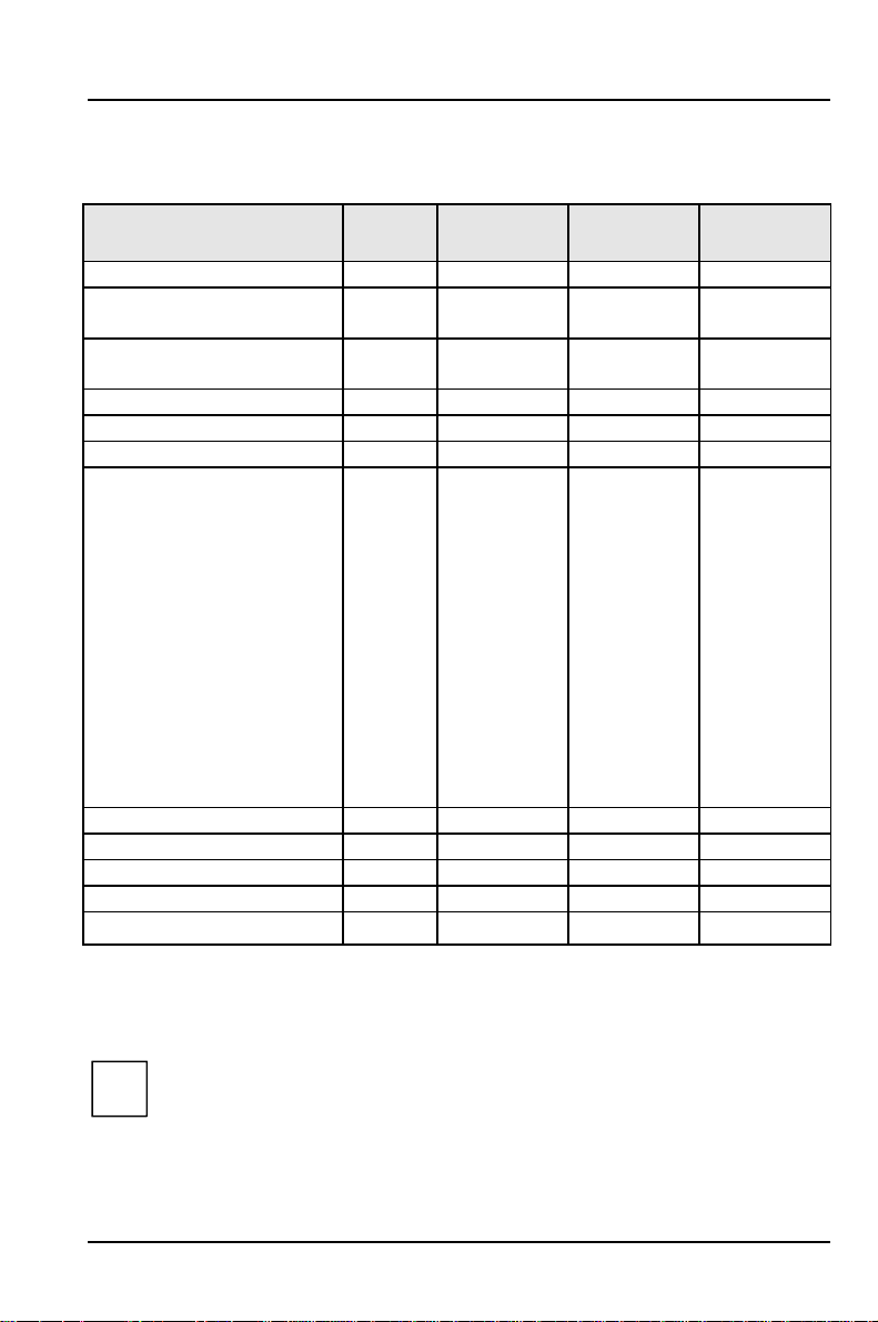
Clock speed - switch 1, 2, 3 and 4
The switches may only be set as specified in the table below for the
!
particular processor used.
processor switch 1 switch 2 switch 3 switch 4
75 MHz on on off off
90 MHz on off off off
100MHz off on off off
120MHz on off on off
133MHz off on on off
150MHz on off on on
166MHz off on on on
200MHz off on off on
233MHz off on off off
Recovering System BIOS - switch 5
Switch 5 enables recovery of the old system BIOS after an attempt to update has
failed. Write protection for the System BIOS must be disabled in the BIOS setup
and before the System BIOS can be recovered (switch 7 = off). To restore the old
BIOS you need a Flash BIOS Diskette (call customer service).
on The System BIOS executes from floppy drive A: and restores the
System BIOS on the system board.
off The System BIOS is started from the system board (default
setting).
48 A26361-D969-Z120-8-7619
Page 57

Settings with switch block S180
Write protection for System BIOS - switch 7
Switch 7 enables and disables system BIOS updating. Before an update of the
system BIOS can be carried out, write protection for the system BIOS must also be
disabled in the BIOS Setup (in the Security menu, the Flash Write field must be set to
Enabled). If you wish to update your system BIOS, please consult our customer
service.
on System BIOS is write protected.
off System BIOS can be overwritten (default setting).
If you change the configuration of your system (for example by installing
!
new add-on boards), you must set switch 7 to off. Only then you can
change the configuration data in the system BIOS.
Write protection for floppy disk drive - switch 8
Switch 8 is used to define whether floppy disks can be written or deleted in the
floppy disk drive. To write and delete floppy disks, the write protection in BIOS setup
must be disabled (in menu Security, the field Diskette Write must be set to Enabled).
on The floppy disk drive is write-protected.
off Read, write and delete floppy disks is possible (default setting).
A26361-D969-Z120-8-7619 49
Page 58

Page 59

Add-on modules
8
9
7
6
5
10
1
2
4
1 = Processor with heat sink
2 = Lithium battery
3 = Flash BIOS
4 = ISA slots (from below: 1, 2, 3)
5 = Socket for video memory
6 = PCI slots (from below: 1, 2, 3, 4)
7 = Location for second-level Cache
8 = Locations bank 1 for main memory
9 = Locations bank 2 for main memory
10 = Heat sink
3
The heat sink can become very hot during operation. Make sure you do
!
not touch components when making extensions to the system board.
There is a danger of burns!
A26361-D969-Z120-8-7619 51
Page 60

Add-on modules Upgrading main memory
Upgrading main memory
Four locations (bank 1 and bank 2) are available on the system board for installing
memory modules. The board supports a maximum of 128 Mbytes.
You may use memory modules of 4, 8, 16 or 32 Mbytes with or without parity
check.
You may only use fast memory modules (access time = 70ns or less) or
!
EDO memory modules (access time = 60ns or less)
In other words, you fit the first pair to bank 1, and the second pair in bank
2. Pairs of memory modules must have the same capacity and the same
access time.
The ECC error identification is only possible for modules with parity
i
checks
Installing memory modules
1
2
Ê Insert the memory module at an angle into the appropriate location (1). Ensure
that the key notch and the two holes are correctly aligned with the retaining
pins.
Ê Tilt the memory module upwards until it snaps into place vertically (2).
52 A26361-D969-Z120-8-7619
Page 61

Upgrading main memory Add-on modules
Removing a memory module
1
3
2
1
Ê Carefully push the retaining clips at each end of the module outwards (1).
Ê Tilt the memory module to the side (2) and withdraw it at an angle from the
location (3).
A26361-D969-Z120-8-7619 53
Page 62

Add-on modules Replacing the processor
Replacing the processor
2
3
1
Ê Push the lever in the direction of the arrow (1) and lift it as far as it will go (2).
Ê Remove the old processor from the socket (3).
Ê Insert the new processor in the socket so that the mark on the upper side of
the processor matches the mark (A) on the socket (4).
The mark on the processor may be covered by a heat sink. In this case let
!
yourself be guided by the marking in the rows of pins on the underside of
the processor.
4
5
A
Ê Push the lever back down so that it snaps into place.
Ê Set the switches 1,2,3and4depending on the processor which is installed.
54 A26361-D969-Z120-8-7619
Page 63

Upgrading the Second-level cache Add-on modules
Upgrading the Second-level cache
The system board has a socket for second-level cache. You can install a
Pipelined-Burst second-level cache module with 128 Kbytes, 256 Kbytes or 512
Kbytes.
To avoid damage to the system board only cache modules released by
!
Siemens should be used.
1
1 = Installing second-level cache 2 = Removing second-level cache
Ê If a second-level cache is already installed, pull it out of the mounting location
in the direction of the arrow (2).
Ê Insert the new second-level cache module into the mounting location, making
sure it snaps into place (1).
To be able to use the second-level cache, you must set the Cache field
i
in the Advanced / Cache Memory menu of the BIOSSetup to Intern and
Extern. You can enhance the performance by setting the Cache System
BIOS Area and Cache Video BIOS Area fields in the same menu to
Enabled and copying ROM sections with Cache memory regions to the
cache.
Removing second-level cache modules
2
Ê Pull the second-level cache module out of the mounting location in the
direction of the arrow.
A26361-D969-Z120-8-7619 55
Page 64

Add-on modules Upgrading the video memory
Upgrading the video memory
If your system board is supplied with a video memory configuration of 1 Mbyte, you
may enlarge the video memory up to 2 Mbytes.
Information on which DRAM components (DRAM 256K*16 16ns) you can
!
use is available from your sales office or the customer service.
Note the location of the DRAM chip when you plug in DRAM chip!
A
Ê Insert the DRAM component in such a way in the socket for video memory that
the mark on the upper side of the DRAM component (A) matches the position
of the mark on the socket.
56 A26361-D969-Z120-8-7619
Page 65

Connecting an audio board Add-on modules
1
2
Game-Port Audio
Connecting an audio board
If an audio board is installed at the front of your system or you install one at the
front, you must attach the connecting line to the Game/Midi / Audio port on the
system board. The Game/Midi / Audio port is a combined plug.
Ê Plug the connecting line onto the side marked with Audio.
If an audio board is installed at the back of your system or you install one at the
back, you must attach the connecting line to the Game/Midi / Audio port on the
system board. The plug on the connecting line is exactly the same width as the
Game/Midi / Audio port.
Ê Plug the connecting line into the Game/Midi / Audio port.
A26361-D969-Z120-8-7619 57
Page 66

Add-on modules Replacing the lithium battery
Replacing the lithium battery
Incorrect replacement of the lithium battery may lead to a risk of
!
explosion.
The lithium battery must be replaced with an identical battery or a battery
type recommended by the manufacturer (CR2032).
Do not throw lithium batteries into the trashcan. It must be disposed of in
accordance with local regulations concerning special waste.
Make sure that you insert the battery the right way round. The plus pole
must be on the top!
1
+
+
Ê Lift the contact (1) a few millimeters and remove the battery from its socket
(2).
Ê Insert a new lithium battery of the same type in the socket (3).
2
+
3
+
58 A26361-D969-Z120-8-7619
Page 67

Error messages
This chapter contains error messages generated by the system board.
Diskette drive A error
Diskette drive B error
Check the entry for the diskette drive in the Main menu of the BIOS Setup.
Check the connections to the diskette drive.
Extended RAM Failed at offset: nnnn
Failing Bits: nnnn
System RAM Failed at offset: nnnn
Switch the PC off and on again. If the message is still displayed, please
contact your sales office or customer service.
Fixed Disk 0 Failure
Fixed Disk 1 Failure
Fixed Disk Controller Failure
Check the entries for the hard disk drive in the Main menu of the BIOSSetup.
Check the hard disk drive's connections and jumpers.
Incorrect Drive A - run Setup
Incorrect Drive B - run Setup
Correct the entry for the diskette drive in the Main menu of the BIOS Setup.
Invalid NVRAM media type
Switch the PC off and on again. If the message is still displayed, please
contact your sales office or customer service.
Invalid System configuration Data
In the Advancedmenu of the BIOS-Setup set the entry for Reset Configuration
Data to Yes.
Keyboard controller error
Connect another keyboard. If the message is still displayed, please contact
your sales office or customer service.
Keyboard error
Check that the keyboard is connected properly.
Keyboard error nn
Release the key on the keyboard (nn is the hexadecimal code for the key).
A26361-D969-Z120-8-7619 59
Page 68

Error messages
Monitor type does not match CMOS - RUN SETUP
Correct the entry for the monitor type in the Main menu of the BIOS Setup.
Operating system not found
Check the entries for the hard disk drive and the floppy disk drive in the Main
menu of the BIOS Setup.
Parity Check 1
Parity Check 2
Switch the PC off and on again. If the message is still displayed, please
contact your sales office or customer service.
Previous boot incomplete - Default configuration used
By pressing function key [F2]
Setup. By pressing function key [F1]
configuration. If the message is still displayed, please contact your sales
office or customer service.
Real time clock failure
Call the BIOS Setup and enter the correct time in the Main menu. If the
message is still displayed, please contact your sales office or customer
service.
System battery is dead - Replace and run SETUP
Replace the lithium battery on the system module and redo the settings in
the BIOS Setup.
System Cache Error - Cache disabled
Switch the PC off and on again. If the message is still displayed, please
contact your sales office or customer service.
System CMOS checksum bad - run SETUP
Call the BIOS Setup and correct the previously made entries or set the default
entries.
System timer error
Switch the PC off and on again. If the message is still displayed, please
contact your sales office or customer service.
[F2] you can check and correct the settings in BIOS
[F2][F2]
[F1] the PC starts with incomplete system
[F1][F1]
60 A26361-D969-Z120-8-7619
Page 69

Messages d'erreur
Messages d'erreur
Ce chapitre vous donne les messages d'erreur générés par le BIOS du système.
Diskette drive A error
Diskette drive B error
Vérifiez dans le menu Main du BIOS setup l'entrée correspondant au lecteur
de disquettes. Vérifiez les connecteurs du lecteur de disquettes.
Extended RAM Failed at offset: nnnn
Failing Bits: nnnn
System RAM Failed at offset: nnnn
Redémarrez votre PC. Si le message réapparaît, adressez-vous à votre
revendeur ou à notre S.A.V.
Fixed Disk 0 Failure
Fixed Disk 1 Failure
Fixed Disk Controller Failure
Vérifiez dans le menu Main du BIOS setup l'entrée correspondant au lecteur
de disque dur. Vérifiez les connecteurs et les cavaliers du lecteur de disque
dur.
Incorrect Drive A - run Setup
Incorrect Drive B - run Setup
Entrez dans le menu Main du BIOS setup et paramétrez correctement
l'entrée correspondant au lecteur de disquettes.
Invalid NVRAM media type
Redémarrez votre PC. Si le message réapparaît, adressez-vous à votre
revendeur ou à notre S.A.V.
Invalid System configuration Data
In the Advancedmenu of the BIOS-Setup set the entry for Reset Configuration
Data to Yes.
Keyboard controller error
Connectez un autre clavier. Si le message réapparaît, adressez-vous à votre
revendeur ou à notre S.A.V.
Keyboard error
Assurez-vous que le clavier est correctement connecté.
A26361-D969-Z120-8-7619 61
Page 70

Messages d'erreur
Keyboard error nn
Libérez la touche du clavier (nn est le code hexadécimal de cette touche).
Monitor type does not match CMOS - RUN SETUP
Entrez dans le menu Main du BIOS setup et paramétrez correctement
l'entrée correspondant au type d'écran.
Operating system not found
Vérifiez dans le menu Main du BIOS setup les entrées correspondant au
lecteur de disque dur et au lecteur de disquettes.
Parity Check 1
Parity Check 2
Redémarrez votre PC. Si le message réapparaît, adressez-vous à votre
revendeur ou à notre S.A.V.
Previous boot incomplete - Default configuration used
Appuyez la touche de fonction [F2]
BIOS Setup. Si vous appuyez la touche de fonction [F1]
configuration incomplète. Si le message réapparaît, adressez-vous à votre
revendeur ou à notre S.A.V.
Real time clock failure
Appelez le BIOS setup et entrez l'heure exacte dans le menu Main. Si le
message réapparaît, adressez-vous à votre revendeur ou à notre S.A.V.
System battery is dead - Replace and run SETUP
Remplacez la batterie au lithium sur la carte système et procédez à de
nouveaux réglages dans le BIOS setup.
System Cache Error - Cache disabled
Redémarrez votre PC. Si le message réapparaît, adressez-vous à votre
revendeur ou à notre S.A.V.
System CMOS checksum bad - run SETUP
Appelez le BIOS setup et corrigez les réglages effectués en dernier lieu ou
activez les réglages standard.
System timer error
Redémarrez votre PC. Si le message réapparaît, adressez-vous à votre
revendeur ou à notre S.A.V.
[F2] pour vérifier et corriger les valeurs dans
[F2][F2]
[F1] le PC démarre en
[F1][F1]
62 A26361-D969-Z120-8-7619
Page 71

Mensajes de error
Mensajes de error
Aquí se describen los mensajes de error que son generados por el BIOS-Setup.
Diskette drive A error
Diskette drive B error
Compruebe en el menú principal del BIOS-Setup el registro para la unidad de
disquete. Compruebe las conexiones de dicha unidad..
Extended RAM Failed at offset: nnnn
Failing Bits: nnnn
System RAM Failed at offset: nnnn
Arranque de nuevo el PC. Si sigue visualizándose este mensaje, diríjase a
su distribuidor o a nuestro servicio de postventa.
Fixed Disk 0 Failure
Fixed Disk 1 Failure
Fixed Disk Controller Failure
Compruebe en el menú principal del BIOS-Setup los registros para la unidad
de disco duro. Compruebe las conexiones y puentes enchufables de la
unidad de disco duro.
Incorrect Drive A - run Setup
Incorrect Drive B - run Setup
Defina correctamente el registro de la unidad de disquete en el menú
principal del BIOS-Setup.
Invalid NVRAM media type
Arranque de nuevo el PC. Si sigue visualizándose este mensaje, diríjase a
su distribuidor o a nuestro servicio de postventa.
Invalid System configuration Data
Pour l'entrée Reset Configuration Data du menu Advanced du BIOS setup,
activez le paramètre Yes.
Keyboard controller error
Conecte otro teclado. Si sigue visualizándose este mensaje, diríjase a su
distribuidor o a nuestro servicio de postventa.
Keyboard error
Compruebe si el teclado está conectado correctamente.
A26361-D969-Z120-8-7619 63
Page 72

Mensajes de error
Keyboard error nn
Desbloquee la tecla del teclado (nn es el código hexadecimal para la tecla).
Monitor type does not match CMOS - RUN SETUP
Defina correctamente en el menú principal del BIOS-Setup el registro para el
tipo de pantalla..
Operating system not found
Compruebe en el menú principal del BIOS-Setup los registros de la unidad de
disco duro y de la unidad de disquete.
Parity Check 1
Parity Check 2
Arranque de nuevo el PC. Si sigue visualizándose este mensaje, diríjase a
su distribuidor o a nuestro servicio de postventa.
Previous boot incomplete - Default configuration used
Pulsando la tecla [F2]
Setup. Pulsando la tecla [F1]
incompleta. Si sigue visualizándose este mensaje, diríjase a su distribuidor o
a nuestro servicio de postventa.
Real time clock failure
Active el BIOS-Setup y registre la hora correcta en el menú principal (Main).
Si sigue visualizándose este mensaje, diríjase a su distribuidor o a nuestro
servicio de postventa..
System battery is dead - Replace and run SETUP
Sustituya la pila de litio en el módulo de sistema y repita las operaciones de
ajuste en el BIOS-Setup..
System Cache Error - Cache disabled
Arranque de nuevo el PC. Si sigue visualizándose este mensaje, diríjase a
su distribuidor o a nuestro servicio de postventa.
System CMOS checksum bad - run SETUP
Active el BIOS-Setup y corrija los últimos registros hechos o ajuste los
registros estándar.
System timer error
Arranque de nuevo el PC. Si sigue visualizándose este mensaje, diríjase a
su distribuidor o a nuestro servicio de postventa.
[F2] puede verificar y corregir los registros del BIOS-
[F2][F2]
[F1] , el sistema arranca con la configuración
[F1][F1]
64 A26361-D969-Z120-8-7619
Page 73

Messagi di errore
Messagi di errore
I messaggi di errore emessi dal system BIOS sono descritti qui in seguito.
Diskette drive A error
Diskette drive B error
Controllate il valore indicato per il drive per dischetti nel BIOS-Setup del menu
principale (Main). Controllate i collegamenti del drive per dischetti.
Extended RAM Failed at offset: nnnn
Failing Bits: nnnn
System RAM Failed at offset: nnnn
Riavviate nuovamente il PC. Se il messaggio ricompare rivolgeteVi al Vostro
rivenditore o al nostro servizio di assistenza tecnica..
Fixed Disk 0 Failure
Fixed Disk 1 Failure
Fixed Disk Controller Failure
Controllate nel BIOS-Setup del menu principale i valori indicati per il drive del
disco rigido. Controllate i collegamenti ed i ponticelli del drive del disco
rigido.
Incorrect Drive A - run Setup
Incorrect Drive B - run Setup
Impostate nel BIOS-Setup del menu principale (Main) il valore corretto per il
drive per dischetti.
Invalid NVRAM media type
Riavviate nuovamente il PC. Se il messaggio ricompare rivolgeteVi al Vostro
rivenditore o al nostro servizio di assistenza tecnica.
Invalid System configuration Data
En el menú Advanceddel BIOS-Setup ajuste el valor Yes para Reset
Configuration Data.
Keyboard controller error
Collegate un'altra tastiera. Se il messaggio ricompare rivolgeteVi al Vostro
rivenditore o al nostro servizio di assistenza tecnica.
Keyboard error
Controllate che la tastiera sia collegata correttamente.
A26361-D969-Z120-8-7619 65
Page 74

Messagi di errore
Keyboard error nn
Liberate il tasto dalla tastiera (nn indica il codice esadecimale del tasto).
Monitor type does not match CMOS - RUN SETUP
Impostate nel BIOS-Setup del menu principale (Main) il valore corretto per il
tipo di monitor.
Operating system not found
Controllate nel BIOS-Setup del menu principale i valori indicati per il drive
per il disco rigido e per il drive per dischetti.
Parity Check 1
Parity Check 2
Riavviate nuovamente il PC. Se il messaggio ricompare rivolgeteVi al Vostro
rivenditore o al nostro servizio di assistenza tecnica.
Previous boot incomplete - Default configuration used
Premendo il tasto funzione [F2]
nel BIOS-Setup. Premendo il tasto funzione [F1]
cofigurazione di sistema completa. Se il messaggio ricompare rivolgeteVi al
Vostro rivenditore o al nostro servizio di assistenza tecnica.
Real time clock failure
Richiamate il BIOS-Setup ed inserite nel menu principale (Main) l'ora esatta.
Se il messaggio ricompare rivolgeteVi al Vostro rivenditore o al nostro
servizio di assistenza tecnica.
System battery is dead - Replace and run SETUP
Sostituite la batteria al litio dell'unità di sistema ed inserite nuovamente i
valori di impostazione nel BIOS-Setup.
System Cache Error - Cache disabled
Riavviate nuovamente il PC. Se il messaggio ricompare rivolgeteVi al Vostro
rivenditore o al nostro servizio di assistenza tecnica..
System CMOS checksum bad - run SETUP
Richiamate il BIOS-Setup e correggete gli ultimi valori impostati oppure
indicati i valori standard.
System timer error
Riavviate nuovamente il PC. Se il messaggio ricompare rivolgeteVi al Vostro
rivenditore o al nostro servizio di assistenza tecnica.
[F2] potete verificare e corregere le impostazioni
[F2][F2]
[F1] , il PC viene avviato con la
[F1][F1]
66 A26361-D969-Z120-8-7619
Page 75

Felmeddelanden
Felmeddelanden
Nedan beskrivs de felmeddelanden som system-BIOS matar ut på
systemkomponenten.
Diskette drive A error
Diskette drive B error
Kontrollera inställningen för diskettenheten i menyn Main i BIOS-Setupmenyn. Kontrollera diskettenhetens anslutningar.
Extended RAM Failed at offset: nnnn
Failing Bits: nnnn
System RAM Failed at offset: nnnn
Starta upp PCn på nytt. Om meddelandet fortfarande visas bör du kontakta
din återförsäljare eller vår kundservice.
Fixed Disk 0 Failure
Fixed Disk 1 Failure
Fixed Disk Controller Failure
Kontrollera inställningarna förhårddisken i menyn Main i BIOS-Setup-menyn.
Kontrollera hårddiskens anslutningar och insticksbryggorna.
Incorrect Drive A - run Setup
Incorrect Drive B - run Setup
Korrigera inställningen för diskettenheten i menyn Main i BIOS-Setup-menyn.
Invalid NVRAM media type
Starta upp PCn på nytt. Om meddelandet fortfarande visas bör du kontakta
din återförsäljare eller vår kundservice.
Invalid System configuration Data
Ställ in värdet Yes för Reset Configuration Data i menyn Advanced i BIOS-Setupmenyn.
Keyboard controller error
Anslut ett annat tangentbord. Om meddelandet fortfarande visas bördu
kontakta din återförsäljare eller vår kundservice.
Keyboard error
Kontrolla att tangentbordet är korrekt anslutet.
Keyboard error nn
Frigör den angivna tangenten (nn är tangentens hexadecimalkod).
A26361-D969-Z120-8-7619 67
Page 76

Felmeddelanden
Monitor type does not match CMOS - RUN SETUP
Korrigera inställningarna för bildskärmtypen i menyn Main i BIOS-Setup
menyn.
Operating system not found
Kontrollera inställningarna förhårddisken och diskettenheten i menyn Main i
BIOS-Setup-menyn.
Parity Check 1
Parity Check 2
Starta upp PCn på nytt. Om meddelandet fortfarande visas bör du kontakta
din återförsäljare eller vår kundservice.
Previous boot incomplete - Default configuration used
Om du trycker på funktionstangenten [F2]
inställningarna i BIOS-Setup. Om du trycker på funktionstangenten [F1]
startas PCn med den ofullständige systemkonfigurationen. Om meddelandet
fortfarande visas bör du kontakta din återförsäljare eller vår kundservice.
Real time clock failure
Ropa upp BIOS-Setup-menyn och ställ in korrekt klockslag i menyn Main.Om
meddelandet fortfarande visas bör du kontakta din återförsäljare eller vår
kundservice.
System battery is dead - Replace and run SETUP
Byt ut litiumbatteriet på systemkomponenten och genomför inställningarna i
BIOS-Setup-menyn på nytt.
[F2] , kan du kontrollera och korrigera
[F2][F2]
[F1]
[F1][F1]
System Cache Error - Cache disabled
Starta upp PCn på nytt. Om meddelandet fortfarande visas bör du kontakta
din återförsäljare eller vår kundservice.
System CMOS checksum bad - run SETUP
Ropa upp BIOS-Setup-menyn. Korrigera de senast gjorda inställningarna eller
ställ in standardvärdena igen.
System timer error
Starta upp PCn på nytt. Om meddelandet fortfarande visas bör du kontakta
din återförsäljare eller vår kundservice.
68 A26361-D969-Z120-8-7619
Page 77

Foutmeldingen
Foutmeldingen
Vervolgens worden de foutmeldingen beschreven die het BIOS-systeem op de
systeembouwgroep geeft.
Diskette drive A error
Diskette drive B error
Controleer in de setup van het BIOS, in het menu Main, de instelling van het
diskettestation. Controleer de aansluitingen van het diskettestation.
Extended RAM Failed at offset: nnnn
Failing Bits: nnnn
System RAM Failed at offset: nnnn
Start de PC opnieuw. Als de melding opnieuw verschijnt, neem dan a.u.b.
contact op met uw dealer of met onze klantendienst.
Fixed Disk 0 Failure
Fixed Disk 1 Failure
Fixed Disk Controller Failure
Controleer in de setup van het BIOS, in het menu Main, de instellingen van
de harde schijf. Controleer de aansluitingen en de jumpers van de harde
schijf.
Incorrect Drive A - run Setup
Incorrect Drive B - run Setup
Stel in de setup van het BIOS, in het menu Main,het diskettestation op de
juiste wijze in.
Invalid NVRAM media type
Start de PC opnieuw. Als de melding opnieuw verschijnt, neem dan a.u.b.
contact op met uw dealer of met onze klantendienst.
Invalid System configuration Data
Zet in de BIOS-Setup in het menu Advanced de instelling voor Reset
Configuration Data op Yes.
Keyboard controller error
Sluit een ander toetsenbord aan. Als de melding opnieuw verschijnt, neem
dan contact op met uw dealer of met onze klantendienst.
Keyboard error
Controleer of het toetsenbord goed is aangesloten.
A26361-D969-Z120-8-7619 69
Page 78

Foutmeldingen
Keyboard error nn
Laat de toets van het toetsenbord los (nn is de hexadecimale code voor de
toets).
Monitor type does not match CMOS - RUN SETUP
Stel in de setup van het BIOS, in het menu Main,het monitortype op de juiste
wijze in.
Operating system not found
Controleer in de setup van het BIOS, in het menu Main, de instellingen van
de harde schijf en het diskettestation..
Parity Check 1
Parity Check 2
Start de PC opnieuw. Als de melding opnieuw verschijnt, neem dan a.u.b.
contact op met uw dealer of met onze klantendienst.
Previous boot incomplete - Default configuration used
Als u op de functietoets [F2]
instelling uittesten en verbeteren. Als u op de functietoets [F1]
PC met de onvolledige systeemconfiguratie. Als de melding opnieuw
verschijnt, neem dan a.u.b. contact op met uw dealer of met onze
klantendienst.
Real time clock failure
Roep de setup van het BIOS op en stel in het menu Main de juiste tijd in.Als
de melding opnieuw verschijnt, neem dan a.u.b. contact op met uw dealer of
met onze klantendienst.
[F2] drukt, kunt u in de setup van het BIOS de
[F2][F2]
[F1] drukt, start de
[F1][F1]
System battery is dead - Replace and run SETUP
Vervang de lithiumbatterij op het motherboard en stel de BIOS opnieuw in.
System Cache Error - Cache disabled
Start de PC opnieuw. Als de melding opnieuw verschijnt, neem dan a.u.b.
contact op met uw dealer of met onze klantendienst.
System CMOS checksum bad - run SETUP
Roep de setup van het BIOS op en corrigeer wat u voor het laatst heeft
ingesteld of stel de defaultwaarden in.
System timer error
Start de PC opnieuw. Als de melding opnieuw verschijnt, neem dan a.u.b.
contact op met uw dealer of met onze klantendienst.
70 A26361-D969-Z120-8-7619
Page 79

Index
3
32 Bit I/O 16
5
528 Mbyte, Festplattenkapazität 15
A
Abspeichern, siehe Speichern
Adresse 7
Serielle Schnittstelle 24
Adressierung, Festplatte 15
Advanced BIOS-Setup 19
Advanced Power Management, siehe APM-Schnittstelle
Advanced System Configuration 29
Akkumulator 58
Aktuellen Systemzustand, speichern 41
Anschließen, Audiobaugruppe 57
Anschluß 4
Game/Midi / Audio 57
Anzahl
Faxton 45
Klingeln 44
APM-Schnittstelle 39
Arbeitsspeicher 52
Größe 18
ASR&R Boot Delay 38
Audio Controller 3, 26
Audiobaugruppe, anschließen 57
Audioeingang 3
Ausbauen
Second-Level-Cache 55
Speichermodul 53
Ausschalten
Audio-Controller 26
Feature Connector 30
Maus-Controller 26
Plug&Play 31
USB-Controller 26
Auswirkung
A26361-D969-Z120-8-7619 71
Page 80

Index
Setup-Paßwort 33
System-Paßwort 34
Autotype Hard Disk 14
AUX-in, Steckverbinder 3
B
Base Memory 18
Batterie
Austausch 58
Entsorgung 58
Baugruppe 4
Sicherheitshinweise 10
Beenden, BIOS-Setup 46
Belegung
DMA 7
Interrupt 7
Betriebssystem
ausschalten 36
starten 34
Bidirection 25
Bildschirmauflösungen 5
Bildschirmtyp 18
Bildwiederholspeicher, hochrüsten 56
BIOSFaX 44
BIOS-Setup
beenden 46
Einstellungen 11
Energiesparfunktionen 39
erweiterte Systemeinstellungen 19
Menü Advanced 19
Menü BIOSFaX 44
Menü Exit 46
Menü Main 11
Menü Power 39
Menü Security 32
Sicherheitsfunktionen 32
Systemkonfiguration 11
BIOS-Update 48, 49
Diskette 35
Boot Options 16
Boot Sequence 18
Boot-Logo 17
Boot-Optionen 16
72 A26361-D969-Z120-8-7619
Page 81

Bootreihenfolge 18
Bootsektor, Veränderungen 35
Busbreite einstellen 16
C
Cache
BIOS 21
Cache-Funktion 21
Cache-Nutzung 20
einstellen 55
ROM-Bereiche 21
Schreibzugriff 21
Second-Level-Cache hochrüsten 55
Cache Memory 20
Cache Memory Regions 21
Cache Mode 21
Cache System BIOS Area 21
Cache Video BIOS Area 21
CD-Line in, Steckverbinder 3
Chipcard 38
Chipkartenleser 38
Computerviren 35
Controller
Audio 26
Diskettenlaufwerk 25
Laufwerk 25
Maus 26
USB 26
Cylinders, Festplattenparameter 15
Index
D
Darstellungsmittel 1
Daten, Technische 2
Datenübertragung
Modus einstellen 25
Parallele 25
Datum einstellen 12
Default Latency Timer 29
DeskOff 36
Discard Changes & Exit 46
DisketteA/B 12
Diskette Controller 25
Diskette Lock 34
A26361-D969-Z120-8-7619 73
Page 82

Index
Diskette Write 35, 49
Diskettenlaufwerk
Schreibschutz 35, 49
Typ 12
Diskettenlaufwerks-Controller 25
einstellen 25
DMA 7
DRAM-Baustein 56
DRAM-Modul 56
DRAM-Paritätsprüfung 30
E
ECC 30, 52
Echtzeituhr-Baustein 58
ECP 25
EGB 10
Ein-/Ausschalten
System 36
Ursachen 36
Ein-/Ausschalt-Funktionalität 36
Ein-/Aus-Taster 36
Einbauen
Second-Level-Cache 55
Speichermodul 52
Einschalten
Audio-Controller 26
Chipkartenleser 38
Feature Connector 30
Maus-Controller 26
Plug&Play 31
USB-Controller 26
Einschaltzeit 38
Einstellungen
BIOS-Setup 11
Power-Management 39
speichern 46
Energie, sparen 40
Energiesparfunktionen
BIOS-Setup 39
einstellen 39
Festplattenlaufwerk 41
Umfang 40
Energiesparmodus 43
74 A26361-D969-Z120-8-7619
Page 83

Enhanced Capability Port, siehe ECP
Enhanced Parallel Port, siehe EPP
EPP 25
Erhöhen, Performance 16
Erreur, messages 61
Error Correction Code, siehe ECC
Error messages 59
Error, mensajes 63
Errore, messagi 65
Erweiterte Systemeinstellungen 19
Erweiterungsspeicher, Größe 18
Exit, BIOS-Setup 46
Extended Memory 18
Externer Cache
einstellen 20
Second-Level-Cache 20
F
F1 11
F2 34
Fax Modem Port 45
Fax Tone Count 45
Feature Connector 30
Fehlererkennung 52
Felmeddelanden 67
Fernein-Funktionalität 37
Ferneinschalten 37
Festplatte
Adressierung 15
Festplattenkapazität 15
Parameter 14
Übertragungsgeschwindigkeit 16
Übertragungsmodus 15
Festplattenkapazität 15
Festplattenlaufwerk 13
Controller 25
Energiesparfunktionen 41
Festplattenparameter 14
Festplattenparameter
Cylinders 15
Heads 15
Sectors/Track 15
Write Precomp 15
Index
A26361-D969-Z120-8-7619 75
Page 84

Index
Festplattentyp 14
Festplattenzugriff 31
First-Level-Cache
einstellen 20
interner Cache 20
Flash Write 35
Flash-BIOS, Schreibschutz 35
Flash-BIOS-Diskette 48
Foutmeldingen 69
Freischalten, Feature Connector 30
Funktionalität, ein-/ausschalten 36
Funktionstaste
F1 11
F2 34
G
Game/Midi / Audio 3, 57
Game/Midi, Steckverbinder 3
Get Default Values 46
Grafik-Controller 3
Bildschirmauflösungen 5
H
HAL 36
Hard Disk 13
Hard Disk Controller 25
Hard Disk Timeout 41
Hardware Abstraction Layer, siehe HAL
Hauptspeicher 52
hochrüsten 52
vergrößern 52
Heads, Festplattenparameter 15
Hilfetext aufrufen 11
Hochlaufroutine 16, 17, 18
Hochrüsten
Hauptspeicher 52
Second-Level-Cache 55
I
IDE-Festplatte, siehe Festplatte
IDE-Festplattenlaufwerk, siehe Festplattenlaufwerk
Infrarotschnittstelle 24
Initialisieren, Konfigurierungsdaten 31
76 A26361-D969-Z120-8-7619
Page 85

Installation
Setup-Paßwort 33
System-Paßwort 33
Interner Cache
einstellen 20
First-Level-Cache 20
Schreibzugriff 21
Interrupt 7
Serielle Schnittstelle 24
zuordnen 28
Interrupt-Tabelle 7
ISA Memory Gap 30
ISA-Speicherbereich 30
K
Keyboard
System ausschalten 37
System einschalten 37
System-Paßwort 34
Konfiguration, BIOS-Setup 11
Konfigurierungsdaten, initialisieren 31
Kopfhöreranschluß 3
Kurzer Selbsttest 17
Index
L
Lage, Schalterblock 47
Large Disk Access Mode 31
Latency Timer 29
Laufwerks-Controller 25
ausschalten 25
einstellen 23
LBA Translation 15
Leistungsmerkmale 2
Lithium-Batterie 58
Load Previous Values 46
Logical Block Addressing, siehe LBA
M
Main, Menü 11
Mensajes de error 63
Menü
Advanced 19
BIOSFaX 44
A26361-D969-Z120-8-7619 77
Page 86

Index
BIOS-Setup 11
Exit 46
Main 11
Power 39
Security 32
Menü Security, Flash Write 49
Messages 59
Messages d'erreur 61
Messagi di errore 65
Mikrofonanschluß 3
Modem Modus 44
Modem, einstellen 44
Mouse Controller 26
P
Parallel
Datenübertragung 25
Schnittstelle 24, 25
Parallel Mode 25
Parameter, Festplatte 14
Paritätsprüfung 30, 52
Parity Mode 30
Paßwort
Setup-Paßwort 33
System-Paßwort 33, 34
Paßwortanzeige 32
PCI 1
PCI Configuration 27
PCI Device, Slot #n 29
PCI Interrupt Mapping INTx# 28
PCI-Einstellungen 27
PCI-Funktionalität 27
PCI-Interrupt, zuordnen 28
PCI-Steckplatz
Default Latency Timer 29
einstellen 29
Latency Timer 29
PCI-VGA-Interrupt, zuordnen 28
Performance, erhöhen 16, 20, 21, 22, 23, 30, 55
Peripheral Component Interconnect, siehe PCI
Peripheral Configuration 23
Peripherie 23
PIO Mode 16
78 A26361-D969-Z120-8-7619
Page 87

Plug & Play O/S 31
Plug&Play, Funktionalität 31
POST Error Halt 17
Power Management Mode 40
Power Off Source
Keyboard 37
Software 36
Power On Source
Keyboard 37
Remote 37
Timer 38
Power On/Off 36
Power, BIOS-Setup 39
Power-Management, Einstellungen 39
Press F2 to enter SETUP 34
Primärer Steckverbinder, Laufwerks-Controller 25
Printer 25
Programm, System ausschalten 36
Programmed Input Output Mode, siehe PIO
Prozessor
austauschen 54
interner Cache 20
Taktfrequenz 48
Prozessortakt, Standby-Funktion 41
Index
Q
Quick boot 17
Quiet boot 17
R
RAM 22
Random Access Memory, siehe RAM
Read Only Memory, siehe ROM
Receive Mode 44
Modem Modus 44
Recycling, Batterie 58
Reihenfolge, Systemstart 18
Remote Power On 37
Reset Configuration Data 31
Ressourcen-Tabelle 7
Ring Count 44
ROM 22
ROM-Bereiche 23
A26361-D969-Z120-8-7619 79
Page 88

Index
kopieren 22
S
S180, Schalterblock 47
Save Changes 46
Save Changes & Exit 46
Save To Disk 41
SAVETO.DSK 41
Schalter 1, 2, 3 und 4
Taktfrequenz 54
Schalter 1, 2, 3 und 4, Taktfrequenz 48
Schalter 5, System-BIOS wiederherstellen 48
Schalter 7, Schreibschutz System-BIOS 48, 49
Schalter 8, Schreibschutz Diskettenlaufwerk 49
Schalterblock, Lage 47
Schnittstelle 4
einstellen 23, 24, 25
parallel 24
seriell 24, 45
Schreibschutz
Diskettenlaufwerk 35, 49
System-BIOS 35, 49
Second-Level-Cache
ausbauen 55
einstellen 20
externer Cache 20
hochrüsten 55
Schreibzugriff 21
Sectors/Track, Festplattenparameter 15
Security, BIOS-Setup 32
Sekundärer Steckverbinder, Laufwerks-Controller 25
Selbsttest 16, 17
Serial 1
Adresse 24
ausschalten 24
Interrupt 24
Serial 2
Adresse 24
ausschalten 24
Interrupt 24
Serial 2 Mode 24
Serielle Schnittstelle 45
einstellen 24
80 A26361-D969-Z120-8-7619
Page 89

Set Setup Password 33
Set System Password 33, 36, 37, 38
Setup Password 32
Setup Password Lock 33
Setup Prompt 34
Setup, siehe BIOS-Setup
Setup-Aufforderung 34
Setup-Paßwort
Auswirkung 33
Installation 33
Shadow Memory 22
Shadow Memory Regions 23
Sicherheitsfunktionen, BIOS-Setup 32
Sicherheitshinweise, Baugruppe 10
Software, System ausschalten 36
Speicher
Arbeitsspeicher 18
Bildwiederholspeicher 56
Cache 20
Erweiterungsspeicher 18
Hauptspeicher 18, 52
Second-Level-Cache 55
Speicherausbau, Hauptspeicher 52
Speicherbereich, ISA-Baugruppe 30
Speicherkapazität, Festplatte 15
Speichermodul 52
ausbauen 53
einbauen 52
Speichern
Aktuellen Systemzustand 41
Einstellungen 46
Standby CPU Speed 41
Standby Timeout 40
Standby-Funktion, Taktfrequenz 41
Standby-Modus 40
Startreihenfolge 18
Steckplätze 4
Steckverbinder 4
AUX-in 3
CD-Line in 3
Game/Midi 3
Voice-Modem 3
Suspend Timeout 40
Index
A26361-D969-Z120-8-7619 81
Page 90

Index
Suspend-Modus 40
SWOFF 36
System
anhalten 17
Ein-/Ausschalten 36
System ausschalten
Keyboard 37
Software 36
System Date 12
System einschalten
Fernein 37
Keyboard 37
Tastatur 37
Zeitgesteuert 38
System Load 34
System Password 32
System Password Mode 34, 36, 37, 38
System Performance 30
System Shadow 22
System Time 12
Systemaktivitäten, festlegen 43
Systembaugruppe, siehe Baugruppe
System-BIOS
Schreibschutz 35, 49
wiederherstellen 48
Systemeinstellungen
Erweitert 19
vornehmen 11
zusätzliche 29
Systemgeschwindigkeit 30
Systemkonfiguration, BIOS-Setup 11
System-Paßwort
Auswirkung 34
Installation 33
Systemstart 16, 17, 18
System-Timing 30
Systemzustand 41
T
Taktfrequenz
Schalter 48
Standby-Funktion 41
Taktzyklus, PCI-Steckplatz 29
82 A26361-D969-Z120-8-7619
Page 91

Tastatur
System ausschalten 37
System einschalten 37
Technische
Daten 2
Informationen 11
Testroutine 16, 17
Transfer Mode 15
Type, Festplattentyp 14
Ü
Übertragungsgeschwindigkeit, Festplatte 16
Übertragungsmodus 21
Festplatte 15
parallele Schnittstelle 25
U
Uhrzeit einstellen 12
Umfang, Energiesparfunktionen 40
Unterstützte Bildschirmauflösungen 5
Update
BIOS 48
fehlerhaft 48
USB Controller 26
Index
V
Veränderungen, Bootsektor 35
Verfügbarer
Arbeitsspeicher 18
Erweiterungsspeicher 18
Verkürzter Selbsttest 17
VGA Interrupt 28
Video Display 18
Video Shadow 22
Video-BIOS 22
Virus Warning 35
Viruswarnung 35
Voice-Modem, Steckverbinder 3
W
Wakeup Event 43
Wavetable-Baugruppe 3
Wiederherstellen, System-BIOS 48
A26361-D969-Z120-8-7619 83
Page 92

Index
Write Back 21
Write Precomp, Festplattenparameter 15
Write Through 21
Z
Zeit einstellen 12
Zeitgesteuert, einschalten 38
Zuordnen
PCI-Interrupt 28
PCI-VGA-Interrupt 28
Zusätzlich, Systemeinstellungen 29
84 A26361-D969-Z120-8-7619
 Loading...