

Fujitsu siemens D943 DATASHEET

System board D943
Technical Manual

Is there ...
q
p
y
y
t
g
p
p
y
g
y
p
g
... anytechnicalproblem or other
uestionyou need clarified?
Please contact:
• oneofourITServiceSho
•
our salespartner
•
our sales outle
The addresses of our IT Service Shops
can be found in the
booklet.
The latest information on our
ti
s, updates, etc., can be found on the
Internet under:
http://www.siemensnixdorf.com/pc
uarantee coupon
s
roducts,
... anythingyou want to tell us
about this manual?
Please send us
the order number of the manual.
Siemens Nixdorf Informationss
AG
User Documentation De
OEC BS2 OS ID 4 Otto-Hahn-Rin
D-81730 München
our commentsquotin
steme
artment,
6


Dieses Handbuch wurde auf Recycling-Papier gedruckt.
This manual has been printed on recycled paper.
Ce manuel est imprimé sur du papier recyclé.
Este manual ha sido impreso sobre papel reciclado.
Questo manuale è stato stampato su carta da riciclaggio.
Denna handbok är tryckt på recyclingpapper.
Dit handboek werd op recycling-papier gedrukt.
Herausgegeben von/Published by
Siemens Nixdorf Informationssysteme AG
D-33094 Paderborn
D-81730 München
Bestell-Nr./Order No.: A26361-D943-Z120-14-7619
Printed in the Federal Republic of Germany
AG 0298 02/98
A26361-D943-Z120-14-7619
A26361-D943-Z120-14-7619A26361-D943-Z120-14-7619
A26361-D943-Z120-1-7619

Introduction
p
k
Important notes
System board D943
Technical Manual
SettingsinBIOSSetu
Settings with switch bloc
S180
Add-on modules
Error messages
Index
February 1998 edition

Your training needs?
The Siemens Nixdorf Training Centers offer you a wide range of training courses
in information technology and on IT products and other subjects - onsite near to
your workplace or offsite at one of our training centers.
Contact us for information on consulting, course schedules and selfstudy material Either fax (which is the fastest way):
Fax: ..49 89 636-42945
Or write to:
Siemens Nixdorf Informationssysteme AG
Training Center, Beratungsservice
D-81730 München
Creative is a registered trademark, Sound Blaster 16 and VIBRA 16C are trademarks of Creative
Technology Ltd.
Intel,Pentiumand Pentium Pro are registered trademarks and OverDrive is a trademark of Intel
Corporation, USA.
AMD-K5 is a trademark of Advanced Micro Devices, Inc.
Microsoft, MS, MS-DOS and Windows are registered trademarks of Microsoft Corporation.
PS/2 and OS/2 Warp are registeredtrademarks of International Business Machines, Inc.
All other trademarks referenced are trademarks or registered trademarks of their respective owners,
whose protected rights are acknowledged.
Copyright ã SiemensNixdorf Informationssysteme AG 1998.
All rights, includingrightsoftranslation, reproduction by printing, copying or similar methods, even
of parts are reserved.
Offenders will be liable for damages. All rights, including rights created by patent grant or registration
of a utility model or design, are reserved. Delivery subject to availability. Right of technical
modification reserved.

Contents
Introduction........................................................................................................... 1
Notational conventions............................................................................................ 1
Features................................................................................................................... 2
Interfaces and connectors........................................................................................ 4
Possible screen resolution ....................................................................................... 5
Resource table.........................................................................................................7
Important notes..................................................................................................... 9
Settings in BIOS Setup ....................................................................................... 11
Main menu ............................................................................................................ 11
System Time / System Date ........................................................................... 12
Diskette A / Diskette B .................................................................................. 12
HardDisk1toHardDisk4-Harddiskdrives.............................................. 13
Boot Options.................................................................................................. 16
Video Display ................................................................................................ 18
Base Memory................................................................................................. 18
Extended Memory.......................................................................................... 18
Advanced menu - Making advanced system settings ............................................ 19
Cache Memory............................................................................................... 20
Shadow Memory............................................................................................ 22
Peripheral Configuration - Ports and Controllers........................................... 23
PCI Configuration.......................................................................................... 27
Advanced System Configuration.................................................................... 29
Plug & Play O/S............................................................................................. 31
Reset Configuration Data............................................................................... 32
Large Disk Access Mode - Hard d isk access ................................................. 32
Menu Security - Setting up the security features...................................................33
Setup Password / System Password ............................................................... 33
Set Setup Password........................................................................................ 34
SetupPasswordLock..................................................................................... 34
Set System Password...................................................................................... 34
System Password Mode ................................................................................. 35
System Load................................................................................................... 35
Setup Prompt- Setup message........................................................................ 35
Virus Warning................................................................................................ 36
Diskette Write................................................................................................ 36
Flash Write..................................................................................................... 36
A26361-D943-Z120-14-7619

Contents
Power On/Off.................................................................................................37
Power menu - Setting energy saving functions......................................................40
APM - Enabling the APM Interface...............................................................40
Power Management Mode - Extent of energy saving functions .....................41
Standby Timeout............................................................................................41
Suspend Timeout - Suspend mode .................................................................41
Hard Disk Timeout.........................................................................................42
Standby CPU Speed .......................................................................................42
Save To Disk..................................................................................................42
Wakeup Event - Defining system activities....................................................44
BIOSFaX menu - quick start functions..................................................................45
Receive Mode.................................................................................................45
Ring Count .....................................................................................................45
Fax Tone Count..............................................................................................46
Fax Modem Port - Serial port.........................................................................46
Exit menu ..............................................................................................................47
Save Changes & Exit......................................................................................47
Discard Changes & Exit.................................................................................47
Get Default Values.........................................................................................47
Load Previous Values .....................................................................................47
Save Changes .................................................................................................47
Settings with switch block S180..........................................................................49
Clock speed - switch 1, 2, 3 and 4.........................................................................49
Write protection for System BIOS - switch 5........................................................50
Recovering System BIOS - switch 7......................................................................50
Write protection for floppy disk drive - switch 8 ..................................................50
Add-on modules...................................................................................................51
Upgrading main memory.......................................................................................51
Installing memory modules ............................................................................52
Removinga memory module..........................................................................52
Replacing the processor.........................................................................................53
Upgrading the second-level cache .........................................................................54
Upgrading the video memory ................................................................................54
Connecting an audio board....................................................................................56
Replacing the lithium battery.................................................................................57
Error messages.....................................................................................................59
Index.....................................................................................................................61
A26361-D943-Z120-14-7619
Introduction
p
t
y
g
g
y
This description applies for the System board D943 with PCI bus (Peripheral
Component Interconnect).
This system board is available in different configuration levels.
i
De
endingon the hardware configuration ofyour device, it maybe tha
ou cannot find several options inyour version of the system board, even
thou
htheyare d escribed.
Further information to drivers is provided in the readme files on hard disk or on
the supplied drivers diskettes or on the "Drivers & Utility" CD.
Notational conventions
The meanings of the symbols and fonts used in this manual are as follows:
Payparticular attention to texts marked with this symbol. Failure to
observe this warnin
!
lead to loss of data.
This symbol is followed by supplementary information, remarks and tips.
i
Ê Texts which follow this symbol describe activities that must be performed in
the order shown.
Ë This symbol means that you must enter a blank space at this point.
ÚÚÚÚ
This symbol means that you must press the Enter key.
Texts in this typeface are screen outputs from the PC.
Texts in this bold typeface are the entries you make via the keyboard.
Texts in italics indicate commands or menu item.
"Quotation marks" indicate names of chapters and terms that are being
emphasized.
endangersyour life, destroysthesystem, or ma
A26361-D943-Z120-14-7619 1

Introduction Features
Features
• 64-bit microprocessor Intel Pentium with 16 Kbytes internal cache (first-level
cache, 8 Kbytes data cache, 8 Kbytes address cache) or OverDrive-Processor
for Pentium
or
• AMD-K5
• Memory configuration on the system board: 8 to 128 Mbyte (FPM or EDO)
• Error recognition via ECC
• Second-level cache on the system board: 0, 256 or 512 Kbytes (PBSRAM)
• 256 Kbytes Flash BIOS
• PCI bus
• IDE hard disk controller connected to PCI bus for up to four IDE drives
(e.g. IDE hard disk drives, ATAPI CD ROM drive)
• Real-time clock/calendar with integrated battery backup
• Floppy disk controller (up to 2.88 Mbytes format)
• Bus interface for platter
• Connector for feature connector, loudspeaker
• Parallel interface (ECP- and EPP-compatible)
• 2 serial ports
• PS/2 mouse port
• PS/2 keyboard port
• Security functions
2 A26361-D943-Z120-14-7619

Features Introduction
Optional Components
• Monitor port
• Graphics controller connected to PCI bus, graphics processor Cirrus Logic
CL-GD5436 with Windows accelerator and 1 Mbyte or 2 Mbytes DRAM
video memory
• Audio controller on ISA-BUS (Creative VIBRA 16S; 16 bit; compatible with
Sound Blaster 16, MPU401, Multimedia PC and Multimedia PC II; StereoFM synthesizer YAMAHA OPL3)
• USB (Universal Serial Bus)
• Energy saving functions
• Connector for remote-on (fax/modem board), chipcard reader and infrared
interface
• Connector for CD-line in, wavetable module, Game/Midi, voice modem,
AUX-in
• Microphone connector (via supplementary board)
• Audio port (line in) (via supplementary board)
• Headphone connector (via supplementary board)
The microphone connector, audio port and headphone connector are
i
connected via a common plug (Game/Midi / Audio) on the system board.
A26361-D943-Z120-14-7619 3
Introduction Interfaces and connectors
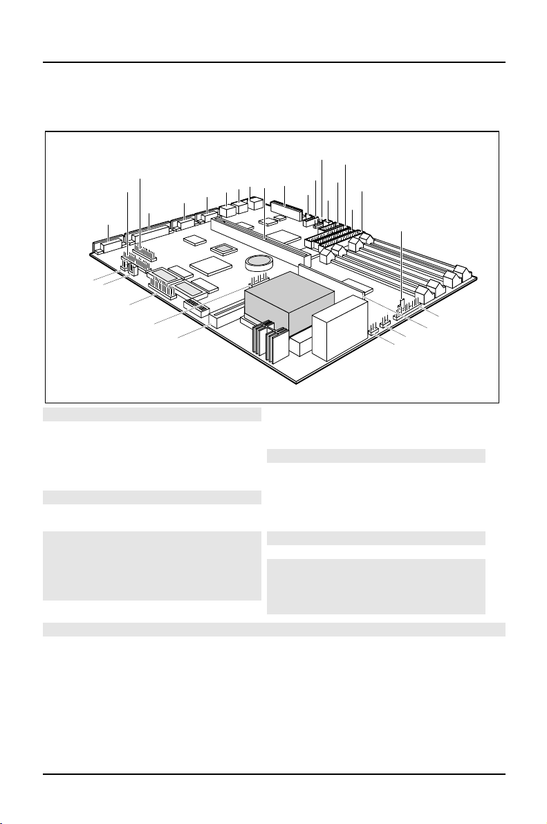
Interfaces and connectors
12
10
11
13
14
15
16
17
18
22
21
19
20
27
26
29
28
1
25
3
2
24
23
6
5
4
9
7
8
1 = Monitor port
2 = Parallel port
3 = Serial port 2
4 = Serial port 1
5= PS/2mouseport
6= PS/2keyboardport
7= USB
8= Slotboard
9 = Powersupply
10 = Connectorforsoft-off power supply
11 = CD audio (input)
12 = infrared interface
13 = Remote on via fax/modem
14 = Chipcard reader
15 = IDEdrives 1 and 2 (primary)
16 = Floppydisk drive
17 = IDEdrives 3 and 4 (secondary)
18 = Power on switch
19 = LED indicatorsin front panel
20 = Voltage converter
21 = Externalloudspeaker
22 = Fan
23 = Cache board (second-level)
24 = LED indicatorsin front panel
25 = Featureboard
26 = AUXIN
27 = Voice modem
28 = Game/Midi/Audio
29 = Wavetable board
The connectorsmarked do not have to be present on the system board.
4 A26361-D943-Z120-14-7619

Possible screen resolution Introduction
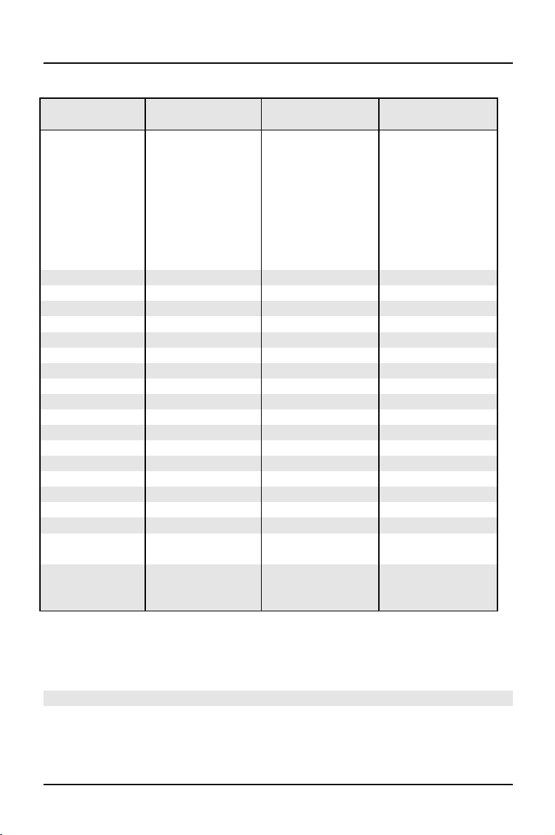
Possible screen resolution
Depending on the operating system used the screen resolutions in the following
table r efer to the screen controller on the system board. If you are using an external
screen controller, you will find details of supported screen resolutions in the
Operating Manual or Technical Manual supplied with the controller.
You can set the screen resolution under Windows 95 by selecting
Display - Settings.
You can set the screen resolution under MS-DOS using the
Control Panel -
SET-VGA program.
A26361-D943-Z120-14-7619 5
Introduction Possible screen resolution
Screen
resolution
Refresh rate (Hz) Horizontal-
rate (kHz) **
Max. number of
colors
640x350 70 31,5 16
640x350 84 38 16
640x480 60 31,5 16777216
640x480 75 37,5 16777216
640x480 85 43,4 16777216
640x480 100 50,6 16777216
720x400 70 31,5 16
720x400 84 38 16
800x600 60 38 65536
800x600 60 38 16777216
800x600 72 48 65536
800x600 72 48 16777216
800x600 75 47 65536
800x600 75 47 16777216
800x600 85 53,7 65536
800x600 85 53,7 16777216
800x600 100 63 65536
800x600 100 63 16777216
1024x768 87 interlaced 36 256
1024x768 87 interlaced 36 65536
1024x768 60 48,4 256
1024x768 60 48,4 65536
1024x768 75 60 256
1024x768 75 60 65536
1024x768 85 68,7 256 *
1024x768 85 68,7 65536 *
1024x768 100 81 256 *
1280x1024 87 interlaced 49 16
1280x1024 87 interlaced 49 256
1280x1024 60 63,7 256 *
1280x1024 75 80,4 256 *
* no 16 color mode
**
** The horizontal rate values may have a tolerance range of ± 0.3 kHz.
*** not for graphics processor Cirrus Logic CL-GD5446
The values marked are only available with a 2-Mbytes video memory.
6 A26361-D943-Z120-14-7619
Resource table Introduction
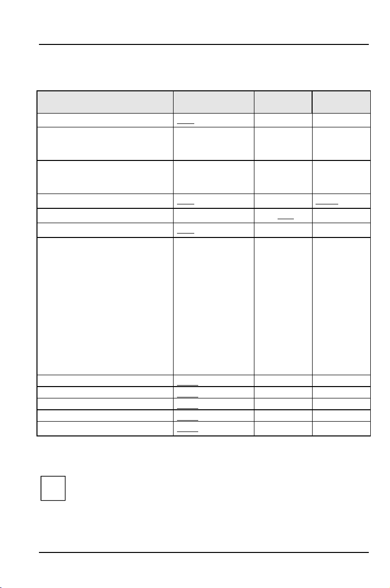
Resource table
possible IRQ Possible
Address
Keyboard IRQ1
Serial port COM2 / IrDA IRQ3,
IRQ4
Serial interfaceCOM1 / Chip card
reader
Floppydisk drive controller IRQ6 DMA2
Parallelinterface LPT1 IRQ5, IRQ7 0278, 0378 DMA1, DMA3
RTC IRQ8
Audio controller
Joystick:
Base address:
MPU 401:
USB controller IRQ11
Mouse controller IRQ12
Numeric processor IRQ13
IDE controller 1 IRQ14
IDE controller 2 IRQ15
The interrupts, addresses and DMAs set in the factory are underlined.
„PossibleIRQ“ = these interrupts can be used for your particular application
„Possibleaddress“ = this address can be used for your particular application
„PossibleDMA“ = this DMA can be used for your particular application
IRQ4,
IRQ3
IRQ5, IRQ7, IRQ9,
IRQ10
Adlib:
02F8, 03F8
02E8, 03E8
03F8, 02F8
03E8, 02E8
0200-0207
0220-022F
0240-024F
0260-026F
0280-028F
0300-0301
0330-0331
0338-038B
Possible
DMA
DMA1, DMA3,
DMA5, DMA7
Please note that a resource cannot be used bytwo applications at the same
i
time.
A26361-D943-Z120-14-7619 7

Important notes
p
p
p
p
p
p
y
p
g
g
p
g
p
g
t
g
p
m
Store this manual close to the device. If you pass on the device to third parties, you
should also pass on this manual.
Be sure to read thispage carefullyand note the information beforeyou
!
o
en the PC.
Please note the information
O
eratingManual of the PC.
Incorrect re
ex
losion. It is therefore essential to observe the instructions in the
cha
ter „Add-on modules“-„Replacingthe lithium battery“.
The lithium batterymust be replaced with an identical batteryor a batter
type r ecommended bythe manufacturer (CR2032).
Do not throw lithium batteries into the trashcan. It must be dis
accordance with local re
Data cables to peripheral devices must be adequately shielded.
Modules can become veryhot duringoperation. Make sureyou do no
touch modules when addingcomponents to the system board. There is a
!
dan
er of burns!
lacement of the lithium batterymaylead to a risk of
This board complies with the requirements of the EEC directive
89/336/EEC with re
Com
liance was tested in a typical PC configuration.
When installin
information in the O
receivin
device.
rovided in the chapter "Safety"inthe
osed of in
ulations concerningspecial waste.
ard to "Electromagnetic compatibility".
the board, refer to the specific installation
eratingManual or Technical Manual of the
The warrantyexpires if the device is damaged duringthe installation or
i
re
lacement of system expansions. Information on which syste
expansionsyou can use is available fromyour sales office or the customer
service.
A26361-D943-Z120-14-7619 9

Important notes
Boards with electrostatic sensitive devices (ESD) may be identified by labels.
When you handle boards fitted with ESDs, you must observe the following points
under all circumstances:
• You must always discharge yourself (e.g. by touching a grounded object)
before working.
• Theequipmentandtoolsyouusemustbefreeofstaticcharges.
• Pull out the power plug before inserting or pulling out boards containing
ESDs.
• Always hold boards with ESDs by their edges.
• Never touch pins or conductors on boards fitted with ESDs.
10 A26361-D943-Z120-14-7619

Settings in BIOS Setup
gop
y
The BIOS Setup menu allows you to set your hardware configuration and system
functions. In addition, the BIOS Setup displays technical information on the PC's
configuration.
When it is supplied, the PC is set to factory default settings which you can alter in
the
BIOS Setup menus. You can change these settings in BIOS Setup. Any changes
you make take effect as soon as you save the settings and quit the
The Operating Manual describes how to call the
BIOS Setup and change menu
entries.
You can select the following settings in the
Main - system functions
Advanced - advanced system configuration
Security - security features
Power - power-management features
BIOSFaX - quick start functions
Exit -saveandquit
BIOS Setup:
The various menus are described below with all settingoptions. Since the
i
settin
them ma
tions depend o nyour PC's hardware configuration, some of
not be offered in the BIOS setup.
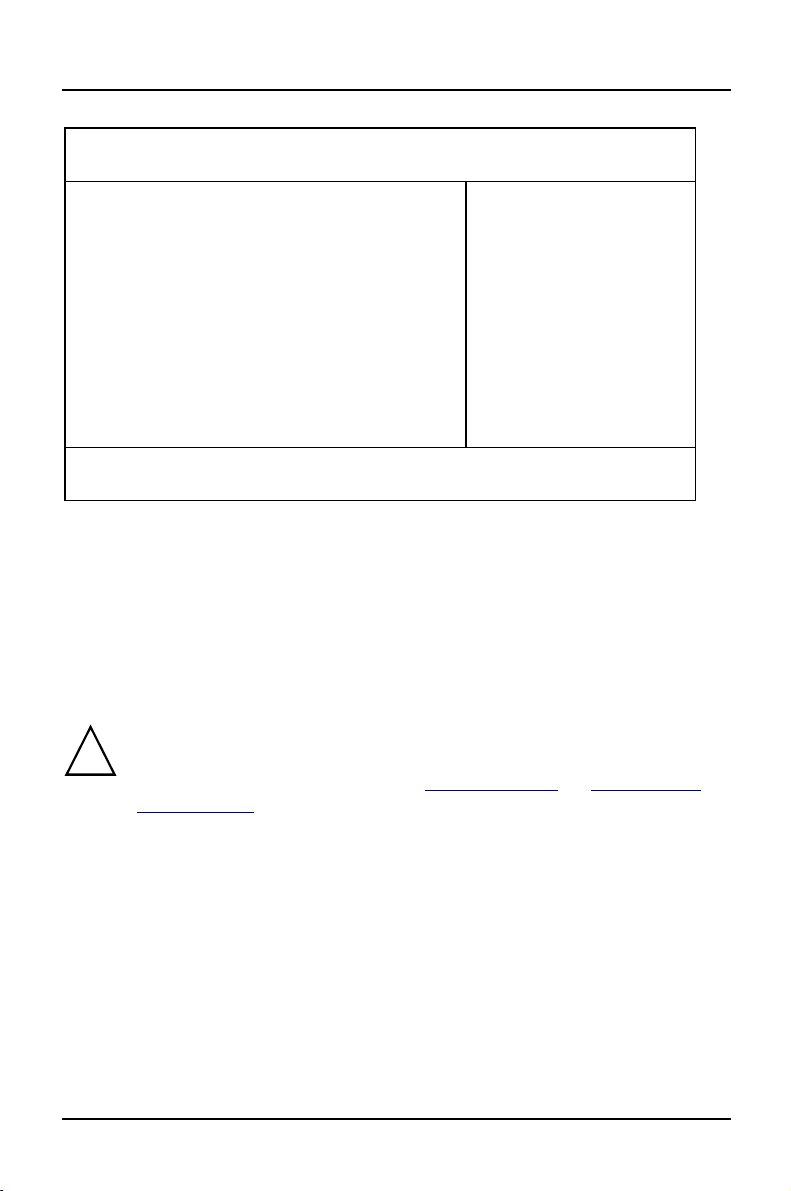
Main menu
In the Main menu you can set up the following:
• Time (in the field marked
• Date (in the field marked
• Floppy disk drive (in the field marked
• Hard disk drive (in the submenus of
• Display device (in the field marked
• System boot (in the submenus of
System Time)
System Date)
Diskette A or Diskette B)
Hard Disk)
Video Display)
Boot Options)
BIOS Setup.
A26361-D943-Z120-14-7619 11
Settings in BIOS Setup Main - system functions
M
y
g
Phoenix BIOS Setup
ain Advanced Security Power BIOSFaX Exit
System Time: [07:42:19]
System Date: [08/11/1995]
Diskette A: [1.4M]
Diskette B: [None]
Ê Hard Disk 1: 1 Gbyte
Ê Hard Disk 2: None
Ê Hard Disk 3: None
Ê Hard Disk 4: None
Ê Boot Options
Video Display: [EGA/VGA]
Base Memory: 640K
Extended Memory: 7M
F1 Help ↑↓ Select Item -/+ Change Values F9 Setup Defaults
ESC Exit
Example for Main menu
← → Select Menu Enter Execute Command F7 Previous Values
Item Specific Help
——————————————————————
System Time / System Date
The System Time field and the System Date field show the time and date respectively
according to the PC. The time is shown in the format hh:mm:ss
(hours:minutes:seconds) and the date is shown in the format mm/dd/yyyy
(month/day/year).
If the settingsintheSystem Time and System Date fields are frequentl
wrongwhenyoupower upthe computer, the lithium batteryis dead.
!
Chan
e the batteryas described in „Add-on modules“-„Replacingthe
lithium battery“).
Diskette A / Diskette B
These two fields are used to specify the type of floppy disk drive installed.
360K, 720K, 1.2M, 1.4M, 2.8M
The entry depends o n the floppy disk drive installed.
(Default entry Diskette A :
(Default entry Diskette A :
None A floppy disk drive is not installed.
(Default entry for Diskette B:).
12 A26361-D943-Z120-14-7619
1.4M).
1.4M).
Main - system functions Settings in BIOS Setup
y
d
g
M
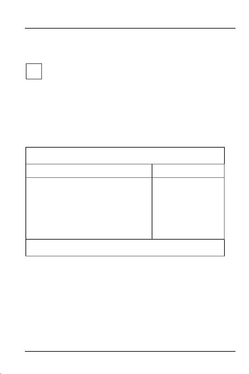
HardDisk1toHardDisk4-Harddiskdrives
call the submenu to make corresponding settings of the IDE hard disk drive.
You should change the default settingsonlyifyou are connectingan
i
additional IDE drive to one of the two IDE connectors.
The maximum transfer rate of two IDE drives connected to the same
connector is determined b
therefore be connected to the first IDE connector and identified as
Disk 1 or Hard Disk 2. Slower hard disks or other IDE drives (e.
ROM drives) should be connected to the second IDE connector and
identified as
Hard Disk 3 or Hard Disk 4.
the slowest one. Fast hard disks should
Har
.CD
The following description of the setting options for
, Hard Disk 3 and Hard Disk 4. The default settings depend on the installed
Disk 2
Hard Disk 1 also applies to Hard
drive.
Phoenix BIOS Setup
ain
Hard Disk 1: 1 Gbyte Item Specific Help
Autotype Hard Disk: [Press Enter]
Type: [User]
Cylinders: [ 1654]
Heads: [ 16]
Sectors/Track: [ 63]
Write Precomp: [None]
Transfer Mode: [Standard]
LBA Translation: [Enabled]
PIO Mode: [Fast PIO 3]
32 Bit I/O: [Enabled]
F1 Help ↑↓ Select Item -/+ Change Values F9 Setup Defaults
ESC Exit
Example forthe submenuHard Disk
← → Select Menu Enter Execute Command F7 Previous Values
A26361-D943-Z120-14-7619 13
Settings in BIOS Setup Main - system functions
y
y
k
y
p
p
Autotype Hard Disk
Onlyifyou have installed a new unrecorded IDE hard disk drive,you
should mark the
!
If
ou have set the hard diskparameters with Autotype Hard Disk,you can
onl
reduce the values.
If you have installed a new unrecorded IDE hard disk drive, you should mark the
Autotype Hard Disk field and press Enter. This has the effect of setting the optimum
values for the IDE hard disk drive. You can change these values if you set the
field to User.
Type - Hard Disk Type
Thisfieldisusedtospecifythetypeofharddiskdrive.
None You cannot change the hard disk parameters (Cylinders, Heads,
Sector/Track
installed.
1 to 39 The hard disk parameters (Cylinders, Heads, etc.) are preset.
Auto If the hard disk supports this mode, the setup menu reads the hard
disk parameters from the disk itself. You do not need to select the
parameters yourself.
User You can enter the hard disk parameters (Cylinders, Heads etc.)
yourself.
If you have set the hard disk parameters with
you can only reduce the values.
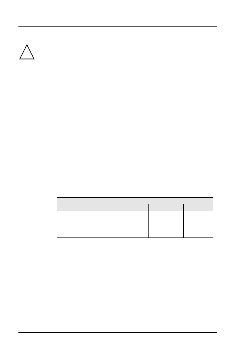
Examples of user-defined entries (IDE drives):
Hard dis
arameter 850 Mbyte 1,2 Gbyte 1,6 Gbyte
Cylinders 1654 2484 3148
Heads 16 16 16
Sectors 63 63 63
Write Precom
Autotype Hard Disk field.
Type
and Write Precomp). An IDE drive has not been
Autotype Hard Disk,
hard disk capacit
None None None
CD If an ATAPI CD-ROM drive is installed, this entry enables you to
boot from the CD-ROM drive.
14 A26361-D943-Z120-14-7619

Main - system functions Settings in BIOS Setup
p
y
Cylinders, Heads, Sectors/Track, Write Precomp - hard disk parameter
These hard disk parameters are set in accordance with the IDE hard disk drive. If
you want to change the hard disk parameters manually, set the
Transfer Mode
This field specifies the transfer mode for the IDE hard disk drive.
Standard One block is transferred for each interrupt (default entry).
2 Sectors, 4 Sectors, 6 Sectors, 8 Sectors, 16 Sectors
The set number of blocks (sectors) is transferred for each interrupt.
LBA Translation - Addressing
This field enables and disables the LBA (Logical Block Addressing) mode. LBA
mode allows you to install and use IDE hard disks with a capacity of more than
528 Mbytes. If a hard disk supports LBA mode, you can use the full capacity of
the IDE hard disk.
The default entry depends on the installed IDE hard disk drive. Change the default
entries only if you are installing another hard disk drive.
You mayonlyuse IDE drives in the LBA mode selected when theywere
set u
!
Enabled If the hard disk supports LBA and it has a capacity of more than
Disabled The BIOS uses the hard disk parameters and supports a maximum
. In other words, ifyou set upa hard disk with LBA mode disabled,
ou mayonlyoperate the hard disk with LBA mode disabled.
528 Mbytes, the BIOS translates the hard disk parameters,
allowing the disk's full capacity to be used. This allows the disk's
full capacity to be used.
If the hard disk does not support LBA, its parameters are not
translated.
capacity of 528 Mbytes.
Type field to User.
A26361-D943-Z120-14-7619 15
Settings in BIOS Setup Main - system functions
M
PIO Mode - Transfer rate
The PIO (Programmed Input Output) Mode defines the transfer rate of the IDE
hard disk drive.
Standard 0,8 Mbyte/s to 2 Mbytes/s (default entry)
Fast PIO 1 2Mbytes/sto4Mbytes/s
Fast PIO 2 4Mbytes/sto5Mbytes/s
Fast PIO 3 5Mbytes/sto10Mbytes/s
Fast PIO 4 more than 10 Mbyte/s
32 Bit I/O - Bus width for data transfer
This field specifies the width of data transmission between the processor and the
IDE controller.
Enabled The data transfer is 32 bits in width at the PCI bus. This enhances
performance (default entry).
Disabled The data transfer is 16 bits in width.
Boot Options
calls the submenu in which you can select the settings for system startup of the PC.
Phoenix BIOS Setup
ain
Boot Options Item Specific Help
POST Error Halt: [Halt On All Errors]
Quick Boot: [Disabled]
Quiet Boot: [Disabled]
Boot Sequence: 1. Diskette
F1 Help ↑↓ Select Item -/+ Change Values F9 Setup Defaults
ESC Exit
Example forsubmenu Boot Options
← → Select Menu Enter Execute Command F7 Previous Values
2. Hard Disk
3. CD ROM
16 A26361-D943-Z120-14-7619

Main - system functions Settings in BIOS Setup
POST Error Halt - Aborting system startup
defines whether the system startup is to be aborted and the system halted when an
error is detected.
Halt On All Errors
If the self-test detects an error, system startup is aborted after the
self-test, and the system is halted (default entry).
No Halt On Any Errors
The system startup is not aborted. The error is ignored as far as
possible. The error is ignored as far as possible.
Quick Boot
can reduce the extent of the self-test and thus accelerate the system startup.
Enabled When the PC is switched on, the quick self-test is carried out, in
which the floppy disk drives are not checked.
Disabled When the PC is switched on, the complete PC configuration is
tested (default entry).
Quiet Boot
Instead of a start information a logo is displayed on the screen.
Enabled The logo is displayed on the screen. A switch to the start
information is made if you press the
Disabled The start information is d isplayed on the screen (default entry).
[Esc]
[Esc] key or if errors occur.
[Esc][Esc]
A26361-D943-Z120-14-7619 17
 Loading...