

Page 1

System board D931
Technical Manual
Page 2

Dieses Handbuch wurde auf Recycling-Papier gedruckt.
This manual has been printed on recycled paper.
Ce manuel est imprimé sur du papier recyclé.
Este manual ha sido impreso sobre papel reciclado.
Questo manuale è stato stampato su carta da riciclaggio.
Denna handbok är tryckt på recyclingpapper.
Dit handboek werd op recycling-papier gedrukt.
Herausgegeben von/Published by
Siemens Nixdorf Informationssysteme AG
D-33094 Paderborn
D-81730 München
Bestell-Nr./Order No.: A26361-D931-Z121-5-7619
Printed in the Federal Republic of Germany
AG 1296 12/96
A26361-D931-Z121-5-7619
A26361-D931-Z121-5-7619A26361-D931-Z121-5-7619
A26361-D931-Z121-1-7619
Page 3

Is there ...
...any technical problem or other
question you need clarified?...
Please contact:
• one of our IT Service Shops
• your sales partner
• your sales office
You will find the addresses of the
IT Service Shops in the enclosed
warrantycoupon booklet.
... anything you want to tell us
about this manual?
Please send us your comments quoting
the order number of the manual.
Siemens NixdorfInform ations sy stem eA G
Redaktion BS2000 OS ID4
Otto-Hahn-Ring 6
D-81730 München
Germany
Page 4

Page 5

Introduction
Important notes
System board D931
Technical Manual
Settings in BIOS-Setup
Jumper settings
Add-on modules
Error messages
Index
December 1996 edition
Page 6

Your training needs . . .
The Siemens Nixdorf Training Centers offer you a wide range of training courses
in information technology and on IT products and other subjects - onsite near to
your workplace or offsite at one of our training centers.
Contact us for information on consulting, course schedules and selfstudy material
Please fax:
Fax: ++49 89 636-42945
Or write to:
Siemens Nixdorf Informationssysteme AG
Training Center, Beratungsservice
D-81730 München
Germany
Adaptec is a registered trademark of Adaptec Inc.
Intel,the Logo „intel inside“ and Pentium are registered trademarks and OverDrive is a trademark of
IntelCorporation, USA.
Microsoft, MS, MS-DOS, Windows and Windows95 are registered trademarks of Microsoft
Corporation.
PS/2 and OS/2 Warp are registered trademarks of International Business Machines, Inc.
All other trademarks referenced are the trademarks or registered trademarks of their respective owners,
whose protected rights are acknowledged.
Copyright ã SiemensNixdorf InformationssystemeAG 1995.
All rights, including rights of translation, reproduction by printing, copying or similar methods, even
of parts are reserved.
Offenders will be liable for damages.
All rights, including rights created by patent grant or registration of a utility model or design, are
reserved.
Delivery subject to availability; right of technical modifications reserved.
Page 7

Contents
Introduction........................................................................................................... 1
Notational conventions............................................................................................ 1
Features................................................................................................................... 2
Ports and connectors ............................................................................................... 3
Interrupt table.......................................................................................................... 4
Important Notes .................................................................................................... 5
Modules with ESDs ......................................................................................... 5
CE certificate ................................................................................................... 6
Program with time loops ......................................................................................... 6
Settings in BIOS Setup ......................................................................................... 7
Main menu - System settings................................................................................... 7
System Time / System Date ............................................................................. 8
Diskette A / Diskette B .................................................................................... 8
HardDisk1toHardDisk4............................................................................. 9
Boot Options.................................................................................................. 12
Video Display................................................................................................ 13
Base Memory................................................................................................. 13
Extended Memory.......................................................................................... 13
Menu Advanced - Making advanced system settings............................................ 14
Cache Memory............................................................................................... 15
Shadow Memory............................................................................................ 17
Peripheral Configuration................................................................................ 18
PCI Configuration.......................................................................................... 21
Advanced System Configuration.................................................................... 22
Plug & Play O/S............................................................................................. 23
Reset Configuration Data............................................................................... 23
Large Disk Access Mode............................................................................... 24
Menu Security - Setting up the security features................................................... 25
Setup Password / System Password ............................................................... 25
Set Setup Password........................................................................................ 26
SetupPasswordLock..................................................................................... 26
Set System Password...................................................................................... 26
System Password Mode ................................................................................. 26
System Load................................................................................................... 27
Setup Prompt.................................................................................................. 27
Virus Warning................................................................................................ 27
A26361-D931-Z121-5-7619
Page 8

Contents
Diskette Write - Write protection for floppy disk drive .................................28
Flash Write - Write protection for System BIOS ...........................................28
Soft Power Off ...............................................................................................28
Remote Power On..........................................................................................28
Power menu - Setting energy saving functions......................................................29
APM...............................................................................................................29
Power Management Mode..............................................................................30
Standby Timeout............................................................................................30
Hard Disk Timeout.........................................................................................30
Standby CPU Speed .......................................................................................31
Wakeup Event................................................................................................32
Exit menu - Exiting BIOS Setup............................................................................33
Save Changes & Exit......................................................................................33
Discard Changes & Exit .................................................................................33
Get Default Values.........................................................................................33
Load Previous Values.....................................................................................33
Save Changes .................................................................................................33
Jumper settings....................................................................................................35
Write protection for System BIOS - jumper FLP ..................................................35
Recovering System BIOS - jumper RCV ..............................................................36
Write protection for floppy disk drive - jumper FDP ............................................36
Clock speed - jumper F0-F2 and CF0-CF3 ...........................................................37
Add-on modules...................................................................................................39
Upgrading main memory .......................................................................................39
Installing memory modules ............................................................................40
Removinga memory module..........................................................................40
Replacing the processor.........................................................................................41
Replacing the lithium battery.................................................................................43
Error messages.....................................................................................................45
Messages d'erreur................................................................................................47
Mensajes de error................................................................................................49
Messagi di errore.................................................................................................51
Felmeddelanden...................................................................................................53
A26361-D931-Z121-5-7619
Page 9

Contents
Foutmeldingen..................................................................................................... 55
Index..................................................................................................................... 57
A26361-D912-Z100-1-19
Page 10

Page 11

Introduction
This description applies for the system board D931 with PCI bus (Peripheral
Component Interconnect).
Notational conventions
The meanings of the symbols and fonts used in this manual are as follows:
This indicates instructions which it is essential to observe. Failure to do
!
so may endanger your health, the operational integrity and electrical
safety of your PC, or the security of your data.
This symbol is f ollowed by supplementary information, remarks and tips.
i
Ê Texts which follow this symbol describe activities that must be performed in
the order shown.
Ë This symbol means that you must enter a blank space at thispoint.
↵
This symbol means that you must press the Enter key.
Texts in this typeface are screen outputs from the PC.
Texts in this bold typeface are the entries you make via the keyboard.
Texts in italics indicate commands or menu items.
"Quotation marks" indicate highlighted text and names of chapters."
A26361-D931-Z121-5-7619 1
Page 12

Introduction Features
Features
• 64-bit microprocessor Pentium with 16 Kbytes internal cache (first-Level
Cache, 8 Kbytes data cache, 8 Kbytes address cache) or
OverDrive processor for Pentium Pro
• Memory configuration on system board: 8 Mbytes to 256 Mbytes
• 256 Kbytes Flash BIOS
• PCI bus
• IDE hard disk controller connected to PCI bus for up to four IDE drives
(e.g. IDE hard disk drives, ATAPI CD ROM drive)
• Real-time clock/calendar with integrated batterybackup
• Floppy disk controller (up to 2.88 Mbytes format)
• Bus interface for p latter
• Connector for remote-on (fax/modemboard), serial port (SER2, TTL),
chipcard reader and infrared interface
• Parallel port (ECP- and EPP-compatible)
• 2 serial ports
• PS/2 mouse port
• PS/2 keyboard port
• Piezo loudspeaker
• Security functions
2 A26361-D931-Z121-5-7619
Page 13
Ports and connectors Introduction
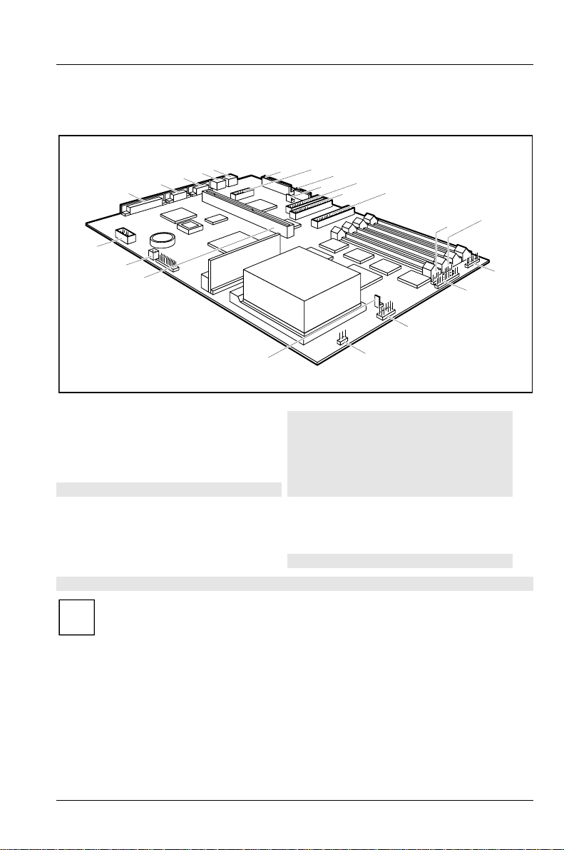
Ports and connectors
5
4
3
2
1
22
21
20
19
1 = Parallel interface
2 = Serial port 2
3 = Serial port 1
4= PS/2mouseport
5= PS/2keyboardport
6 = Connector for power supply
7 = Connector for chipcard reader connection
8 = Connector for power supply 3,3 V
9 = Soft off power supply
10 = Connector for floppydisk drive
11 = Connector 1 for IDE drives 1 and 2
(e.g.harddiskdrive)
The connectors marked do not have to be present on the system board.
7
6
12 = Connector 2 for IDE drives 3 and 4
13 = Connector for device loudspeaker
14 = Connector for infrared interface
15 = Connector for LED indicators
16 = Connector for LED indicators
17 = Connector for infrared interface and LED
18 = Connector for fan
19 = Connector for On/Off switch
20 = Bus interface
21 = Connector for remote-on
22 = Connector for Serial port 2 SER2 (TTL)
8
9
11
indicators
10
18
12
17
13
14
15
16
If the connector for the chipcard reader port is used, no device may be
i
connected to serial interface 1.
If the connector for the serial interface SER2 (TTL) is used, no device
may be connected to the serial interface 2.
A26361-D931-Z121-5-7619 3
Page 14

Introduction Interrupt table
Interrupt table
Address Assigned IRQ Possible IRQ
Keyboard IRQ1
Cascade IRQ2
COM2 dispatcher 02F8 IRQ3
Serial interface COM1 03F8 IRQ4
IRQ5
Floppy disk drive controller IRQ6
Parallel interface LPT1 IRQ7
RTC IRQ8
IRQ9
IRQ10
IRQ11
Mouse controller IRQ12
Numeric processor IRQ13
IDE controller 1 IRQ14
IDE controller 2 IRQ15
„Assigned IRQ“ = interrupts assigned as shipped
„PossibleIRQ“ = these interrupts can be used for your particular application
Please note that an interrupt cannot be used by two applications at the
i
same time.
4 A26361-D931-Z121-5-7619
Page 15

Important Notes
Be sure to read this page carefullyand note the information before you
!
open the PC.
Please note the information provided in the chapter "Safety" in the
Operating Manual of the PC.
Incorrect replacement of the lithium battery may lead to a risk of
explosion. It is therefore essential to observe the instructions in the
section "Replacing the lithium battery“.
The lithium battery must be replaced with an identical battery or a battery
type recommended by the manufacturer (CR2032).
Do not throw lithium batteries into the trashcan. Your vendor or dealer or
their authorized representatives will take used batteries back free of
charge so that they can be recycled or disposed of in the proper manner.
Connecting cable for peripherals must be adequately insulated to avoid
interference.
ADVARSEL
Lithiumbatteri - Eksplosionsfare ved fejlagtig håndtering. Udskiftningmå
!
kun ske med batteri af samme fabrikat og type. Lever det brugte batteri
tilbage til leverandøren.
ADVARSEL
Eksplosjonsfare ved feilaktig skifte av batteri. Benytt samme batteritype
!
eller en tilsvarende type anbefalt av apparatfabrikanten. Brukte batterier
kasseres i henhold til fabrikantens instruksjoner.
VARNING
Eksplosionsfara vid felaktigt batteribyte. Använd samma batterityp eller
!
en ekvivalent typ som rekommenderas av apparattillverkarenfabrikanten.
Kassera använt batteri enligt fabrikantens instruktion.
VAROITUS
Paristo voi räjähtää, jos se on virheellisesti asennettu. Vaihda paristo
!
ainoastaan laitevalmistajan suosittelemaan tyyppiin. Hävitä käytetty
paristo valmistajan ohjeiden mukaisesti.
Modules with ESDs
Modules with electrostatic sensitive devices (ESD) maybe identified by labels.
A26361-D931-Z121-5-7619 5
Page 16

Important Notes Program with time loops
When you handle modules fitted with ESDs, you must observe the following
points under all circumstances:
• When you handle modules fitted with ESDs, you must always discharge
yourself (e.g. by touching a grounded object) before working.
• Theequipmentandtoolsyouusemustbefreeofstaticcharges.
• Pull out the power plug before inserting or pulling out modules containing
ESDs.
• Always hold modules with ESDs by their edges.
• Never touch pins or conductors on modules fitted with ESDs.
CE certificate
This board complies with the requirements of the EEC directive
89/336/EEC with regard to "Electromagnetic compatibility".
Conformity was tested in the typical configuration of a Personal
Computer.
When installing the board, observe the specific installation notes in
the Operating Manual or Technical Manual for the appropriate
device.
Program with time loops
Problems can occur with programs in which time loops have been implemented
through software loops. This applies in particular to older programs which were
written for 8 MHz processors.
6 A26361-D931-Z121-5-7619
Page 17

Settings in BIOS Setup
The BIOS Setup menu allows you to set your hardware configuration and system
functions. In addition, the
configuration.
When it is supplied, the PC is set to factory default settings which you can alter in
the
BIOS Setup menus. Any changes you make take effect as soon as y ou save the
settings and quit the
The Operating Manual describes howto call the
entries.
You can select the following settings in the BIOS Setup:
Main - system functions
Advanced - advanced system configuration
Security - security features
Power - energy saving functions
Exit -saveandquit
The various menus are described below with all settingoptions. Since the
i
setting options depend on your PC's hardware config uration, some of
them may not be offered in the BIOS setup.
Main menu - System settings
In the Main menu you can set up the following:
• Time (in the field marked
• Date (in the field marked
• Floppy disk drive (in the field marked
• Hard disk drive (in the submenus of
• System boot (in the submenus of
• Display device (in the field marked
BIOS Setup displays technical information on the PC's
BIOS Setup.
BIOS Setup and change menu
System Time)
System Date)
Diskette A or Diskette B)
Hard Disk)
Boot Options)
Video Display)
A26361-D931-Z121-5-7619 7
Page 18

Settings in BIOS Setup Main menu - System settings
M
Phoenix BIOS Setup Copyright 1985-94 Phoenix Technologies Ltd.
ain Advanced Security Power Exit
System Time: [07:42:19]
System Date: [08/11/1995]
Diskette A: [1.4M]
Diskette B: [None]
Ê Hard Disk 1: 850 Mbyte
Ê Hard Disk 2: None
Ê Hard Disk 3: None
Ê Hard Disk 4: None
Ê Boot Options
Video Display: [EGA/VGA]
Base Memory: 640K
Extended Memory: 7M
F1 Help ↑↓ Select Item -/+ Change Values F9 Setup Defaults
ESC Exit
Example for Main menu
← → Select Menu Enter Execute Command F7 Previous Values
Item Specific Help
——————————————————————
System Time / SystemDate
The System Time field and the System Date field showthe time and date respectively
according to the PC. The time is shown in the format hh:mm:ss
(hours:minutes:seconds) and the date is shown in the format mm/dd/yyyy
(month/day/year).
If the settings in the System Time and System Date fields are frequently
!
wrong when you power up the computer, the lithiumbattery is dead.
Change the battery as described in "Replacing the lithium battery“.
Diskette A / Diskette B
These two fields are used to specify the type of floppy disk drive installed.
360K
, 720K, 1.2M, 1.4M, 2.8M
The entry depends on the floppy disk drive installed.
(Default entry Diskette A : 1.4M)
None A floppy disk drive is not installed.
(Default entry for Diskette B:)
8 A26361-D931-Z121-5-7619
Page 19

Main menu - System settings Settings in BIOS Setup
M
HardDisk1toHardDisk4
call the submenu to make corresponding settings of the IDE hard disk drive.
You should change the default settings only if you are connecting an
i
additional IDE drive to one of the two IDE connectors.
The maximum transfer rate of two IDE drives connected to the same
connector is determined by the slower of the two. Fast hard disks
should therefore be connected to the first IDE connector and identified
as
Hard Disk 1 or Hard Disk 2; slower hard disks or other IDE drives
(e.g. CD ROM drives) should be connected to the second IDE
connector and identified as
Hard Disk 3 or Hard Disk 4.
The following description of the setting options for
, Hard Disk 3 and Hard Disk 4. The default settings depend on the installed
Disk 2
Hard Disk 1 also applies to Hard
drive.
Phoenix BIOS Setup Copyright 1985-94 Phoenix Technologies Ltd.
ain
Hard Disk 1: 850 Mbyte Item Specific Help
Autotype Hard Disk: [Press Enter]
Type: [User]
Cylinders: [ 1654]
Heads: [ 16]
Sectors/Track: [ 63]
Write Precomp: [None]
Transfer Mode: [Standard]
LBA Translation: [Disabled]
PIO Mode: [Standard]
32 Bit I/O: [Enabled]
F1 Help ↑↓ Select Item -/+ Change Values F9 Setup Defaults
ESC Exit
Example for the submenu Hard Disk 1
← → Select Menu Enter Execute Command F7 Previous Values
Only if you have installed a new unrecorded IDE hard disk drive, you
!
should mark the
If you have set the hard d isk parameters with
Autotype Hard Disk field.
Autotype Hard Disk, you can
only reduce the values.
A26361-D931-Z121-5-7619 9
Page 20

Settings in BIOS Setup Main menu - System settings
If you have installed a new unrecorded IDE hard disk drive, you should mark the
Autotype Hard Disk field and press Enter. This has the effect of setting the optimum
values for the IDE hard disk drive. You can change these values ifyou set the
Type
field to User.
Type - Hard Disk Type
This field is used to specify the type of hard disk drive installed.
None You cannot change the hard disk parameters (Cylinders, Heads,
Sector/Track
and Write Precomp). An IDE drive has not been
installed.
1 to 39 The hard disk parameters(Cylinders, Heads, etc.) are pr eset.
Auto If the hard disk supports this mode, the setup menu reads the hard
disk parameters from the disk itself and sets them automatically.
You do not need to select the parameters yourself.
User You can enter the hard disk parameters (Cylinders, Heads etc.)
yourself.
If you have set the hard d isk parameters with
Autotype Hard Disk,
you can only reduce the values.
Examples of user-defined entries (IDE drives):
hard disk hard disk capacity
parameter 850 Mbyte 1Gbyte 1,6 Gbyte
Cylinders 1654 2097 3148
Heads 16 16 16
Sectors 63 63 63
Write Precomp None None None
CD If an ATAPI CD-ROM drive is mounted, this entry enables you to
boot from the CD-ROM drive.
Cylinders, Heads, Sectors/Track, Write Precomp - hard disk parameter
These hard disk parameters are set inaccordance with the IDE hard disk drive. If
you want to change the hard disk parameters manually, set the
Type field to User.
10 A26361-D931-Z121-5-7619
Page 21

Main menu - System settings Settings in BIOS Setup
Transfer Mode
This field specifies the transfer mode for the IDE hard disk drive.
Standard One block is transferred for each interrupt (default entry).
2 Sectors, 4 Sectors, 6 Sectors, 8 Sectors, 16 Sectors
The set number of blocks (sectors) is transferred for each interrupt.
LBA Translation
This field enables and disables the LBA (Logical Block Addressing) mode. LBA
mode allows you to install and use hard disks with a capacity of more than 528
Mbytes. If a hard disk supports LBA mode, you can use the full capacity of the
IDE hard disk.
The default entry depends on the installed IDE hard disk drive. Change the default
entries only if you are installing another hard disk drive.
You may only use IDE drives in the LBA mode selected when they were
!
set up. In other words, if you set up a hard disk with LBA mode
you may only operate the hard disk with LBA mode
Enabled If the hard disk supports LBA and it has a capacity of more than
disabled.
disabled,
528 Mbytes, the BIOS translates the hard disk parameters,
allowing the disk's full capacity to be used.
If the hard disk does not support LBA, its parameters are not
translated.
Disabled The BIOS uses the hard disk parameters and supports a maximum
capacity of 528 Mbytes.
PIO Mode
The PIO (Programmed Input Output) Mode defines the transfer rate of the IDE
hard disk drive.
Standard 0,8 Mbyte/s to 2 Mbytes/s (default entry)
Fast PIO 1 2Mbytes/sto4Mbytes/s
Fast PIO 2 4Mbytes/sto5Mbytes/s
Fast PIO 3 5Mbytes/sto10Mbytes/s
Fast PIO 4 10Mbyte/sto16Mbyte/s
A26361-D931-Z121-5-7619 11
Page 22

Settings in BIOS Setup Main menu - System settings
M
32 Bit I/O - Bus width for data transfer
specifies the width of data transmission between the processor and the IDE
controller.
Enabled The data transfer is 32 bits in width at the PCI bus (default entry).
This enhances performance.
Disabled The data transfer is 16 bits in width.
Boot Options
calls the submenu in which you can select the settings for system startup of the PC.
Phoenix BIOS Setup Copyright 1985-94 Phoenix Technologies Ltd.
ain
Boot Options Item Specific Help
POST Error Halt: [Halt On All Errors]
Quick Boot: [Disabled]
Boot Sequence: 1. Diskette
2. Hard Disk
3. CD ROM
F1 Help ↑↓ Select Item -/+ Change Values F9 Setup Defaults
ESC Exit
Example for submenu Boot Options
← → Select Menu Enter Execute Command F7 Previous Values
POST Error Halt - Aborting systemstartup
defines whether the system startup is to be aborted and the system halted when an
error is detected.
Halt On All Errors
If the self-test detects anerror, system startup is aborted after the
self-test, and the system is halted (default entry).
No Halt On Any Errors
The system startup is not aborted. The error is ignored as far as
possible.
12 A26361-D931-Z121-5-7619
Page 23

Main menu - System settings Settings in BIOS Setup
Quick Boot
can reduce the extent of the self-test and thus accelerate the system startup.
Enabled When the PC is switched on, the quick self-test is carried out, in
which the floppy disk drives are not checked.
Disabled When the PC is switched on, the complete PC configuration is
tested (default entry).
Boot Sequence
defines the sequence in which the system BIOS searches the drives for system files
to start the operating system. If you wish to change this sequence, place the cursor
on the entry for the drive you to which wish to move forward ( +
key).
(-
key) or back
Default entry:
1. Diskette
2. Hard Disk
3. CD ROM
Video Display
This field is used to specify the type of monitor connected.
EGA/VGA
, Color 80, Monochrome
Default entry: EGA/VGA
Base Memory
This field indicates the size of the available base memory below 1 Mbyte.
Extended Memory
This field indicates the size of the memory above 1 Mbyte.
A26361-D931-Z121-5-7619 13
Page 24

Settings in BIOS Setup Advanced system settings
A
Menu Advanced - Making advanced system settings
Change the default settings only for special applications. Incorrect
!
settings can cause malfunctions.
You can make the following system settings in the
• Cache (in the
Cache Memory submenu)
• Copy BIOS sections to the RAM (in the
• Interfaces and controllers (in the
• PCI functionality (in the
PCI Configuration submenu)
• Data access to hard disk (in the
• Plug&Play functionality (in the
• Configuration data (in the
• Hard disk access (in the
Phoenix BIOS Setup Copyright 1985-94 Phoenix Technologies Ltd.
Main
Setting items on this menu to incorrect
values
may cause your system to malfunction.
Ê Cache Memory
Ê Shadow Memory
Ê Peripheral Configuration
Ê PCI Configuration
Ê Advanced System Configuration
Plug & Play O/S: [Yes]
Reset Configuration Data: [No]
Large Disk Access Mode: [DOS]
dvanced Security Power Exit
Large Disk Access Mode field)
Warning!
Peripheral Configuration submenu)
Advanced System Configuration submenu)
Plug and Play O/S field)
Reset Configuration Data field)
Advanced menu:
Shadow Memory submenu)
——————————————————————
Item Specific Help
F1 Help ↑↓ Select Item -/+ Change Values F9 Setup Defaults
ESC Exit
Example for the Advanced menu
← → Select Menu Enter Execute Command F7 Previous Values
14 A26361-D931-Z121-5-7619
Page 25

Advanced system settings Settings in BIOS Setup
A
Cache Memory
calls the submenu in which you can make the settings for cache
Phoenix BIOS Setup Copyright 1985-94 Phoenix Technologies Ltd.
Cache: [Enabled]
Cache System BIOS Area: [Write Protect]
Cache Video BIOS Area: [Write Protect]
Cache DRAM Memory Area: [Write Back]
Cache Memory Regions:
C800 - CBFF: [Disabled]
CC00 - CFFF: [Disabled]
D000 - D3FF: [Disabled]
D400 - D7FF: [Disabled]
D800 - DBFF: [Disabled]
DC00 - DFFF: [Disabled]
dvanced
Cache Memory Item Specific Help
F1 Help ↑↓ Select Item -/+ Change Values F9 Setup Defaults
ESC Exit
Example for submenu Cache Memory
← → Select Menu Enter Execute Command F7 Previous Values
Cache
This field switches the cache on and off. The cache is a buffer to which parts o f the
main memory and BIOS canbe temporarily copied. The PC's performance is
higher when the cache is switched on.
You must disable the cache if :
• the access time is too short for older applications
• you are installing
Enabled The cache is used.
Disabled The cache is disabled All cache-related settings are then without
OS/2 Warp.
effect.
A26361-D931-Z121-5-7619 15
Page 26

Settings in BIOS Setup Advanced system settings
Cache System BIOS Area / Cache Video BIOS Area
Prerequisite: The
The video BI OS and the System BIOS can be mapped in the cache using
System BIOS Area
Cache field must contain Enabled.
Cache
and Cache Video BIOS Area. If the contents of the BIOS are in the
cache, the device's performance is enhanced.
Write Protect The corresponding BIOS (write access) is mapped in the cache
(Default entry).
Disabled The contents of the memory are not mapped in the cache .
Cache DRAM Memory Area
Prerequisite: The
Parts of the main memory can be mapped in the cache using
. If the contents of the memory are in the cache, the device's performance is
Area
Cache field must contain Enabled.
Cache DRAM Memory
enhanced.
Write Through The contents of the memory are simultaneously mapped in the
cache and written in the main memory. The main memory and the
cache contain the same information.
Write Back The contents of the memory are mapped in the cache and written in
the main memory only as required. The main memory and the
cache do not containthe same information. (Default entry)
Disabled The contents of the memory are not mapped in the cache .
Cache Memory Regions
Condition: The Cache field must be set to Intern only or Intern and Extern.
Cache Memory Regions lets you specify the BIOS ROM areas that should be mapped
to the cache. Mapping the BIOS ROM areas to the cache increases system
performance.
Enabled The relevant ROM area is mapped to the cache.
Disabled The relevant ROM area is not mapped to the cache (default entry).
16 A26361-D931-Z121-5-7619
Page 27

Advanced system settings Settings in BIOS Setup
A
Shadow Memory
calls the submenu in which you can specify which parts of the ROM (Read Only
Memory) are to be copied to the faster RAM (Random Access Memory) at system
startup.
Phoenix BIOS Setup Copyright 1985-94 Phoenix Technologies Ltd.
System Shadow: Enabled
Video Shadow: [Enabled]
Shadow Memory Regions:
dvanced
Shadow Memory Item Specific Help
C800 - CBFF: [Disabled]
CC00 - CFFF: [Disabled]
D000 - D3FF: [Disabled]
D400 - D7FF: [Disabled]
D800 - DBFF: [Disabled]
DC00 - DFFF: [Disabled]
F1 Help ↑↓ Select Item -/+ Change Values F9 Setup Defaults
ESC Exit
Example for submenu Shadow Memory
← → Select Menu Enter Execute Command F7 Previous Values
System Shadow
This field is always
Enabled, because the System BIOS is automatically copied to
the faster RAM.
Video Shadow
This field allows you to copy the video BIOS to fast RAM. Copying the video
BIOS to fast RAM increases system performance.
Enabled The video BIOS is copied to fast RAM (default entry).
Disabled The video BIOS is not copied to fast RAM. This setting is not
effective unless an external monitor controller is used.
A26361-D931-Z121-5-7619 17
Page 28

Settings in BIOS Setup Advanced system settings
A
Shadow Memory Regions
Shadow Memory Regions allows you to copy ROM areas to fast RAM. Copying
ROM areas to fast RAM increases system performance.
Enabled The ROM area is copied to fast RAM.
Disabled The ROM area is not copied to fast RAM (default entry).
Peripheral Configuration
calls the submenu in which you can set the interfaces and controllers.
Phoenix BIOS Setup Copyright 1985-94 Phoenix Technologies Ltd.
Serial 1: [Auto]
Serial 2: [Auto]
Serial 2 Mode: [Standard]
Parallel: [Auto]
Parallel Mode: [Printer]
Diskette Controller: [Enabled]
Hard Disk Controller: [Primary And
Secondary]
Mouse Controller: [Enabled]
dvanced
Peripheral Configuration Item Specific Help
F1 Help ↑↓ Select Item -/+ Change Values F9 Setup Defaults
ESC Exit
Example for submenu Peripheral Configuration
← → Select Menu Enter Execute Command F7 Previous Values
18 A26361-D931-Z121-5-7619
Page 29

Advanced system settings Settings in BIOS Setup
Serial 1 / Serial 2 - Serial port
This field selects the address and the interrupt used to access the relevant serial
port.
3F8h, IRQ4, 2F8h, IRQ3, 3E8h, IRQ4, 2E8h, IRQ3,
The serial port is set to the shown address and interrupt.
Auto The serial port is automatically set to the next available
combination (address, interrupt) (Default entry).
Disabled The serial port is disabled. The corresponding interrupt and
address are free.
Serial 2 Mode
This field defines whether the second serial port is used as the standard port or as
the infrared interface.
If you wish to use infrared data transfer, aninfrared interface with the associated
hardware must be incorporated in the device.
Standard The port operates as a serial port. (Default)
IRDA ( Infra-Red Data Association) The serial port permits infrared data
transfer up to 115 kbit/s. External serial port 2 does not function.
Parallel
This field selects the address and the interrupt used to access the parallel port.
378h, IRQ7, 278h, IRQ5, 3BCh, IRQ7
The parallel port is set to the shown address and interrupt.
Auto The parallel port is automaticallyset to the next available
combination (address, interrupt) (Default entry).
Disabled The parallel port is disabled.
A26361-D931-Z121-5-7619 19
Page 30

Settings in BIOS Setup Advanced system settings
Parallel Mode
Thisfieldisusedtospecifywhethertheparallelportistobeusedasabidirectional input/output port or just as an output port.
ECP and EPP transfer modes
allow faster transfer rates of 2 and 2.4 Mbytes/s. These modes will only work with
peripheral devices which support them. The field Parallel must be set to
278h.
Printer The port functions as an output port only (default entry).
Bidirection Data can be transferred in both directions across the port.
EPP Fast transfer mode (up to 2 Mbytes/s), can output and receive data.
378h or
Requires a peripheral device which supports the EPP (Enhanced
Parallel Port) transfer mode.
ECP Fast transfer mode (up to 2.4 Mbytes/s), can output and r eceive
data. Requires a peripheral device which supports the ECP
(Enhanced Capability Port) transfer mode.
Diskette Controller
This field is used to enable and disable the built-in floppy disk controller o n the
system board.
Enabled The floppy disk controller is enabled - IRQ 6 is used (default
entry).
Disabled The floppy disk controller is disabled - IRQ 6 is free.
Hard Disk Controller
This field allows you to enable and disable the built-in IDE hard disk controller.
The associated interrupts (IRQ 14 for the first connector, I RQ 15 for the second
connector) will only be available ifno hard disk is physically connected.
Primary The first IDE hard disk controller is enabled (default entry). Two
IDE drives (preferably high-speed hard disks) can be attached to
the first (primary) connector. IRQ14 is occupied.
Primary And Secondary
Primary and secondary IDE drive controllers are activated (default
entry). Up to four IDE drives can be connected. Low-speed drives
are preferred for the second (secondary) connector (e.g. CDROM). IRQ14 and IRQ15 are occupied.
Disabled The IDE hard disk controller is disabled.
Mouse Controller
This field is used to enable and disable the built-in mouse controller on the system
board.
Enabled The mouse controller is enabled - IRQ 12 is used (default entry).
20 A26361-D931-Z121-5-7619
Page 31

Advanced system settings Settings in BIOS Setup
A
Disabled The mouse controller is disabled - IRQ 12 is free.
PCI Configuration
calls the submenu in which you can make the settings for the PCI slots.
Phoenix BIOS Setup Copyright 1985-94 Phoenix Technologies Ltd.
PCI Interrupt Mapping INTA#: [Auto]
PCI Interrupt Mapping INTB#: [Auto]
PCI Interrupt Mapping INTC#: [Auto]
PCI Interrupt Mapping INTD#: [Auto]
PCI Device, Slot #1
Default Latency Timer: [Yes]
Latency Timer: [0040]
PCI Device, Slot #2
Default Latency Timer: [Yes]
Latency Timer: [0040]
PCI Device, Slot #3
Default Latency Timer: [Yes]
Latency Timer: [0040]
dvanced
PCI Configuration Item Specific Help
F1 Help ↑↓ Select Item -/+ Change Values F9 Setup Defaults
ESC Exit
← → Select Menu Enter Execute Command F7 Previous Values
Example for submenu PCI Configuration
A26361-D931-Z121-5-7619 21
Page 32

Settings in BIOS Setup Advanced system settings
A
PCI Interrupt Mapping INTx#
defines which PCI interrupt is switched to which ISA interrupt.
With multifunctional PCI boards, all PCI interrupts can be used. The controllers
on the system board do not need any PCI interrupts.
If you use a setting other than
Auto, the Plug&Play functionality of the system
BIOS for P CI boards is deactivated.
With monofunctional PCI boards, the PCI interrupts are designed as follows:
PCI slot 1 = INTA#, PCI slot 2 = INTB#, PCI slot 3 = INTC#
Auto The PCI interrupts are assigned automatically in accordance with
the Plug&Play guidelines (default entry).
Disabled No PCI interrupt is used for the PCI board in the assigned PCI slot.
IRQ03, IRQ04, IRQ05, IRQ06, IRQ07, IRQ09, IRQ10, IRQ11, IRQ12, IRQ14, IRQ15
The PCI interrupt is switched to the selected ISA interrupt. You
may not select an ISA interrupt that is used bya component on the
system board (e.g. controller) or an ISAboard.
PCI Device, Slot #n: Default Latency Timer
specifies the lowest number of clock cycles in which a PCI master module can be
active at the PCI bus.
Yes The value predefined bythe PCI module is accepted. The entry in
n stands for the number of the PCI slot.
the corresponding field for
PCI Device, Slot #n: Latency Timer is
ignored. (Default entry)
No The value predefined by the PCI module is ignored. The value set
in the corresponding field for
PCI Device, Slot #n: Latency Timer
determines the number of clock cycles.
PCI Device, Slot #n: Latency Timer
Condition: the corresponding field for
PCI Device, Slot #n: Default Latency Timer
must be set to No.
The field defines the lowest number of clock cycles in which a burst can be
transferred on the PCI bus.
0000h to 0280h Number of clock cycles (default entry = 0040h).
n stands for the number of the PCI slot.
Advanced System Configuration
calls the submenu in which you can make additional settings.
Phoenix BIOS Setup Copyright 1985-94 Phoenix Technologies Ltd.
dvanced
Advanced System Configuration Item Specific Help
22 A26361-D931-Z121-5-7619
Page 33

Advanced system settings Settings in BIOS Setup
Hard Disk Read Ahead 1: [Disabled]
Hard Disk Read Ahead 2: [Disabled]
F1 Help ↑↓ Select Item -/+ Change Values F9 Setup Defaults
ESC Exit
Example for submenu Advanced System Configuration
← → Select Menu Enter Execute Command F7 Previous Values
Hard Disk Read Ahead x
Enabled More data is read in than necessary each time the hard disk is
accessed. The additional data is buffered and is available for the
next data access. This enhances the performance of hard disk
access.
Disabled The data required is read in each time the hard disk is accessed.
You must select this setting if you install Windows NT or OS/2
Warp. (Default entry)
Plug & Play O/S
defines the Plug&Play functionality. Plug&Play means that inserted modules are
automaticallyrecognized and installed if they support Plug&Play.
Yes The operating system takes over some of the Plug&Play functions
(default entry). You should select this setting onlyif the operating
systemsupports Plug&Play.
No The BIOS takes over the complete Plug&Play functionality.
Reset Configuration Data
This field specifies whether the configuration data is reset and reinitialized when
the PC is started.
Yes When the PC is started the old configuration data is reset. The new
configuration data is determined by means of the Plug&Play
functionality. The mounted modules and drives are then initialized
with this data.
A26361-D931-Z121-5-7619 23
Page 34

Settings in BIOS Setup Advanced system settings
No When the PC is started, the Plug&Play functionality ascertains the
current configuration data and uses it to initialize the installed
modules and drives. The configuration data of non-Plug&Play
components is not reset (default entry).
Large Disk Access Mode
specifies the type of hard disk access for large hard disks (more than 1024
cylinders, 16 heads). The default setting depends on the operating system used.
DOS the operating system uses MS-DOS-compatible hard disk accesses.
Other I f the operating system uses hard disk accesses which are not MS-
DOS-compatible (e.g. Novell, SCO Unix).
24 A26361-D931-Z121-5-7619
Page 35

Security features Settings in BIOS Setup
y
Menu Security - Setting up the security features
You can set up the following security features in the Security menu:
• Protecting BIOS Setup (in the field marked
• Protecting BIOS of add-on modules (in the field marked
• Protecting systemboots (in the field marked
• Locking input devices (in the field marked
• Prevention of system boots from floppy disk (in the field marked
• Virus Warning (in the field marked
Virus Warning)
• Prevention of write operations to floppy disk (in the field marked
)
Write
• Write protection of System BIOS (in the field marked
• Switching off by software (in the field marked
• Remote Power On (in the field marked
Set Setup Password)
Setup Password Lock)
Set System Password)
System Password Mode)
System Load)
Diskette
Flash Write)
Soft Power Off)
Remote Power On)
Phoenix BIOS Setup Copyright 1985-94 Phoenix Technologies Ltd.
Main Advanced
Setup Password Not Installed
System Password Not Installed
Set Setup Password: [Press Enter]
Setup Password Lock: [Standard]
Set System Password: [Press Enter]
System Password Mode: [System]
System Load: [Standard]
Setup Prompt: [Enabled]
Virus Warning: [Disabled]
Diskette Write: [Enabled]
Flash Write: [Enabled]
Soft Power Off: [Enabled]
Remote Power On: [Enabled]
F1 Help ↑↓ Select Item -/+ Change Values F9 Setup Defaults
ESC Exit
Example for Security menu
← → Select Menu Enter Execute Command F7 Previous Values
Securit
Power Exit
Item Specific Help
——————————————————————
Setup Password / System Password
This field indicates whether the appropriate password is installed or not.
A26361-D931-Z121-5-7619 25
Page 36

Settings in BIOS Setup Security features
Set Setup Password
This field enables you to install the setup password. The setup password prevents
unauthorized callup of the BIOS setup.
Mark the field and press the Return key. You can then enter and confirm the setup
password (see also the PC Operating Manual).
Setup Password Lock
specifies the effect of the Setup Password. The setting in this field takes effect as
soon as a Setup Password has been installed.
Standard Setup Password prevents unauthorized calls of the BIOS Setup.
(Default entry).
Extended The Setup Password prevents unauthorized calls of the BIOS Setup
and locks the keyboard when the PC is initialized. This prevents
unauthorized access to settings for installed boards with a BIOS of
their own.
Set System Password
Condition: the setup password must be installed.
This field enables you to install the system password. The system password
prevents unauthorized access to your system.
Mark the field and press the Returnkey. You can then enter and confirm the
system password (see also the PC Operating Manual).
System Password Mode
specifies the effect of the system password. The setting in this field becomes
effective as soon as a system password is installed.
System When the PC is started, the system password enables the operating
system to be booted. (Default).
Keyboard When the PC is started, the operating system is booted and the
keyboard and mouse are locked. The system password unlocks the
keyboard and mouse.
26 A26361-D931-Z121-5-7619
Page 37

Security features Settings in BIOS Setup
System Load
This field specifies the drive from which the operating system can be loaded.
Standard The operating system can be loaded from floppy disk or hard disk
(default entry).
Diskette Lock The operating system can only be loaded from hard disk.
Setup Prompt
This field specifies whether the message Press F2 to enter SETUP is
displayed when the PC is rebooted.
Enabled The message Press F2 to enter SETUP is displayed when the
system is started (default entry).
Disabled The message is not displayed.
Virus Warning
This field checks the boot sectors of the hard diskdrive to see if any changes have
been made since the previous system startup. If they have been changed and the
reason for this is unknow n, a program for finding computer viruses should be
loaded.
Enabled If the boot sector has been changed since the previous system
startup (e.g. new operating system or virus attack), a warning is
displayed. The warning stays on the screen until you acknowledge
the changes with
Confirm This entry confirms a required change in a boot sector (e.g. new
operating system).
Disabled The boot sectors are not checked (default entry).
Confirm or deactivate the function (Disabled).
A26361-D931-Z121-5-7619 27
Page 38

Settings in BIOS Setup Security features
Diskette Write - Writeprotection for floppy disk drive
This field is used to enable and disable floppy disk write-protection.
Enabled Floppy disks can be read, written or deleted, provided jumper FDP
is not inserted (default entry).
Disabled Floppy disks can only be read.
Flash Write - Write protection for System BIOS
This field can assign write protection to the System BIOS.
Enabled The System BIOS can be written to or deleted, provided jumper
FLP is not inserted (default entry). BIOS update from floppy disk
is possible.
Disabled The System BIOS canneither be written to nor deleted. BIOS
update from floppy disk is notpossible
Soft Power Off
This field specifies whether the PC can be switched off with a program (e.g.
SWOFF).
Enabled The PC can be switched off with a program (default entry).
Disabled The PC cannot be switched off with a program.
Remote Power On
specifies whether the PC can be switched on from an external device (e.g. fax).
Enabled The PC can be switched on from an external device (default entry).
Disabled The PC cannot be switched on froman external device.
28 A26361-D931-Z121-5-7619
Page 39

Power - Energiesparfunktionen Settings in BIOS Setup
Power menu - Setting energy saving functions
Programs for power management (e.g. POWER.EXE) can change the settings for the
energy saving functions.
You can set the following functions in the
• Enabling of APM interface (in the
• Extent of energy saving functions (in the
• Standby mode (in the
Standby Timeout field)
• Hard disk energy saving functions (in the
• Processor speed in standby mode (in the
• Defining system activities (in the
Power menu:
Advanced Power Managementfield)
Power Management Mode field)
Hard Disk Timeout field)
Standby CPU Speed field)
Wakeup Event field)
Phoenix BIOS Setup Copyright 1985-94 Phoenix Technologies Ltd.
Main Advanced Security
APM [Enabled]
Power Management Mode: [Customize]
Standby Timeout: [15 min]
Hard Disk Timeout: [10 min]
Standby CPU Speed: [Medium]
Ê Wakeup Event
F1 Help ↑↓ Select Item -/+ Change Values F9 Setup Defaults
ESC Exit
Example for menu Power
← → Select Menu Enter Execute Command F7 Previous Values
Power Exit
Item Specific Help
——————————————————————
APM
Determines whether an operation system can change the power management
settings in the system BIOS.
Enabled The operating system has access to the power management settings
and can change these ifnecessary (default entry).
Disabled Changes can not be made to power management setting by an
operating system.
A26361-D931-Z121-5-7619 29
Page 40

Settings in BIOS Setup Power - Energiesparfunktionen
Power Management Mode
This field defines the extent of the energy saving functions.
Customize The functions set in the fields Standby Timeout, Hard DiskTimeout
and Standby CPU Speed are effective in power management (default
entry). (Default entry).
Maximum, Medium or Minimum Power Savings
These entries call predefined settings, thus determining the extent
of energy saving.
Disabled None of the energy saving functions is effective.
Standby Timeout
Condition: the Power Management Mode must be set to Customize.
This field defines the amount of time without system activity the PC is to wait
before switching to standby mode. In standby mode, the screen is dark and the
processor clock is set in accordance with the entry in the
The next wakeup event terminates standby mode again
2 min, 5 min, 10 min, 15 min, 30 min
Default entry = 15 min.
Disabled
The PC does not switch to standby mode.
Standby CPU Speed field.
Hard Disk Timeout
Condition: the Power Management Mode must be set to Customize.
This field defines the amount of time without system activity before the motor of
the hard disk drive is switched off. As soon as there is a hard disk access, the
motor is switched back on.
2 min, 5 min, 10 min, 15 min
Default entry = 10 min.
Disabled
30 A26361-D931-Z121-5-7619
The PC does not switch off the hard disk drive.
Page 41

Power - Energiesparfunktionen Settings in BIOS Setup
Standby CPU Speed
Condition: the Power Management Mode must be set to Customize.
This field specifies the processor's clock speed in standby mode. The entries
Medium
In a network environment the processor's clock speed must be set to
and Low cause programs to run more slowly.
Max,
otherwise data transfer will take place at reduced speed.
Max Maximum clock speed
High 1/4 of maximum clock speed
Medium 1/8 of maximum clock speed (default entry )
Low 1/16 of maximum clock speed
High,
A26361-D931-Z121-5-7619 31
Page 42

Settings in BIOS Setup Power - Energiesparfunktionen
Wakeup Event
This field calls the submenu in which you can set the interrupts which are to be
evaluated as system activities. When one of these interrupts occurs, the active
energy saving mode is terminated.
In a network environment the
must be disabled, otherwise the system will not switch to
Phoenix BIOS Setup
Power
Wakeup Event Item Specific Help
IRQ 1: Enabled
IRQ 3: [Disabled]
IRQ 4: [Disabled]
IRQ 5: [Disabled]
IRQ 6: [Enabled]
IRQ 7: [Disabled]
IRQ 8: [Disabled]
IRQ 9: [Disabled]
IRQ 10: [Disabled]
IRQ 11: [Disabled]
IRQ 12: [Enabled]
IRQ 13: Disabled
IRQ 14: [Enabled]
IRQ 15: [Enabled]
Wakeup Event for the network controller interrupt
Standby Mode.
F1 Help ↑↓ Select Item -/+ Change Values F9 Setup Defaults
ESC Exit
Example for the submenu Wakeup Event
Enabled
← → Select Menu Enter Select Ê Sub-Menu F7 Previous Values
The associated interrupt is evaluated as a system activity.
Disabled The associated interrupt has no effect on the active energysaving
mode.
32 A26361-D931-Z121-5-7619
Page 43

Exiting BIOS Setup Settings in BIOS Setup
Exit menu - Exiting BIOS Setup
In the Exit menu, you can save your settings and exit BIOS Setup.
Phoenix BIOS Setup Copyright 1985-94 Phoenix Technologies Ltd.
Main Advanced Security
Exit
Save Changes & Exit
Discard Changes & Exit
Get Default Values
Load Previous Values
Save Changes
F1 Help ↑↓ Select Item -/+ Change Values F9 Setup Defaults
ESC Exit
Example for menu Exit
← → Select Menu Enter Execute Command F7 Previous Values
Item Specific Help
——————————————————————
Save Changes & Exit
saves the settings you have made and exits BIOS Setup.
Discard Changes & Exit
exits BIOS Setup without saving the new settings.
Get Default Values
reverts all settings to the default values.
Load Previous Values
sets the values which were in effect when BIOS Setup was called.
Save Changes
saves the settings you have made.
A26361-D931-Z121-5-7619 33
Page 44

Page 45

Jumper settings
FLP
SKP
RCV
FDP
F0
F1
F2
CF0
CF1
CF2
CF3
FLP = System BIOS write-protection
SKP = for future use (do not change)
RCV = System BIOS recovery
FDP = Floppydisk write-protection
F0, F1, F2, CF0, CF1, CF2 and CF3 = clock
speed
Write protection for System BIOS - jumper FLP
Jumper FLP enables and disables system BIOS updating. Before an update of the
system BIOS can be carried out, write protection for the system BIOS must also be
disabled in the
Enabled). If you wish to update your system BIOS, please consult our customer
service.
inserted System BIOS is write protected.
not inserted System BIOS can be overwritten (default setting).
A26361-D931-Z121-5-7619 35
BIOS Setup (in the Security menu, the Flash Write field must be set to
Page 46

Jumper settings
Recovering System BIOS - jumper RCV
The jumper RCV enables recoveryof the old system BIOS after an attempt to
update has failed. Write protection for the System BIOS must be disabled in the
BIOS setup and before the System BIOS can be recovered (the FLP jumper must
not be inserted and the
menu). To restore the old BIOS you need a Flash BIOS disk (call customer
service).
inserted The System BIOS executes from floppy drive A: and restores the
System BIOS on the system board.
not inserted The System BIOS is started fro m the system board (default
setting).
Flash Write field must be set to Enabled in the Security
Write protection for floppy disk drive - jumper FDP
The jumper FDP is used to define whether floppy disks can be written o r deleted
in the floppy disk drive. To write and delete floppy disks, the write protection in
BIOS setup must be disabled (in menu Security,thefieldDiskette Write must be set to
Enabled).
inserted The floppy disk drive is write protected.
not inserted Read, write and delete floppydisks is possible (default setting).
36 A26361-D931-Z121-5-7619
Page 47

Jumper settings
Clock speed - jumper F0-F2 and CF0-CF3
The setting depends on the processor.
The jumpers may only be set as specified in the table below for the
!
particular processor used.
Pentium Pro F0 F1 F2 CF0 CF1 CF2 CF3
150 MHz --- --- --- inserted inserted inserted --166 MHz inserted --- --- inserted inserted inserted --180MHz --- --- --- inserted inserted --- inserted
200MHz inserted --- --- inserted inserted --- inserted
--- = not inserted
A26361-D931-Z121-5-7619 37
Page 48

Page 49

Add-on modules
1
6
5
4
2
3
1= Flash-BIOS
2 = Locations bank 1 for main memory
3 = Locations bank 0 for main memory
4 = Processor with processor fan
5 = Voltage transformer
6 = Lithium battery
Upgrading main memory
Four locations (bank 0 and bank 1) are available on the systemboard for installing
memorymodules. The board supports a maximum of 256 Mbytes.
You may use memory modules of 4, 8, 16, 32 or 64 Mbytes with or without parity
check.
You may only use fast memory modules (access time = 70ns or less)
!
Youmustalwaysaddmemorymodulesinpairs.Inotherwords,youfit
the first pair to bank 0, and the second pair in bank1. You may only use
pairs of memory modules which have the same capacity and the same
access time.
A26361-D931-Z121-5-7619 39
Page 50

Add-on modules Upgrading main memory
Installing memory modules
1
2
Ê Insert the memory module at an angle into the appropriate location (1).
Ensure that the key notch and the two holes are correctly aligned with the
retaining pins.
Ê Tilt the module down until it snaps into place (2).
Removing a memory module
1
Ê Carefully push the retaining clips at each end of the module outwards (1).
Ê Tilt the memory module forwards (2), and pull it upwards and at an angle out
3
2
1
of the mounting location (3).
40 A26361-D931-Z121-5-7619
Page 51

Replacing the processor Add-on modules
Replacing the processor
Removing the processor
1
2
3
6
4
5
Ê Remove the line (1) of the fan.
Ê Press the retainer in the direction of the arrow (2) and (3) and tilt it upwards.
Ê Lift the processor fan and the heat sink off the processor.
Ê Push the lever in the direction of the arrow (4) and lift it as far as it will go
(5).
Ê Remove the old processor from the socket (6).
Installing the processor
3
1
2
6
4
5
A26361-D931-Z121-5-7619 41
Page 52

Add-on modules Replacing the processor
Ê Insert the new processor in the socket so that the mark on the upper side of the
processor matches the mark on the socket (1).
The mark on the processor may be covered. In this case let yourself be
!
guided by the marking in the rows of pins on the underside of the
processor.
Ê Push the lever back down (2) so that it snaps into place.
Ê Apply the heat transfer compound evenly on the underside of the heat sink
(approx. 0.5 mm).
Ê Mount the processor fanand the heat sink on the newprocessor (3).
Ê Swing the retainer down and press it in the direction of arrows (4) and (5)
until it snaps in place.
Ê Fit the line (6) of the processor fan.
Ê Set the jumpers F0-F2 and CF0-CF3 depending on the processor which is
installed.
42 A26361-D931-Z121-5-7619
Page 53

Replacing the lithium battery Add-on modules
Replacing the lithium battery
Please note the hints in the chapter "Important Notes".
!
Incorrect replacement of the lithium battery may lead to a risk of
explosion.
The lithium battery must be replaced with an identical battery or a battery
type recommended by the manufacturer (CR2032).
Do not throw lithium batteries into the trashcan. Your vendor or dealer or
their authorized representatives will take used batteries back free of
charge so that they can be recycled or disposed of in the proper manner.
Make sure that you insert the battery the right way round. The plus pole
must be on the top!
1
+
+
Ê Lift the contact (1) a few millimeters and remove the battery from its socket
(2).
Ê Insert a newlithium battery of the same type in the socket (3).
2
+
3
+
A26361-D931-Z121-5-7619 43
Page 54

Page 55

Error messages
This chapter contains error messages generated by the system board.
Diskette drive A error
Diskette drive B error
Check the entry for the diskette drive in the Main menu of the BIOS Setup.
Check the connections to the diskette drive.
Extended RAM Failed at offset: nnnn
Failing Bits: nnnn
System RAM Failed at offset: nnnn
Switch the PC off and on again. If the message is still displayed, please
contact your sales office or customer service.
Fixed Disk 0 Failure
Fixed Disk 1 Failure
Fixed Disk Controller Failure
Check the entries for the hard disk drive in the Main menu of the BIOS Setup.
Check the hard disk drive's connections and jumpers.
Incorrect Drive A - run Setup
Incorrect Drive B - run Setup
Correct the entry for the diskette drive in the Main menu ofthe BIOS Setup.
Invalid NVRAM media type
Switch the PC off and on again. If the message is still displayed, please
contact your sales office or customer service.
Keyboard controller error
Connect another keyboard. If the message is still displayed, please contact
your sales office or customer service.
Keyboard error
Check that the keyboard is connected properly.
Keyboard error nn
Release the key on the keyboard (nn is the hexadecimal code for the key).
Monitor type does not match CMOS - RUN SETUP
Correct the entry for the monitor type in the Main menu of the BIOS Setup.
Operating system not found
Check the entries for the hard disk drive and the floppy disk drive in the Main
menu of the BIOS Setup.
Parity Check 1
Parity Check 2
Switch the PC off and on again. If the message is still displayed, please
contact your sales office or customer service.
A26361-D931-Z121-5-7619 45
Page 56

Error messages
Previous boot incomplete - Default configuration used
By pressing function key F2 you can checkand correctthe settings in
BIOS Setup . By pressing function key
system configuration. If the message is still displayed, please contact your
sales office or customer service.
F1 the PC starts with incomplete
Real time clock failure
Call the BIOS Setup and enter the correct time in the Main menu. If the
message is still displayed, please contact your sales office or customer
service.
System battery is dead - Replace and run SETUP
Replace the lithium battery on the system module and redo the settings in
the BIOS Setup.
System Cache Error - Cache disabled
Switch the PC off and on again. If the message is still displayed, please
contact your sales office or customer service.
System CMOS checksum bad - run SETUP
Call the BIOS Setup and correct the previously made entries or set the default
entries.
System timer error
Switch the PC off and on again. If the message is still displayed, please
contact your sales office or customer service.
46 A26361-D931-Z121-5-7619
Page 57

Messages d'erreur
Messages d'erreur
Ce chapitre vous donne les messages d'erreur générés par le BIOS du système.
Diskette drive A error
Diskette drive B error
Vérifiez dans le menu Main du BIOS setup l'entrée correspondant au lecteur
de disquettes. Vérifiez les connecteurs du lecteur de disquettes.
Extended RAM Failed at offset: nnnn
Failing Bits: nnnn
System RAM Failed at offset: nnnn
Redémarrez votre PC. Si le message réapparaît, adressez-vous à votre
revendeur ou à notre S.A.V.
Fixed Disk 0 Failure
Fixed Disk 1 Failure
Fixed Disk Controller Failure
Vérifiez dans le menu Main du BIOS setup l'entrée correspondant au lecteur
de disque dur. Vérifiez les connecteurs et les cavaliers du lecteur de disque
dur.
Incorrect Drive A - run Setup
Incorrect Drive B - run Setup
Entrez dans le menu Main du BIOS setup et paramétrez correctement
l'entrée correspondant au lecteur de disquettes.
Invalid NVRAM media type
Redémarrez votre PC. Si le message réapparaît, adressez-vous à votre
revendeur ou à notre S.A.V.
Keyboard controller error
Connectez un autre clavier. Si le message réapparaît, adressez-vous à votre
revendeur ou à notre S.A.V.
Keyboard error
Assurez-vous que le clavier est correctement connecté.
Keyboard error nn
Libérez la touche du clavier (nn est le code hexadécimal de cette touche).
Monitor type does not match CMOS - RUN SETUP
Entrez dans le menu Main du BIOS setup et paramétrez correctement
l'entrée correspondant au type d'écran.
Operating system not found
Vérifiez dans le menu Main du BIOS setup les entrées correspondant au
lecteur de disque dur et au lecteur de disquettes.
A26361-D931-Z121-5-7619 47
Page 58

Messages d'erreur
Parity Check 1
Parity Check 2
Redémarrez votre PC. Si le message réapparaît, adressez-vous à votre
revendeur ou à notre S.A.V.
Previous boot incomplete - Default configuration used
Appuyez la touche de fonction F2 pour vérifier et corriger les valeurs dans
BIOS Setup. Si vous appuyez la touche de fonction
configuration incomplète. Si le message réapparaît, adressez-vous à votre
revendeur ou à notre S.A.V.
F1 le PC démarre en
Real time clock failure
Appelez le BIOS setup et entrez l'heure exacte dans le menu Main. Si le
message réapparaît, adressez-vous à votre revendeur ou à notre S.A.V.
System battery is dead - Replace and run SETUP
Remplacez la batterie au lithium sur la carte système et procédez à de
nouveaux réglages dans le BIOS setup.
System Cache Error - Cache disabled
Redémarrez votre PC. Si le message réapparaît, adressez-vous à votre
revendeur ou à notre S.A.V.
System CMOS checksum bad - run SETUP
Appelez le BIOS setup et corrigez les réglages effectués en dernier lieu ou
activez les réglages standard.
System timer error
Redémarrez votre PC. Si le message réapparaît, adressez-vous à votre
revendeur ou à notre S.A.V.
48 A26361-D931-Z121-5-7619
Page 59

Mensajes de error
Mensajes de error
Aquí se describen los mensajes de error que songenerados por el BIOS-Setup.
Diskette drive A error
Diskette drive B error
Compruebe en el menú principal del BIOS-Setup el registro para la unidad de
disquete. Compruebe las conexiones de dicha unidad.
Extended RAM Failed at offset: nnnn
Failing Bits: nnnn
System RAM Failed at offset: nnnn
Arranque de nuevo el PC. Si sigue visualizándose este mensaje, diríjase a
su distribuidor o a nuestro servicio de postventa.
Fixed Disk 0 Failure
Fixed Disk 1 Failure
Fixed Disk Controller Failure
Compruebe en el menú principal del BIOS-Setup los registros para la unidad
de disco duro. Compruebe las conexiones y puentes enchufables de la
unidad de disco duro.
Incorrect Drive A - run Setup
Incorrect Drive B - run Setup
Defina correctamente el registro de la unidad de disquete en el menú
principal del BIOS-Setup.
Invalid NVRAM media type
Arranque de nuevo el PC. Si sigue visualizándose este mensaje, diríjase a
su distribuidor o a nuestro servicio de postventa.
Keyboard controller error
Conecte otro teclado. Si sigue visualizándose este mensaje, diríjase a su
distribuidor o a nuestro servicio de postventa.
Keyboard error
Compruebe si el teclado está conectado correctamente.
Keyboard error nn
Desbloquee la tecla del teclado (nn es elcódigo hexadecimalpara la tecla).
Monitor type does not match CMOS - RUN SETUP
Defina correctamente en el menú principal del BIOS-Setup el registro para el
tipo de pantalla.
Operating system not found
Compruebe en el menú principal del BIOS-Setup los registros de la unidad de
disco duro y de la unidad de disquete.
A26361-D931-Z121-5-7619 49
Page 60

Mensajes de error
Parity Check 1
Parity Check 2
Arranque de nuevo el PC. Si sigue visualizándose este mensaje, diríjase a
su distribuidor o a nuestro servicio de postventa.
Previous boot incomplete - Default configuration used
Pulsando la tecla F2 puede verificar y corregir los registros del BIOSSetup. Pulsando la tecla
incompleta. Si sigue visualizándose este mensaje, diríjase a su distribuidor o
a nuestro servicio de postventa.
F1 , el sistema arranca con la configuración
Real time clock failure
Active el BIOS-Setup yregistre lahora correctaen el menú principal (Main).
Si sigue visualizándose este mensaje, diríjase a su distribuidor o a nuestro
servicio de postventa.
System battery is dead - Replace and run SETUP
Sustituya la pila de litio en el módulo de sistema y repita las operaciones de
ajuste en el BIOS-Setup.
System Cache Error - Cache disabled
Arranque de nuevo el PC. Si sigue visualizándose este mensaje, diríjase a
su distribuidor o a nuestro servicio de postventa.
System CMOS checksum bad - run SETUP
Active el BIOS-Setup ycorrija losúltimos registroshechos o ajuste los
registros estándar.
System timer error
Arranque de nuevo el PC. Si sigue visualizándose este mensaje, diríjase a
su distribuidor o a nuestro servicio de postventa.
50 A26361-D931-Z121-5-7619
Page 61

Messagi di errore
Messagi di errore
I messaggi di errore emessi dal system BIOS sono descritti qui in seguito.
Diskette drive A error
Diskette drive B error
Controllate il valore indicato per il drive per dischetti nel BIOS-Setup del menu
principale (Main). Controllatei collegamentidel driveper dischetti.
Extended RAM Failed at offset: nnnn
Failing Bits: nnnn
System RAM Failed at offset: nnnn
Riavviate nuovamente il PC. Se il messaggio ricompare rivolgeteVi al Vostro
rivenditore o al nostro servizio di assistenza tecnica.
Fixed Disk 0 Failure
Fixed Disk 1 Failure
Fixed Disk Controller Failure
Controllate nel BIOS-Setup del menu principale i valori indicati per il drive del
disco rigido. Controllate i collegamenti ed i ponticelli del drive del disco
rigido.
Incorrect Drive A - run Setup
Incorrect Drive B - run Setup
Impostate nel BIOS-Setup del menu principale (Main) il valore corretto per il
drive per dischetti.
Invalid NVRAM media type
Riavviate nuovamente il PC. Se il messaggio ricompare rivolgeteVi al Vostro
rivenditore o al nostro servizio di assistenza tecnica.
Keyboard controller error
Collegate un'altra tastiera. Se il messaggio ricompare rivolgeteVi al Vostro
rivenditore o al nostro servizio di assistenza tecnica.
Keyboard error
Controllate che la tastiera sia collegata correttamente.
Keyboard error nn
Liberate il tasto dalla tastiera (nn indica il codice esadecimale del tasto).
Monitor type does not match CMOS - RUN SETUP
Impostate nel BIOS-Setup del menu principale (Main) il valore corretto per il
tipo di monitor.
Operating system not found
Controllate nel BIOS-Setup del menu principale i valori indicati per il drive
per il disco rigido e per il drive per dischetti.
A26361-D931-Z121-5-7619 51
Page 62

Messagi di errore
Parity Check 1
Parity Check 2
Riavviate nuovamente il PC. Se il messaggio ricompare rivolgeteVi al Vostro
rivenditore o al nostro servizio di assistenza tecnica.
Previous boot incomplete - Default configuration used
Premendo il tasto funzione F2 potete verificare e corregere le
impostazioni nel BIOS-Setup. Premendo il tasto funzione
avviato con la cofigurazione di sistema completa. Se il messaggio ricompare
rivolgeteVi al Vostro rivenditore o al nostro servizio di assistenza tecnica.
F1 , il PC viene
Real time clock failure
Richiamate il BIOS-Setup ed inserite nel menu principale (Main) l'ora esatta.
Se il messaggio ricompare rivolgeteVi al Vostro rivenditore o al nostro
servizio di assistenza tecnica.
System battery is dead - Replace and run SETUP
Sostituite la batteria al litio dell'unità di sistema ed inserite nuovamente i
valori di impostazione nel BIOS-Setup.
System Cache Error - Cache disabled
Riavviate nuovamente il PC. Se il messaggio ricompare rivolgeteVi al Vostro
rivenditore o al nostro servizio di assistenza tecnica.
System CMOS checksum bad - run SETUP
Richiamate il BIOS-Setup e correggete gli ultimi valori impostati oppure
indicati i valori standard.
System timer error
Riavviate nuovamente il PC. Se il messaggio ricompare rivolgeteVi al Vostro
rivenditore o al nostro servizio di assistenza tecnica.
52 A26361-D931-Z121-5-7619
Page 63

Felmeddelanden
Felmeddelanden
Nedan beskrivs de felmeddelanden som system-BIOS matar ut på
systemkomponenten.
Diskette drive A error
Diskette drive B error
Kontrollera inställningen för diskettenheten i menyn Main i BIOS-Setupmenyn. Kontrollera diskettenhetens anslutningar.
Extended RAM Failed at offset: nnnn
Failing Bits: nnnn
System RAM Failed at offset: nnnn
Starta upp PCn på nytt. Om meddelandet fortfarande visas bör du kontakta
din återförsäljare eller vår kundservice.
Fixed Disk 0 Failure
Fixed Disk 1 Failure
Fixed Disk Controller Failure
Kontrollera inställningarna för hårddisken i menyn Main i BIOS-Setup-menyn.
Kontrollera hårddiskens anslutningar och insticksbryggorna.
Incorrect Drive A - run Setup
Incorrect Drive B - run Setup
Korrigera inställningen för diskettenheten i menyn Main i BIOS-Setup-menyn.
Invalid NVRAM media type
Starta upp PCn på nytt. Om meddelandet fortfarande visas bör du kontakta
din återförsäljare eller vår kundservice.
Keyboard controller error
Anslut ett annat tangentbord. Om meddelandet fortfarande visas bör du
kontakta din återförsäljare eller vår kundservice.
Keyboard error
Kontrolla att tangentbordet är korrekt anslutet.
Keyboard error nn
Frigör den angivna tangenten (nn är tangentens hexadecimalkod).
Monitor type does not match CMOS - RUN SETUP
Korrigera inställningarna för bildskärmtypen i menyn Main i BIOS-Setup
menyn.
Operating system not found
Kontrollera inställningarna för hårddisken och diskettenheten i menyn Main i
BIOS-Setup-menyn.
A26361-D931-Z121-5-7619 53
Page 64

Felmeddelanden
Parity Check 1
Parity Check 2
Starta upp PCn på nytt. Om meddelandet fortfarande visas bör du kontakta
din återförsäljare eller vår kundservice.
Previous boot incomplete - Default configuration used
Om du trycker på funktionstangenten F2 , kan du kontrollera och korrigera
inställningarna i BIOS-Setup. Om du trycker på funktionstangenten
startas PCn med den ofullständige systemkonfigurationen. Om meddelandet
fortfarande visas bör du kontakta din återförsäljare eller vår kundservice.
F1
Real time clock failure
Ropa upp BIOS-Setup-menyn och ställ in korrekt klockslag i menyn Main.Om
meddelandet fortfarande visas bör du kontakta din återförsäljare eller vår
kundservice.
System battery is dead - Replace and run SETUP
Byt ut litiumbatteriet på systemkomponenten och genomför inställningarna i
BIOS-Setup-menyn på nytt.
System Cache Error - Cache disabled
Starta upp PCn på nytt. Om meddelandet fortfarande visas bör du kontakta
din återförsäljare eller vår kundservice.
System CMOS checksum bad - run SETUP
Ropa upp BIOS-Setup-menyn. Korrigera de senast gjorda inställningarna eller
ställ in standardvärdena igen.
System timer error
Starta upp PCn på nytt. Om meddelandet fortfarande visas bör du kontakta
din återförsäljare eller vår kundservice.
54 A26361-D931-Z121-5-7619
Page 65

Foutmeldingen
Foutmeldingen
Vervolgens w orden de foutmeldingen beschreven die het BIOS-systeem op de
systeembouwgroep geeft.
Diskette drive A error
Diskette drive B error
Controleer in de setup van het BIOS, inhet menu Main, de instelling van het
diskettestation. Controleer de aansluitingen van het diskettestation.
Extended RAM Failed at offset: nnnn
Failing Bits: nnnn
System RAM Failed at offset: nnnn
Start de PC opnieuw. Als de melding opnieuw verschijnt, neem dan a.u.b.
contact op met uw dealer of met onze klantendienst.
Fixed Disk 0 Failure
Fixed Disk 1 Failure
Fixed Disk Controller Failure
Controleer in de setup van het BIOS, inhet menu Main, de instellingen van
de harde schijf. Controleer de aansluitingen en de jumpers van de harde
schijf.
Incorrect Drive A - run Setup
Incorrect Drive B - run Setup
Stel in de setup van het BIOS, in het menu Main, het diskettestation op de
juiste wijze in.
Invalid NVRAM media type
Start de PC opnieuw. Als de melding opnieuw verschijnt, neem dan a.u.b.
contact op met uw dealer of met onze klantendienst.
Keyboard controller error
Sluit een ander toetsenbord aan. Als de melding opnieuw verschijnt, neem
dan contact op met uw dealer of met onze klantendienst.
Keyboard error
Controleer of het toetsenbord goed is aangesloten.
Keyboard error nn
Laat de toets van het toetsenbord los (nn is dehexadecimale code voor de
toets).
Monitor type does not match CMOS - RUN SETUP
Stel in de setup van het BIOS, in het menu Main, het monitortype op de juiste
wijze in.
A26361-D931-Z121-5-7619 55
Page 66

Foutmeldingen
Operating system not found
Controleer in de setup van het BIOS, inhet menu Main, de instellingen van
de harde schijf en het diskettestation.
Parity Check 1
Parity Check 2
Start de PC opnieuw. Als de melding opnieuw verschijnt, neem dan a.u.b.
contact op met uw dealer of met onze klantendienst.
Previous boot incomplete - Default configuration used
Als u op de functietoets F2 drukt, kunt u in de setup van het BIOS de
instelling uittesten en verbeteren. Als u op de functietoets
PC met de onvolledige systeemconfiguratie. Als de melding opnieuw
verschijnt, neem dan a.u.b. contact op met uw dealer of met onze
klantendienst.
F1 drukt, start de
Real time clock failure
Roep de setup van het BIOS op en stel in het menu Main de juiste tijd in.Als
de melding opnieuw verschijnt, neem dan a.u.b. contact op met uw dealer of
met onze klantendienst.
System battery is dead - Replace and run SETUP
Vervang de lithiumbatterij op het motherboard en stel de BIOS opnieuw in.
System Cache Error - Cache disabled
Start de PC opnieuw. Als de melding opnieuw verschijnt, neem dan a.u.b.
contact op met uw dealer of met onze klantendienst.
System CMOS checksum bad - run SETUP
Roep de setup van het BIOS op en corrigeer wat u voor het laatst heeft
ingesteld of stel de defaultwaarden in.
System timer error
Start de PC opnieuw. Als de melding opnieuw verschijnt, neem dan a.u.b.
contact op met uw dealer of met onze klantendienst.
56 A26361-D931-Z121-5-7619
Page 67

Index
3
32 Bit I/O 12
5
528 Mbytes hard disk, capacity 11
A
Accumulator 5, 43
Additional settings 22
Address 4
serial port 19
Addressing, hard disk 11
Advanced BIOS Setup 14
Advanced Power Management 29
Advanced Power Management, see APM
Advanced System Configuration 22
Advanced system settings 14
APM interface 29
Assignment
DMA 4
Interrupt 4
PCI interrupt 22
Autotype Hard Disk 10
Available
base memory 13
extended Memory 13
B
Base Memory 13
Battery
recycling 5, 43
replacement 5, 43
Bidirection 20
BIOS
recovery 36
update 36
BIOS Setup
A26361-D931-Z121-5-7619 57
Page 68

Index
advanced system settings 14
energy saving functions 29
Exit 33
Main menu 7
Menu Advanced 14
Menu Exit 33
Menu Power 29
Menu Security 25
Power 29
security 25
settings 7
System settings 7
BIOS update 35, 37
diskette 28
Board 3
Boot Options 12
Boot routine 12, 13
Boot sector, changes 27
Boot Sequence 13
Bus width setting 12
C
Cache 15
BIOS 16
DRAM Memory Area 16
ROM areas 16
Cache Memory 15
Cache Memory Regions 16
Cache System BIOS Area 16
Cache Video BIOS Area 16
Capacity, hard disk 11
CE sign 6
CF0, jumper 37
CF1, jumper 37
CF2, jumper 37
CF3, jumper 37
Changes, boot sector 27
Clock cycle, PCI slot 22
Clock frequency, jumpers 42
Clock speed
standby function 31
58 A26361-D931-Z121-5-7619
Page 69

Computer viruses 27
Configuration
BIOS Setup 7
PCI slot 21
Configuration data, initializing 23
Connector 3
Controller
floppy disk drive 20
Hard Disk 20
mouse 20
setting 18
Cylinders, hard disk parameter 10
D
Date, setting 8
Default Latency Timer 22
Disabling
mouse controller 20
Plug&Play 23
Discard Changes & Exit 33
Disk controller 18
Diskette A / B 8
Diskette Controller 20
Diskette drive, write protection 36
Diskette Lock 27
Diskette Write 28
Diskette, write protection 28
DMA 4
DRAM Memory Area 16
Index
E
ECP 20
Effect
Setup Password 26
System Password 26
Enabling
mouse controller 20
Plug&Play 23
Energy saving functions
BIOS Setup 29
extent 30
A26361-D931-Z121-5-7619 59
Page 70

Index
hard disk 30
terminating 32
Energy saving mode 32
Energy, saving 29, 30
Enhanced Capability Port, see ECP
Enhanced Parallel Port, see EPP
Enhancing Performance 23
Enhancing, performance 11, 12
EPP 20
Erreur, messages 47
Error messages 45
Error, mensajes 49
Errore, messagi 51
ESD 6
Exit, menu 33
Exiting, BIOS Setup 33
Extended Memory 13
size 13
Extent, energy saving functions 30
External cache
Second-level Cache 15
setting 15
F
F0, jumper 37
F1 7
F1, jumper 37
F2 27
FDP, jumper 36, 37
Features 2
Felmeddelanden 53
First-level cache
internal cache 15
setting 15
Flash BIOS
write protection 28
Flash Write 28
Floppy disk
controller 20
write protection 28
Floppy disk controller 20
60 A26361-D931-Z121-5-7619
Page 71

Floppy disk drive
type 8
Floppy disk drive, write protection 36
FLP, jumper 35, 37
Foutmeldingen 55
Function key
F1 7
F2 27
G
Get Default Values 33
H
Hard Disk 9
addressing 11
capacity 11
energy saving functions 30
Hard Disk Access 23, 24
Hard Disk controller 20
disabling 20
setting 18
Hard disk drive 9
parameter 10
transfer mode 11
transfer rate 11
Hard disk parameter
Cylinder 10
Heads 10
Sector/Track 10
Write Precomp 10
Hard Disk Read Ahead 23
Hard Disk Timeout 30
Hard Disk Type 10
Heads, hard disk parameter 10
Help text calling 7
Index
I
IDE hard disk drive, see Hard disk drive
IDE hard disk, see Hard disk
Important Notes 5
Infrared Interface 19
A26361-D931-Z121-5-7619 61
Page 72

Index
Initializing, configuration data 23
Installation
Setup Password 26
System Password 26
Interface 3
setting 18
Interface, see Port
Internal cache
First-level cache 15
setting 15
Interrupt
assigning 22
serial port 19
Interrupt table 4
J
Jumper 3
settings 35
Jumper, System BIOS write-protection 37
Jumper, write protection for System BIOS 35
K
Keyboard
System password 26
L
Large Disk Access Mode 24
Large hard disk, capacity 11
Latency Timer 22
LBA
mode 11
Translation 11
Lithium battery 5, 43
Load Previous Values 33
Location
jumper 35
Logical Block Addressing, see LBA
M
Main Memory 39
size 13
62 A26361-D931-Z121-5-7619
Page 73

Main, menu 7
Meanings, symbols 1
Memory
Base Memory 13
Cache Memory 15
Extended Memory 13
main 39
Main Memory 13
modules 39
upgrade 39
Memory module
removing 40
Memory modules
installing 40
Mensajes de error 49
Menu
Advanced 14
BIOS Setup 7
Exit 33
Main 7
Power 29
Security 25
Messages 45
Messages d'erreur 47
Messagi di errore 51
Modules, notes 6
Monitor type, setting 13
Mouse Controller 20
Index
N
Notes
CE sign 6
important 5
module 6
O
Operating system
booting 27
loading 27
starting 26
A26361-D931-Z121-5-7619 63
Page 74

Index
P
Parallel
port 19
Parallel Mode 20
Parameter, hard disk drive 10
Password
Setup Password 26
System Password 26
Password, System Password 26
PCI 1
PCI configuration 21
PCI Device, Slot #n 22
PCI Interrupt Mapping INTx# 22
PCI interrupt, assigning 22
PCI slot
Default Latency Timer 22
Latency Timer 22
setting 22
Performance
enhancing 16, 23
Performance, enhancing 11, 12, 15, 16, 17, 18
Peripheral Component Interconnect, see PCI
Peripheral Configuration 18
Peripherals 18
PIO 11
PIO Mode 11
Plug & Play O/S 23
Port 3
configuring 19, 20
parallel 19, 20
serial 19
setting 18, 19
POST Error Halt 12
Power Management Mode 30
Power Management, settings 29
Power Off 28
Power On, remote 28
Power, BIOS Setup 29
Power, menu 29
PressF2toenterSETUP 27
Primary connector, hard disk controller 20
64 A26361-D931-Z121-5-7619
Page 75

Printer 20
Processor
installing 41
internal Cache 15
jumpers 42
removing 41
replacing 42
Processor clock, standby function 31
Program
time loops 6
Programmed Input Output Mode, see PIO
Q
Quick boot 13
Quick self-test 13
Quotation marks 1
R
RAM 17
RAM memory 39
Random Access Memory, see RAM
RCV, jumper 36, 37
Read Only Memory, see ROM
Real-time clock 5, 43
Recovery disk 36
Recycling, battery 5, 43
Reduced self-test 13
Remote Power On 28
Reset Configuration Data 23
ROM 17
ROM areas 18
copying 17
Index
S
Save Changes 33
Save Changes & Exit 33
Saving
settings 33
Secondary connector, hard disk controller 20
Second-level cache
external cache 15
A26361-D931-Z121-5-7619 65
Page 76

Index
setting 15
Sector/Track, hard disk parameter 10
Security features, BIOS Setup 25
Self-test 12, 13
Serial 1
address 19
disabling 19
interrupt 19
Serial 2
address 19
disabling 19
interrupt 19
Serial 2 Mode 19
Serial port
setting 19
Set Setup Password 26
Set System Password 26
Setting
controller 18
First-level cache 15
hard disk controller 18
interface 18
jumper 35
Second-level cache 15
Setting BIOS recovery 36
Setting write protection
floppy disk drive 36
Settings
additional 22
BIOS Setup 7
Power Management 29
saving 33
Setup 7
Setup Password 25
effect 26
installation 26
SetupPasswordLock 26
Setup Prompt 27
Setup, see BIOS Setup
Shadow Memory 17
Shadow Memory Regions 18
66 A26361-D931-Z121-5-7619
Page 77

Slot 3
PCI configuration 21
Socket 3
Soft Power Off 28
Specifications
technical 2
Standby CPU Speed 31
Standby function
clock speed 31
Standby mode 30
Standby Timeout 30
SWOFF 28
Symbols, meanings 1
System
halted 12
System BIOS
write protection 28
System BIOS, write protection 35
System BIOS, write-protection 37
System board 3
System board, see Board
System Configuration 23
System Date 8
System Load 27
System Password 25
effect 26
installation 26
System Password Mode 26
System settings
advanced 14
BIOS Setup 7
Main menu 7
System Shadow 17
System startup 12, 13
System Time 8
Index
T
Technical information 7
Technical specifications 2
Terminating
BIOS Setup 33
A26361-D931-Z121-5-7619 67
Page 78

Index
energy saving functions 32
Test routine 12, 13
Time loops 6
Time, setting 8
Transfer Mode 11
Hard disk drive 11
parallel 20
Transfer rate
hard disk drive 11
parallel 20
Type, Hard Disk Type 10
U
Update
BIOS 36
Update, BIOS 35, 37
Upgrading main memory 39
V
Video BIOS 17
Video Display 13
Video Shadow 17
Virus Warning 27
W
Wakeup Event 32
Warning, Virus 27
Write Precomp 10
Write Precomp, hard disk parameter 10
Write protection
floppy disk 28
System BIOS 28
Write protection floppy disk drive 36
Write protection for System BIOS 35
Write-protection, System BIOS 37
68 A26361-D931-Z121-5-7619
 Loading...