

Page 1

Component
Technical Manual
Mainboard D2414
English, Deutsch
Page 2

Are there ...
... any technical problems or other questions you need clarified?
Please contact:
● your sales partner
● your sales outlet
The latest information and updates (e. g. BIOS update) on our mainboards can be found on the
Internet under: http://www.fujitsu-siemens.com
Page 3

Page 4

This manual was produced by
Xerox Global Services
Herausgegeben von/Published by
Fujitsu Siemens Computers GmbH
Bestell-Nr./Order No.: A26361-D2414-Z120-1-7419
Ausgabe/Edition 1
December 2008
Page 5
English
Mainboard D2414
Technical Manual
Deutsch
December 2008 edition 1
Page 6

AMD, the AMD Arrow logo, and combinations thereof, are trademarks of Advanced Micro
Devices, Inc.
AMIBIOS is a registered trademark of American Megatrends Inc.
Microsoft and Windows are trademarks of Microsoft Corporation.
Linux is a trademark of Linus Torvalds.
IBM, PC, AT and PS/2 are trademarks of IBM Corporation.
ATI, ATI RAGE is a trademark of ATI Technologies Incorporated.
SMSC is a trademark of SMSC - Standard Microsystems Corporation.
Portable Document Format (PDF) is a trademark of Adobe Corporation.
All other trademarks referenced are trademarks or registered trademarks of their respective
owners, whose protected rights are acknowledged.
Copyright © Fujitsu Siemens Computers GmbH 2008
All rights, including rights of translation, reproduction by printing, copying or similar methods,
even of parts are reserved.
Offenders will be liable for damages.
All rights, including rights created by patent grant or registration of a utility model or design,
are reserved. Delivery subject to availability.
Right of technical modification reserved.
Page 7

Contents
Overview Mainboard D2414............................................................................................................... 1
Mainboard D2414................................................................................................................................ 3
Notational conventions ......................................................................................................................... 3
Important notes..................................................................................................................................... 4
Information about boards ............................................................................................................. 4
Hardware Specifications....................................................................................................................... 5
Hardware Setup.................................................................................................................................... 6
Installing AMD Socket AM2+ CPU Cooler Set .....................................................................................7
Memory Installation Procedure............................................................................................................. 8
ATX 24-Pin Power Connector: ATX1 ................................................................................................. 10
ATX 12V Power Connector: PWR1 .................................................................................................... 10
Floppy Disk Drive Connector: FDD1 .................................................................................................. 10
Serial ATA Connector: SATA1 ~ 4 ..................................................................................................... 10
Fan Power Connectors: CPUFAN1, SYSFAN1.................................................................................. 11
Front Panel Audio Connector: JAUD1................................................................................................ 11
Front USB Connector: JUSB1/2 ......................................................................................................... 11
Front Panel Connectors: JFP1 ........................................................................................................... 11
Clear CMOS Jumper: JBAT1 ............................................................................................................. 12
PCI (Peripheral Component Interconnect) Express Slot .................................................................... 12
PCI (Peripheral Component Interconnect) Slot .................................................................................. 12
LAN Link/Activity LED Scheme .......................................................................................................... 12
BIOS Update...................................................................................................................................... 13
Optional BIOS update under DOS with bootable BIOS update floppy disk – brief description .......... 13
A26361-D2414-Z120-1-7419, edition 1
Page 8

Contents
A26361-D2414-Z120-1-7419, Edition 1
Page 9
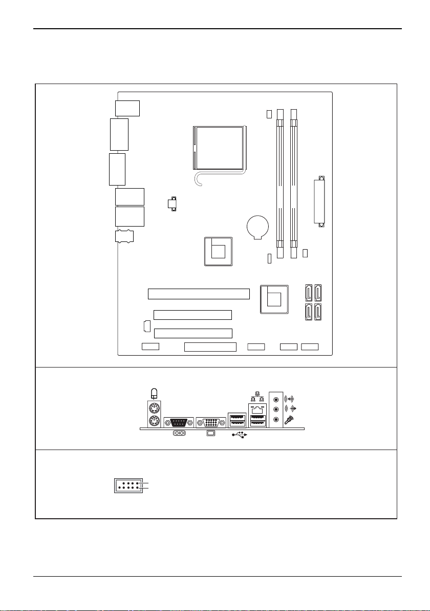
Overview Mainboard D2414
Mouse /
Keyboard
COM
port
VGA
port
Socket AM2
CPUFAN 1
External connectors rear
USB ports
LAN Jack /
USB ports
Line In /
Line out /
mic
JSP1
JAUD1
USB dual channel
1
2
PWR 1
AMD
780V
PCIE16 X1
PCI1
PCI2
FDD1
1 = VCC AUX
2 = VCC AUX
3 = Data negative Port X
4 = Data negative Port Y
5 =
Data positive Port X
DIMM 1
DIMM 2
BATT +
JBAT1
AMD
SB700
JUSB1 JFB1 JUSB2
6 = Data positive Port Y
7 =
GND
8 = GND
9 = Key
10 = Not connected
SYSFAN 1
SATA 3
SATA 1
ATX 1
SATA 4
SATA 2
A26361-D2414-Z140-1-7619
A26361-D2414-Z120-1-7419, edition 1 1
Page 10

Overview Mainboard D2414
2 A26361-D2414-Z120-1-7419, edition 1
Page 11
Mainboard D2414
Mainboard D2414
Thank you for choosing the mainboard D2414 Micro-ATX. The mainboard D2414 is design based on
AMD®780V + AMD®SB700 chipsets for optimal system efficiency. Designed to fit the advanced
AMD® Sempron / Athlon 64 X2 / Athlon 64 / Phenom processor, the mainboard D2414 delivers a
high performance and professional desktop platform solution.
Notational conventions
The meanings of the symbols and fonts used in this manual are as follows:
Indicates information which is important for your health or for preventing physical damage.
!
Indicates additional information which is required to use the system properly.
i
► Text which follows this symbol describes activities that must be performed in the order shown.
This symbol indicates that you must press the Enter key.
Text in this typeface indicates screen outputs.
Text in this bold typeface indicates the entries you make via the keyboard.
Text in italics indicates commands or menu items.
"Quotation marks" indicate names of chapters or terms.
A26361-D2414-Z120-1-7419, edition 1 3
Page 12
Mainboard D2414
Important notes
With the mainboard installed you must open the system to access the mainboard. How to dismantle
and reassemble the system is described in the operating manual accompanying the system.
Connecting cables for peripherals must be adequately shielded to avoid interference.
Information about boards
To prevent damage to the mainboard, the components and conductors on it, please take great care
when you insert or remove boards. Take great care to ensure that extension boards are slotted in
straight, without damaging components or conductors on the mainboard, or any other components,
for example EMI spring contacts.
Remove the plug from the mains outlet so that system and mainboard are totally disconnected from
the mains voltage.
Be careful with the locking mechanisms (catches, centring pins etc.) when you replace the
mainboard or components on it, for example memory modules or processors.
Never use sharp objects (screwdrivers) for leverage.
Observe the safety notes in the operating manual of your system.
!
Incorrect replacement of the lithium battery may lead to a risk of explosion.
Components can become very hot during operation. Ensure you do not touch components
when making extensions to the mainboard. There is a danger of burns!
The shipped version of this board complies with the requirements of the EEC directive
2004/108/EC "Electromagnetic compatibility" and 2006/95/EC “Low voltage directive”.
Compliance was tested in a typical PC configuration.
When installing the board, refer to the specific installation information in the manual for
the receiving device.
The warranty is invalidated if the system is damaged during the installation or replacement
of expansions. Information on which expansions you can use is available from your sales
i
outlet or the customer service centre.
Boards with electrostatic sensitive devices (ESD) are identifiable by the label shown.
When you handle boards fitted with ESDs, you must, under all circumstances,
observe the following:
● You must always discharge static build up (e.g. by touching a grounded object)
before working.
● The equipment and tools you use must be free of static charges.
● Remove the power plug from the mains supply before inserting or removing
boards containing ESDs.
● Always hold boards with ESDs by their edges.
● Never touch pins or conductors on boards fitted with ESDs.
4 A26361-D2414-Z120-1-7419, edition 1
Page 13

Mainboard D2414
Hardware Specifications
Processors
● Supports AMD® Sempron / Athlon 64 X2 /
Athlon 64 / Phenom processor
● Supports 4 pin CPU Fan Pin-Header with
Fan Speed Control
● Supports up to 6000+ and higher CPU
Supported FSB
● Hyper Transport support speed up to
3.0GHz
Chipset
● North Bridge: AMD® 780V chipset
● South Bridge: AMD® SB700 chipset
Memory Support
● DDR2 533/667/800 unbuffered SDRAM
(240pin / 1.8V)
● 2 DDR2 DIMMs (4GB Max)
LAN
● Supports LAN 10/100/1000 Fast Ethernet
by RTL8111C
SATA
● 4 SATA II ports by SB700
● Supports 4 SATA II devices
● Supports storage and data transfers at up
to 300MB/s
Floppy
● 1 floppy port
● Supports 1 FDD with 360KB, 720KB,
1.2MB, 1.44MB and 2.88MB
Connectors
● Back panel
– 1 PS/2 mouse port
– 1 PS/2 keyboard port
– 1 serial port (COM1)
– 1 VGA port
– 4 USB 2.0 Ports
– 1 LAN jack
– 3 flexible audio jacks
● On-Board Pinheaders / Connectors
– 2 USB 2.0 pinheaders
– 1 Front Panel Audio pinheader
Slots
● 1 PCI Express x16 slot
● 2 PCI slots
Audio
● Chip integrated by Realtek® ALC888
● Flexible audio jacks
● Compliant with High Definition Audio 5.1
A26361-D2414-Z120-1-7419, edition 1 5
Form Factor
● µATX (24.4 cm x 21.5 cm)
Mounting
● 6 mounting holes
Page 14

Mainboard D2414
Hardware Setup
This chapter tells you how to install the CPU, memory modules, and expansion cards, as well as how
to setup the jumpers on the mainboard. It also provides the instructions on connecting the peripheral
devices, such as the mouse, keyboard, etc. While doing the installation, be careful in holding the
components and follow the installation procedures.
CPU Installation Procedures for Socket AM2+
► Turn off the power and unplug the
1
2
powercord before installing the CPU.
► Pull the lever sideways away from the
socket (1). Make sure to raise the lever up
to a 90-degree angle.
► Look for the gold arrow of the CPU. The
gold arrow should point as shown in the
picture. The CPU can only fit in the correct
orientation (2).
If the CPU is correctly installed, the pins should
be completely embedded into the socket and can
not be seen. Note that any violation of the correct
installation procedures may cause permanent
damages to your mainboard.
3
3
Overheating will seriously damage the CPU and system. Always make sure the cooling fan
can work properly to protect the CPU from overheating.
!
Make sure that you apply an even layer of heat sink paste (or thermal tape) between the
CPU and the heatsink to enhance heat dissipation.
While replacing the CPU, always turn off the ATX power supply or unplug the power
supply power cord from the grounded outlet first to ensure the safety of CPU.
6 A26361-D2414-Z120-1-7419, edition 1
► Press the CPU down firmly into the socket
and close the lever. As the CPU is likely to
move while the lever is being closed,
always close the lever with your fingers
pressing tightly on top of the CPU to make
sure the CPU is properly and completely
embedded into the socket.
Page 15

Mainboard D2414
Installing AMD Socket AM2+ CPU Cooler Set
When you are installing the CPU, make sure the CPU has a heat sink and a cooling fan attached on
the top to prevent overheating. If you do not have the heat sink and cooling fan, contact your dealer
to purchase and install them before turning on the computer.
Mainboard photos shown in this section are for demonstration of the cooler installation for
Socket AM2 CPUs only. The appearance of your mainboard may vary depending on the
i
model you purchase.
► Position the cooling set onto the retention
mechanism. Hook one end of the clip to
hook first (1).
► Then press down the other end of the clip
to fasten the cooling set on the top of the
retention mechanism. Locate the Fix Lever
and lift up it.
► Fasten down the lever.
► Attach the CPU Fan cable to the CPU fan
connector on the mainboard.
A26361-D2414-Z120-1-7419, edition 1 7
While disconnecting the Safety Hook from the fixed bolt, it is necessary to keep an eye on
your fingers, because once the Safety Hook is disconnected from the fixed bolt, the fixed
!
lever will spring back instantly.
Page 16

Mainboard D2414
Memory Installation Procedure
When installing memory modules, make sure the modules align properly with the memory socket.
There should be keys (small indents) on your memory modules that fit according to the keys in the
memory socket. DDR modules and sockets have only one key, which is slightly near the center of
the module/socket. The method of installing memory modules is detailed in the following diagrams.
Installing a memory module
2
1
2
► Push the holders on each side of the memory slot outwards.
► Insert the memory module into the location (1).
► At the same time flip the lateral holders upwards until the memory module snaps in place (2).
8 A26361-D2414-Z120-1-7419, edition 1
Page 17

Mainboard D2414
Removing a memory module
1
► Push the clips on the right and left of the memory slot outward (1).
► Pull the memory module out of the memory slot (2).
When installing memory, a module may require a considerable amount of force to seat
properly, although this is very rare. To avoid bending and damaging your motherboard,
i
place it on its anti-static bag and onto a flat surface, and then proceed with memory
installation.
You must unplug the power connector to the motherboard before performing system
hardware changes, to avoid damaging the board or expansion device.
!
2
1
A26361-D2414-Z120-1-7419, edition 1 9
Page 18

Mainboard D2414
#
V
ATX 24-Pin Power Connector: ATX1
This connector allows you to connect an ATX 24-pin power supply.
+3.3V
+12V
+12V
5VSB
PWR OK
GND
+5V
GND
+5V
GND
+3.3V
+3.3V
GND
► To connect the ATX 24-pin power supply, make sure the plug of the
+5V
+5V
+5V
Res
GND
GND
GND
PS-ON
GND
-12V
+3.3V
power supply is inserted in the proper orientation and the pins are
aligned. Then push down the power supply firmly into the connector.
You may use the 20-pin ATX power supply as you like. If you like to use the 20pin ATX power supply, please plug your power supply along with pin 1 & pin 13
(refer to the image at the left hand).
ATX 12V Power Connector: PWR1
This 12V power connector is used to provide power to the CPU.
+12V
GNDGND
+12
Make sure that all the connectors are connected to proper ATX power supplies to ensure
stable operation of the mainboard.
!
Power supply of 350 watts (and above) is highly recommended for system stability. ATX
12V power connection should be greater than 18A.
Floppy Disk Drive Connector: FDD1
This connector supports 360KB, 720KB, 1.2MB, 1.44MB or 2.88MB floppy
disk drive.
Serial ATA Connector: SATA1 ~ 4
This connector is a high-speed Serial ATA interface port. Each connector can
connect to one Serial ATA device.
Do not fold the Serial ATA cable into 90-degree angle. Otherwise,data loss may occur
during transmission.
i
10 A26361-D2414-Z120-1-7419, edition 1
Page 19

Mainboard D2414
r
US
S
Fan Power Connectors: CPUFAN1, SYSFAN1
Sensor
+12V
GND
Control
Senso
+12V
GND
The fan power connectors support system cooling fan with +12V. When
connecting the wire to the connectors, always note that the red wire is the
positive and should be connected to the +12V; the black Sensor wire is Ground
and should be connected to GND. If the mainboard has a System Hardware
Monitor chipset on-board, you must use a specially designed fan with speed
sensor to take advantage of the CPU fan control.
Front Panel Audio Connector: JAUD1
Front to Sense
(9)Line-out_L
(10)Line_JD
Line-out_R
MIC_R
VCC5
NC
MIC2_JD
MIC_L(1)
GND(2)
This connector allows you to connect the front panel audio
and is compliant with Intel® Front Panel I/O Connectivity
Design Guide.
Front USB Connector: JUSB1/2
(9)Key,no pin
(10)N.C.
GND
GND
USB0+
B1+
USB0-
USB1-
VCC(1)
VCC(2)
This connector, compliant with Intel® I/O Connectivity
Design Guide, is ideal for connecting high-speed USB
interface peripherals such as USB HDD, digital cameras,
MP3 players, printers, modems and the like.
Front Panel Connectors: JFP1
HDD
Reset
LED
Switch
10 2
Power
+---
witch
+
Power
+
LED
19
These connectors are for electrical connection to the front
panel switches and LEDs. The JFP1 is compliant with
Intel® Front Panel I/O Connectivity Design Guide.
A26361-D2414-Z120-1-7419, edition 1 11
Page 20

Mainboard D2414
Clear CMOS Jumper: JBAT1
There is a CMOS RAM onboard that has a power supply from an
3
2
1
Keep Data Clear Data
i
33
22
11
You can clear CMOS by shorting 2-3 pin while the system is off. Then return to 1-2 pin
position. Avoid clearing the CMOS while the system is on; it will damage the mainboard.
external battery to keep the data of system configuration. With the
CMOS RAM, the system can automatically boot OS every time it is
turned on. If you want to clear the system configuration, set the jumper
to clear data.
PCI (Peripheral Component Interconnect) Express Slot
The PCI Express slot supports the PCI Express interface expansion card e.g. a graphic card.
The PCI Express x 16 slot supports up to 4.0 GB/s transfer rate.
PCI (Peripheral Component Interconnect) Slot
The PCI slot supports LAN card, SCSI card, USB card, and other add-on cards that comply with PCI
specifications.
When adding or removing expansion cards, make sure that you unplug the power supply
first. Meanwhile, read the documentation for the expansion card to configure any
i
necessary hardware or software settings for the expansion card, such as jumpers,
switches or BIOS configuration.
LAN Link/Activity LED Scheme
10/100/1000 Mbps LAN Link/Activity LED Scheme
RIGHTLEFT
10 Mbps Active Blinking Yellow Off
100 Mbps Active Blinking Yellow Green
1000 Mbps Active Blinking Yellow Red
Left LED Right LED
12 A26361-D2414-Z120-1-7419, edition 1
Page 21

BIOS Update
BIOS Update
When should a BIOS update be carried out?
Fujitsu Siemens Computers makes new BIOS versions available to ensure compatibility with new
operating systems, new software or new hardware. In addition, new BIOS functions can also be
integrated.
A BIOS update should always also be performed when a problem exists that cannot be solved with
new drivers or new software.
Where can I obtain BIOS updates?
You will find the relevant installation files for diskette, USB memory stick or DeskFlash on the
Internet under "www.fujitsu-siemens.com/mainboards".
Optional BIOS update under DOS with bootable BIOS update floppy disk – brief description
► Download the update file from our website to your PC.
► Insert an empty diskette (1.44 MByte).
► Run the update file (e.g. 2414103.EXE).
A bootable update diskette is created. Leave this diskette in the drive.
► Restart the PC.
► Follow the instructions on screen.
Alternatively, the BIOS can be updated under DOS using a bootable USB memory stick.
i
A26361-D2414-Z120-1-7419, edition 1 13
Page 22

BIOS Update
14 A26361-D2414-Z120-1-7419, edition 1
Page 23

Inhalt
Übersicht über das Mainboard D2414 .............................................................................................. 1
Mainboard D2414................................................................................................................................ 3
Handbuchkonventionen........................................................................................................................ 3
Wichtige Hinweise ................................................................................................................................ 4
Allgemeine Informationen im Zusammenhang mit Boards........................................................... 5
Hardware-Spezifikationen .................................................................................................................... 6
Hardware-Setup ................................................................................................................................... 7
Installation von AMD AM2+-Sockel + CPU-Lüfterkomponenten .......................................................... 8
Vorgehen bei der Speicherinstallation.................................................................................................. 9
24-poliger ATX-Netzanschluss: ATX1................................................................................................ 11
12V ATX-Netzanschluss: PWR1 ........................................................................................................ 11
Floppy-Laufwerkanschluss: FDD1...................................................................................................... 11
Serieller ATA-Anschluss: SATA1 ~ 4 ................................................................................................. 11
Lüfteranschlüsse: CPUFAN1, SYSFAN1 ........................................................................................... 12
Frontblenden-Audio-Anschluss: JAUD1............................................................................................. 12
Vorderer USB-Anschluss: JUSB1/2 ................................................................................................... 12
Frontblenden-Anschluss: JFP1 .......................................................................................................... 12
Clear CMOS Jumper: JBAT1 ............................................................................................................. 13
PCI (Peripheral Component Interconnect) Express Steckplatz.......................................................... 13
PCI (Peripheral Component Interconnect) Steckplatz........................................................................ 13
LAN-Verbindung/-Aktivität – LED-Schema......................................................................................... 13
BIOS-Update ..................................................................................................................................... 14
Optionales BIOS-Update unter DOS mit boot-fähiger BIOS-Update-Floppy-Diskette –
Kurzbeschreibung.......................................................................................................................
14
A26361-D2414-Z120-1-7419, Ausgabe 1
Page 24

Inhalt
A26361-D2414-Z120-1-7419, Ausgabe 1
Page 25

Übersicht über das Mainboard D2414
Mouse /
Keyboard
COM
port
VGA
port
Socket AM2
CPUFAN 1
External connectors rear
USB ports
LAN Jack /
USB ports
Line In /
Line out /
mic
JSP1
JAUD1
USB dual channel
1
2
PWR 1
AMD
780V
PCIE16 X1
PCI1
PCI2
FDD1
1 = VCC AUX
2 = VCC AUX
3 = Data negative Port X
4 = Data negative Port Y
5 =
Data positive Port X
DIMM 1
DIMM 2
BATT +
JBAT1
AMD
SB700
JUSB1 JFB1 JUSB2
6 = Data positive Port Y
7 =
GND
8 = GND
9 = Key
10 = Not connected
SYSFAN 1
SATA 3
SATA 1
ATX 1
SATA 4
SATA 2
A26361-D2414-Z140-1-7619
A26361-D2414-Z120-1-7419, Ausgabe 1 1
Page 26

Übersicht über das Mainboard D2414
2 A26361-D2414-Z120-1-7419, Ausgabe 1
Page 27

Mainboard D2414
Mainboard D2414
Vielen Dank, dass Sie sich für das Mainboard D2414 Micro-ATX entschieden haben. Das Design
des Mainboards D2414 basiert auf den AMD®780V + AMD®SB700-Chipsätzen und bietet damit
optimale Systemeffizienz. Das Mainboard D2414 wurde für die Nutzung der erweiterten AMD®
Sempron / Athlon 64 X2 / Athlon 64 / Phenom Prozessoren konzipiert und bietet eine professionelle
High-Performanc-Desktop-Plattformlösung.
Handbuchkonventionen
Bedeutung der in diesem Handbuch verwendeten Symbole und Schriftarten:
kennzeichnet Hinweise, deren Nichtbeachtung die Gesundheit gefährdet oder zu
!
Sachschäden führt.
kennzeichnet zusätzliche Informationen und Tipps für den sachgerechten Umgang mit
i
dem System.
► Mit diesem Symbol folgenden Texten werden Aktivitäten beschrieben, die in der aufgelisteten
Reihenfolge durchgeführt werden müssen.
Dieses Symbol signalisiert, dass die Eingabetaste gedrückt werden muss.
Text in dieser Schriftart kennzeichnet Bildschirmausgaben.
Text in dieser Fettschrift steht für Eingaben, die über die Tastatur erfolgen.
Text in Kursivschrift kennzeichnet Befehle oder Menüpunkte.
Mit "Anführungszeichen" werden Kapitelnamen oder Begriffe gekennzeichnet.
A26361-D2414-Z120-1-7419, Ausgabe 1 3
Page 28

Mainboard D2414
Wichtige Hinweise
Zum Zugriff auf das installierte Mainboard muss das System geöffnet werden. Wie das System
auseinandergebaut und wieder zusammengesetzt wird, ist im begleitenden Bedienerhandbuch
beschrieben.
Zur Vermeidung von Interferenzen müssen die Verbindungskabel für die Peripherie entsprechend
abgeschirmt sein.
Bitte beachten Sie die Sicherheitshinweise aus dem Bedienerhandbuch zu Ihrem System.
!
Ein unsachgemäßer Austausch des Lithium-Akkus birgt ein Explosionsrisiko.
Die Komponenten können während des Betriebs sehr heiß werden. Vermeiden Sie bei
Erweiterungen des Mainboards eine Berührung der Komponenten. Es besteht
Verbrennungsgefahr!
Das Board ist bei Auslieferung mit folgenden EG-Richtlinien konform: 2004/108/EG
"Richtlinie des Europäischen Parlaments und des Rates zur Angleichung der
Rechtsvorschriften der Mitgliedstaaten über die elektromagnetische Verträglichkeit" und
2006/95/EG "Richtlinie des Europäischen Parlaments und des Rates zur Angleichung
der Rechtsvorschriften der Mitgliedstaaten betreffend elektrische Betriebsmittel zur
Verwendung innerhalb bestimmter Spannungsgrenzen".
Die Konformität wurde in einer typischen PC-Konfiguration getestet und nachgewiesen.
Beachten Sie bei der Installation des Boards die spezifischen Anweisungen aus dem
Handbuch für das Empfangsgerät.
Bei Schäden am System durch unsachgemäßes Vorgehen bei der Installation oder beim
Austauschen von Erweiterungen verliert die Garantie ihre Gültigkeit. Informationen zu
i
zulässigen Erweiterungen erhalten Sie über Ihre Verkaufsniederlassung oder über das
Kundenservicezentrum.
4 A26361-D2414-Z120-1-7419, Ausgabe 1
Page 29

Mainboard D2414
Allgemeine Informationen im Zusammenhang mit Boards
Zur Vermeidung von Schäden am Mainboard und der darauf installierten Komponenten und
Leiterplatten ist beim Einfügen und Entfernen von Boards äußerste Sorgfalt angebracht. Achten Sie
besonders darauf, dass Erweiterungs-Boards gerade in die Steckplätze eingesetzt werden, damit
Komponenten oder Leiterplatten auf dem Mainboard und auch andere Komponenten (wie z. B. EMIFederkontakte) nicht beschädigt werden.
Ziehen Sie den Stecker aus der Hauptsteckdose, so dass System und Mainboard vollständig von der
Hauptstromversorgung getrennt sind.
Achten Sie beim Austausch des Mainboards oder darauf installierter Komponenten (z. B.
Speichermodule oder Prozessoren) besonders auf die Verriegelungsmechanismen (Arretierungen,
Zentrierungsstifte).
Verwenden Sie zum Aushebeln niemals scharfkantige Objekte (Schraubendreher).
Boards mit elektrostatisch empfindlichen Geräten (Electrostatic Sensitive Devices
(ESD)) sind durch ein Etikett entsprechend gekennzeichnet.
Bitte beachten Sie beim Umgang mit Boards, auf denen sich solche ESDs befinden,
unbedingt Folgendes:
● Vor der Arbeit müssen Sie immer für eine statische Entladung (z. B. durch
Berühren eines geerdeten Objekts) sorgen.
● Die verwendeten Geräte und Werkzeuge dürfen nicht statisch aufgeladen sein.
● Ziehen Sie den Stecker aus der Stromhauptversorgung, bevor Sie Boards, die
ESDs enthalten, einfügen oder entfernen.
● Fassen Sie Boards mit ESDs stets an den Rändern an.
● Vermeiden Sie bei mit ESDs ausgestatteten Boards unbedingt die Berührung
von Kontakten und Leitern.
A26361-D2414-Z120-1-7419, Ausgabe 1 5
Page 30

Mainboard D2414
Hardware-Spezifikationen
Prozessoren
● Unterstützt AMD® Sempron / Athlon 64 X2
/ Athlon 64 / Phenom Prozessoren
● Unterstützung für 4-poligen CPU Fan Pin-
Header mit Fan Speed Control
● Unterstützt 6000+ und höhere CPUs
Unterstützter FSB
● Hyper Transport Support-Geschwindigkeit
bis zu 3,0 GHz
Chipsatz
● North Bridge: AMD® 780V-Chipsatz
● South Bridge: AMD® SB700-Chipsatz
Speicher-Support
● Ungepuffertes SDRAM DDR2
533/667/800 (240-polig / 1,8 V)
● 2 DDR2 DIMMs (4 GB max.)
LAN
● Unterstützt LAN 10/100/1000 Fast
Ethernet durch RTL8111C
SATA
● 4 SATA II Ports durch SB700
● Unterstützt 4 SATA II-Geräte
● Unterstützt Storage- und
Datenübertragungen von bis zu 300 MB/s
Floppy
● 1 Floppy-Port
● Unterstützt 1 FDD mit 360 KB, 720 KB, 1,2
MB, 1, 44 MB und 2,88 MB
Anschlüsse
● Hintere Blende
– 1 PS/2-Maus-Port
– 1 PS/2-Tastatur-Port
– 1 serieller Port (COM1)
– 1 VGA-Port
– 4 USB 2.0-Ports
– 1 LAN-Buchse
– 3 flexible Audio-Buchsen
● On-Board Pinheader / Anschlüsse
– 2 USB 2.0 Pinheader
– 1 Frontblenden Audio Pinheader
Steckplätze
● 1 PCI Express x16 Steckplatz
● 2 PCI-Steckplätze
Audio
● Integrierter Chip durch Realtek® ALC888
● Flexible Audio-Buchsen
● Kompatibel mit High Definition Audio 5.1
6 A26361-D2414-Z120-1-7419, Ausgabe 1
Formfaktor
● µATX (24,4 cm x 21,5 cm)
Montage
● 6 Montagelöcher
Page 31

Mainboard D2414
Hardware-Setup
In diesem Kapitel wird beschrieben, wie Sie die CPU, Speichermodule und Erweiterungskarten
installieren und wie Sie die Jumper auf dem Mainboard einstellen. Zudem erhalten Sie Anleitungen
zum Verbinden der Peripheriegeräte, wie z. B. Maus, Tastatur usw. Üben Sie bei der Installation
besondere Sorgfalt beim Anfassen und Halten der Komponenten und folgen Sie den
Installationsanleitungen.
CPU Installationsverfahren für AM2+-Sockel
► Schalten Sie vor der Installation der CPU
1
2
3
3
Eine Überhitzung führt zu schweren Schäden an CPU und System. Sorgen Sie dafür, dass
der Lüfter zum Schutz der CPU vor Überhitzung ordnungsgemäß arbeiten kann.
!
Tragen Sie für eine verbesserte Ableitung eine gleichmäßige Schicht wärmeleitender
Paste (oder nutzen Sie ein thermales Band) zwischen CPU und Wärmeableiter auf.
Schalten Sie vor dem Austausch der CPU stets die ATX-Stromversorgung aus oder
ziehen Sie das Netzkabel aus der geerdeten Steckdose, um die Sicherheit der CPU zu
gewährleisten.
das Gerät ab und trennen Sie das
Netzkabel.
► Ziehen Sie die seitlichen Hebel fort vom
Sockel (1). Bringen Sie den Hebel in einen
90-Grad-Winkel.
► Lokalisieren Sie das goldene Pfeilsymbol
der CPU. Der goldene Pfeil sollte wie in der
Abbildung gezeigt ausgerichtet sein. Die
CPU kann nur in der korrekten Ausrichtung
eingepasst werden (2).
Bei korrekter Installation der CPU müssen die
Pole komplett im Sockel integriert sein, so dass
sie nicht mehr sichtbar sind. Hinweis: eine
Missachtung des korrekten
Installationsverfahrens kann Ihr Mainboard
unwiderruflich beschädigen.
► Drücken Sie die CPU fest in den Sockel
und schließen Sie den Hebel. Da die CPU
beim Schließen des Hebels dazu neigt, sich
zu bewegen, drücken Sie bei diesem
Vorgang fest mit den Fingern oben auf die
CPU, um sicherzustellen, dass sie
ordnungsgemäß und vollständig in den
Sockel integriert wurde.
A26361-D2414-Z120-1-7419, Ausgabe 1 7
Page 32

Mainboard D2414
Installation von AMD AM2+-Sockel + CPULüfterkomponenten
Sorgen Sie bei der Installation der CPU dafür, dass als Überhitzungsschutz oben auf der CPU Lüfter
und Wärmeableiter angebracht sind. Bei Bedarf können Sie Wärmeableiter und Lüfter über Ihren
Händler beziehen. Die Installation der Komponenten muss vor dem Anschalten des Computers
erfolgen.
Die in diesem Abschnitt gezeigten Abbildungen des Mainboards illustrieren lediglich die
Installation für AM2-Sockel CPUs. Je nach erworbenem Modell kann das Erscheinungsbild
i
Ihres Mainbords von den Illustrationen abweichen.
► Positionieren Sie die Kühlkomponenten auf
dem Rückhaltemechanismus. Haken Sie
zuerst ein Ende der Klammer ein (1).
► Drücken Sie anschließend das andere
Ende der Klammer herunter, um die
Kühlkomponenten oben auf dem
Rückhaltemechanismus zu befestigen.
Ziehen Sie den Befestigungshebel nach
oben.
► Befestigen Sie den Hebel, indem Sie ihn
nach unten drücken.
► Verbinden Sie das CPU-Lüfterkabel mit
dem CPU-Lüfteranschluss auf dem
Mainboard.
8 A26361-D2414-Z120-1-7419, Ausgabe 1
Achten Sie beim Lösen des Sicherheitshakens vom Arretierungsbolzen auf Ihre Finger, da
der Arretierungshebel dabei sofort zurückspringt.
!
Page 33

Mainboard D2414
Vorgehen bei der Speicherinstallation
Bei der Installation von Speichermodulen müssen Sie darauf achten, dass die Module korrekt am
Speichersockel ausgerichtet sind. Auf den Speichermodulen befinden sich kleine Kerben, die zu den
Kerben im Speichersockel passen. DDR-Module verfügen nur über eine Kerbe, die sich unmittelbar
neben dem Mittelpunkt des Moduls/Sockels befindet. Die Installationsmethode für Speichermodule
wird detailliert in den folgenden Diagrammen illustriert.
Installieren eines Speichermoduls
2
1
2
► Drücken Sie die Halterungen auf beiden Seiten des Speichersteckplatzes nach außen.
► Das Speichermodul in Position (1) einfügen.
► Gleichzeitig die Seitenhalterungen nach oben schnippen, bis das Speichermodul in der
Position (2) einrastet.
A26361-D2414-Z120-1-7419, Ausgabe 1 9
Page 34

Mainboard D2414
Entfernen eines Speichermoduls
1
► Die Klammern rechts und links am Speichersteckplatz nach außen drücken (1).
► Das Speichermodul aus dem Speichersteckplatz (2) ziehen.
Mitunter kann schwierig sein, ein Modul in die korrekte Position zu bringen. Dies ist jedoch
nur äußerst selten der Fall. Setzen Sie das Motherboard auf seine antistatische
i
Schutzhülle und auf eine ebene Oberfläche, um Schäden und Verbiegungen vorzubeugen.
Fahren Sie dann mit der Speicherinstallation fort.
Zur Vermeidung von Schäden am Motherboard oder dem Erweiterungsgerät müssen Sie
das Motherboard vor der Durchführung von Systemänderungen stets von der
!
Stromversorgung trennen.
2
1
10 A26361-D2414-Z120-1-7419, Ausgabe 1
Page 35

Mainboard D2414
#
V
24-poliger ATX-Netzanschluss: ATX1
An diesen Anschluss können Sie ein 24-poliges ATX-Netzteil anschließen.
+3.3V
+12V
+12V
5VSB
PWR OK
GND
+5V
GND
+5V
GND
+3.3V
+3.3V
GND
+5V
► Stellen Sie dafür sicher, dass der Stecker des Netzteils korrekt eingesetzt
+5V
+5V
Res
GND
GND
GND
PS-ON
GND
-12V
+3.3V
ist und dass die Pole ordnungsgemäß ausgerichtet sind. Drücken Sie die
Komponente dann fest in den Anschluss.
Alternativ können Sie das 20-polige ATX-Netzteil nutzen. Nutzen Sie in diesem
Fall Pol 1 und Pol 13 (siehe linke Seite der Abbildung).
12V ATX-Netzanschluss: PWR1
Dieser 12 V-Netzanschluss dient zur Stromversorgung der CPU.
+12V
GNDGND
+12
Sorgen Sie dafür, dass alle Anschlüsse mit den korrekten ATX-Netzteilen verbunden sind,
um einen stabilen Betrieb des Mainboards zu gewährleisten.
!
Für die Systemstabilität wird ein Netzteil mit 350 Watt (und höher) dringend empfohlen.
Der 12 V ATX-Stromversorgung sollte höher als 18 A sein.
Floppy-Laufwerkanschluss: FDD1
Dieser Anschluss bietet Unterstützung für 360 KB-, 720 KB-, 1,2 MB-, 1,44
MB- oder 2,88 MB-Floppy-Laufwerke.
Serieller ATA-Anschluss: SATA1 ~ 4
Bei diesem Anschluss handelt es sich um einen seriellen Highspeed ATASchnittstellen-Port. Jeder Anschluss kann mit einem seriellen ATA-Gerät
verbunden werden.
Vermeiden Sie, das serielle ATA-Kabel in einem 90-Grad-Winkel zu knicken. Andernfalls
kann es während der Übertragung zu Datenverlusten kommen.
i
A26361-D2414-Z120-1-7419, Ausgabe 1 11
Page 36

Mainboard D2414
r
US
S
Lüfteranschlüsse: CPUFAN1, SYSFAN1
Sensor
+12V
GND
Control
Senso
+12V
GND
Die Lüfteranschlüsse unterstützen 12 V-Lüfter für die Systemkühlung. Wenn
Sie die Kabel mit den Anschlüssen verbinden, achten Sie auf Folgendes: das
rote Kabel ist das positive, das mit dem +12 V-Anschluss verbunden werden
muss, das schwarze Sensorkabel muss zur Erdung mit dem Anschluss GND
verbunden werden. Wenn auf dem Mainboard ein System Hardware MonitorChipsatz vorhanden ist, müssen Sie einen speziell entwickelten Lüfter mit
Geschwindigkeitssensor einsetzen, damit Sie die Vorteile der CPULüfterkontrolle nutzen können.
Frontblenden-Audio-Anschluss: JAUD1
Front to Sense
(9)Line-out_L
(10)Line_JD
Line-out_R
MIC_R
VCC5
NC
MIC2_JD
MIC_L(1)
GND(2)
Dieser Anschluss dient zur Verbindung der
Audiokomponenten an der Frontblende und ist kompatibel
mit dem Intel® Front Panel I/O Connectivity Design Guide.
Vorderer USB-Anschluss: JUSB1/2
(9)Key,no pin
(10)N.C.
GND
GND
USB0+
B1+
USB0-
USB1-
VCC(1)
VCC(2)
Dieser, mit dem Intel® I/O Connectivity Design Guide
kompatible Anschluss eignet sich ideal für die Verbindung
mit USB-Schnittstellengeräten, wie z. B. USB HDD,
Digitalkameras, MP3-Player, Drucker, Modems etc.
Frontblenden-Anschluss: JFP1
HDD
Reset
LED
Switch
10 2
Power
+---
witch
+
Power
LED
+
19
12 A26361-D2414-Z120-1-7419, Ausgabe 1
Diese Anschlüsse bieten die elektrische Verbindung zu
den Frontblenden-Schaltern und -LEDs. Der JFP1Anschluss ist kompatibel mit dem Intel® Front Panel I/O
Connectivity Design Guide.
Page 37

Mainboard D2414
a
Clear CMOS Jumper: JBAT1
Das Onboard-CMOS RAM wird über ein externes Akku mit Strom
3
2
1
Keep Data Clear Dat
i
33
22
11
Sie können das CMOS löschen, indem Sie bei ausgeschaltetem System die Pole 2-3
kurzschließen. Kehren Sie anschließend zur Konfiguration Pol 1-2
zurück. Auf keinen Fall sollten Sie das CMOS bei laufendem Systembetrieb löschen, da
dies zu Schäden am Mainboard führt.
versorgt, damit die Systemkonfigurationsdaten erhalten bleiben. Über
das CMOS RAM kann das System automatisch bei jedem Einschalten
das BS starten. Wenn Sie die Systemkonfiguration löschen möchten,
setzen Sie den Jumper entsprechend.
PCI (Peripheral Component Interconnect) Express Steckplatz
Der PCI Express-Steckplatz bietet Unterstützung für PCI Express-Erweiterungskarten, z. B.
Grafikkarten.
Der PCI Express x 16-Steckplatz unterstützt eine Übertragungsrate von bis zu 4,0 GB/s.
PCI (Peripheral Component Interconnect) Steckplatz
Der PCI-Steckplatz unterstützt LAN-, SCSI- und USB-Karten sowie weitere Add-On-Karten, die den
PCI-Spezifikationen entsprechen.
Trennen Sie das System vor dem Hinzufügen oder Entfernen von Erweiterungskarten
immer von der Stromversorgung. Konsultieren Sie die Dokumentation zu den
i
entsprechenden Erweiterungskarten, um die entsprechenden Hard- oder SoftwareEinstellungen zu konfigurieren (z. B. Jumper, Schalter oder BIOS-Einstellungen).
LAN-Verbindung/-Aktivität – LED-Schema
10/100/1000 Mbps LAN-Verbindung/-Aktivität – LED-Schema
RIGHTLEFT
10 Mbps Aktiv Gelb blinkend Aus
100 Mbps Aktiv Gelb blinkend Grün
1000 Mbps Aktiv Gelb blinkend Rot
Linke LED Rechte LED
A26361-D2414-Z120-1-7419, Ausgabe 1 13
Page 38

BIOS-Update
BIOS-Update
Wann sollte ein BIOS-Update durchgeführt werden?
Fujitsu Siemens Computers stellt neue BIOS-Versionen zur Verfügung, um die Kompatibilität zu
neuen Betriebssystemen, zu neuer Software oder zu neuer Hardware zu gewährleisten. Außerdem
können neue BIOS-Funktionen integriert werden.
Ein BIOS-Update sollte auch immer dann durchgeführt werden, wenn ein Problem besteht, das sich
durch neue Treiber oder neue Software nicht beheben lässt.
Wo können Sie BIOS-Updates beziehen?
Sie finden die entsprechenden Installationsdateien für Diskette, USB-Memorystick oder DeskFlash
im Internet unter "www.fujitsu-siemens.com/mainboards".
Optionales BIOS-Update unter DOS mit boot-fähiger BIOS-Update-Floppy-Diskette – Kurzbeschreibung
► Laden Sie die Update-Datei von unserer Website auf Ihren PC.
► Legen Sie eine leere Diskette (1,44 MB) in das Diskettenlaufwerk ein.
► Führen Sie die Update-Datei (z. B. 2414103.EXE) aus.
Es wird eine boot-fähige Diskette erstellt. Belassen Sie die Diskette im Laufwerk.
► Starten Sie den PC neu.
► Folgen Sie den Anweisungen auf dem Bildschirm.
Wahlweise kann das BIOS-Update unter DOS mithilfe eines boot-fähigen USBMemorysticks erfolgen.
i
14 A26361-D2414-Z120-1-7419, Ausgabe 1
 Loading...