

Page 1

Mainboard Deutsch, English, Français,
Short Description
Русский,Türkçe
Mainboard D2151
Page 2

Sie haben technische Fragen oder Probleme?
Wenden Sie sich bitte an:
• Ihren zuständigen Vertriebspartner oder Ihre Verkaufsstelle
• unsere Hotline über das Kontaktformular unter
"www.fujitsu-siemens.com/support/contact/contact.html" oder für Kunden,
Aktuelle Informationen und Updates (z. B. BIOS-Update) zu unseren Mainboards
finden Sie im Internet:
Are there any technical problems or other questions you need clarified?
Please contact:
The latest information and updates (e.g. BIOS update) on our mainboards can be found on the
Internet under:
Vous avez des questions ou des problèmes techniques ?
Adressez-vous :
Vous trouverez des informations actualisées et des mises à jour sur notre site (p. ex. BIOS-Update)
sur nos cartes mères sur notre site:
У Вас есть технические вопросы или проблемы?
Просим Вас обратиться:
Актуальную информацию и обновленные редакции программ (например, BIOS-Update)
для наших материнских плат Вы найдете в Интернете на сайте:
"http://www.fujitsu-siemens.com/mainboards"
die ein einzelnes Mainboard gekauft haben: +49(0) 180 3777 005
"http://www.fujitsu-siemens.com/mainboards"
• your sales partner or your sales outlet
• our hotline for customers who have purchased the mainboard as a single delivery unit:
+49(0) 180 3777 005
"http://www.fujitsu-siemens.com/mainboards"
• à votre partenaire de vente ou à votre point de vente
• à notre hotline au moyen du formulaire de contact que vous trouverez à l'adresse
"www.fujitsu-siemens.com/support/contact/contact.html" ou par téléphone pour les clients qui
ont acheté une carte mère séparée au : +49(0) 180 3777 005
"http://www.fujitsu-siemens.com/mainboards"
• к Вашему дилеру или в магазин, в котором Вы приобрели устройство
• к сотрудникам нашей горячей линии, указанной в контактном формуляре на сайте:
"
www.fujitsu-siemens.com/support/contact/contact.html" или же, для заказчиков,
которые купили отдельную материнскую плату, по телефону: +49(0) 180 3777 005
Sizin teknik sorularınız veya sorunlarınız mı var?
Lütfen:
• Sizin için sorumlu dağıtım partneri veya satın aldığınız yer
"www.fujitsu-siemens.com/support/contact/contact.html" adresindeki irtibat formu üzerinden
•
Hotline'ımıza başvurun veya yalnızca tek bir anakart satın alan
Anakartlarımız (Mainboards) ile ilgili oalrak aktüel bilgileri ve güncelleştirmeleri (örneğin BIOSUpdate)
internette bulabilirsiniz:
müşterilerimiz için: +49(0) 180 3777 005
"http://www.fujitsu-siemens.com/mainboards"
Page 3

Copyright © Fujitsu Siemens Computers GmbH 2006
Intel, Pentium and Celeron are registered trademarks of Intel Corporation, USA.
Microsoft, MS, MS-Dos and Windows are registered trademarks of Microsoft Corporation.
PS/2 and OS/2 Warp are registered trademarks of International Business machines, Inc.
All other trademarks referenced are trademarks of their respective owners, whose
protected rights are acknowledged.
All rights, including rights of translation, reproduction by printing, copying or similar
methodas, even of parts are reserved.
Offenders will be liable for damages.
All rights, including rights created by patent grant or registration of a utility model or
design, are reserved. Delivery subject to availability.
Right of technical modification reserved.
Page 4

Dieses Handbuch wurde erstellt von/This manuel was produced by Xerox Global Services
Herausgegeben von/Published by
Fujitsu Siemens Computers GmbH
AG 10/06
Ausgabe/Edition 1
Bestell-Nr./Order No.: A26361-D2151-Z112-1-8N19
*A26361-D2151-Z112-1-8N19*
Page 5
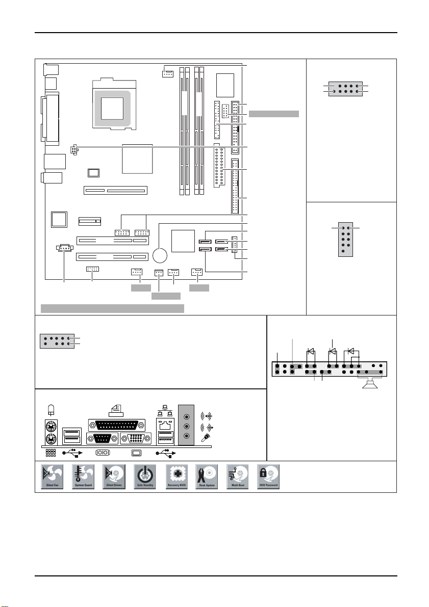
Mainboard D2151 - Internal connecto
rs and slots
PCI Express x16
PCI Express x1
PCI 1
PCI 2
Audio in
Audio front panel
Fan 4
Fan 2
Intrusion
Optionale Komponenten / Optional components
High Definition Audio (default)
Pin 2
Pin 1
1 = Micro input Left
2 = Analog GND
3 = Micro input Right
4 = Presence Detect
5 = Right Line / Headphone output
6 = Sense 1 return
7 = Jack sense Send
8 = Key
9 = Left line / Headphone output
10 = Sense 2 return
External connectors rear
Channel A
slot 1
slot 3
Fan 3
Channel B
slot 4
slot 2
Fan 1
Floppy disk drive
COM2 / Serial 2
Front panel
USB - dual channel
9
10
1 = VCC x
2 = VCC y
3 = Data negative x
4 = Data negative y
Additional power
supply +12 V
Power supply
5 = Data positive x
6 = Data positive y
7 = GND
8 = GND
9 = Key
10 = Not connected
IDE-drives 1/2
USB
Battery
Serial ATA3
Serial ATA4
Serial ATA2
Power supply
control
Serial ATA1
Serial port 2 (internal)
1 = DCD 2
2 = DSR 2
3 = SIN 2
4 = RTS 2
5 = SOUT 2
Front panel
1)
Power On/Off
Reset
1) Both jumper positions possible
2) 2pin or 3pin connector possible
Recovery inserted = The system starts
from floppy and allows a BIOS recovery
Password inserted = System- and BIOS
Password are skipped when device is
switched on
Message LED
HD-LED
Recovery Password
Pin 2Pin 1
6 = CTS 2
5 = DTR 2
8 = RI 2
9 = GND
Power On LED
Speaker
1
2
2)
1
2
A26361-D2151-Z112-1-8N19, edition 1
Page 6
Mainboard D2151
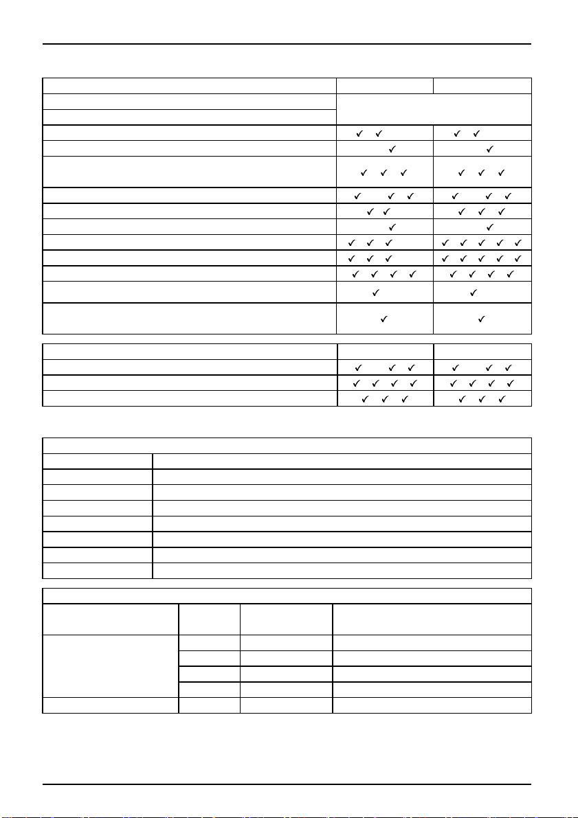
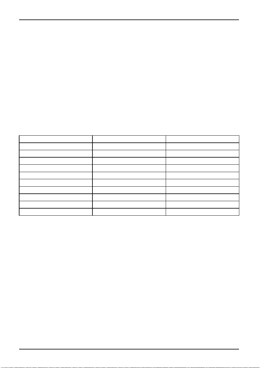
List of onboard featu re s D2151-A D2151-S
Chipset
Board size
Intel ® 945G
μATX
VGA / Audio / 6-channel / S/PDIF / /-/- / /-/Buzzer / int. Speaker Support
-/
-/
LAN1Gbit/100Mbit/10Mbit / / / /
LAN ASF / Aol / WoL / B oot /-/ / /-/ /
SATA/ATA/RAID / /- / /
FireWireTM / USB 2.0 - / -/
FAN monitored PSU** / CPU (FAN1) / FAN2 / FAN3 / FAN4
FAN controlled PSU** / CPU (FAN1) / FAN2 / FAN3 / FAN4
/ / /-/- / / / /
/ / /-/- / / / /
TEMP monitored CPU/ONB1/ONB2/HDD / / / / / /
SmartCard SystemLock (USB / serial)
/- /-
Fujitsu Siemens Computers Keybord Power Button Support
List of special o nboard features
Silent Fan/Silent Fan LT/System Guard/Silent Drives
Recovery BIOS/Desk Update/ Multi Boot/Safe Standby
Logo Boot/Intel On Screen Branding/HDD Passwort
D2151-A
D2151-S
/-/ / /-/ /
/ / / / / /
/ / / /
** not supported by standard P ower Supplies
Special Features
Silent Fan
Independent temperature related processor and fan supervision and control
System Guard View and adjust Silent Fan
Silent Drives
Noise reduction for optical and hard disk drives
Safe Standby Prevents data loss in S3 (Save-to-RAM)
Recovery BIOS
Restores a disrup ted BIOS
Desk Update Simple driver update with DU CD
Multi Boot
HDD Passwort
Comfortable boot from any boot device
Access protection for ATA5/ATAPI5 disk drives
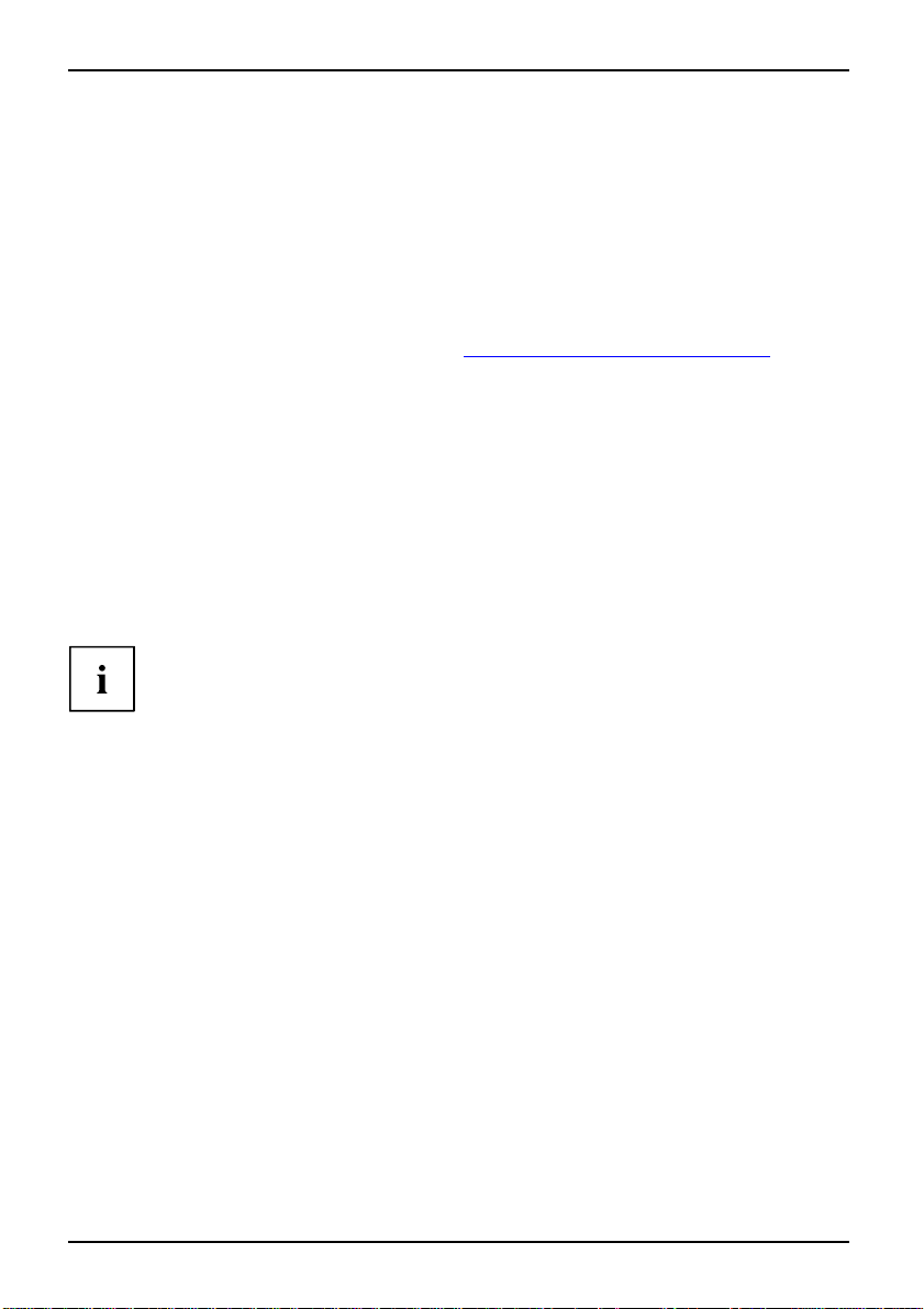
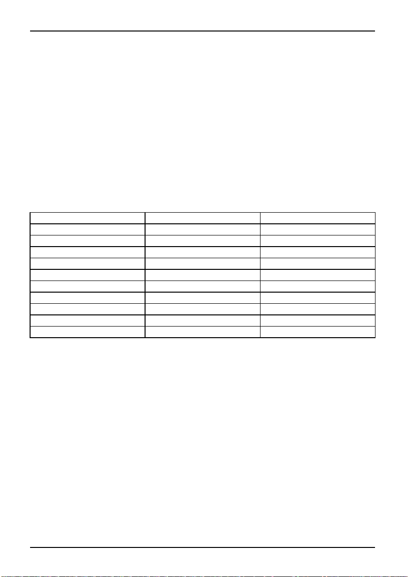
Power Supply Requirements - for onboard components (worst case)
Source
Main Power Supply
Aux. Power Supply
Vol tage
+12V
–12V
+5V +/–5% 6.0A
+3.3V
+5V
Maximal
variation
+/–5%
+/–10%
+/–5%
+/–5%
Mainboard current (Maximal)
A26361-D2151-Z112-1-8N19, edition 1
10.0 A
0.05 A
4.0 A
2.0 A
Page 7
Kurzbeschreibung des Mainboard
Kurzbeschreibung des Mainboa
Hinweise zu den Baugruppen
Beachten Sie bei Baugruppen mit EGB unbedingt Folgendes:
• Sie müssen sich statisch entladen (z. B. durch Berühren eines geerdeten
Gegenstands), bevor Sie mit Baugruppen arbeiten.
• Verwendete Geräte und Werkzeuge müssen frei von statischer Aufladung sein.
• Ziehen Sie den Netzstecker, bevor Sie Baugruppe n stecken oder ziehen.
• Fassen Sie die Baugruppen nur am Rand an.
• Berühren Sie keine Anschluss-Stifte oder Leiterbahnen auf der Baugruppe.
Eine Übersicht der Leistungsmerkmale finden Sie im Datenblatt.
Besondere Merkmale
Ihr Mainboard ist in verschiedenen Ausbaustufen erhältlich. Abhängig von der Konfiguration
Ihres Mainboards besitzt oder unterstützt das Mainboard bestimmte Merkmale.
In diesem Handbuch finden Sie die wichtigsten Eigenschaften dieses M ainboards beschrieben.
Weitere Informationen zu Mainboards finden Sie im Handbuch "Basisinformationen Mainboard"
auf der CD "User Documentation" oder "OEM Mainboard" bzw. im Internet.
rd
Anschlüsse und Steckverbinder
Die Positon der Anschlüsse und Steckverbinder Ihres Mainboards finden
Sie am Anfang des Handbuches.
Die markierten Komponenten und Steckverbinder müssen nicht auf dem Mainboard vorhanden sein.
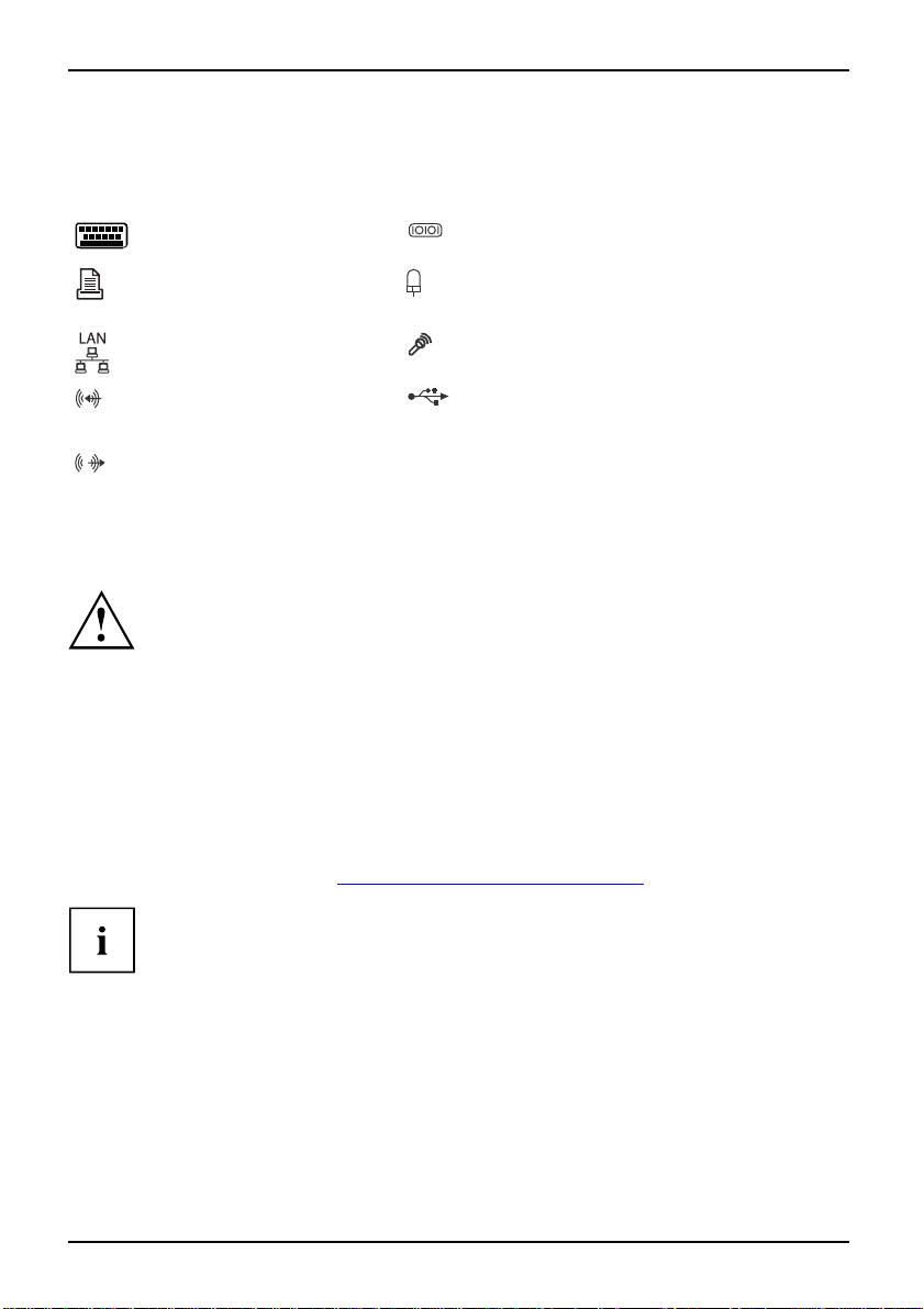
Externe Anschlüsse
Die Position der externen Ansschlüsse Ihres Mainboards finden Sie am Anfang des Handb uches.
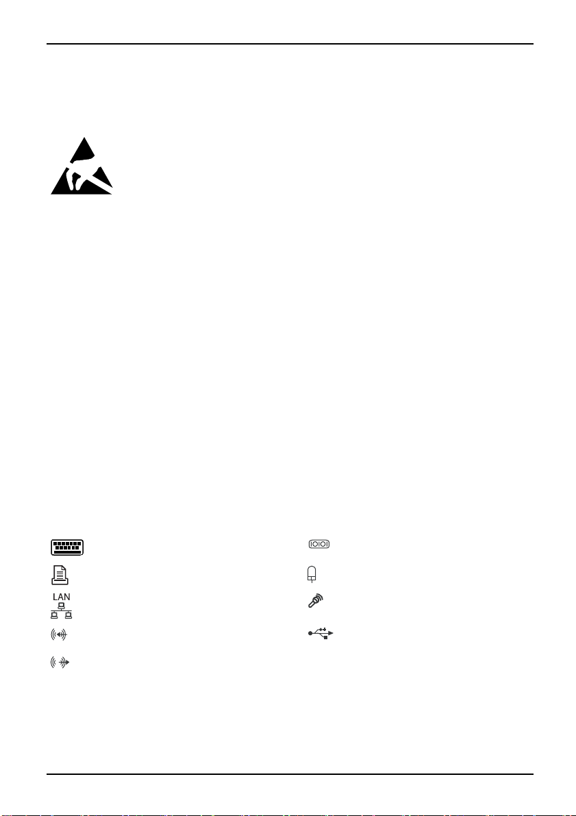
PS/2-Tastaturanschluss, violett Serielle Schnittstelle, türkis
Parallele Schnittst elle/Drucker, burgund PS/2-Mausanschluss, grün
LAN-Anschluss (RJ-45) Mikrofonanschluss, rosa
Audioeingang (Line in), hellblau USB - Universal Serial Bus,
Audioausgang (Line out), hellgrün
A26361-D2151-Z112-1-8N19, Ausgabe 1 Deutsch - 1
schwarz
Page 8
Kurzbeschreibung des Mainboard
Prozessor ein-/ausbauen (mit Kühlkörper)
Für alle hier beschriebenen Arbeiten muss Ihr System vollständig von der Netzspannung
getrennt sein! Nähere Angaben dazu finden Sie in der Betriebsanleitung Ihres Systems.
Technische Daten
• Intel Core Duo mit 800 oder 1066 MHz Front Side Bus in der Bauform LGA775 (FMB06-65W)
• Intel Pentium 4 mit 533/800/1066 MHz Front Side Bus in der Bauform
LGA775 (Mainstream FMB 05A)
• Intel Celeron D mit 533 MHz Front Side Bus in der Bauform LGA775
• Eine aktuelle Liste der von diesem Mainboard unterstützten Prozessoren finden Sie
im Internet u nter: "
Fassen Sie auf keinen Fall die Unterseite des Prozessors an. Schon leichte
Verunreinigungen wie Fett von der Haut können die Funktion des Prozessors
beeinträchtigen oder den Prozessor zerstören. Setzen Sie den Prozessor mit
großer Sorgfalt in den Steckplatz, da die F ederkontakte des Steckplatzes sehr
empfindlich sind und nicht verbogen werden dürfen.
Sind ein oder mehrere Federkontakte verbogen, setzen Sie auf keinen Fall
den Pro zessor ein, da dieser dadurch beschädigt werden könnte. Wenden
Sie sich bitte direkt an Ihren zuständigen Händler.
www.fujitsu-siemens.com/mainboards".
2 - Deutsch A26361-D2151-Z112-1-8N19, Ausgabe 1
Page 9
Vorgehensweise
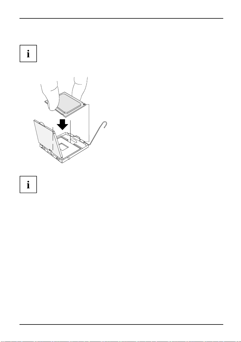
Der Steckplatz für Prozessor ist zum Schutz der F ederkontakte mit einer Schutzkappe
abgedeckt. Im Garantiefall kann das Mainboard nur mit befestigter Schutzkappe
von Fujitsu Siemens Computers zurück genommen werden!
b
b
Kurzbeschreibung des Mainboard
► Entfernen Sie den Kühlkörper.
► Drücken Sie auf den Hebel und
haken Sie ihn aus.
► Klappen Sie die Halterung nach oben.
► Halten Sie den Prozessor mit Daumen
und Zeigefinger u nd stecken Sie ihn
so in den Steckplatz (b), dass die
Markierung des Prozessors mit der
a
Markierung am Steckplatz von der Lage
her übereinstimmt (a).
► Drücken Sie den Hebel nach unten,
bis er wieder einhakt.
► Entfernen Sie die Schutzklappe und
verwahren Sie diese.
Bitte beachten S
Kühlkörperhalt
► Je nach Ausbau-Variante müssen Sie eine Schutzfolie vom Kühlkörper abziehen oder den
Kühlkörper mit Wärmeleitpaste bestreichen, bevor Sie ihn aufsetzen.
► Befestigen Sie d
oder stecken Sie
A26361-D2151-Z112-1-8N19, Ausgabe 1 Deutsch - 3
ie, dass je nach verwendetem Kühlkörper unterschiedliche
erungen auf dem Mainboard benötigt werden.
en Kühlkörper - je nach Ausführung - mit vier Schrauben
ihn in die Befestigungen.
Page 10
Kurzbeschreibung des Mainboard
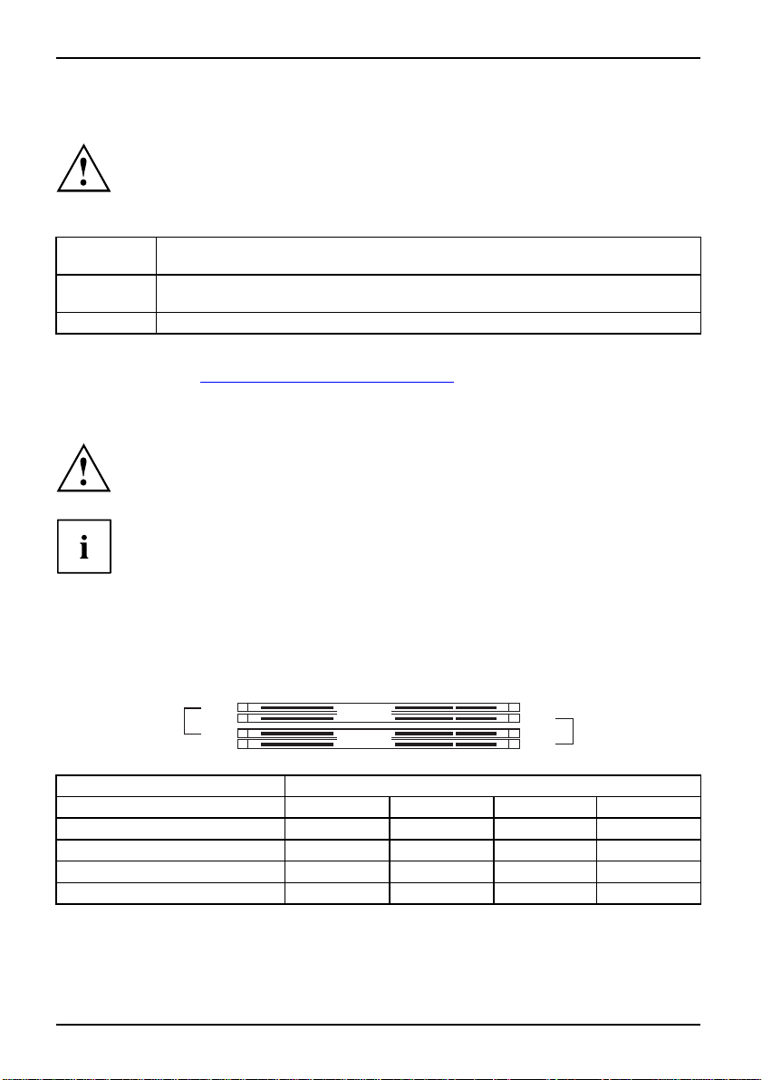
Hauptspeicher ein-/ausbauen
Für alle hier beschriebenen Arbeiten muss Ihr System vollständig von der Netzspannung
getrennt sein! Nähere Angaben dazu finden Sie in der Betriebsanleitung Ihres Systems.
Technische Daten
Technologie
Gesamtgröße 256 MBytes bis 4GByte DDR2
Modulgröße
Eine aktuelle Liste der für dieses Mainboard empfohlenen Speichermodule finden Sie
im Internet unter: "
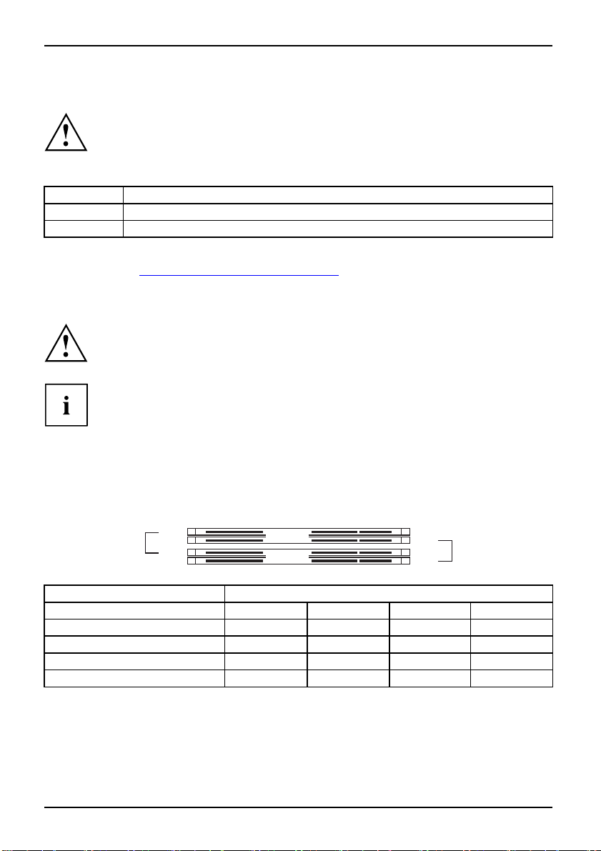
Es muss mindestens ein Speichermodul eingebaut sein. Speichermodule mit unterschiedlicher
Speicherkapazität können kombiniert werden.
DDR2 400 / 533 / 667 ungepufferte DIMM Module 240-Pin; 1,8 V; 64 Bit, ohne ECC
256, 512 oder 1024 MByte pro Modul
www.fujitsu-siemens.com/mainboards".
Es dürfen nur ungepufferte 1,8 V-Speichermodule ohne ECC verwendet werden.
DDR2-Speichermodule müssen der PC2-4200U- oder PC2-5300U- oder
PC2-6400U-Spezifikation entsprechen.
Wenn Sie mehr als ein Speichermodul verwenden, dann achten Sie darauf,
die Speicherm odule auf beide Speicherkanäle aufzuteilen. Dadurch nutzen
Sie die Performancevorteile des Dual-Channel-Mode.
Die maximale S yste mperformance ist gegeben , wenn in Channel A und
Channel B die gleiche Speichergröße verwendet wird.
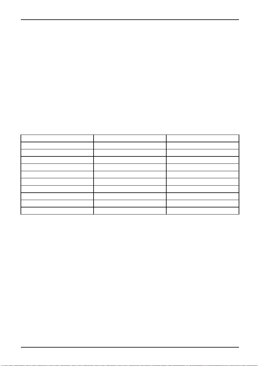
Um die Bestückung zu erleichtern, sind die Steckplätze (Slots) farbig gekennzeichnet.
Bei einer Speicherkonfiguration von 4 Gbyte kann der sichtbare und benutzbare Haupt-
speicher auf bis zu 3 Gbyte reduziert sein (abhängig von der Konfiguration des Systems).
slot 4
slot 3
Channel B
Channel A
slot 2
slot 1
Anzahl der gesteckten Speichermodule
Zu verwendender Steck
Channel A, Slot 1
Channel A, Slot 3
Channel B, Slot 2
Channel B, Slot 4
platz
1234
xxxx
xx
xxx
x
Der Ein-/Ausbau ist im Handbuch "Basisinformationen Mainboard" beschrieben.
4 - Deutsch A26361-D2151-Z112-1-8N19, Ausgabe 1
Page 11
Kurzbeschreibung des Mainboard
PCI-Bus-Interrupts - Auswahl des richtigen PCI-Steckplatzes
Umfangreiche Informationen zu diesem Abschnitt finden Sie im Handb uch
"Basisinformationen Mainboard".
Um optimale Stabilität, Performance und Kompatibilität zu erreichen, vermeiden
Sie die mehrfache Nutzung von ISA IRQs oder PCI IRQ Lines (IRQ Sharing).
Sollte IRQ Sharing nicht zu umgehen sein, so müssen alle beteiligten Geräte
und deren Treiber IRQ Sharing unterstützen.
Welche ISA IRQs den PCI IRQ Lines zugeordnet werden, wird normalerweise automatisch
vom BIOS festgelegt (siehe Beschreibung "
Monofunktionale Erweiterungskarten
PCI-/PCI-Express-Erweiterungskarten benötigen maximal einen Interrupt, der als
PCI-Interrupt INT A bezeichnet wird. Erweiterungskarten, die keinen Interrupt benötigen,
können in einen beliebigen Steckplatz eingebaut werden.
Multifunktionale Erweiterungskarten oder Erweiterungskarten mit integrierter PCI-PCI Brigde
Diese Erweiterungskarten benötigen bis z u vier PCI-Interrupts: INT A, INT B, INT C , INT D.
Wie viele und welche dieser Interrupts verwendet werden, entnehmen Sie der
mitgelieferten Dokumentation der Karte.
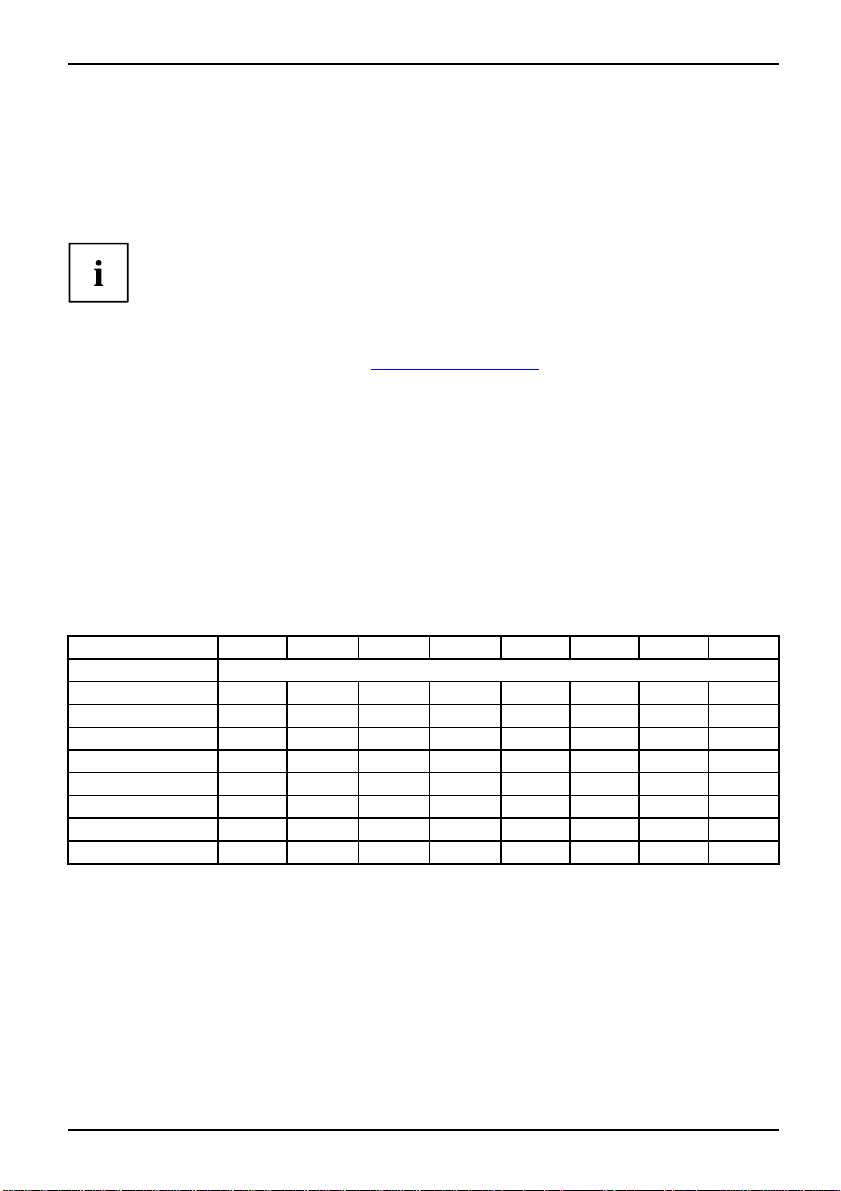
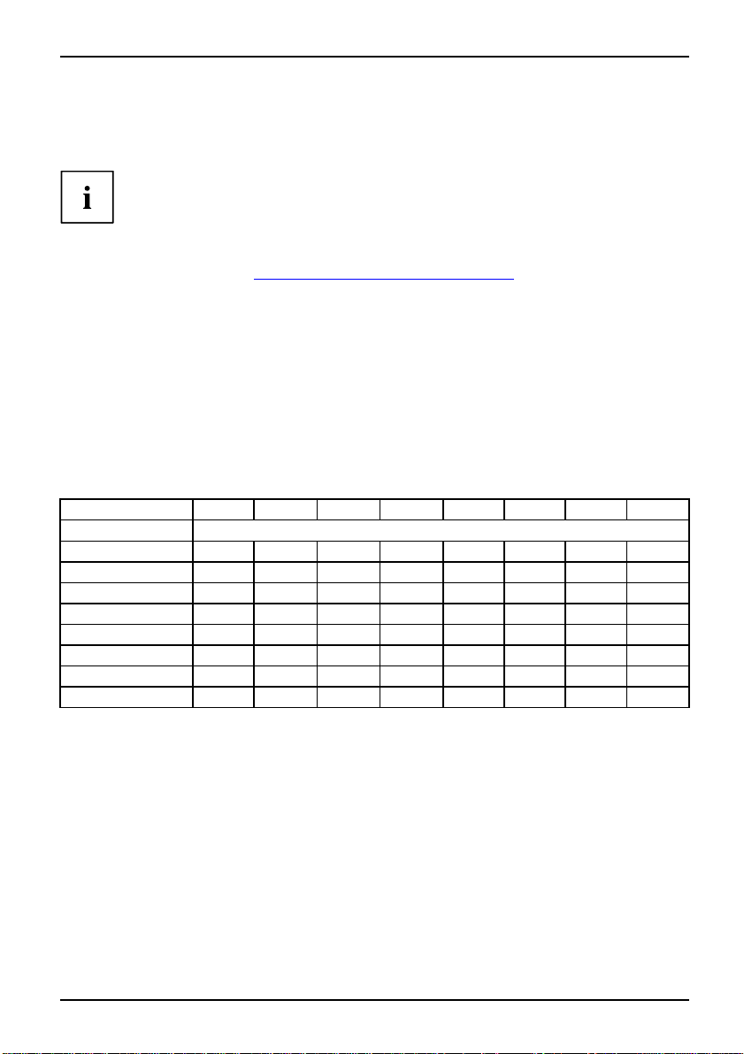
Die Zuordnung der PCI-Interrupts zu den IRQ Lines finden Sie in d er folgenden Tabelle:
On board controller
PCI INT LINE
USB 1.1
USB 2.0
SMBus
HD Audio
LAN
1(A) 2(B) 3(C) 4(D) 5(E) 6(F) 7(G) 8(H)
st
-------
1
nd
------
2
rd
-----
3
th
----
4
-------
---
--
-
BIOS-Update", Seite 7).
x
x
------
x
x
x
x
x
-----
----
---
--
-
x
A26361-D2151-Z112-1-8N19, Ausgabe 1 Deutsch - 5
Page 12

Kurzbeschreibung des Mainboard
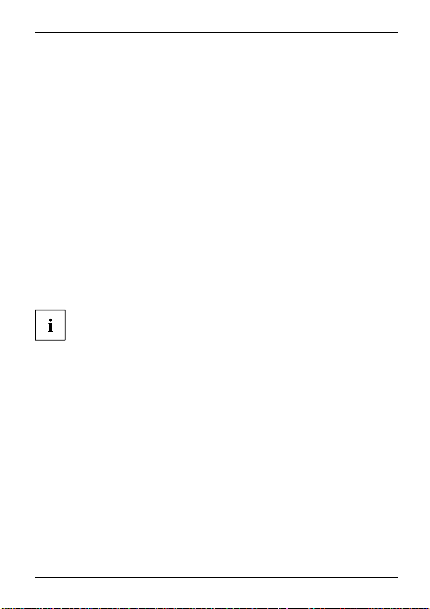
Mechanical Slot
PCI INT LINE
PCIe x16 AB
PCIe x1 CDAB
PCI 1
PCI 2
PCI 3
PCI 4
1(A) 2(B) 3(C) 4(D) 5(E) 6(F) 7(G) 8(H)
------
----
--
--
DC
CD
-
-
BA
AB
--------
--------
Verwenden Sie zuerst PCI-/PCI-Express-Steckplätze, die über eine einzige PCI IRQ Line
verfügen (kein IRQ Sharing). Wenn Sie einen anderen PCI-/PCI-Express-Steckplatz mit IRQ
Sharing benutzen müssen, überprüfen Sie, ob die Erweiterungskarte IRQ Sharing mit den
anderen Geräten auf dieser PCI IRQ Line einwandfrei unterstützt. Auch die Treiber aller Karten
und Komponenten an dieser PCI IRQ Line müssen IRQ Sharing unterstützen.
-
-
6 - Deutsch A26361-D2151-Z112-1-8N19, Ausgabe 1
Page 13
Kurzbeschreibung des Mainboard
BIOS-Update
Wann sollte ein BIOS-Update durchgeführt werden?
Fujitsu Siemens Computers stellt neue BIOS-Versionen zur Verfügung, um die Kompatibilität
zu neuen Betriebssystemen, zu neuer Software o der zu neuer Hardware zu gewährleisten.
Außerdem können neue BIOS-Funktionen integriert werden.
Ein BIOS-Update sollte auch immer dann durchgefüh rt werden, wenn ein Prob lem besteht,
das sich durch neue Treiber oder neue Software nicht beheben lässt.
Wo gibt es BIOS-Upd ates?
Im Internet unter "
www.fujitsu-siemens.com/mainboards" finden Sie die BIOS-Updates.
BIOS-Update unter DOS mit startfähiger
BIOS-Update-Diskette - Kurzbeschreibung
► Laden Sie die Update-Date i von unserer Internet-Seite auf Ihren PC.
► Legen Sie eine leere Diskette (1,44 MByte) ein.
► Führen Sie die Update-Datei aus (z. B. 2461103.EXE).
Es wird eine startfähige Update-Diskette erstellt. Lassen Sie diese Diskette im Lauf werk.
► Starten Sie den PC neu.
► Folgen Sie den Bildschirmanweisun gen.
Detaillierte Informationen zum BIOS-Update unter DOS finden Sie im Handbuch
zum "BIOS-Setup" (CD "Drivers & Utilities").
BIOS-Update unter Windows m
it dem
Utility DeskFlash
Ein BIOS-Update kann mit d
DeskFlash befindet sich au
A26361-D2151-Z112-1-8N19, Ausgabe 1 Deutsch - 7
em Utility DeskFlash auch direkt unter Windows durchgeführt werden.
f der CD "Drivers & Utilities" (unter DeskUpdate).
Page 14
Kurzbeschreibung des Mainboard
Grafik-Anschluss
Technische Da ten
Funktion:
Merkmale:
Unterstützte Bildschirmauflösungen
Abhängig vom verwendeten B
Bildschirmauflösungen für
Wenn Sie einen a nderen Bild
Bildschirmauflösungen i
Bildschirmauflösung Bildschirmfrequenz[Hz ]
640 x 480 120 32 bit
800 x 600 120 32 bit
1024 x 768 100 32 bit
1280 x 1024 100 32 bit
1600 x 1200 100 16 bit
1920 x 1440
2048 x 1536
1366 x 768 60 32 bit
1024 x 512 60 32 bit
852 x 480 60 32 bit
Intel GMA 950, 2D-/3D-Grafik-Controller, Dynamic Video memory
Technology (max. 224 MB), 400 Mhz integrierter24-Bit-RAMDAC
Display Data Chanal (DDC), 2 SDVO-Kanäle (bis zu 165 Megapixel pro
Kanal), Dual-View-Unterstützung für ADD2+- Ka rten
etriebssystem gelten die nachfolgend angegebenen
den Bildschirm-Controller auf dem Mainboard.
schirm-Controller verwe nden, finden Sie die unterstützten
n der Dokumentation zum Bildschirm-Controller.
75
75
Farben
16 bit
16 bit
8 - Deutsch A26361-D2151-Z112-1-8N19, Ausgabe 1
Page 15

Brief description of the mainboard
Brief description of the mainb
Information about boards
Be sure to observe the following for boards with ESD:
• You must always discharge static build up (e.g. by touching a grounded object)
before working.
• The equipment and tools you use must be f ree of static charges.
• Remove the power plug from the mains supply before inserting or removing
boards containing ESDs.
• Always hold boards by their edges.
• Never touch pins or conductors on the board.
An overview of the features is provided in the data sheet.
Special features
Your mainboard is available in different configuration levels. Depending on the configuration,
your mainboard is equipped with or supports special features.
This manual describes the most important properties of this mainboard.
Additional information on mainboards is contained in the "Basic information on mainboard" manual
on the "User Documentation" or "OEM Mainboard" CDs, or on the Internet.
oard
Ports and connectors
The location of the ports a
The components and connect
nd connectors of your mainboard is specified at the beginning of the manual.
ors marked are not necessarily present on the mainboard.
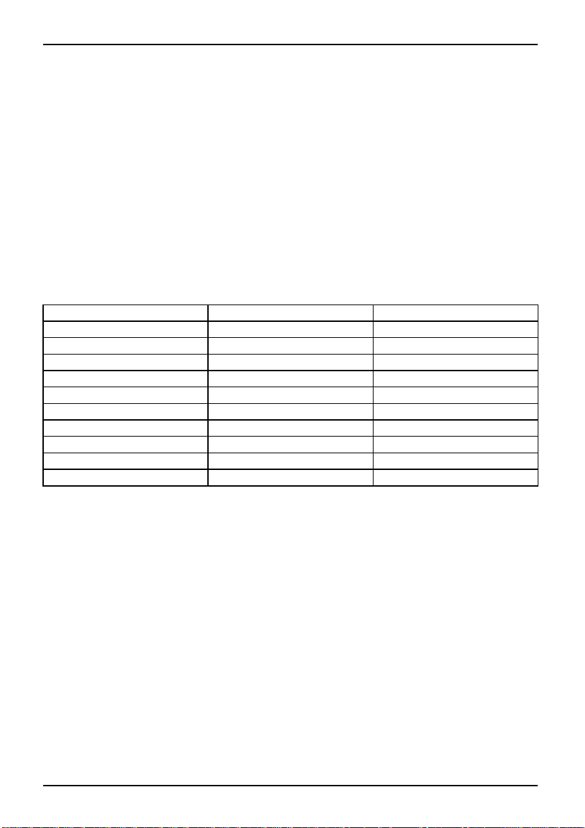
External ports
The location of the external ports of your mainboard is specified at the beginning of the manual.
PS/2 keyboard port, purple Serial port, turquoise
Parallel port/Printer, burgundy PS/2 mouse port, green
LAN port (RJ-45)
Audio input (Line in), light blue USB - Universal Serial Bus,
Audio output (Line out), light green
A26361-D2151-Z112-1-8N19, edition 1 English - 1
Microphone port, pink
black
Page 16

Brief description of the mainboard
Installing/removing processor (with heat sink)
Disconnect the system from the mains voltage before performing any of the tasks
described below. Details are contained in your system’s operating m anual.
Technical data
• Intel Core Duo with 800 or 1066 MHz front side bus in the LGA775 design (FMB06-65W)
• Intel Pentium 4 with 533/800/1 066 MHz front side bus in the LGA775
design (Mainstream FMB 05A)
• Intel Celeron D with 533 MHz Front Side Bus in the LG A775 design
• A current list of the processors supported by this mainboard is available on the
Internet at: "
www.fujitsu-siemens.com/mainboards".
Never touch the underside of the processor. Even m inor soiling such as sweat
from the skin can impair the processor’s operation or destroy the processor.
Place the processor in the socket with extreme care, as the spring contacts
of the socket are very delicate and must not be bent.
If one or more spring contacts are bent do not insert the processor in any case as
it may be damaged by doing so. Please contact the responsible vendor.
2 - English A26361-D2151-Z112-1-8N19, edition 1
Page 17

Procedure
The processor socket ist covered with a prot ective cap to protect the spring
contacts In the event of a warranty claim, the mainboard can only be taken back
by Fujitsu Siemens Computers with the protective cap attached!
b
Please note that, depending on the heat sink used, different heat sink
mounts are required on the mainboard.
Brief description of the mainboard
► Remo ve the heat sink.
► Press down the lever and unhook it.
► Lift up the frame.
► Hold the processor between your thumb
and index finger and insert it into the socket
(b) so that the marking of the processor is
alignedwiththemarkingonthesocket(a).
b
a
► Press the lever downward until it
engages again.
► Remo ve the protective cap and keep it.
► Depending on the configuration variant, you must pull a protective foil off the heat sink
or coat the heat sink with heat co nducting paste before fitting it.
► Secure the heat sink - depending on the model - with four screws or push it into the mounts.
A26361-D2151-Z112-1-8N19, edition 1 English - 3
Page 18

Brief description of the mainboard
Installing/removing main memory
Disconnect the system from the mains voltage before performing any of the tasks
described below. Details are contained in the operating manual of your syst em.
Technical data
Technology
Tota l siz e
Module size
DDR2 400 / 533 / 667 unbuffered DIMM m odules
256 Mbytes to 4Gbyte DDR2
256, 512 or 1024 Mbyte for one m
odule
A current list of the memory modules recommended for this m ainboard is available on
the Internet at: "
www.fujitsu-siemens.com/mainboards".
At least one memory module must be installed. Memory modules with different
memory capacities can be combined.
You may use only unbuffered 1.8 V memory modules without ECC.
DDR2 memory mo dules must meet the PC2-4200U, PC2-5300U
or PC2-6400U specification.
If you use more than one memory module, then make sure to distribute the
memory modules over both memory channels. By doing this you use the
performance advantages of the dual-channel mode.
Maximum system performance is given when the same memory size
is used in Channel A and Channel B.
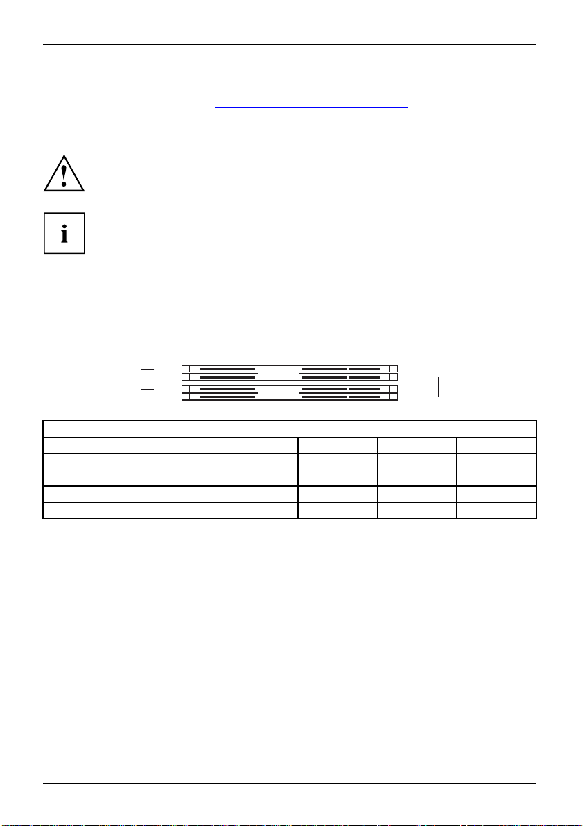
To simplify equipping, the slots are colour coded.
With a memory configuration of 4 Gbytes the visible and usable main memory can
be reduced down to 3 Gbytes (depending on the system configuration).
240-Pin;1.8V;64Bit,noECC
slot 4
slot 3
Channel B
Channel A
slot 2
slot 1
Number of inserted memory modules
Slot to be used 1 2 3 4
Channel A, slot 1
Channel A, slot 3
Channel B, slot 2
Channel B, slot 4
xxxx
xx
xxx
x
The installation/removal is described in the "Basic information on mainboard" manual.
4 - English A26361-D2151-Z112-1-8N19, edition 1
Page 19

Brief description of the mainboard
PCI bus interrupts - Selecting correct PCI slot
Extensive information on this section is contained in the "Basic information on mainboard" manual.
To achieve optimum stability, performance and compatibility, avoid the multiple use
of ISA IRQs or PCI IRQ lines (IRQ sharing). Should IRQ sharing be unavoidable,
then all devices used and their drivers must support IRQ sharing.
Which ISA IRQs are assigned to th e PCI IRQ Lines is normally automatically specified
by the BIOS (see BIOS Setup description"
Monofunctional expansio ns cards
PCI/PCI Express expansion cards require a maximum of one interrupt, which is called the PCI
interrupt INT A. Expansion cards that do not require an interrupt can be installed in any desired slot.
Multifunctional expansion cards or expansion card s with integrated PCI-PCI bridge
These expansion cards require up to four PCI interrupts: INT A, INT B, INT C, INT D. How many and
which of these interrupts are used is specified in the documentation provided with the card.
The assignment of the PCI interrupts to the IRQ Lines is shown in the following table:
On board controller
PCIINTLINE 1(A) 2(B) 3(C) 4(D) 5(E) 6(F) 7(G) 8(H)
USB 1.1
st
-------
1
nd
------
2
rd
-----
3
th
----
4
USB 2.0
SMBus
HD Audio
LAN
-------
---
--
-
BIOS update", Page 6).
x
x
------
x
x
x
x
---
--
-
x
x
----
-----
Mechanical Slot
PCIINTLINE 1(A) 2(B) 3(C) 4(D) 5(E) 6(F) 7(G) 8(H)
PCIe x16
PCIe x1 C
PCI 1
PCI 2
PCI 3
PCI 4
First use PCI/PCI Express
must use ano ther PCI/PC
properly supports IRQ s
haring with the other devices on this PCI IRQ Line. The drivers of all
cards and components on
AB
DAB
--
--
--------
--------
slots that have a single PCI IRQ Line (no IRQ sharing). If you
I Express slot with IRQ sharing, check whether the expansion card
this PCI IRQ Line must also support IRQ sharing.
------
---DC
C
D
-
-
BA
AB
-
-
A26361-D2151-Z112-1-8N19, edition 1 English - 5
Page 20
Brief description of the mainboard
BIOS update
When should a BIOS u pdate be carried out?
Fujitsu Siemens Computers makes new BIOS versions available to ensure compatibility with new operating systems, new software or new hardware. In addition, new BIOS functions can also be integrated.
A BIOS update should always also be carried out when a problem exists that cannot
be solved with new drivers or new software.
Where can I obtain BIOS updates?
The BIOS updates are available on the Internet at "
www.fujitsu-siemens.com/mainboards".
BIOS update under DOS with bootable BIOS
update floppy disk - brief description
► D ownload the update file from our website to your PC.
► In sert an empty floppy disk (1.44 Mbyte).
► R un the update file (e.g. 2461103.EXE).
A bootable update floppy disk is created. Leave this flo ppy disk in the drive.
► R e start the P C.
► Follow the instructions on screen.
Detailed information on the BIOS update under DOS is provided in the
"BIOS Setup" manual ("Drivers & Utilities" CD).
BIOS update under Windows wi
A BIOS update c an also be carried out directly under Windows with the DeskFlash utility.
DeskFlash is contained on the "Drivers & Utilities" CD (under DeskUpdate).
6 - English A26361-D2151-Z112-1-8N19, edition 1
th DeskFlash utility
Page 21
Brief description of the mainboard
Graphics port
Technical data
Function:
Features:
Possible screen resolutions
Depending on the operating
table refer to the mainboar
If you are using an external
resolutions in the docum
Screen resolution Refresh frequency [Hz] Colours
640 x 480 120 32 b it
800 x 600 120 32 b it
1024 x 768 100 32 bit
1280 x 1024 100 32 bit
1600 x 1200 100 16 bit
1920 x 1440
2048 x 1536
1366 x 768 60 32 bit
1024 x 512 60 32 bit
852 x 480 60 32 b it
Intel GMA 950, 2D/3D graphics controller, Dynamic Video memory
Technology (ma x. 224 MB), 400 Mhz integrated 24-bit RAMDAC
Display Data Channel (DDC), 2 SDVO channels (up to 165 megapixels per
channel), dual-view support for ADD2+ boards
system used, the screen resolutions in the following
d screen controller.
screen controller, you will find details of supported screen
entation supplied with the controller.
75
75
16 bit
16 bit
A26361-D2151-Z112-1-8N19, edition 1 English - 7
Page 22

Brief description of the mainboard
8 - English A26361-D2151-Z112-1-8N19, edition 1
Page 23

Brève description de la carte mère
Brève description de la carte m
Remarques relatives aux cartes
Respectez impérativement les consignes suivantes avec les cartes équipées de
composants sensibles à l’électricité statique :
• Vous devez vous décharger de l’électricité statique (en touchant un objet relié à
la terre, par exemple) avant de manipuler les cartes.
• Les appareils et outils uti
• Débranchez les câbles avant de connecter ou de déconnecter les cartes.
• Saisissez les cartes par leu
• Evitez de toucher les broche s ou les circuits d’une carte.
Vous trouverez un aperçu des caractéristiques de performances dans la fiche technique.
Caractéristiques
Votre carte mère est disponible en plusieurs niveaux d’équipement. S u ivant sa configuration,
votre carte mère possède ou supporte certaines caractéristiques.
Vous trouverez dans ce manuel une description des principales caractéristiques de cette carte mère.
Vous trouverez d’autres informations sur les cartes m ères dans le manuel "Basic information on
mainboard" sur le CD "User Documentation" ou "OEM Ma inboard" ainsi que sur Internet.
lisés doivent être dépourvus de tou te charge statique.
rs bords seulement.
ère
Ports et connecteurs
Vous trouverez au début du manuel la position des ports et de s connecteurs sur votre carte mère.
Les composants et connecteurs marqués ne sont pas obligatoirement disponibles sur la carte mère.
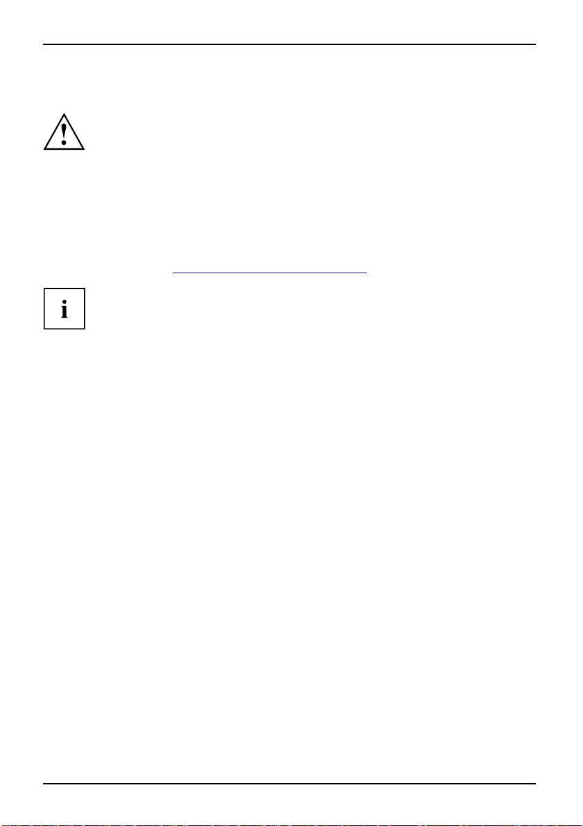
Ports externes
Vous trouverez au début du manuel la position des ports externes de votre carte mère.
Port clavier PS/2, violet Interface série, turquoise
Port parallèle/imprimante, bordeaux Port souris PS/2, vert
Port LAN (RJ-45)
Entrée audio (Line in), bleu ciel USB - Universal Serial Bus, noir
Sortie audio (Line out), vert clair
A26361-D2151-Z112-1-8N19, édition 1 Français - 1
Port microphone, rose
Page 24

Brève description de la carte mère
Monter/démonter le processeur (avec refroidisseur)
Avant de procéder à toutes les étapes décrites ici, il est indispensable de s éparer
intégralement votre système de la tension de secteur ! Vous trouverez à ce propos
d’autres indications détaillées dan s le manuel d’utilisation de votre système.
Caractéristiques techniques
• Intel Core Duo avec bus front
• Intel Pentium 4 avec bus frontal 533/800/1066 MHz en configuration
LGA775 (Mainstream FMB 05A)
• Intel Celeron D avec bus front
• Vous trouverez une liste actualisée des processeurs supportés par cette carte mère sur
Internet à l’adresse suivante : "
Ne touchez jamais la face inférieure du processeur. De légères salissures comme le
gras de la peau peuvent perturber le fonctionnement du processeur ou le détruire.
Posez le processeur dans son logement avec la plus grande précaution car les
broches du logement sont très sensibles et ne doivent pas être pliées.
Si une ou plusieurs broches sont pliées, ne posez en aucun cas le processeur dans le
logement sous peine de l’endommager. Adressez-vous directement à votre revendeur
al 800 ou 1066 MHz en configuration LGA775 (FMB06-65W).
al 533 MHz en configuration LGA775
www.fujitsu-siemens.com/mainboards".
2 - Français A26361-D2151-Z112-1-8N19, édition 1
Page 25

Méthode
Le logement réservé au processeur est r ecouvert d’un capuchon protecteur qui
protège les broches. En cas de garantie, la carte mère sera uniquement acceptée
par Fujitsu Siemens Computers si le capuchon protecteur est en place !
Veuillez tenir compte du fait que les clips de fixation du refroidisseur nécessaires
sur la carte mère varient en fonction du type de refroidisseur utilisé.
Brève description de la carte mère
► Retire z le refroidisseur.
► Appuyez sur le levier et écartez-le.
► Relevez le support vers le ha
► Saisissez le processeur entre le pouce
et l’index et posez-le dans son logement
(b) de telle sorte que la position le
marquage sur le processeur coïncide avec
b
b
a
le marquage sur le logement (a).
► Rab aissez le levier jusqu
se remette en place.
► Retire z le capuchon protecteur et
conservez-le.
ut.
’à ce qu’il
► Suivant le modèle, vous devez soit retirer un film de protection du refroidisseur soit enduire
le refroidisseur d’une pâte à conductivité thermique avant de le remonter.
► Fixez le refroidisseur – suivant le modèle – à l’aide de quatre vis ou enfichez-le dans les fixations.
Monter/démonter la mémoire principale
Avant de procéder à toutes les étapes décrites ici, il est indispensable de séparer
intégralement votre système de la tension de secteur ! Vous trouverez à ce propos
d’autres indications détaillées dans le manuel de votre système.
Caractéristiques techniques
Technologie
Taille totale
Taille du
module
A26361-D2151-Z112-1-8N19, édition 1 Français - 3
Modules DIMM DDR2 400 / 533 / 667 sans tampon
sans CCE
DDR2 256 M oc tets à 4 Goctets
256, 512 ou 1024 Moctets par module
240 broches; 1,8 V; 64 bits,
Page 26
Brève description de la carte mère
Vous trouverez une liste actualisée des mo dules mémoire recommandés pour cette carte mère
sur Internet à l’adresse suivante : "
www.fujitsu-siemens.com/mainboards".
Au moins un module mémoire doit être monté. Il est possible de combiner des
modules mémoire de capacités différentes.
Vous ne pouvez utiliser que des modules mémoire 1,8 V sans tampon sans CCE.
Les modules mémoire DDR2 doivent être conformes à la spécification
PC2-4200U, PC2-5300U ou PC2-6400U.
Si vous utilisez plus d’un mo
sur les deux canaux mémoire.
gains de performances offer
Les performances système ma
vive est la même dans le canal
Pour faciliter le montage d
dule mémoire, veillez à répartir les modules mémoire
Cette précaution vous permet de bénéficier des
ts par le mode bi-canal (dual channel).
ximales s’obtiennent lorsque la quantité de mémoire
A et dans le canal B.
es modules, les emplacements (slots) sont
marqués de codes couleur.
Dans le cas d’une configurat
peutêtreréduiteà3Gocte
slot 4
slot 3
ion mémoire de 4 Goctets, la mémoire visible et utilisable
ts maximum (selon la configuration du système).
Channel B
Channel A
Nombre de modules mémoir
slot 2
slot 1
e installés
Emplacement à utiliser 1 2 3 4
canal A, slot 1
canal A, slot 3
canal B, slot 2
xxxx
xx
xxx
canal B, slot 4
Le montage/démontage est décrit dans le manuel "Basic information on mainboard".
x
4 - Français A26361-D2151-Z112-1-8N19, édition 1
Page 27

Brève description de la carte mère
Interruptions de BUS PCI - Sélection du logement PCI adéquat
Vous trouverez de plus amples informations sur ce chapitre dans le manuel
"Basic information on Mainboard".
Afin d’obtenir une stabilité, des performances et une compatibilité optimales,
évitez l’utilisation multiple de lignes IRQ ISA ou IRQ PCI (IRQ Sharing).
Si l’IRQ Sharing est inévitable, tous les périphériques impliqués et leurs
pilotes doivent supporter l’IRQ Sharing.
L’affectation des IRQ ISA aux lignes IRQ PCI est normalement fixée automatiquement par
le BIOS (voir description "
Cartes d’extension monofonctionnelles
Les cartes d’extension PCI/PCI Express ont besoin tout au plus d’une interruption,
désignée comme interruption PCI INT A. Les cartes d’extension ne nécessitant aucune
interruption peuvent être montées dans n’importe quel logement.
Cartes d’extension multifonctionnelles ou cartes d’extension avec pont PCI-PCI intégré
Ces cartes d’extension nécessitent jusqu’à quatre interruptions PCI : INT A, INT B,
INT C, INT D. Pour savoir combien et lesquelles de ces interruptions sont utilisées,
reportez-vous à la d ocumentation fournie avec la c arte.
L’affectation des interruptions PCI aux lignes I RQ est reprise dans le tableau suivant :
On board controller
PCIINTLINE 1(A) 2(B) 3(C) 4(D) 5(E) 6(F) 7(G) 8(H)
USB 1.1
2
USB 2.0
SMBus
HD Audio
LAN
Setup du BIOS: mise à jour" , Page 7).
st
-------
1
nd
------
rd
-----
3
th
----
4
-------
---
--
-
x
x
------
x
-----
x
----
x
---
x
x
--
-
x
A26361-D2151-Z112-1-8N19, édition 1 Français - 5
Page 28

Brève description de la carte mère
Mechanical Slot
PCIINTLINE 1(A) 2(B) 3(C) 4(D) 5(E) 6(F) 7(G) 8(H)
PCIe x16 AB
PCIe x1 C
PCI 1
PCI 2
PCI 3
PCI 4
--
--
--------
--------
DAB
------
----
D
C
CD
-
-
BA
AB
Utilisez d’abord les logements PCI/PCI Expre ss qui disposent d’une seule ligne IRQ PCI
(pas d’IRQ Sharing). Si vous devez utiliser un autre logement PCI/PCI Express avec IRQ
Sharing, vérifiez si la carte d’extension supporte intégralement l’IRQ Sharing avec les autres
périphériques sur cette ligne IRQ PCI. Les pilotes de toutes les cartes et composants de
cette ligne IRQ PCI doivent égalemen t supporter l’IRQ Sharing.
-
-
6 - Français A26361-D2151-Z112-1-8N19, édition 1
Page 29

Brève description de la carte mère
SetupduBIOS:miseàjour
Quand une mise à jour du BIOS est-elle nécessaire ?
Fujitsu Siemens Computers propose de nouvelles versions du BIOS afin de garantir la compatibilité
avec les nouveaux systèmes d’exploitation, les nouveaux logiciels ou le nouveau matériel.
De nouvelles fonctionnalités du BIOS peuvent en outre être intégrées.
Une mise à jour du BIOS est toujours nécessaire en cas de problème ne pouvant être
résolu par l’utilisation de nouveaux pilotes ou logiciels.
Où se procurer des mises à jour du BIOS ?
Les mises à jour du BIOS sont disponibles sur Internet à l’adresse suivante :
"
www.fujitsu-siemens.com/mainboards".
MiseàjourduBIOSsousDOSavecdisquettedemise
à jour du BIOS opérationnelle - Brève description
► Téléchargez sur votre PC le fichier de mise à jour sur notre page Internet.
► Introduisez une disquette vierge (1,44 Moctets).
► Lancez l’exécution du fi chier de mise à jour (p. ex. 2461103.EXE).
Une disquette amorçable de mise à jour est créée. Laissez cette disquette
dans le lecteur de disquettes.
► Redémarrez le PC.
► Suivez les inst ructions à l’écran.
Vous trouverez des informations détaillées sur la mise à jour du BIOS sous DOS
dans le manuel "BIOS-Setup" (CD "D rivers & Utilities").
MiseàjourduBIOSsousWin
dows avec
l’utilitaire DeskFlash
Le BIOS peut également êt
DeskFlash se trouve sur l
A26361-D2151-Z112-1-8N19, édition 1 Français - 7
re mis à jour directement sous Windows avec l’utilitaire DeskFlash.
e CD "Drivers & Utilities" (sous DeskUpdate).
Page 30
Brève description de la carte mère
Port graphique
Caractéristiques techniques
Fonction :
Caractéristiques : Display Data Channel (DDC), 2 canaux SDVO (max. 165 mégapixels par
Résolutions d’écran supportées
Le contrôleur d’écran de la carte mère présente les résolutions d’écran indiquées
ci-après, en fonction du système d’exploitation utilisé.
Si vous utilisez un autre contrôleur d’écran, les résolutions d’écran supportées sont
reprises d ans la documentation relative au contrôleur d’écran.
Résolution d ’écran Fréquence de l’écran [Hz] Couleur
640 x 480 120 32 bits
800 x 600 120 32 bits
1024 x 768 100 32 bits
1280 x 1024 100 32 bits
1600 x 1200 100 16 bits
1920 x 1440
2048 x 1536
1366 x 768 60 32 bits
1024 x 512 60 32 bits
852 x 480 60 32 bits
Intel GMA 950, Contrôleur graphique 2D/3D, technologie Dynamic Video
Memory (224 Mo max.), RAMDAC 24 bits 400 Mhz intégré
canal), support Dual View pour cartes ADD2+
75
75
16 bits
16 bits
8 - Français A26361-D2151-Z112-1-8N19, édition 1
Page 31

Краткое описание материнской платы
Краткое описание материнской
Указания по модулям
Для модулей с EGB обязательно учитывайте следующее:
• Перед работой с модулями требуется статически разрядить свое тело
(например посредством касания какого-либо заземленного предмета).
• Исключите возможность статического заряда используемых устройств
и инструментов.
• Перед установкой или снятием модулей выньте вилку сетевого кабеля из
розетки.
• Касайтесь только кромок модулей.
• Не прикасайтесь к штырьковым выводам или печатным проводникам
модуля.
Обзор производственных показателей Вы найдете в техническом паспорте.
Отличительные особенности
Вы можете приобрести Вашу материнскую плату в различных конфигурационных
исполнениях. Ваша материнская плата в зависимости от своей конфигурации
обладает определенными показателями или поддерживает их.
В этом Руководстве по эксплуатации Вы найдете описание важнейших
свойств этой материнской платы.
Дальнейшую информацию о материнских платах Вы найдете в руководстве "Basic
information on mainboard" ("Базисная информация о материнской плате") на компакт-диске
"User Documentation" или "OEM Mainboard" или же в Internet.
платы
Порты и разъемы
Информацию о расположении портов и разъемов на Вашей материнской плате
Вы найдете в начале Руководства по эксплуатации.
Помеченные компоненты и штекерные разъемы могут отсутствовать на материнской плате.
A26361-D2151-Z112-1-8N19, издание 1 Pycckuй -1
Page 32
Краткое описание материнской платы
Внешние порты
Информацию о расположении внешних портов на Вашей материнской плате Вы
найдете в начале Руководства по эксплуатации.
Порт клавиатуры PS/2,
фиолетовый
Параллельный
интерфейс/принтер,
темно-красный
Порт LAN (RJ-45)
Последовательный интерфейс,
бирюзовый
Порт мыши PS/2, зеленый
Порт микрофона, розовый
Aудиовход (Line in),
светло-синий
Аудиовыход (Line out),
светло- зеленый
USB - Universal Serial Bus
(универсальная последовательная
шина), черный
Монтаж/демонтаж процессора (срадиатором)
Для осуществления всех
полностью отключена от
об этом Вы найдете в ру
описанных здесь работ Ваша система должна быть
сетевого напряжения! Более подробную информацию
ководстве по эксплуатации Вашей системы.
Технические данные
• Intel Core Duo с 800 или
исполнении LGA775 (FM
• Intel Pentium 4 с 533/800/1066 M Гц Front Side Bus вконструктивном
исполнении LGA775 (Mainstream FMB 05A)
•IntelCeleronDс 533 M
• Актуальный список процессоров, поддерживаемых этой материнской платой, Вы
найдете в Internet на сайте: "
Ни в коем случае не прикасайтесь к нижней стороне процессора. Уже
малейшие загрязнения, как например, жир на коже, могут негативно
сказаться на работе процессора или же разрушить его. Уст анавливайте
процессор в разъем очень осторожно, поскольку пружинные контакты на
разъеме очень чувствительны и их нельзя изгибать.
В том случае, если один или несколько пружинных контактов изогнуты, ни в
коем случае не устанавливайте процессор, поскольку из-за этого он может быть
поврежден. Пожалуйста, обратитесь непосредственно к компетентному продавцу
1066 MГц Front Side Bus в конструктивном
B06-65W)
Гц Front Side Bus в конструктивном исполнении LGA775
www.fujitsu-siemens.com/mainboards".
2 - Pycckuй A26361-D2151-Z112-1-8N19, издание 1
Page 33

Способ действия
Разъем для процессора закрыт защитной пластинкой для защиты пружинных
контактов. В случае предъявления гарантийных претензий возвращаемая
материнская плата может быть принята только при наличии прикрепленной
защитной пластинки фирмы Fujitsu Siemens Computers!
b
b
Краткое описание материнской платы
► Удалите радиатор.
► Нажмите на рычаг и поднимите его.
► Поднимите устройство крепл
► Держите процессор большим и
указательным пальцами и вставьте его
вразъем(b) так, чтобы маркировка на
процессоре по своему расположению
полностью совпала с маркировкой
a
на разъеме (а).
► Нажмите на рычаг вниз до щ
означающего, что процес
► Удалите защитную пластинку и
сохраняйте ее.
ения вверх.
елчка,
сор закреплен.
Пожалуйста, уч
материнской пл
► В зависимости от варианта конфигурации перед установкой радиатора Вы должны снять
защитную пленку с радиатора, или же покрыть радиатор теплопроводящей пастой.
► Укрепите радиатор (в зависимости от конфигурации) при помощи четырех
шурупов или же вставьте его в крепеж.
итывайте то, что в зависимости от используемого радиатора на
ате требуются различные устройства крепления радиатора.
Монтаж/демонтаж ОЗУ
Для осуществления всех описанных здесь работ Ваша система должна быть
полностью отключена от сетевого напряжения! Более подробную информацию
об этом Вы найдете в руководстве по эксплуатации Вашей системы.
A26361-D2151-Z112-1-8N19, издание 1 Pycckuй -3
Page 34

Краткое описание материнской платы
Технические данные
Техноло гия
DDR2 400 / 533 / 667 модули DIMM без буферизации
240-Pin;
1,8 В;64бит,
без ECC
Общий
от 256 Мбайт до 4 Гбайт DDR2
объем
памяти
Объем
256, 512 или 1024 Mбайт на кажд
ом модуле
памяти
модулей
Актуальный список модулей памяти, рекомендованных для этой материнской платы, Вы
найдете в Internet на сайте: "
www.fujitsu-siemens.com/mainboards".
Необходимо встроить хотя бы один модуль памяти. Можно комбинировать
модули памяти с различной ёмкостью ЗУ.
Допускается применение только модулей памяти без буферизации 1,8 ВбезECC.
Модули памяти DDR2 должны соответствовать спецификации PC2-4200U-
или PC2-5300U- или PC2-6400U.
Если вы используете больше одного модуля памяти, следите за тем, чтобы
модули памяти были распределены на обоих каналах с памятью. За
счет этого Вы будете использовать преимущества рабочих характеристик
двухканального режима Dual-Channel-Mode.
Максимальные рабочие характеристики достигаются в том случае, если на каналах
Channel A и Channel B используются модули памяти с одинаковыми размерами.
Для облегчения комплектации элементами разъемы (Слоты)
обозначены цветной маркировкой.
При конфигурации памяти размером в 4 Гбайта видимое и используемое ОЗУ
может быть сокращено до 3 Гбайтов (в зависимости от конфигурации системы).
slot 4
slot 3
Channel B
Channel A
slot 2
slot 1
Количество вставленных модулей памяти
Используемый разъем 1234
канал Channel A, Слот 1
канал Channel A, Слот 3
канал Channel B, Слот
канал Channel B, Слот 4
2
xxxx
xx
xxx
x
Монтаж и демонтаж описаны в руководстве по эксплуатации "Basic information on mainboard".
4 - Pycckuй A26361-D2151-Z112-1-8N19, издание 1
Page 35

Краткое описание материнской платы
Шины прерывания PCI – выбор правильного PCI-разъема
Подробную информацию к этому разделу Вы найдете в руководстве "Basic information
on mainboard" ("Базисная информация о материнской плате").
Для того, чтобы достичь оптимальной стабильности, рабочих характеристик
и совместимости, избегайте многократного использования ISA IRQ или PCI
IRQ Lines (IRQ Sharing). Если нельзя отказаться от механизма совместного
использования прерываний (IRQ Sharing), то все задействованные устройства
и их драйверы должны поддерживать IRQ Sharing.
Обычно BIOS автоматически назначает соответствующие ISA IRQ на PCI IRQ
Lines (см. описание "
Монофункциональные расширительные платы
Для расширительных плат PCI-/PCI-Exp res s требуется максимально одна линия прерывания,
которую называют PCI-прерыванием INT A. Расширительные платы, не нуждающиеся
в линиях прерывания, можно встраивать в любой разъем.
Многофункциональные расширительные платы или расширительные
платы со встроенным мостом PCI-PCI
Эти расширительные платы требуют до четырех PCI-прерываний:INTA,INTB,
INT C, INT D. Информацию о том, сколько прерываний и какие из них используются,
Вы найдете в документации, поставляемой вместе с платой.
Назначение прерываний PCI на IRQ Lines Вы найдете в следующей таблице:
Обновление BIOS", Сторона 7).
On board controller
PCIINTLINE 1(A) 2(B) 3(C) 4(D) 5(E) 6(F) 7(G) 8(H)
USB 1.1
USB 2.0
SMBus
HD Audio
LAN
A26361-D2151-Z112-1-8N19, издание 1 Pycckuй -5
st
-------
1
nd
------
2
rd
-----
3
th
----
4
-------
---
--
-
x
x
------
x
-----
x
----
x
---
x
x
--
-
x
Page 36

Краткое описание материнской платы
Mechanical Slot
PCIINTLINE 1(A) 2(B) 3(C) 4(D) 5(E) 6(F) 7(G) 8(H)
PCIe x16 AB
PCIe x1 C
PCI 1
PCI 2
PCI 3
PCI 4
--
--
--------
--------
DAB
------
----
D
C
CD
-
-
BA
AB
Используйте сначала разъемы PCI-/PCI-Express, которые обладают лишь одной
линией PCI IRQ Line (без механизма IRQ Sharing). Если Вам нужно использовать
другой разъем PCI-/PCI-Express смеханизмомIRQ Sharing, убедитесь в том, что
расширительная карта безукоризненно поддерживает IRQ Sharing с другими устройствами
на этой линии PCI IRQ Line. Также и драйверы всех плат и компонент на этой
линии PCI IRQ Line должны поддерживать IRQ Sharing.
-
-
6 - Pycckuй A26361-D2151-Z112-1-8N19, издание 1
Page 37

Краткое описание материнской платы
Обновление BIOS
Когда необходимо обновить BIOS?
Фирма Fujitsu Siemens Computers предоставляет в распоряжение пользователя новые
версии BIOS для того, чтобы обеспечить совместимость с новыми операционными
системами, с новым программным обеспечением или с новым техническим обеспечением.
Кроме того, имеется возможность для интеграции новых функций BIOS.
BIOS всегда необходимо обновлять также и в том случае, если имеется проблема, которую не
удается удалить за счет установки нового драйвера или нового программногообеспечения.
Где можно найти новые версии BIOS?
Вы найдете новые версии BIOS в Inter net на сайте "
www.fujitsu-siemens.com/mainboards" .
Обновление BIOS в DOS припомощидискеты
начальной загрузки с обновленной версией
BIOS - краткое описание
► Скачайте файл с обновленной версией с нашего сайта в Internet на Ваш компьютер.
► Вставьте в дисковод пусту
► Запустите файл с обновленной версией (например, 2461103.EXE).
Будет создана дискета нач
Оставьте дискету в дисков
► Перезагрузите ПК.
►Выполняйтеуказания, высв
юдискету(1,44 Мб).
альной загрузки с обновленной версией.
оде.
ечивающиеся на дисплее.
Подробную информацию об о
"BIOS-Setup" (компакт-д
бновлении BIOS в DOS Вы найдете в руководстве
иск "Drivers & Utilities").
Обновление BIOS в Windows сиспользованием утилиты DeskFlash
Обновление BIOS может быть также осуществлено с помощью утилиты
DeskFlash непосредственно в Windows. DeskFlash находится на компакт-диске
"Drivers & Utilities" (в разделе DeskUpdate).
A26361-D2151-Z112-1-8N19, издание 1 Pycckuй -7
Page 38
Краткое описание материнской платы
Графический порт
Технические данные
Функция:
Отличительные
особенности:
Поддерживаемые параметры разрешения экрана
В зависимости от используе
разрешения экрана действи
В случае использования дру
параметры разрешения эк
Разрешение экрана Частота экрана [Гц] Цвета
640 x 480 120
800 x 600 120
1024 x 768 100
1280 x 1024 100
1600 x 1200 100
1920 x 1440
2048 x 1536
1366 x 768 60
1024 x 512 60
852 x 480 60
Intel GMA 950, графический контроллер 2D/3D, Dynamic Video memory
Technology (макс. 224 Мб), встроенный RAMDAC 24 бит 400 MГц
Display Data Channel (DDC), 2 канала 2SDVO(каждый канал до 165
мегапикселей), поддержка Dual View для плат ADD2+
мой операционной системы указанные ниже параметры
тельны для контроллера монитора на материнской плате.
гого контроллера монитора Вы найдете поддерживаемые
рана в документации на контроллер монитора.
32 бит
32 бит
32 бит
32 бит
16 бит
75
75
16 бит
16 бит
32 бит
32 бит
32 бит
8 - Pycckuй A26361-D2151-Z112-1-8N19, издание 1
Page 39

Ana kartınkısa tanımı
Ana kartınkısa tanımı
Yapı gruplarına ilişkin bilgiler
EGB’li yapı gruplarında mutlaka şunlara dikkat edin:
• Modüller ile çalışmadan önce kendinizdeki statik yüklenmeyi deşarj etmelisiniz
(örneğin topraklanmış bir cisime dokunarak).
•Kullanılan cihaz ve aletlerde statik yüklenme olmamalıdır.
• Modülleri yerleştirmeden veya çekmeden önce şebeke fişini prizden çekiniz.
• Modülleri yalnız kenarından tutunuz.
• Modülün üzerindeki bağlantı uçlarına veya iletkenlere dokunmayın.
Performans özellikleriyle ilgili bir genel bakışı bilgi sayfasında bulabilirsiniz.
Özel karak teristikleri
Anakartınızçeşitli donanım kademelerinde mevcuttur. Ana kartınızınkonfigürasyonuna
bağımlı olarak ana kartınız belirli özelliklere sahiptir veya destekler.
Bu anakartın önemli özellikleri bu el kitabı içinde açıklanmıştır.
Anakartlara ilişkin daha fazla bilgiyi "User Documentation" veya "OEM Mainboard" CD’si üzerindeki
"Anakart Temel Bilgileri" el kitabı içinde" yada "internette bulabilirsiniz."
Bağlantılar ve fişli konektörler
Ana kart girişlerinizin ve soket bağlantıların ızın konumunu el kitabınınbaşlangıcında bulabilirsiniz.
İşaretlenmiş olan komponen tlerin ve fişli konektörlerin anakart üzerinde mevcut olması şart değildir.
Harici bağlantılar
Ana kart harici girişlerinizin konumunu el kitabınınbaşlangıcında bulabilirsiniz.
PS/2-klavye bağlantı yeri, mor Seriyel port, turkuaz
Paralel bağlantı yeri / Yazıcı, burgunt PS/2-Fare bağlantı yeri, yeşil
LAN-bağlantısı (RJ-45) Mikrofon bağlantı yeri, pembe
Audio girişi (Line in), açıkmavi
Audio çıkışı (Line out), açıkyeşil
A26361-D2151-Z112-1-8N19, basım1 Türkçe-1
USB - Üniversel Seriyel Bus,
siyah
Page 40
Ana kartınkısa ta nımı
İşlemcinin takılması / sökülmesi (soğutuculu)
Burada açıklanan tüm çalışma
tamamen ayırılmış olması şar
sisteminizin işletme kılavu
lar için sisteminizin şebeke v oltajı ndan
ttır! Bununla ilgili daha ayrıntılı bilgileri
zu içinde bulabilirsiniz.
Teknik veriler
• Inter Core Duo 1066 veya 800 MHz Front Side Bus’lı, LGA775 model (FMB06-65W)
• 533/800/1066 MHz Front Side Bus’lı, LGA775 model Intel Pentium 4 (MainstreamFMB 05A)
• 533 MHz Front Side Bus’lı, LGA775 model Intel Celeron D
•Buanakarttarafından desteklenen işlemcilerin güncel bir listesini Internet’te şu
adreste bulabilirsiniz: "
Asla işlemcinin alt yüzüne dokunmayın. Derinizin üzerinde bulunan örneğin yağ
gibi hafif kirler dahi işlemcinin çalışmasını olumsuz etkileyebilir veya işlemciyi tahrip
edebilir. İşlemci yuvasınınyaylı kontakları çokhassasolduğundan ve bükülmeleri
yasak olduğundan işlemciyi çok itinalı bir şekilde yuvasına oturtun.
Bir veya birden fazla yayl ı kontak bükülmüşse işlemciyi kesinlikle yerleştirmeyin, aksi
takdirde işlemciye hasar verilebilir. Lütfen direkt olarak sizin için yetkili satıcıya ba şvurun
www.fujitsu-siemens.com/mainboards".
2 - Türkçe A26361-D2151-Z112-1-8N19, basım1
Page 41

İzlenecek yol
Ana kartınkısa tanımı
İşlemcinin yuvası yaylı kon
Garanti durumunda anakart
Siemens Computers tarafın
b
b
Anakart üzeri
tutucularını
► Modeline göre soğutma bloğundan bir koruyucu folyoyu çıkarmanız ge rekecektir veya bloğu
yerine oturtmadan önce soğutma bloğuna ısı iletme malzemesi sürmelisiniz.
► Soğutma bloğu
nde, kullanılan soğutma bloğuna göre farklı soğutma bloğu
n gerekli olduğunu lütfen dikkate alın.
nu - modeline göre - dört cıvata ile tespit edin veya bağlantı yerlerine yerleştirin.
takların korunması için bir koruyucu kapakla örtülmüştür.
ınyalnızca koruyucu kapak takılı vaziyette ise Fujitsu
dan geri alınması mümkündür!
► Soğutma bloğunu çıkarın.
► Manda lın üzerine bastırın ve yerinden
çıkarın.
► Tutucuyu yukarıya doğru açın.
►İşlemciyi başparmağınızveişaret
parmağınızla tutun ve işlemcinin işareti
yuvadaki işaretle örtüşecek (a) şekilde
işlemciyi yuvasının(b)içinetakın.
a
► Manda lı yerine geçinceye kadar
aşağıya bastırın.
► Koruyucu kapağı çıkarın ve bunu saklayın.
A26361-D2151-Z112-1-8N19, basım1 Türkçe-3
Page 42
Ana kartınkısa ta nımı
Ana belleğin takılması /sökülmesi
Burada açıklanan tüm çalışmalar için sisteminizin şebeke voltajından
tamamen ayırılmış olması şarttır! Bununla ilgili daha ayr ıntılı bilgileri
sisteminizin işletme kılavuzu içinde bulabilirsiniz.
Teknik veriler
Teknoloji
Toplam
büyüklük
Modül boyutu Modül başına 256, 512 veya 1024 Mbyte
DDR2 400 / 533 / 667 tampon belleksiz DIMM Modülü 240-Pin; 1,8 V; 64 Bit, ECC
olmadan
256MBytesila4GByteDDR2
Bu ana kart için tavsiye edi
adreste bulabilirsiniz
En az bir adet bellek modü
olan bellek modüllerini
Yalnızca ECC’siz tampo
DDR2 bellek modüllerini
spesifikasyonuna uygun
len hafıza modüllerinin güncel bir listesini Internet’te şu
: "
www.fujitsu-siemens.com/mainboards".
lünün takılı olması şarttır. Farklı bellek kapasitesine sahip
n kombinasyonu mümkündür.
n belleksiz 1,8 V bellek modüllerinin kullanılması serbes ttir.
n PC2-4200U-, PC2-5300U- veya PC2-6400U-
olması şarttır.
Eğer birden fazla bellek modülü kullanırsanız, bellek modüllerini her iki
bellek kanalına ayırmaya dikkat edin. Bu şekilde Dual-Channel modunun
performans avantajlarından faydalanmış olursunuz.
A kanalında ve B kanalında aynı hafıza büyüklüğü kullanıldığında maksimum sistem performansı belirtilmiştir.
Bellek donatma işleminin kolaylaştırılması için bellek yuvaları (Slots) renklidir.
4 Gbyte olan bir bellek konfigürasyonunda görülebilen ve kullanılabilen ana bellek
3 Gbyte’a kadar azaltılmış olabilir (sistemin konfigürasyonuna bağımlıdır).
slot 4
slot 3
Channel B
Channel A
slot 2
slot 1
Tak ılı olan bellek mod ülü sayısı
Kullanılacak yerler 1 2 3 4
Kanal A, Soket 1
Kanal A, Soket 3
Kanal B, Soket 2
xxxx
xx
xxx
Kanal B, Soket 4
x
Takma/sökme işlemi "
Ana kart temel bilgiler" el kitabında açıklanmıştır.
4 - Türkçe A26361-D2151-Z112-1-8N19, basım1
Page 43
Ana kartınkısa tanımı
PCI-Bus-Interrupts - Doğru PCI yuvasının seçilmesi
Bu bölümle ilgili geniş bilgileri "Ana kart temel bilgiler" el kitabında bulabilirsiniz.
Optimal stabilite, performans ve uyumlulu ğu elde etmek için ISA IRQ’larınveyaPCIIRQ
Line’ların çoklu kullanımından (IRQ Sharing) kaçının. Eğer IRQ Sharing kaçınılmaz bir
durum ise, ilgili tüm aygıtlarınvebunların sürücülerinin IRQ Sharing’i desteklemesi şarttır.
PCI IRQ Line’larına hangi ISA IRQ’ların tayin edileceği normalde BIOS tarafından otomatik
olarak belirlenir (bkz.açıklama "
Tek fonksiyon lu genişletme kartları
PCI-/PCI express genişletme kartları maksimum bir kesme isteğine (Interrupt) ihtiyaç
duyar ve bu PCI-Interrupt INT A olarak tanımlanır. Kesme isteğine ihtiyaç duymayan
genişletme kartları herhangi bir yuva içine takılabilir.
Çok fonksiyonlu genişletme kartları veya entegre PCI-PCI köprülü genişletme kartları
Bu geliştirme kartları dört PCI-Interrupt‘a kadar ihtiyacı vardır: INT A, INT B, INT C, INT D. Bu
Interrupt’ların kaç sayıda ve hangilerinin kullanılacağı gönderilen kartların belgesinden alabilirsiniz.
Hangi PCI-Interrupt’ın hangi IRQ Line’larına ait olduğuaşağıdaki tabloda gösterilmiştir:
On board kumanda
PCIINTLINE 1(A) 2(B) 3(C) 4(D) 5(E) 6(F) 7(G) 8(H)
USB 1.1
st
1
nd
2
rd
3
th
4
USB 2.0
SMBus
HD Audio
LAN
BIOS-Update (Güncelleştirme)", Sayfa 7).
-------
------
-----
----
x
x
---
x
--
-------
---
--
-
x
x
------
x
-----
----
x
-
x
A26361-D2151-Z112-1-8N19, basım1 Türkçe-5
Page 44

Ana kartınkısa ta nımı
Mechanical Slot
PCIINTLINE 1(A) 2(B) 3(C) 4(D) 5(E) 6(F) 7(G) 8(H)
PCIe x16 AB
PCIe x1 C
PCI 1
PCI 2
PCI 3
PCI 4
--
--
--------
--------
DAB
------
----
D
C
CD
-
-
BA
AB
-
-
İlkönce tek bir IRQ Line’a sahip olan PCI-/PCI express yuvalarını kullanın (IRQ Sharing
yapmayın). Eğer IRQ Sharing ile başka b ir PCI-/PCI express yuvayı kullanmak zorunda kalırsanız,
genişletme ka rtının, başka aygıtlarla IRQ Sharing’i bu PCI IRQ Line’ı üzerinde kusursuz bir
şekilde destekleyip desteklemediğini kontrol edin. Bu PCI IRQ Line’ı üzerindeki tüm k artları n
ve komponentlerin sürücüleri de IRQ Sharing’i dest eklemek zorundadır.
6 - Türkçe A26361-D2151-Z112-1-8N19, basım1
Page 45

Ana kartınkısa tanımı
BIOS-Update (Güncelleştirme)
Ne zaman bir BIOS-Update yapılmalıdır?
Yeni işletim sistemlerine, yeni yazılımlara veya yeni donanımlara uyumluluğu garantilemek
için Fujitsu Siemens Computers yeni BIOS versiyonlarını kullanıma sunmaktadır. Bunun
dışında yeni BIOS fonksiyonlarının entegre edilmesi müm kündür.
Bir sorunun yeni sürücü (driver) veya yeni yazılım sayesinde giderilemediği durumlarda
da daima BIOS-Update gerçekleştirilmelidir.
BIOS-Update’ler nereden temin ed ilebili r?
BIOS-Update’leri internette "
www.fujitsu-siemens.com/mainboards" adresi altında bulabilirsiniz.
DOS altında start edebilir BIOS-Update disketi
ile BIOS-Update - Açıklama
► Update dosyasının internet sitemizden PC’nize yükleyin.
► Boş bir disket (1,44 MBayt) takın.
► Güncelleme dosyasını uygulayın 2461103.EXE).
Start edebilir bir Update disketi hazırlanır. Disketi disket sürücüsü içinde bırakın.
► PC’yi yeniden çalıştırınız.
► Ekrandaki talimatları takip edin.
DOS kısmında BIOS günce llemeyle ilgili detaylı bilgileri “BIOS güncelleme” ile
ilgili el kitabında bulabilirsiniz (CD"D rivers & Utilities").
Windows altında Utility Des
DeskFlash ile doğrudan Windows altında bir BIOS-Update yapılması mümkündür. DeskFlash
CD "Driver s & Utilities" kısmında bulunmaktadır (DeskUpdate kısmında).
A26361-D2151-Z112-1-8N19, basım1 Türkçe-7
kFlash ile BIOS-Update
Page 46

Ana kartınkısa ta nımı
Grafikbağlantısı
Teknik veriler
Fonksiyon:
Özellikler:
Desteklenen ekran çözünürlükleri
Anakart üzerindeki ekran c
aşağıda belirtilmiş olan e
Eğer başka bir ekran contro
controllerine ilişkin d
Ekran çözünürlüğü Ekran frekan sı [Hz]
640 x 480 120 32 bit
800 x 600 120 32 bit
1024 x 768 100 32 bit
1280 x 1024 100 32 bit
1600 x 1200 100 16 bit
1920 x 1440
2048 x 1536
1366 x 768 60 32 bit
1024 x 512 60 32 bit
852 x 480 60 32 bit
Intel GMA 950, 2D-/3D-Grafik-Controller, Dynamic Video memory
Technology, (maks.224 MB) 400 Mhz entegre 24-Bit-RAMDAC
Display Data Chanal (DDC), 2 SDVO kanalı (kanal başına 165 megapiksele
kadar), ADD2+ kartları için Dual-View destekleme
ontrolleri için, kullanılan işletim sistemine bağımlı olarak
kran çözünürlükleri geçerlidir.
lleri kullanıyorsanız, desteklenen ekran çözünürlüklerini ekran
okümantasyon içinde bulursunuz.
75
75
Renkler
16 bit
16 bit
8 - Türkçe A26361-D2151-Z112-1-8N19, basım1
 Loading...