

Page 1

answers 2
Technical Manual
Mainboard D1711 (K8V-MX)
English
Page 2

Are there ...
... any technical problems or other questions you need clarified?
Please contact:
● your sales partner
● your sales outlet
The latest information and updates (e.g. BIOS update) on our mainboards can be found on the
Internet under: http://www.fujitsu-siemens.com
Page 3

Page 4

Published by
Fujitsu Siemens Computers GmbH
Order No.: A26361-D1711-Z120-1-7619
Edition 1
Printed in the Federal Republic of Germany
AG 0504 05/04
A26361-D1711-Z120-1-7619
Page 5

Mainboard D1711
(K8V-MX)
Technical Manual
May 2004 edition
Page 6

Page 7

Contents
Notices ............................................................................................................................................. 1
Federal Communications Commission Statement .............................................................................1
Canadian Department of Communications Statement .......................................................................1
Safety information ...........................................................................................................................2
Electrical safety .................................................................................................................................2
Operational safety .............................................................................................................................2
About this guide ..............................................................................................................................3
Conventions used in this guide.......................................................................................................... 3
D1711 (K8V-MX) specification summary........................................................................................4
1 Product introduction ....................................................................................................................6
1.1 Special features........................................................................................................................... 6
1.1.1 Product highlights .............................................................................................................6
1.2 Before you proceed .....................................................................................................................8
1.2.1 Onboard LED....................................................................................................................8
1.3 Mainboard overview..................................................................................................................... 9
1.3.1 Mainboard layout ..............................................................................................................9
1.3.2 Placement direction ........................................................................................................10
1.3.3 Screw holes ....................................................................................................................10
1.4 Central Processing Unit (CPU) ..................................................................................................10
1.4.1 Overview.........................................................................................................................10
1.4.2 Installing the CPU ...........................................................................................................11
1.5 System memory.........................................................................................................................12
1.5.1 Overview.........................................................................................................................12
1.5.2 Memory configurations....................................................................................................12
1.5.3 Installing a DIMM ............................................................................................................13
1.5.4 Removing a DIMM ..........................................................................................................13
1.6 Expansion slots .........................................................................................................................14
1.6.1 Installing an expansion card............................................................................................ 14
1.6.2 Configuring an expansion card........................................................................................14
1.6.3 PCI slots.........................................................................................................................15
1.6.4 AGP slot ......................................................................................................................... 15
1.7 Jumpers.....................................................................................................................................16
1.8 Connectors ................................................................................................................................18
1.8.1 Rear panel connectors ....................................................................................................18
1.8.2 Internal connectors .........................................................................................................19
2 BIOS information........................................................................................................................ 25
2.1 Managing and updating your BIOS ............................................................................................25
2.1.1 Creating a bootable floppy disk .......................................................................................25
2.1.2 Using AFUDOS to copy the current BIOS....................................................................... 25
2.1.3 Using AFUDOS to update the BIOS................................................................................26
2.1.4 Using ASUS EZ Flash to update the BIOS .....................................................................27
2.1.5 Recovering the BIOS ......................................................................................................28
A26361-D1711-Z120-1-7619, Edition 1
Page 8

2.2 BIOS Setup program................................................................................................................. 28
2.2.1 BIOS menu screen ......................................................................................................... 29
2.2.2 Menu bar ........................................................................................................................ 29
2.2.3 Navigation keys.............................................................................................................. 30
2.2.4 Menu items..................................................................................................................... 30
2.2.5 Configuration fields......................................................................................................... 30
2.2.6 Pop-up window............................................................................................................... 30
2.2.7 Scroll bar........................................................................................................................ 30
2.2.8 General help................................................................................................................... 31
2.3 Main menu ................................................................................................................................ 31
2.3.1 System Time [xx:xx:xxxx]................................................................................................ 31
2.3.2 System Date [Day xx/xx/xxxx] ......................................................................................... 31
2.3.3 Legacy Diskette A [1.44M, 3.5 in.] .................................................................................. 31
2.3.4 Primary/Secondary IDE Master/Slave ............................................................................ 31
2.3.5 System Information ........................................................................................................33
2.4 Advanced menu ........................................................................................................................ 34
2.4.1 CPU Configuration .........................................................................................................34
2.4.2 Chipset........................................................................................................................... 36
2.4.3 Onboard Devices Configuration...................................................................................... 39
2.4.4 PCI PnP ......................................................................................................................... 41
2.5 Power menu.............................................................................................................................. 42
2.5.1 Suspend Mode [S1 & S3 Auto]....................................................................................... 42
2.5.2 Repost Video on S3 Resume [No].................................................................................. 42
2.5.3 ACPI 2.0 Support [No].................................................................................................... 42
2.5.4 ACPI APIC Support [Enabled] ........................................................................................ 43
2.5.5 APM Configuration .........................................................................................................43
2.5.6 Hardware Monitor ........................................................................................................... 45
2.6 Boot menu................................................................................................................................. 46
2.6.1 Boot Device Priority........................................................................................................ 46
2.6.2 Boot Settings Configuration............................................................................................ 47
2.6.3 Security.......................................................................................................................... 48
2.7 Exit menu.................................................................................................................................. 51
A26361-D1711-Z120-1-7619, Edition 1
Page 9

Notices
Federal Communications Commission Statement
This device complies with Part 15 of the FCC Rules. Operation is subject to the following two
conditions:
● This device may not cause harmful interference, and
● This device must accept any interference received including interference
that may cause undesired operation.
This equipment has been tested and found to comply with the limits for a Class B digital device,
pursuant to Part 15 of the FCC Rules. These limits are designed to provide reasonable protection
against harmful interference in a residential installation. This equipment generates, uses and can
radiate radio frequency energy and, if not installed and used in accordance with manufacturer's
instructions, may cause harmful interference to radio communications. However, there is no
guarantee that interference will not occur in a particular installation. If this equipment does cause
harmful interference to radio or television reception, which can be determined by turning the
equipment off and on, the user is encouraged to try to correct the interference by one or more of the
following measures:
● Reorient or relocate the receiving antenna.
● Increase the separation between the equipment and receiver.
● Connect the equipment to an outlet on a circuit different from that to which the receiver is
connected.
● Consult the dealer or an experienced radio/TV technician for help.
To assure compliance with FCC regulations, use shielded cables to connect the monitor
to the graphics card. Changes to this unit not expressly approved by the party responsible
!
for compliance can void the user.s authority to operate this equipment.
Canadian Department of Communications Statement
This digital apparatus does not exceed the Class B limits for radio noise emissions from digital
apparatus set out in the Radio Interference Regulations of the Canadian Department of
Communications.
This class B digital apparatus complies with Canadian ICES-003.
A26361-D1711-Z120-1-7619, Edition 1 1
Page 10

Safety information
Safety information
Electrical safety
● To prevent electrical shock hazard, disconnect the power cable from the electrical outlet before
relocating the system.
● When adding or removing devices to or from the system, ensure that the power cables for the
devices are unplugged before the signal cables are connected. If possible, disconnect all
power cables from the existing system before you add a device.
● Before connecting or removing signal cables from the mainboard, ensure that all power cables
are unplugged.
● Seek professional assistance before using an adapter or extension cord. These devices can
interrupt the grounding circuit.
● Set your power supply to the correct voltage in your area. If you are not sure about the voltage
of the electrical outlet you are using, contact your local power company.
● If the power supply is broken, do not try to fix it by yourself. Contact a qualified service
technician or your retailer.
Operational safety
● Before installing the mainboard and adding devices on it, carefully read all the manuals that
came with the package.
● Before using the product, make sure all cables are correctly connected and the power cables
are not damaged. If you detect any damage, contact your dealer immediately.
● To avoid short circuits, keep paper clips, screws, and staples away from connectors, slots,
sockets, and circuitry.
● Avoid dust, humidity, and temperature extremes. Do not place the product in any area where it
can get wet.
● Place the product on a stable surface.
● If you encounter technical problems with the product, contact a qualified service technician or
your retailer.
2 A26361-D1711-Z120-1-7619, Edition 1
Page 11

About this guide
About this guide
Conventions used in this guide
To make sure that you perform certain tasks properly, take note of the following symbols used
throughout this guide.
WARNING
Information to prevent injury to yourself when trying to complete a task.
!
CAUTION
Information to prevent damage to the components when trying to complete a task.
IMPORTANT
Instructions that you MUST follow to complete a task.
i
NOTE
Tips and additional information to help you complete a task.
A26361-D1711-Z120-1-7619, Edition 1 3
Page 12

D1711 (K8V-MX) specification summary
D1711 (K8V-MX) specification summary
CPU Socket 754 for AMD AthlonTM. 64 processor with 800 MHz
FSB frequency and built-in L2 cache up to 1 MB.
Chipset VIA K8M800
VIA VT8237
System bus Scalable HyperTransport Bus
Memory 2 x 184-pin DDR DIMM sockets for up to 2 GB unbuffered non-ECC
Expansion slots 1 x AGP 8X/4X
Storage 2 x Ultra ATA 133 connectors
Audio Realtek ALC655 6-channel audio CODEC
LAN Integrated 10/100 Mbps LAN controller in the southbridge
Rear panel I/O 1 x Parallel port
Internal I/O 2 x USB 2.0 connectors for four additional USB ports
PC3200/PC2700 DDR SDRAM memory
3 x PCI
1 x Floppy disk drive connector
2 x VT8237 integrated SATA connectors
Digital audio via S/PDIF In/Out interface
with Realtek RTL8201CL LAN PHY
1 x Serial port (COM1)
1 x PS/2 keyboard port
1 x PS/2 mouse port
4 x USB 2.0 ports
1 x RJ-45 port
1 x VGA port
Line In/Line Out/Microphone ports
CPU/chassis fan connectors
20-pin/4-pin ATX 12 V power connectors
CD/AUX connectors
Front panel audio connectors
Chassis intrusion
4 A26361-D1711-Z120-1-7619, Edition 1
Page 13

D1711 (K8V-MX) specification summary
BIOS features 4Mb Flash EEPROM AMI BIOS with enhanced ACPI, PnP,
DMI2.0
Industry standard PCI 2.2, USB 2.0/1.1
Manageability DMI 2.0, WOL/WOR by PME, Wake on USB/KB/Mouse
Form factor microATX form factor: 9.6. x 9.6.
Specifications are subject to change without notice.
A26361-D1711-Z120-1-7619, Edition 1 5
Page 14

1 Product introduction
1 Product introduction
This chapter describes the features of this mainboard. It includes brief explanations of the special
attributes of the mainboard and the new technology it supports.
1.1 Special features
1.1.1 Product highlights
AMD Athlon. 64 processor support
The mainboard comes with a 754-pin surface mount, Zero Insertion Force (ZIF) socket that supports
the AMD Athlon. 64 processor. With an integrated low-latency high-bandwidth memory controller
and a highly scalable HyperTransport technology-based system bus, the mainboard provides a
powerful platform for your diverse computing needs. HyperTransport features a 16-bit/1.6 GHz data
transfer rate between the processor and the system chipset for a total 6.4 GB/s bandwidth. This
speeds up the link between computer peripherals and optimizes overall system performance.
VIA K8M800 and VT8237 chipset
The VIA K8M800 northbridge is a 128-bit processor controller that uses the HyperTransport bus link
to interconnect with the AMD64 processor. The K8M800 features the S3 Graphics UniChrome Pro
integrated graphics processor (IGP) to run the latest 3D and digital media applications without an
external AGP graphics card.
The VT8237 southbridge employs the VIA DriveStation Controller Suite that enables multiple drive
configuration through native Serial ATA, RAID, and Parallel ATA133 support.
DDR400 support
The mainboard features a single memory architecture for up to 2 GB system memory. Two 184-pin
DIMM sockets are available for installation of unbuffered non-ECC PC3200/2700 DDR DIMMs.
Integrated 10/100 Mbps LAN
Onboard is a Realtek 8201CL LAN PHY that works with the integrated MAC in the VT8237
southbridge to fully support 10BASE-T/ 100BASE-TX Ethernet networking.
6 A26361-D1711-Z120-1-7619, Edition 1
Page 15

1 Product introduction
6-channel and digital audio solution
Providing high-quality, 6-channel audio solution is the Realtek ALC655 Audio CODEC.
AGP 8X support
AGP 8X (AGP 3.0) is the next generation VGA interface specification that enables enhanced
graphics performance with high bandwidth speeds of up to 2.12 GB/s.
USB 2.0 technology
The mainboard implements the new Universal Serial Bus (USB) 2.0 specification that increases the
connection speed from 12 Mbps on USB 1.1 to a fast 480 Mbps.
The higher bandwidth of USB 2.0 allows connection of devices such as high resolution video
conferencing cameras, next generation scanners and printers. USB 2.0 is backward compatible with
USB 1.1.
A26361-D1711-Z120-1-7619, Edition 1 7
Page 16
1 Product introduction
1.2 Before you proceed
Note the following precautions before you install mainboard components or change any mainboard
settings.
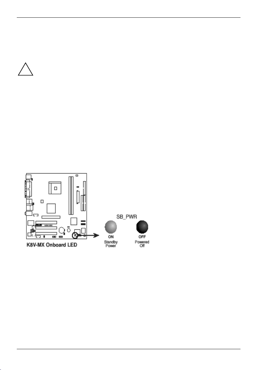
1.2.1 Onboard LED
The mainboard comes with a standby power LED. When lit, this green LED (SB_PWR) indicates
that the system is ON, in sleep mode, or in soft-off mode. This is a reminder that you should shut
down the system and unplug the power cable before removing or plugging in any mainboard
component.
● Unplug the power cord from the wall socket before touching any component.
!
● Discharge any static electricity by touching the metal surface of the system chassis.
● Hold components by the edges to avoid touching the ICs on them.
● Whenever you uninstall any component, place it on a grounded antistatic pad or in
the bag that came with the component.
● Before you install or remove any component, switch off the ATX power supply or
detach the power cord from the power supply. Failure to do so can cause severe
damage to the mainboard, peripherals, and/or components.
K8V-MX Onboard LED
8 A26361-D1711-Z120-1-7619, Edition 1
Page 17
1 Product introduction
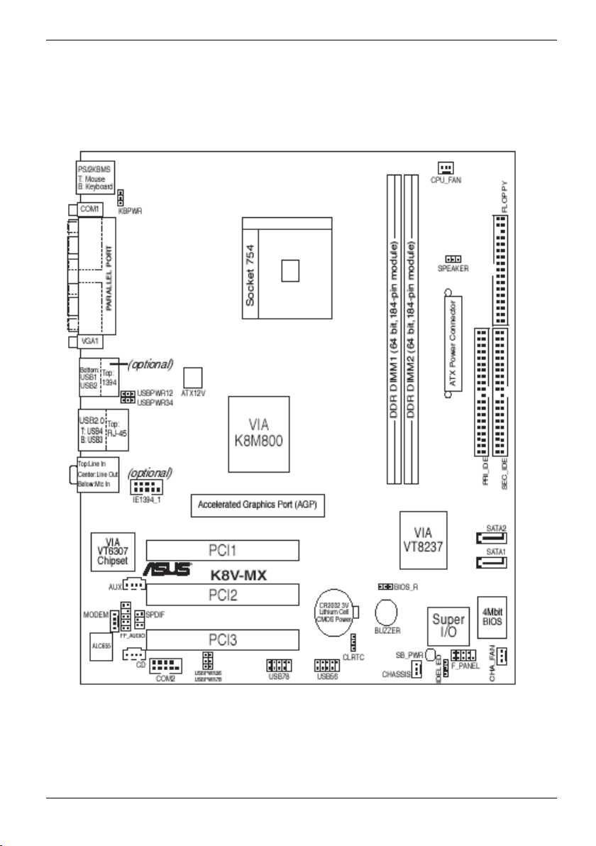
1.3 Mainboard overview
1.3.1 Mainboard layout
A26361-D1711-Z120-1-7619, Edition 1 9
Page 18
1 Product introduction
1.3.2 Placement direction
When installing the mainboard, make sure that you place it into the chassis in the correct
orientation. The edge with external ports goes to the rear part of the chassis as shown in the image
below.
1.3.3 Screw holes
Place nine screws into the holes indicated by circles to secure the mainboard to the chassis.
Do not overtighten the screws! Doing so can damage the mainboard.
!
1.4 Central Processing Unit (CPU)
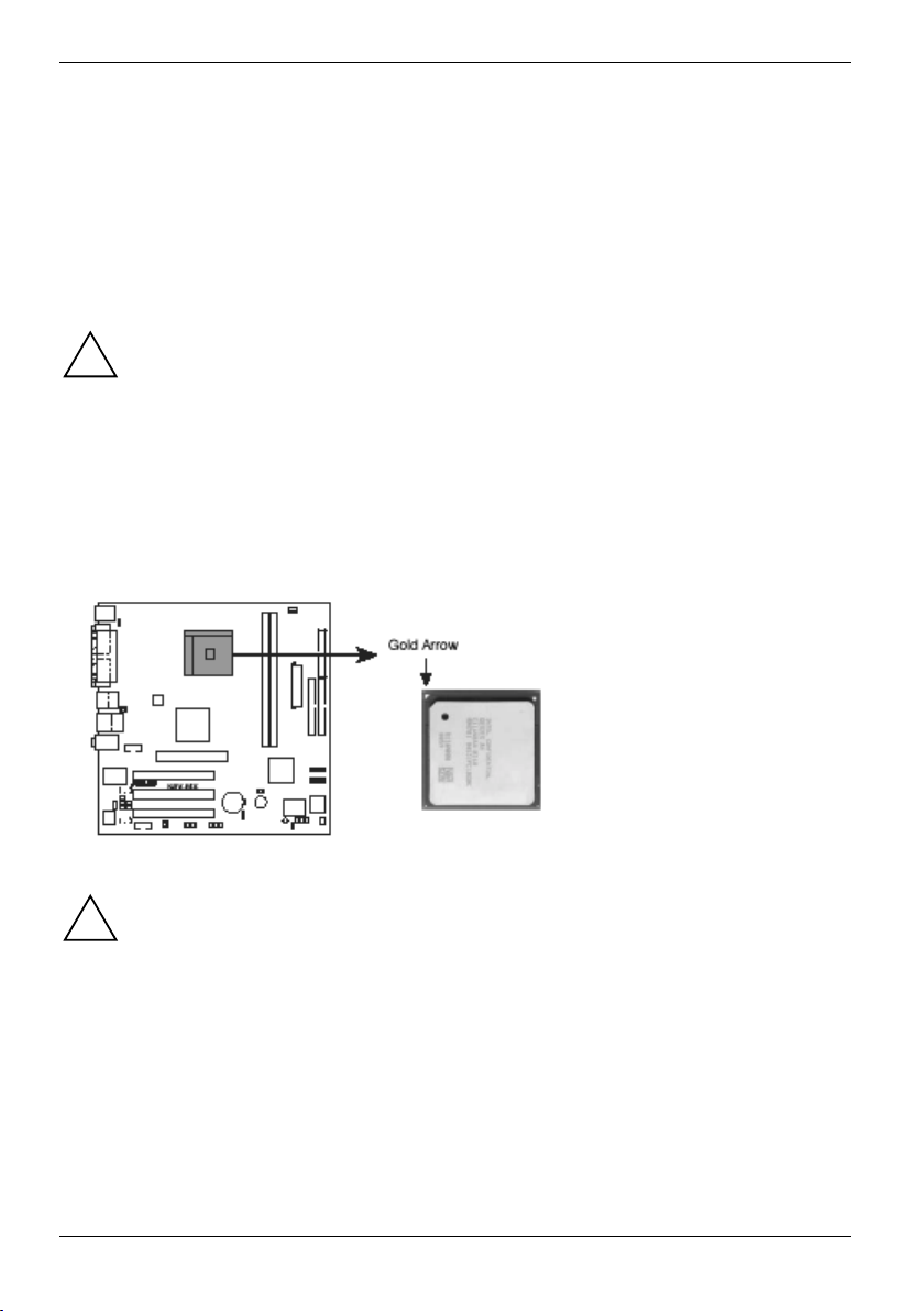
1.4.1 Overview
The AMD Athlon. 64 processor has a gold triangle in one corner. This mark indicates the processor
Pin A1 that should match a specific corner of the CPU socket.
K8V-MX Socket 754
10 A26361-D1711-Z120-1-7619, Edition 1
Incorrect installation of the CPU into the socket can bend the pins and severely damage
the CPU!
!
Page 19

1 Product introduction
1.4.2 Installing the CPU
Follow these steps to install a CPU.
1. Locate the 754-pin ZIF socket on the mainboard.
2. Unlock the socket by pressing the lever
sideways, then lift it up to a 90°-100° angle.
Make sure that the socket lever is lifted up
to 90°-100° angle, otherwise the CPU does
i
not fit in completely.
3. Position the CPU above the socket such
that the CPU corner with the gold triangle
matches the socket corner with a small
triangle.
4. Carefully insert the CPU into the socket
until it fits in place.
A26361-D1711-Z120-1-7619, Edition 1 11
The CPU fits only in one correct orientation. DO NOT force the CPU into the socket to
prevent bending the pins and damaging the CPU!
!
5. When the CPU is in place, push down the
socket lever to secure the CPU. The lever clicks
on the side tab to indicate that it is locked.
6. Install a CPU heatsink and fan following the
instructions that came with the heatsink
package.
7. Connect the CPU fan cable to the CPU_FAN
connector on the mainboard.
Page 20

1 Product introduction
1.5 System memory
1.5.1 Overview
The mainboard comes with two Double Data Rate (DDR) Dual Inline Memory Module (DIMM)
sockets. These sockets support up to 2 GB system memory using 184-pin PC3200/PC2700
unbuffered DDR DIMMs and allow up to 3.2 GB/s data transfer rate.
The following figure illustrates the location of the DDR DIMM sockets.
K8V-MX 184-Pin DDR DIMM Sockets
1.5.2 Memory configurations
You may install 64 MB, 128 MB, 256 MB, 512 MB, and 1 GB DDR DIMMs into the DIMM sockets.
12 A26361-D1711-Z120-1-7619, Edition 1
Page 21

1 Product introduction
1.5.3 Installing a DIMM
Unplug the power supply before adding or removing DIMMs or other system components
to prevent severe damage to the mainboard and the components.
!
Follow these steps to install a DIMM.
1. Locate the DIMM sockets in the mainboard.
2. Unlock a DIMM socket by pressing the
retaining clips outward.
3. Align a DIMM on the socket such that the
notch on the DIMM matches the break on the
socket.
A DDR DIMM is keyed with a notch so that it fits in only one direction. DO NOT force a
DIMM into a socket to avoid damaging the DIMM.
!
1.5.4 Removing a DIMM
4. Firmly insert the DIMM into the socket until the
retaining clips snap back in place and the DIMM
is properly seated.
Follow these steps to remove a DIMM.
1. Simultaneously press the retaining
clips outward to unlock the DIMM.
Support the DIMM lightly with your
fingers when pressing the retaining
!
clips. The DIMM might get damaged
when it flips out with extra force.
2. Remove the DIMM from the socket.
A26361-D1711-Z120-1-7619, Edition 1 13
Page 22

1 Product introduction
1.6 Expansion slots
The following sub-sections describe the mainboard slots and the expansion cards that they support.
1.6.1 Installing an expansion card
Follow these steps to install an expansion card.
1. Before installing the expansion card, read the documentation that came with it and make the
necessary hardware settings for the card.
2. Remove the system unit cover (if your mainboard is already installed in a chassis).
3. Remove the bracket opposite the slot that you intend to use. Keep the screw for later use.
4. Align the card connector with the slot and press firmly until the card is completely seated on the
slot.
5. Secure the card to the chassis with the screw you removed earlier.
6. Put back the system cover.
1.6.2 Configuring an expansion card
After installing the expansion card, configure the card by adjusting the software settings.
1. Turn on the system and change the necessary BIOS settings, if any. See Chapter 2 for
information on BIOS setup.
2. Install the software drivers for the expansion card.
Unplug the power cord before adding or removing expansion cards. Failure to do so can
cause you physical injury and damage mainboard components.
!
PCI Bus Interrupts for this mainboard
INT A INT B INT C INT D
PCI slot 1 shared
PCI slot 2 shared
PCI slot 3 shared
SATA shared
USB Shared (UHCI0-3) Shared (UHCI4-7) Shared (EHCI) Shared (Direct)
LAN shared
AGP slot shared
Onboard audio shared
14 A26361-D1711-Z120-1-7619, Edition 1
When using PCI cards on shared slots, ensure that the drivers support "Share IRQ" or
that the cards do not need IRQ assignments. Otherwise, conflicts will arise between the
i
two PCI groups, making the system unstable and the card inoperable. In this case try
another PCI Slot.
Page 23
1 Product introduction
1.6.3 PCI slots
The PCI slots support LAN, SCSI, USB, and
other PCI cards that comply with PCI
specifications. The figure below shows a LAN
card installed on a PCI slot.
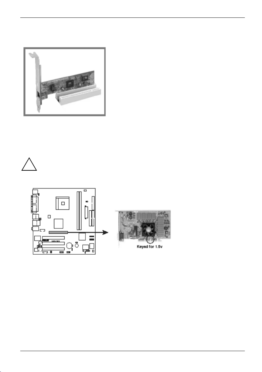
1.6.4 AGP slot
The Accelerated Graphics Port (AGP) slot supports AGP 8X (AGP 3.0) specification. Note the
notches on the card golden fingers to ensure that they fit the AGP slot on your mainboard.
Install only 1.5 V AGP cards on this mainboard! This mainboard does not support 3.3 V
AGP cards.
!
K8V-MX Accelerated Graphics Port (AGP)
A26361-D1711-Z120-1-7619, Edition 1 15
Page 24

1 Product introduction
1.7 Jumpers
1. Clear RTC RAM (CLRTC)
This jumper allows you to clear the Real Time Clock (RTC) RAM in CMOS. You can clear the
CMOS memory of date, time, and system setup parameters by erasing the CMOS RTC RAM data.
The onboard button cell battery powers the RAM data in CMOS, which include system setup
information such as system passwords.
To erase the RTC RAM:
1. Turn OFF the computer and unplug the power cord.
2. Move the jumper cap from pins 1-2 (default) to pins 2-3. Keep the cap on pins 2-3 for about 5~10
seconds, then move the cap back to pins 1-2.
3. Plug the power cord and turn ON the computer.
4. Hold down the Del key during the boot process and enter BIOS setup to re-enter data.
2. Keyboard power (3-pin KBPWR)
This jumper allows you to enable or disable the keyboard wake-up feature. Set this jumper to pins 23 (+5 VSB) to wake up the computer when you press a key on the keyboard (the default value is
[Disabled]). This feature requires an ATX power supply that can supply at least 1 A on the +5 VSB
lead, and a corresponding setting in the BIOS (see section "2.5.5 APM Configuration").
K8V-MX Keyboard Power Setting
16 A26361-D1711-Z120-1-7619, Edition 1
Page 25

1 Product introduction
3. USB device wake-up (3-pin USBPWR12, USBPWR34, USBPWR56, USBPWR78)
Set these jumpers to +5V to wake up the computer from S1 sleep mode (CPU stopped, DRAM
refreshed, system running in low power mode) using the connected USB devices. Set to +5VSB to
wake up from S3 sleep mode (no power to CPU, DRAM in slow refresh, power supply in reduced
power mode). All jumpers are set to pins 1-2 (+5V) by default because not all computers have the
appropriate power supply to support this feature.
The USBPWR12 and USBPWR34 jumpers are for the rear USB ports. The USBPWR56 and
USBPWR78 jumpers are for the internal USB header that you can connect to the front USB ports.
K8V-MX USB Device Wake Up
● The USB device wake-up feature requires a power supply that can provide 500mA
i
on the +5VSB lead for each USB port; otherwise, the system will not power up.
● The total current consumed must NOT exceed the power supply capability (+5VSB)
whether under normal condition or in sleep mode.
4. Force BIOS recovery (3-pin BIOS_R)
This jumper allows you to force recover the BIOS settings when the BIOS gets corrupted or
destroyed.
K8V-MX BIOS_R Setting
A26361-D1711-Z120-1-7619, Edition 1 17
Page 26

1 Product introduction
1.8 Connectors
This section describes and illustrates the rear panel and internal connectors on the mainboard.
1.8.1 Rear panel connectors
1. PS/2 mouse port
This green 6-pin connector is for a PS/2 mouse.
2. Parallel port
This 25-pin port connects a parallel printer, a scanner, or other devices.
3. IEEE 1394 port [not populated]
4. RJ-45 port
This port allows connection to a Local Area Network (LAN) through a network hub.
5. Line In port
This Line In (light blue) port connects a tape player or other audio sources. In 4- or 6-channel mode,
the function of this port becomes Rear Speaker Out.
6. Line Out port
This Line Out (lime) port connects a headphone or a speaker. In 4- or 6-channel mode, the function
of this port becomes Front Speaker Out.
18 A26361-D1711-Z120-1-7619, Edition 1
Page 27

1 Product introduction
7. Microphone port
This Mic (pink) port connects a microphone. In 6-channel mode, the function of this port becomes
Bass/Center Speaker.
Audio ports function variation
Audio ports Headphone /2-Channel 4-Channel 6-Channel
Light Blue Line In Rear Speaker Out Rear Speaker Out
Lime Line Out Front Speaker Out Front Speaker Out
Pink Mic In Mic In Bass/Center
8. USB 2.0 ports 3 and 4
These two 4-pin Universal Serial Bus (USB) ports are available for connecting USB 2.0 devices.
9. USB 2.0 ports 1 and 2
These two 4-pin Universal Serial Bus (USB) ports are available for connecting USB 2.0 devices
10. Video Graphics Adapter port
This 15-pin port is for a VGA monitor or other VGA-compatible devices.
11. Serial port
This 9-pin COM1 port is for pointing devices or other serial devices.
The functions of the Line Out, Line In, and Microphone ports change when you select the
4- or 6-channel audio configuration as shown in the following table.
i
12. PS/2 keyboard port
This purple connector is for a PS/2 keyboard.
1.8.2 Internal connectors
1. Floppy disk drive connector (34-1 pin FLOPPY)
This connector supports the provided floppy drive ribbon cable. Connect one end of the cable to the
mainboard, then connect the other end to the floppy drive.
(Pin 5 is removed to prevent incorrect insertion when using ribbon cables with Pin 5 plug).
A26361-D1711-Z120-1-7619, Edition 1 19
Page 28

1 Product introduction
K8V-MX Floppy Disk Drive Connector
2. Internal audio connectors (4-pin CD, AUX)
These connectors allow you to receive stereo audio input from sound sources such as a CD-ROM,
TV tuner, or MPEG card.
K8V-MX Internal Audio Connector
3. IDE connectors (40-1 pin PRI_IDE, SEC_IDE)
These connectors support the provided Ultra ATA133 IDE hard disk ribbon cable. Connect the
cable.s blue connector to the primary (recommended) or secondary IDE connector, then connect the
gray connector to the Ultra ATA133 slave device (hard disk drive) and the black connector to the
Ultra ATA133 master device. Connecting non-Ultra ATA133 devices to the secondary IDE connector
is recommended.
20 A26361-D1711-Z120-1-7619, Edition 1
Page 29

1 Product introduction
K8V-MX IDE Connectors
NOTE: Orient the red markings (usually zigzag) on the IDE ribbon cable to PIN 1.
● Pin 20 on each IDE connector is removed to match the covered hole on the Ultra
i
ATA cable connector. This prevents incorrect orientation when you connect the
cables.
● For Ultra ATA133 IDE devices, use an 80-conductor IDE cable.
● The hole near the blue connector on the Ultra ATA133 cable is intentional.
4. CPU and chassis fan connectors (3-pin CPU_FAN, CHA_FAN)
The fan connectors support cooling fans of 350mA~740mA (8.88W max.) or a total of 1 A~2.22 A
(26.64 W max.) at +12 V. Connect the fan cables to the fan connectors on the mainboard, making
sure that the black wire of each cable matches the ground pin of the connector.
Do not forget to connect the fan cables to the fan connectors. Insufficient air flow within
the system can damage the mainboard components. These are not jumpers! DO NOT
!
place jumper caps on the fan connectors!
K8V-MX 12-Volt Fan Connectors
A26361-D1711-Z120-1-7619, Edition 1 21
Page 30

1 Product introduction
5. ATX power connectors (20-pin ATXPWR, 4-pin ATX12V)
These connectors are for an ATX 12 V power supply. The plugs from the power supply are designed
to fit these connectors in only one orientation. Find the proper orientation and push down firmly until
the connectors fit completely.
In addition to the 20-pin ATXPWR connector, this mainboard requires that you connect the 4-pin
ATX +12 V power plug to provide sufficient power to the CPU.
K8V-MX ATX Power Connectors
● Do not forget to connect the 4-pin ATX +12 V power plug. Otherwise, the system
i
does not boot up.
● Make sure that your ATX 12 V power supply can provide 12 A on the +12 V lead and
at least 1 A on the +5-volt standby lead (+5 VSB). The system can become unstable
or will not boot up if the power is inadequate.
6. Front panel audio connector (10-1 pin FP_AUDIO)
This interface for the Intel® front panel audio cable allows convenient connection and control of
audio devices.
K8V-MX Front Panel Audio Connector
22 A26361-D1711-Z120-1-7619, Edition 1
Page 31

1 Product introduction
7. USB connectors (10-1 pin USB56, USB78)
If the USB ports on the rear panel are inadequate, a USB header is available for additional USB
ports. The USB header complies with USB 2.0 specification that supports up to 480 Mbps
connection speed. This speed advantage over the conventional 12 Mbps on USB 1.1 allows faster
Internet connection, interactive gaming, and simultaneous running of high-speed peripherals.
K8V-MX USB 2.0 Headers
NEVER connect a 1394 cable to the USB_56 or USB_78 connector. Doing so will damage
the mainboard!
!
The USB module is purchased separately.
i
A26361-D1711-Z120-1-7619, Edition 1 23
Page 32

1 Product introduction
8. System panel connector (10-1 pin F_PANEL)
This connector accommodates several system front panel functions.
K8V-MX F_Panel Connector
System Power LED Lead (2- pin PLED)
This connector is for the system power LED. The LED lights up when you turn on the system power,
and blinks when the system is in sleep mode.
ATX Power Switch / Soft-Off Switch Lead (2-pin PWRSW)
This connector is for a switch that controls the system power. Pressing the power switch turns the
system between ON and SLEEP, or ON and SOFT OFF, depending on the BIOS or OS settings.
Hard Disk Activity LED Lead (2- pin IDE_LED)
This connector supplies power to the hard disk activity LED. Any read or write activity of an IDE
device causes the LED to light up.
Reset Switch Lead (2-pin RESET)
This connector is for the case-mounted reset switch to reboot the system without turning off the
system power.
24 A26361-D1711-Z120-1-7619, Edition 1
Page 33

2 BIOS information
2 BIOS information
2.1 Managing and updating your BIOS
The AFUDOS utilitiy allows you to manage and update the mainboard Basic Input/Output System
(BIOS) setup.
2.1.1 Creating a bootable floppy disk
1. Do either one of the following to create a bootable floppy disk.
DOS environment
► Insert a 1.44 MB floppy disk into the drive.
► At the prompt, type:
Windows XP environment
► Insert a 1.44 MB floppy disk into the drive.
► From your Windows desktop, click on Start, the select My Computer.
► Select the 3 1/2 Floppy Drive icon.
► Click File from the menu, then select Format.
A Format 3 1/2 Floppy Drive window appears.
► Select Create an MS-DOS statup disk from the format options field, then click Start.
2. Copy the original (or the latest) mainboard BIOS to the bootable floppy disk.
Save a copy of the original mainboard BIOS file to a bootable floppy disk in case you
need to restore the BIOS in the future. Copy the original mainboard BIOS using the
i
AFUDOS utilitiy.
Format A:/s !
2.1.2 Using AFUDOS to copy the current BIOS
The AFUDOS utilitiy can also be used to copy the current system BIOS settings to a floppy or hard
disk. The copy can be used as a backup in case the system BIOS fails or gets corrupted.
1. At the DOS prompt, type the command line:
afudos /o [filename]
where filename can be any user-provided filename of not more than eight alphanumeric
characters for the main filename and three alphanumeric characters for the extension name.
Press ! .
A26361-D1711-Z120-1-7619, Edition 1 25
The BIOS information on the screen is for reference only. W hat you see on your screen
may not be exactly the same as shown.
i
Page 34

2 BIOS information
2. The utility will copy the current system BIOS by default to the floppy disk. Make sure that the
floppy disk is not write-protected and has enough space (at least 600 KB) to store the file.
When the BIOS copy process is complete, the utility returns to the prompt.
2.1.3 Using AFUDOS to update the BIOS
The AFUDOS utilitiy is a DOS-based application that lets you update the BIOS file using a bootable
floppy disk. AFUDOS also allows you to copy the original BIOS file to a floppy disk.
To update the BIOS using the AFUDOS utilitiy:
1. Download the latest BIOS file from the website provided by the system builder.
2. Copy the AFUDOS utilitiy from the support CD to the bootable floppy disk that contains the BIOS
file.
3. Boot the system from the floppy disk.
4. At the DOS prompt, type the command line:
5. Press ! .
The screen displays the status of the update process.
Write the BIOS filename on a piece of paper. You need to type the exact BIOS file name
at the prompt.
i
afudos /i [filename.rom]
where filename.rom means the latest (or original) BIOS file that you copied to the bootable
floppy disk.
The BIOS information on the screen is for reference only. W hat you see on your screen
may not be exactly the same as shown.
i
26 A26361-D1711-Z120-1-7619, Edition 1
Page 35

2 BIOS information
f
When the BIOS update process is complete, the utility returns to the prompt.
6. Reboot the system from the hard disk.
DO NOT shut down or reset the system while updating the BIOS! Doing so can cause
system boot failure.
!
2.1.4 Using ASUS EZ Flash to update the BIOS
The ASUS EZ Flash feature allows you to easily update the BIOS without having to go through the
long process of booting from a floppy disk and using a DOS-based utility. The EZ Flash is built-in the
BIOS LPC chip so it is accessible by simply pressing Alt + F2 during the Power-On Self Tests
(POST).
To update the BIOS using ASUS EZ Flash:
1. Visit the system builder website to download the latest BIOS file for your mainboard and rename it
to K8V-MX.ROM. Save the BIOS file to a floppy disk.
2. Reboot the system.
3. To launch EZ Flash, press Alt + F2 during POST to display the following.
A26361-D1711-Z120-1-7619, Edition 1 27
If there is no floppy disk in the drive, the error message Floppy not found! appears.
i
If the correct BIOS file is not found in the floppy disk, the error message K8VF.ROM not
ound! is displayed.
Page 36

2 BIOS information
4. Insert the floppy disk that contains the BIOS file. If the K8V-MX.ROM file is found in the floppy
disk, EZ Flash performs the BIOS update process and automatically reboots the system when done.
DO NOT shut down or reset the system while updating the BIOS! Doing so can cause
system boot failure!
!
2.1.5 Recovering the BIOS
This mainboard has a force recovery BIOS jumper (3-pin BIOS_R) that allows you to force recover
the BIOS settings when the BIOS gets corrupted or destroyed. The jumper block is on pins 1 and 2
during normal operation (default). To force recover the BIOS, set the jumper block on pins 2 and 3.
2.2 BIOS Setup program
This mainboard supports a programmable Low Pin Count (LPC) chip that you can update using the
provided utility described in section "2.1 Managing and updating your BIOS".
Use the BIOS Setup program when you are installing a mainboard, reconfiguring your system, or
prompted to "Run Setup". This section explains how to configure your system using this utility.
28 A26361-D1711-Z120-1-7619, Edition 1
The BIOS software is constantly being updated so the BIOS setup screens and
descriptions in this section are for reference only, and may not be exactly match what you
i
see on your screen.
Page 37

2 BIOS information
Even if you are not prompted to use the Setup program, you can change the configuration of your
computer in the future. For exampla, you can enable the security password feature or make
changes to the power management settings. This requires you to reconfigure your system using the
BIOS Setup program so that the computer can recognize these changes and record them in the
CMOS RAM of the LPC chip.
The LPC chip on the mainboard stores the Setup utility. When you start up the computer, the
system provides you with the opportunity to run this program. Press Del during the Power-On Self
Test (POST) to enter the Setup utility; otherwise, POST continues with ist test routines.
To enter Setup after POST, restart the system by pressing Ctrl + Al t + Del . You can also
restart by turning the system off and then back on. Do this last option only when the first fails.
The Setup program is designed to make it as easy to use as possible. Being a menu-driven
program, it lets you scroll through the various sub-menus and make your selections among the
predertermined choices.
2.2.1 BIOS menu screen
2.2.2 Menu bar
The menu bar on top of the screen has the following main items:
Main For changing the basic system configuration
Advanced For changing the advanced system settings
Power For changing the advanced power management (APM) configuration
Boot For changing the system boot configuration
Exit For selecting the exit options and loading default settings
To select an item on the menu bar, press the right or left arrow key on the keyboard until the desired
item is highlighted.
A26361-D1711-Z120-1-7619, Edition 1 29
Page 38

2 BIOS information
2.2.3 Navigation keys
At the bottom right corner of a menu screen are the navigation keys for that particular menu. Use
the navigation keys to select items in the menu and change the settings.
Some of the navigation keys differ from one screen to another.
i
2.2.4 Menu items
The highlighted item on the menu bar displays
the specific items for that menus. For example,
selecting Main shows the Main menu items.
The other items (Advanced, Power, Boot, and
Exit) on the menu bar have theit respective
menu items.
Main menu items
2.2.5 Configuration fields
These fields show the values for the menu items. If an item is user-configurable, you can change
the value of the field opposite the item. You cannot select an item that is not user-configurable.
A configurable field is enclosed in brackets, and is highlighted when selected. To change the value
of a field, select it then press ! to display a list of options.
2.2.6 Pop-up window
Select a menu item then press ! to display a pop-up window with the configuration options for that
item.
2.2.7 Scroll bar
A scroll bar appears on the right side of a menu
screen when there are items that do not fit on
the screen. Press the " / # keys to display
the other items on the screen.
30 A26361-D1711-Z120-1-7619, Edition 1
Page 39

2 BIOS information
2.2.8 General help
At the top right corner of the menu screen is a brief description of the selected item
2.3 Main menu
When you enter the BIOS Setup program, the Main menu screen appears, giving you an overview of
the basic system information.
Refer to section "2.2.1 BIOS menu screen" for information on the menu screen items and
how to navigate through them.
i
2.3.1 System Time [xx:xx:xxxx]
Allows you to set the system time.
2.3.2 System Date [Day xx/xx/xxxx]
Allows you to set the system date.
2.3.3 Legacy Diskette A [1.44M, 3.5 in.]
Sets the type of floppy drive installed. Configuration options: [Disabled] [360K, 5.25 in.]
[1.2M , 5.25 in.] [720K , 3.5 in.] [1.44M, 3.5 in.] [2.88M, 3.5_in.]
2.3.4 Primary/Secondary IDE Master/Slave
While entering Setup, BIOS automatically detects the presence of IDE devices. There is a separate
sub-menu for each IDE device. Select a device item then press ! to display the IDE device
information.
A26361-D1711-Z120-1-7619, Edition 1 31
Page 40

2 BIOS information
The BIOS automatically detects the values opposite the dimmed items (Device, Vendor, Size, LBA
Mode, Block Mode, PIO Mode, Async DMA, Ultra DMA, and SMART monitoring). These values are
not user-configurable. These items show N/A if no IDE device is installed in the system.
Type [Auto]
Selects the type of IDE drive.
Configuration options: [Auto] [Not Installed] [CDROM] [ARMD]
LBA/Large Mode [Auto]
Enables or disables the LBA mode. Setting to Auto enables the LBA mode if the device supports this
mode, and if the device was not previously formatted with LBA mode disabled.
Configuration options: [Auto] [Disabled]
Block (Multi-Sector Transfer) [Auto]
Enables or disables data multi-sectors transfers. When set to Auto, the data transfer from and to the
device occurs multiple sectors at a time if the device supports multi-sector transfer feature. When
set to Disabled, the data transfer from and to the device occurs one sector at a time.
Configuration options: [Auto] [Disabled]
PIO Mode [Auto]
Selects the PIO mode.
Configuration options: [Auto] [0] [1] [2] [3] [4]
DMA Mode [Auto]
Selects the DMA mode.
Configuration options: [Auto] [SWDMA0] [SWDMA1] [SWDMA2] [MWDMA0] [MW DMA1]
[MWDMA2] [UDMA0] [UDMA1] [UDMA2] [UDMA3] [UDMA4] [UDMA5] [UDMA6]
SMART Monitoring [Auto]
Sets the Smart Monitoring, Analysis, and Reporting Technology.
Configuration options: [Auto] [Disabled] [Enabled]
32 A26361-D1711-Z120-1-7619, Edition 1
Page 41

2 BIOS information
32Bit Data Transfer [Disabled]
Enables or disables 32-bit data transfer.
Configuration options: [Disabled] [Enabled]
Acoustics [Maximum Performance]
Sets the level of acoustic management on the hard drive.
Configuration options: [Maximum Performance] [Silent] [Medium]
2.3.5 System Information
This menu gives you an overview of the general system specifications. The items in this menu are
auto-detected by the BIOS.
AMI BI OS
Displays the auto-detected BIOS information.
System Memory
Displays the auto-detected system memory.
A26361-D1711-Z120-1-7619, Edition 1 33
Page 42

2 BIOS information
2.4 Advanced menu
The Advanced menu items allow you to change the settings for the CPU and other system devices.
2.4.1 CPU Configuration
The items in this menu show the CPU-related information that the BIOS automatically detects.
Take caution when changing the settings of the Advanced menu items. Incorrect field
values can cause the system to malfunction.
!
Memory Configuration
34 A26361-D1711-Z120-1-7619, Edition 1
Page 43

2 BIOS information
Memory Configuration
Memclock Mode [Auto]
Bank Interleaving [Disabled]
CAS Latency (CL) [Auto]
TRCD [Auto]
TRAS [Auto]
TRP [Auto]
Allows you to set the memory clock mode. Set by the code using [Auto] or select
[Manual] to set using one of the standard values.
Configuration options: [Auto] [Limit]
Sets whether to allow memory accesses to be spread out over BANKS on the same
node or across nodes, decreasing access contention.
Configuration options: [Auto] [Disabled]
Sets the CAS Latency. Configuration options: [Auto] [2.0] [3.0] [2.5]
Sets the TRCD. Configuration options: [Auto] [2 CLK] [3 CLK] [4 CLK] [5 CLK]
[6 CLK]
Sets the TRAS. Configuration options: [Auto] [5 CLK] [6 CLK] [7 CLK] [8 CLK]
[9 CLK] [10 CLK] [11 CLK] [12 CLK] [13 CLK] [14 CLK] [15 CLK]
Sets the TRP. Configuration options: [Auto] [2 CLK] [3 CLK] [4 CLK] [5 CLK] [6 CLK]
AMD Cool & Quiet Configuration
Cool N’ Quiet [Enabled]
Allows you to enable or disable the AMD K8 Cool‘n’Quiet function.
Configuration options: [Enabled] [Disabled]
A26361-D1711-Z120-1-7619, Edition 1 35
Page 44

2 BIOS information
2.4.2 Chipset
The Chipset menu allows you to change the advanced chipset settings. Select an item then press
! to display the sub-menu.
AGP Bridge Configuration
CPU Direct Access OnChip VGA F [Disabled]
Enables or disables the CPU direct frame buffer.
Configuration options: [Disabled] [Enabled]
OnChip VGA Frame Buffer Size [64MB]
Sets the size of the main memory shared as video RAM
Configuration options: [8MB] [16MB] [32MB] [64MB]
Dithering [Disabled]
Enables or disables support for 18-bit LCD panel to 24-bit color depth under different resolutions.
Configuration options: [Disabled] [Enabled]
Primary Graphics Adapter [AGP]
Switches the PCI Bus scanning order while searching for a video card. This allows you to select the
type of Primary VGA in case of multiple video controllers.
Configuration options: [AGP] [PCI]
36 A26361-D1711-Z120-1-7619, Edition 1
Page 45

2 BIOS information
Search for MDA Resources [No]
Sets whether to allow search for MDA resources.
Configuration options: [No] [Yes]
VLink 8X Supported [Enabled]
Enables or Disables support for VLink, which is a VIA-dedicated bus. The data transfer rate
supports VLink 4X and VLink 8X.
Configuration options: [Disabled] [Enabled]
AGP Mode [AGP 8X]
This mainboard supports the AGP 8X interface that transfers video data at 2.12 GB/s. AGP 8X is
backward-compatible, so you can keep the default [AGP 4X] mode even if you are using an AGP 8X
video card. When set to [AGP 4X] mode, the AGP interface only provides a peak data throughput of
1.06 GB/s even if you are using an AGP 8X video card.
Configuration options: [AGP 8X] [AGP 4X] [AGP 2X] [AGP 1X]
The [AGP 8X] option appears only when you install an AGP 8X graphics card.
i
AGP Fast Write [Enabled]
Enables or disables the AGP Fast Write feature.
Configuration options: [Enabled] [Disabled]
Graphics Aperture Size [64MB]
Allows you to select the size of mapped memory for AGP graphic data.
Configuration options: [256MB] [128MB] [64MB] [32MB]
AGP 3.0 Calibration cycle [Disabled]
Enables or disables the AGP Calibration mechanism.
Configuration options: [Disabled] [Enabled]
DBI Output for AGP Trans [Disabled]
Enables or disables the DBI output for AGP Trans.
Configuration options: [Disabled] [Enabled]
SouthBridge Configuration
MPS Revision [1.4]
Sets the MPS revision value. Configuration options: [1.1] [1.4]
A26361-D1711-Z120-1-7619, Edition 1 37
Page 46

2 BIOS information
PCI Delay Transaction [Disabled]
Enables or disables the PCI delay transaction feature.
Configuration options: [Disabled] [Enabled]
USB Configuration
USB 1.1 Ports Configuration [USB 8 Ports]
Allows you to set the number of USB ports to activate.
Configuration options: [Disabled] [USB 2 Ports] [USB 4 Ports] [USB 6 Ports] [USB 8 Ports]
USB 2.0 Controller [Enabled]
Allows you to enable or disable the USB 2.0 controller.
Configuration options: [Enabled] [Disabled]
Legacy USB Support [Auto]
Allows you to enable or disable support for legacy USB devices. Setting to Auto allows the system
to detect the presence of USB devices at startup. If detected, the USB controller legacy mode is
enabled. If no USB device is detected, the legacy USB support is disabled.
Configuration options: [Auto] [Disabled] [Enabled]
USB 2.0 Controller Mode [HiSpeed]
Allows you to configure the USB 2.0 controller to HiSpeed (480 Mbps) or FullSpeed (12 Mbps).
Configuration options: [HiSpeed] [FullSpeed]
The Module Version and USB Devices Enabled items show the auto-detected
values. If no USB device is detected, the item shows None.
i
38 A26361-D1711-Z120-1-7619, Edition 1
Page 47

2 BIOS information
2.4.3 Onboard Devices Configuration
Floppy Disk Controller [Enabled]
Enables or disables the Floppy Disk Controller.
Configuration options: [Enabled] [Disabled]
Onboard PCI IDE Controller [Both]
Setting this item to [Primary] enables the Primary IDE controller. Setting to [Secondary] enables the
Secondary IDE controller. Setting to [Both] enables both IDE controllers. Setting to [Disabled]
disables the integrated IDE controller.
Configuration options: [Primary] [Secondary] [Both] [Disabled]
Disabling the Onboard PCI IDE Controller disables the Serial ATA function, too.
i
OnBoard AC.97 Audio [Enabled]
Selecting [Enabled] allows the BIOS to detect whether you are using any audio device. If an audio
device is detected, the onboard audio controller is enabled. If no audio device is detected, the
controller is disabled.
Configuration options: [Enabled] [Disabled]
OnChip SATA BOOTROM [Enabled]
Enables or disables the Serial ATA Boot ROM.
Configuration options: [Enabled] [Disabled]
A26361-D1711-Z120-1-7619, Edition 1 39
Page 48

2 BIOS information
OnBoard LAN [Enabled]
Allows you to enable or disable the onboard LAN controller.
Configuration options: [Enabled] [Disabled]
OnBoard LAN Boot ROM [Enabled]
Allows you to enable or disable the onboard LAN Boot ROM.
Configuration options: [Disabled] [Enabled]
Serial Port1 Address [3F8/IRQ4]
Allows you to select the Serial Port1 base address.
Configuration options: [Disabled] [3F8/IRQ4] [3E8/IRQ4] [2E8/IRQ3]
Serial Port2 Address [2F8/IRQ3]
Allows you to select the Serial Port2 base address.
Configuration options: [Disabled] [2F8/IRQ3] [3E8/IRQ4] [2E8/IRQ3]
Parallel Port Address [378]
Allows you to select the Parallel port base addresses.
Configuration options: [Disabled] [378] [278] [3BC]
Parallel Port Mode [ECP]
Allows you to select the Parallel port mode.
Configuration options: [Normal] [Bi-Directional] [EPP] [ECP]
ECP Mode DMA Channel [DMA3]
Appears only when the Parallel Port Mode is set to [ECP] and allows you to set the Parallel Port
ECP DMA.
Configuration options: [DMA0] [DMA1] [DMA3]
EPP Version [1.9]
Appears only when the Parallel Port Mode is set to [EPP] and allows you to select the Parallel Port
EPP version.
Configuration options: [1.9] [1.7]
Parallel Port IRQ [IRQ7]
Allows you to select the Parallel Port IRQ.
Configuration options: [IRQ5] [IRQ7]
40 A26361-D1711-Z120-1-7619, Edition 1
Page 49

2 BIOS information
2.4.4 PCI PnP
The PCI PnP menu items allow you to change the advanced settings for PCI/PnP devices. The
menu includes setting IRQ and DMA channel resources for either PCI/PnP or legacy ISA devices.
Take caution when changing the settings of the PCIPnP menu items. Incorrect field
values can cause the system to malfunction.
!
Plug And Play O/S [Yes]
When set to [No], BIOS configures all the devices in the system. When set to [Yes] and if you
installed a Plug and Play operating system, the operating system configures the Plug and Play
devices not required for boot.
Configuration options: [Yes] [No]
PCI Latency Timer [64]
Allows you to select the value in units of PCI clocks for the PCI device latency timer register.
Configuration options: [32] [64] [96] [128] [160] [192] [224] [248]
Allocate IRQ to PCI VGA [Yes]
When set to [Yes], BIOS assigns an IRQ to PCI VGA card if the card requests for an IRQ. When set
to [No], BIOS does not assign an IRQ to the PCI VGA card even if requested.
Configuration options: [No] [Yes]
A26361-D1711-Z120-1-7619, Edition 1 41
Page 50

2 BIOS information
Palette Snooping [Disabled]
When set to [Enabled], the palette snooping feature informs the PCI devices that an ISA graphics
device is installed in the system so that the latter can function correctly.
Configuration options: [Disabled] [Enabled]
IRQ xx [Available]
When set to [Available], the specific IRQ is free for use of PCI/PnP devices. When set to
[Reserved], the IRQ is reserved for legacy ISA devices.
Configuration options: [Available] [Reserved]
2.5 Power menu
The Power menu items allow you to change the power settings. Select an item then press ! to
display the configuration options.
2.5.1 Suspend Mode [S1 & S3 Auto]
Allows you to select the ACPI state to be used for system suspend.
Configuration options: [S1 Only] [S3 Only] [S1 & S3 Auto]
2.5.2 Repost Video on S3 Resume [No]
Determines whether to invoke VGA BIOS POST on S3/STR resume.
Configuration options: [No] [Yes]
2.5.3 ACPI 2.0 Support [No]
Allows you to add more tables for ACPI 2.0 specifications.
Configuration options: [No] [Yes]
42 A26361-D1711-Z120-1-7619, Edition 1
Page 51

2 BIOS information
2.5.4 ACPI APIC Support [Enabled]
Enables or disables the ACPI support in the ASIC. When set to Enabled, the ACPI APIC table
pointer is included in the RSDT pointer list.
Configuration options: [Disabled] [Enabled]
2.5.5 APM Configuration
Power Management/APM [Enabled]
Allows you to enable or disable the Advanced Power Management (APM) feature.
Configuration options: [Disabled] [Enabled]
The following items appear only when the Power Management/APM item is set to
[Enabled].
i
Power Button Mode [On/Off]
Allows the system to go into On/Off mode or suspend mode when the power button is pressed.
Configuration options: [On/Off] [Suspend]
Suspend Power Saving Type [C3]
Allows you to set the suspend power saving type.
Configuration options: [C3] [S1]
A26361-D1711-Z120-1-7619, Edition 1 43
Page 52

2 BIOS information
Restore on AC Power Loss [Last State]
When set to Power Off, the system goes into off state after an AC power loss. W hen set to Power
On, the system goes on after an AC power loss. When set to Last State, the system goes into either
off or on state whatever was the system state before the AC power loss.
Configuration options: [Last State] [Power Off] [Power On]
Suspend Time Out [Disabled]
Allows you to select the specified time at which the system goes on suspend mode.
Configuration options: [Disabled] [1 Minute] [2 Minutes] [4 Minutes] [8 Minutes] [10 Minutes]
[20 Minutes] [30 Minutes] [40 Minutes] [50 Minutes] [60 Minutes]
Power On By RTC Alarm [Disabled]
Allows you to enable or disable RTC to generate a wake event. When this item is set to Enabled,
the items RTC Alarm Date, RTC Alarm Hour, RTC Alarm Minute, and RTC Alarm Second appear
with set values.
Configuration options: [Disabled] [Enabled]
Power On External Modems [Disabled]
Allows either settings of [Enabled] or [Disabled] for powering up the computer when the external
modem receives a call while the computer is in Soft-off mode.
Configuration options: [Disabled] [Enabled]
The computer cannot receive or transmit data until the computer and applications are fully
running. Thus, connection cannot be made on the first try.
i
Turning an external modem off and then back on while the computer is off causes an
initialization string that turns the system power on.
Power On PCI Device [Enabled]
When set to [Enabled], this parameter allows you to turn on the system through a PCI LAN or
modem card. This feature requires an ATX power supply that provides at least 1 A on the +5 VSB
lead.
Configuration options: [Enabled] [Disabled]
Power On PS/2 KeyBoard [Disabled]
Allows you to use specific keys on the keyboard to turn on the system. When set to [S5], the item
Wake-up Key is enabled. This feature requires an ATX power supply that provides at least 1 A on
the +5V SB lead.
Configuration options: [Disabled] [Enabled]
44 A26361-D1711-Z120-1-7619, Edition 1
Page 53

2 BIOS information
Power On PS/2 Mouse [Disabled]
When set to [Enabled], this parameter allows you to use the PS/2 mouse to resume the system.
This feature requires an ATX power supply that provides at least 1 A on the +5 VSB lead.
Configuration options: [Disabled] [Enabled]
Power On OnBoard LAN [Enabled]
When set to [Enabled], this option allows you to use the onboard LAN to turn on the system.
Configuration options: [Enabled] [Disabled]
2.5.6 Hardware Monitor
CPU Temperature [xxx°C/xxx°F] MB Temperature [xxx°C/xxx°F]
The onboard hardware monitor automatically detects and displays the CPU and mainboard
temperatures.
CPU Fan Speed [Ignored] Chassis Fan Speed [Ignored]
The onboard hardware monitor automatically detects and displays the CPU and chassis fan speeds
in rotations per minute (RPM). If any of the fans is not connected to the mainboard, the specific field
shows N/A.
Configuration options: [Ignored] [xxxxRPM] [N/A]
A26361-D1711-Z120-1-7619, Edition 1 45
Page 54

2 BIOS information
VCORE Voltage, 3.3V Voltage, 5V Voltage, 12V Voltage
The onboard hardware monitor automatically detects the voltage output through the onboard voltage
regulators.
If any of the monitored items is out of range, the following error message appears:
i
Hardware Monitor found an error. Enter Power setup menu for
details
You will then be prompted to:
Press F1 to continue or DEL to enter SETUP
2.6 Boot menu
The Boot menu items allow you to change the system boot options. Select an item then press ! to
display the sub-menu.
2.6.1 Boot Device Priority
46 A26361-D1711-Z120-1-7619, Edition 1
Page 55

2 BIOS information
1st ~ xxth Boot Device [1st FLOPPY DRIVE]
These items specify the boot device priority sequence from the available devices. The number of
device items that appear on the screen depends on the number of devices installed in the system.
Configuration options: [xxxxx Drive] [Disabled]
2.6.2 Boot Settings Configuration
Quick Boot [Enabled]
Enabling this item allows BIOS to skip some power on self tests (POST) while booting to decrease
the time needed to boot the system. When set to [Disabled], BIOS performs all the POST items.
Configuration options: [Enabled] [Disabled]
Full Screen Logo [Enabled]
Allows you to enable or disable the full screen logo display feature.
Configuration options: [Enabled] [Disabled]
AddOn ROM Display Mode [Force BIOS]
Sets the display mode for option ROM.
Configuration options: [Force BIOS] [Keep Current]
Bootup Num-Lock [On]
Allows you to select the power-on state for the NumLock.
Configuration options: [On] [Off]
A26361-D1711-Z120-1-7619, Edition 1 47
Page 56

2 BIOS information
PS/2 Mouse Support [Auto]
Allows you to enable or disable support for PS/2 mouse.
Configuration options: [Auto] [Disabled] [Enabled]
Wait for "F1" If Error [Enabled]
When set to [Enabled], the system waits for F1 key to be pressed when error occurs.
Configuration options: [Enabled] [Disabled]
Hit "DEL" Message Display [Enabled]
When set to [Enabled], the system displays the message Press DEL to run Setup during POST.
Configuration options: [Enabled] [Disabled]
Interrupt 19 Capture [Disabled]
When set to [Enabled], this function allows the option ROMs to trap Interrupt 19.
Configuration options: [Disabled] [Enabled]
F12 Boot Menu [Enabled]
When set to [Enabled] and F12 is pressed, this item opens the Boot menu.
Configuration options: [Disabled] [Enabled]
2.6.3 Security
The Security menu items allow you to change the system security settings. Select an item then press
! to display the configuration options.
48 A26361-D1711-Z120-1-7619, Edition 1
Page 57

2 BIOS information
Change Supervisor Password
Select this item to set or change the supervisor password. The Supervisor Password item on top of
the screen shows the default Not Installed. After you have set a password, this item shows Installed.
To set a Supervisor Password:
1. Select the Change Supervisor Password item and press ! .
2. On the password box that appears, type a password composed of at least six letters and/or
numbers, then press ! .
3. Confirm the password when prompted.
The message Password Installed appears after you successfully set your password. The Supervisor
Password item now shows Installed. To change the supervisor password, follow the same steps as in
setting a user password.
To clear the supervisor password, select the Change Supervisor Password, then press ! . The
message Password Uninstalled appears.
After you set a supervisor password, the other items appear to allow you to change other security
settings.
User Access Level (Full Access]
Allows you to select the access restriction to the Setup items.
Configuration options: [No Access] [View Only] [Limited] [Full Access]
No Access prevents user access to the Setup utility.
View Only allows access but does not allow change to any field.
Limited allows change to only selected fields, such as Date and Time.
Full Access allows viewing and changing all the fields in the Setup utility.
A26361-D1711-Z120-1-7619, Edition 1 49
Page 58

2 BIOS information
Change User Password
Select this item to set or change the user password. The User Password item on top of the screen
shows the default Not Installed. After you have set a password, this item shows Installed.
To set a User Password:
1. Select the Change User Password item and press ! .
2. On the password box that appears, type a password composed of letters and/or numbers, then
press ! . Your password should have at least six characters.
3. Confirm the password when prompted.
The message Password Installed appears after you have successfully set your password. The User
Password item now shows Installed. To change the user password, follow the same steps as in
setting a user password.
Password Check [Setup]
Allows you to select the access restriction to setup or even boot the system.
Configuration options: [Setup] [Always]
Boot Sector Virus Protection [Disabled]
Enables or disables Boot Sector Virus Protection.
Configuration options: [Disabled] [Enabled]
Chassis Intrusion [Disabled]
Enables or disables checking of Chassis Intrusion.
Configuration options: [Disabled] [Enabled]
Flash Write Protection [Disabled]
Enables or disables Flash W rite Protection.
Configuration options: [Enabled] [Disabled]
50 A26361-D1711-Z120-1-7619, Edition 1
Page 59

2 BIOS information
2.7 Exit menu
The Exit menu items allow you to load the optimal or failsafe default values for the BIOS items, and
save or discard your changes to the BIOS items.
Pressing Esc does not immediately exit this menu. Select one of the options from this
menu or F10 from the legend bar to exit.
i
Exit & Save Changes
Once you are finished making your selections, choose this option from the Exit menu to ensure the
values you selected are saved to the CMOS RAM. The CMOS RAM is sustained by an onboard
backup battery and stays on even when the PC is turned off. When you select this option, a
confirmation window appears. Select Yes to save changes and exit.
If you attempt to exit the Setup program without saving your changes, the program
prompts you with a message asking if you want to save your changes before exiting.
i
Pressing ! saves the changes while exiting.
Exit & Discard Changes
Select this option only if you do not want to save the changes that you made to the Setup program.
If you made changes to fields other than system date, system time, and password, the BIOS asks
for a confirmation before exiting.
A26361-D1711-Z120-1-7619, Edition 1 51
Page 60

2 BIOS information
Discard Changes
This option allows you to discard the selections you made and restore the previously saved values.
After selecting this option, a confirmation appears. Select Yes to discard any changes and load the
previously saved values.
Load Setup Defaults
This option allows you to load the default values for each of the parameters on the Setup menus.
When you select this option, or if you press F5 , a confirmation window appears. Select Yes to load
the default values. Select Exit & Save Changes or make other changes before saving the values to
the non-volatile RAM.
52 A26361-D1711-Z120-1-7619, Edition 1
 Loading...