

Page 1

answers
Mainboard D1596-A
(GA-7VKMP-FA Rev 5.x)
English
2
Technical Manual
Page 2

Are there ...
... any technical problems or other questions you need clarified?
Please contact:
• your sales partner
• your sales outlet
The latest information and updates (e. g. BIOS update) on our mainboards c an be found on the
Internet under: http://www.fujitsu-siemens.com
Page 3

Page 4

Dieses Handbuch wurde auf Recycling-Papier gedruckt.
This manual has been printed on recycled paper.
Ce manuel est imprimé sur du papier recyclé.
Este manual ha sido impreso sobre papel reciclado.
Questo manuale è stato stampato su carta da riciclaggio.
Denna handbok är tryckt på recyclingpapper.
Dit handboek werd op recycling-papier gedrukt.
Herausgegeben von/Published by
Fujitsu Siemens Computers GmbH
Bestell-Nr./Order No.:
Printed in the Federal Republic of Germany
AG 0503 05/03
A26361-D1596-Z121-1-7619
A26361-D1596-Z121-1-7619
Page 5

Mainboard D1596-A
(GA-7VKMP-FA Rev 5.x)
Technical Manual
English
May 2003 edition
Page 6

Microsoft, MS, MS-DOS and Windows are registered trademarks of Microsoft Corporation.
PS/2 and OS/2 Warp are registered tradem arks of International Busi ness Machines, Inc.
All other trademarks referenced are trademarks or registered trademarks of their respectiv e
owners, whose protected rights are acknowledged.
All rights, includi ng ri ghts of translation, reproduction by printing, copying or s i m i l ar methods,
even of parts are reserved.
Offenders will be liable for damages.
All rights, including rights creat ed by patent grant or registration of a utilit y model or design,
are reserved. Delivery subject to availability.
Right of technical modi f i cation reserved.
This manual was produced by
cognitas. Gesellschaft für Technik-Dokumentation mbH
www.cognitas.de
Page 7
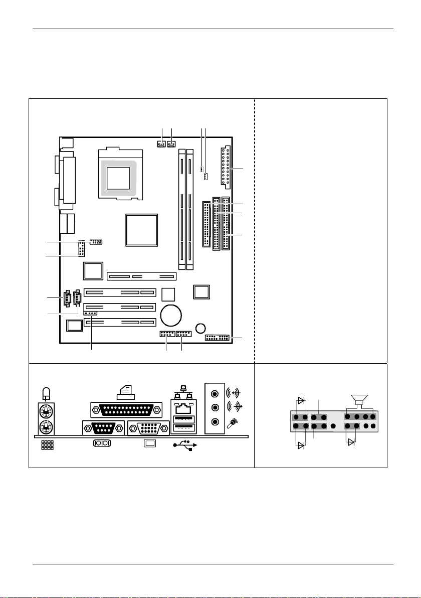
Overview Mainboard D1596-A (GA-7VKMP-FA Rev 5.x)
Internal connectors and slots
13 15
14 16
1 = Power Supply (ATX)
2 = Floppy disk drive
3 = Primary IDE
4 = Secondary IDE
5 = Front panel
6 = F_USB2
7 = F_USB1
Socket A
DDR 1
DDR 2
1
8 = IR
9 = AUX_IN
10 = CD_IN
2
11 = F_AUDIO
3
12 = COMB
13 = CPU_FAN
14 = SYS_FAN
12
11
10
AGP
PCI 1
9
PCI 2
PCI 3
BIOS
Battery
Buzzer
4
15 = RAM_LED
16 = CLK_JP (Jumper)
5
8
7
6
External connectors Front panel
Power On LED
+
Power On/Off
Speaker
+
Reset
HD-LED
A26361-D1596-Z121-1-7619 Umschlag/Cover
+
Sleep LED
Page 8

Page 9

Contents
Overview Mainboard D1596-A (GA-7VKMP-FA Rev 5.x)................................................................1
Mainboard D1596-A (GA-7VKMP-FA Rev 5.x)...............................................................................1
Notational conventions ..............................................................................................................1
Important notes..................................................................................................................................2
Information about mainboards ...................................................................................................2
List of features...................................................................................................................................3
Interfaces and connectors..............................................................................................................4
External ports....................................................................................................................................4
Internal ports and connectors ............................................................................................................5
Hard disk connection.................................................................................................................5
Pin assignment of internal ports.........................................................................................................6
Settings with jumpers.......................................................................................................... ...........9
CPU Speed Setup.............................................................................................................................9
Add-on modules / Upgrading........................................................................................................10
Installing and removing processors..................................................................................................10
Installing the processor with heat sink and fan.........................................................................10
Upgrading main memory..........................................................................................................12
Upgrading AGP screen controllers...................................................................................................14
Adding PCI cards.............................................................................................................................15
PCI bus interrupts - Selecting correct PCI slot.........................................................................15
Replacing lithium battery..........................................................................................................16
BIOS Setup.....................................................................................................................................17
Entering Setup.................................................................................................................................17
Getting Help....................................................................................................................................18
The Main Menu (For example: BIOS Ver. : F1h)..............................................................................18
Standard CMOS Features ...............................................................................................................20
BIOS Features Setup......................................................................................................................23
Chipset Features Setup...................................................................................................................25
Power Management Setup ..............................................................................................................28
PNP/PCI Configuration....................................................................................................................31
Load Fail-Safe Defaults...................................................................................................................33
Load Optimized Defaults .................................................................................................................34
Integrated Peripherals .....................................................................................................................35
Hardware Monitor & MISC Setup.....................................................................................................38
Set Supervisor / User Password ......................................................................................................39
IDE HDD Auto Detecti o n .................................................................................................................40
Save & Exit Setup ...........................................................................................................................41
Exit Without Saving .........................................................................................................................42
BIOS update....................................................................................................................................43
Glossary.........................................................................................................................................44
A26361-D1596-Z121-1-7619
Page 10

Page 11

Mainboard D1596-A (GA-7VKMP-FA Rev
5.x)
Your mainboard is available in dif ferent configuration levels . Depending on the configuration chosen,
some of the hardware components des cribed may not be available on your mai nboard.
Further information
Information and additional descriptions of the drivers are contained:
• in the readme files on your hard dis k
• on the driver floppy disks included
• on the CD "Drivers & Utilities Collection" or "Drivers & Utilities" or "ServerStart".
The programme Acrobat Reader must be installed to be able to open t he m anual s. You
may find the programme on the CD-ROM directory: utls/acrobat .
i
For more details please read the acc ordi ng readme.txt files.
Notational conventions
The meanings of the symbols and fonts used in this manual are as follows:
indicates informati on whi ch is important for your healt h or f or preventing physical
damage.
!
indicates additional inf orm ation which is required to use the system properly.
i
Ê Text which follows this symbol describes activiti es that must be performed in the order shown.
Ë This symbol indicates that you must ent er a bl ank space (press the Space B ar) at this point.
Ú This symbol indicates that you must press the Enter key.
Text in this typeface indicates screen output s.
Text in this bold typeface indicates the entries you make via the keyboard.
Text in italics indicates commands or menu items.
"Quotation marks" indicate names of chapters or term s.
A26361-D1596-Z121-1-7619 English - 1
Page 12
Mainboard D1596-A (GA-7VKMP-FA Rev 5.x)
Important notes
With the mainboard installed y ou m ust open the system to access the mainboard. How to dismantle
and reassemble the system is described in the operating manual accompanying t he system.
Connecting cables for peripherals must be adequately shielded to avoid interference.
Observe the safety notes in the operating manual of your system.
!
Incorrect replacement of the lithium battery may l ead to a risk of explosion. It is therefore
essential to observe t he i nstructions in the "Add-on m odul es / Upgrading" - "Replacing
lithium battery" section.
Components can become very hot during operation. Ensure you do not touch
components when making extensions to the mainboard. There is a danger of burns!
The shipped version of this board complies with the requirements of the EEC directive
89/336/EEC "Electromagnetic compatibility".
Compliance was tested in a t ypical PC configuration.
The warranty is invalidated if the system is damaged during the installation or
replacement of expansions. Information on which expansi ons you can use is available
i
from your sales outlet or the customer service centre.
Information about mainboards
To prevent damage to the mainboard, the c omponents and conductors on it, pl ease take great care
when you insert or remove boards. Take great care to ensure that extension boards are slotted in
straight, without damagi ng components or conductors on the m ai nboard, or any other components,
for example EMI spring c ontacts.
Remove the plug from the mains outlet so that system and mainboard are totally disconnected from
the mains voltage.
Be careful with the locking mechanisms (catches, centring pins etc .) when you replace the
mainboard or components on it, f or example memory modules or proces sors.
Never use sharp objects (s crewdrivers) for leverage.
Boards with electrost at i c sensitive devic es (ESD) are identifiable by the l abel shown.
When you handle boards fitted with E SDs, you must, under all circumstances,
observe the following:
• You must always di scharge static build up (e.g. by touching a grounded object)
before working.
• The equipment and tools you us e m ust be free of static c harges.
• Remove the power plug from the mai ns supply before inserting or removing
boards containing ESDs.
• Always hold boards wit h ESDs by their edges.
• Never touch pins or conductors on boards fitted with ESDs.
2 - English A26361-D1596-Z121-1-7619
Page 13

Mainboard D1596-A (GA-7VKMP-FA Rev 5.x)
r
List of features
Form Factor • 24.3cm x 21.0cm Micro ATX size form fac tor, 4 layers PCB
CPU
Chipset
Memory
I/O Control
Slots
On-Board IDE
On-Board Peripherals
On-Board Sound
Hardware Monitor
PS/2 Connector
BIOS
• Socket A processor
• AMD Athlon™/Athlon™ XP/Duron™ (K7) Socket A process or
• 128K L1 & 256K/64K L2 cache on die
• 200/266MHz FSB and DDR bus speeds
• Supports 1.4GHz and faster
• VIA KM266 Memory/A GP/PCI Controller(PAC)
• VT8235V-LINK Client Highly Integrated
• 2 184-pin DDR DIMM sockets
• Supports DDR SDRAM PC1600/PC2100
• Supports up to 1GB DDR SDRAM(M ax)
• Supports only 2.5V DDR DIM M
• ITE8705F
• 1 Universal AGP slot (1X/2X/4X device support )
• 3 PCI slots supporting 33MHz & PCI 2.2 compliant
• 2 IDE bus master (DMA33/ATA66/ATA100/ATA133) I DE ports fo
up to 4 devices
• Supports PIO mode3,4 (UDMA 33/ ATA66/ATA100/ATA133) I DE
& ATAPI CD-ROM
• 1 Floppy port supports 2 FDD with 360K, 720K, 1.2M, 1.44M and
2.88M bytes
• 1 Parallel port supports Normal/EPP/ECP mode
• 2 Serial ports (COM A, Int ernal COM B), 1 VGA port
• 6 USB ports (2 x Rear, 4 x Front by cable)
• 1 Front Audio connector
• 10/100 Mbit Realtek LAN
• AC97 with Realtek ALC202A CODEC
• Line Out / Line In / Mic In / CD In / AUX In
• 1 Buzzer
• CPU/System Fan Revol ut i on detect
• CPU Overheat Warning / Shutdown
• System Voltage Detect
• PS/2 Keyboard interface and PS/2 Mouse interface
• Licensed AMI BIOS, 2M bi t
A26361-D1596-Z121-1-7619 English - 3
Page 14
Interfaces and connectors
Interfaces and connectors
The positions of the interf aces and connectors are shown on page "Cov er" .
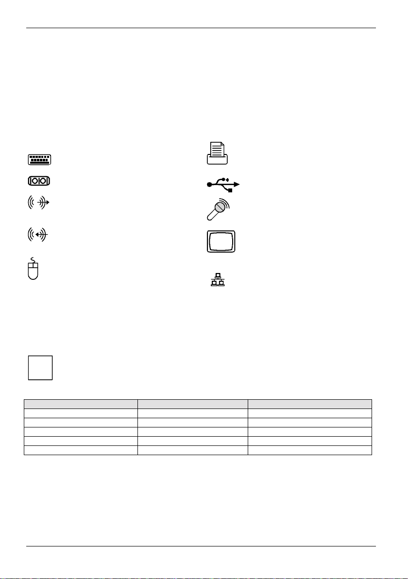
External ports
The positions of the external ports are shown on page "Cover".
PS/2 keyboard port, purple Parallel port/Printer, burgundy
Serial interface, turquoi se USB - Universal Serial B us, black
Audio output (Line out), light green Microphone jack (mono), pink
Audio input (Line in), light blue VGA port, blue (monitor)
PS/2 mouse port, green
Graphics port - Supported screen resolutions
Depending on the operating system used. The screen resolutions in the following table refer to the
mainboard screen controller.
If you are using an external screen c ont roller, you will find details of supported screen resolutions in
the operating manual or technical manual supplied with the controll er.
When using CRT Monitors set the refresh rate to at least 75 Hz f or ergonomic use.
i
When using LCD Monitors set t he ref resh rate to 60 Hz for optimal quali t y.
Screen resolution Maximum refresh rate (Hz) Colour
640 x 480 160 32 bit
800 x 600 85 32 bit
1024 x 768 130 32 bit
1280 x 1024 100 32 bit
1600 x 1200 60 32 bit
LAN
LAN connector
4 - English A26361-D1596-Z121-1-7619
Page 15
Interfaces and connectors
Internal ports and connectors
The positions of the internal port s and connectors are shown on the Cover. Additional information on
some ports is also prov i ded here.
Hard disk connection
An ultra ATA/66 or ultra ATA/100 hard disk must be connec ted with a cable especially designed for
the ultra ATA/66 or ultra ATA/100 mode.
Ê Connect the end of the cable marked with blue to the m ai nboard.
RAM LED
Do not remove memory modules whi l e
RAM LED is on. It mi ght cause short or
!
other unexpected damages due to the
2.5V stand by voltage. Remove memory
modules only when AC Power cord is
disconnected.
A26361-D1596-Z121-1-7619 English - 5
Page 16
Interfaces and connectors
Pin assignment of internal ports
The pin assignment of some i nt ernal connections is shown in Engl i sh in the following.
Some of the following connec tors may be optional!
i
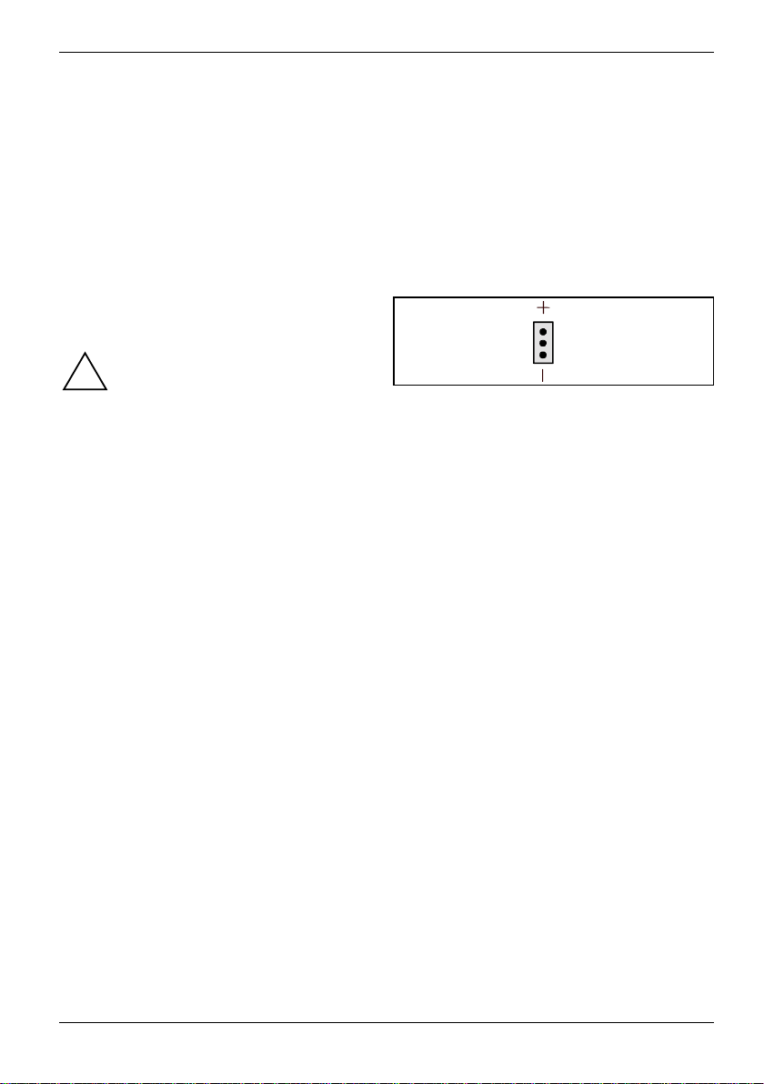
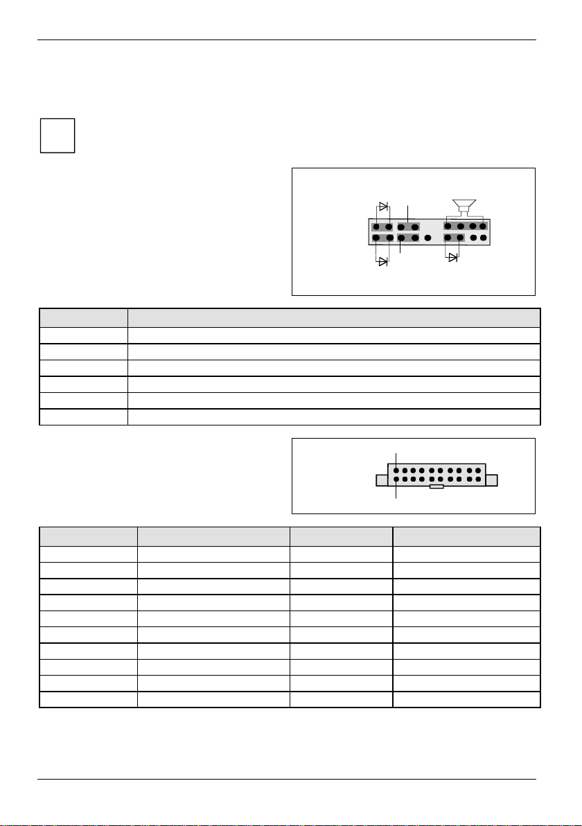
Front panel
Watch the polarity of the LEDs. The positive pole
of the connection cables i s often indicated with a
coloured wire.
Connection Note
Reset
Power On/Off
HD LED
Power On LED Indicates the system state APM or ACPI together with the Sleep LED.
Speaker 0,5 W at 8 Ohm
Sleep LED Indicates the system state APM or ACPI together with the Power-On LED
Power supply ATX
Power On LED
+
+
HD-LED
Power On /Off
Reset
1
+
Sleep LED
11
Pin Signal Pin Signal
1 +3.3 V (P3V3P) 11 +3.3 V (P3V3P)
2 +3.3 V (P3V3P) 12 -12 V (P 12VN)
3GND13GND
4 +5 V (VCC) 14 PS on (low asserted)
5GND15GND
6 +5 V (VCC) 16 GND
7GND17GND
8 Powergood (high asserted) 18 -5 V (P5VN)
9 +5 V Auxiliary (VCC Aux) 19 +5 V (VCC)
10 +12 V (P12VP) 20 +5 V (VCC)
Speaker
6 - English A26361-D1596-Z121-1-7619
Page 17
Interfaces and connectors
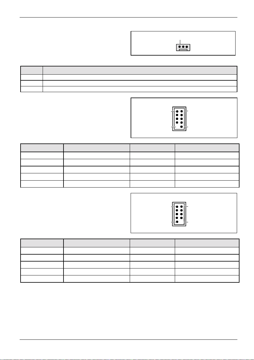
CPU_FAN (CPU Fan Connector)
1
SYS_FAN (System Fan Connector)
(supervised)
Pin Signal
1GND
2 Fan voltage (+12 V)
3 Fan sense
F_USB1 F_USB2 - dual channel
(internal or external via spec i al cable)
Pin Signal Pin Signal
1 VCC C 2 VCC D
3 Data negative C/E 4 Data negative D/F
5 Data positive C/E 6 Data positiv e D/F
7GND8GND
9
Key
10
1 2
9
10
Not Connected
COMB (serial Port)
(via special cable)
1 2
9
10
Pin Signal Pin Signal
1 DCD2 2 RXD2
3 TXD2 4 DTR2
5GND6DSR2
7RTS2 8CTS2
9
A26361-D1596-Z121-1-7619 English - 7
RI
10
NC
Page 18

Interfaces and connectors
F_Audio front panel
if no front panel audio is used pins 5-6 and 9-10
have to be covered with jumpers
Pin Signal Pin Signal
1 Micro input 2 Analog GND
3 Micro bias 4 Analog VCC
5 Right line output 6 Right line return
7NC8Key
9 Left line output 10 Left line return
1 2
CD_IN
Pin Signal
1 Left CD audio input
2 CD GND
3 CD GND
4 Right CD audio input
AUX_IN
1
1
Pin Signal
1 AUX audio input
2AUX GND
3AUX GND
4 Right AUX audio input
8 - English A26361-D1596-Z121-1-7619
Page 19

Settings with jumpers
CPU Speed Setup
Settings with jumpers
Socket A
PCI 1
PCI 2
PCI 3
AGP
BIOS
Battery
DDR 1
DDR 2
CLK_JP
Buzzer
1-2 closed: 100 MHz
2-3 closed: 133 MHz
A26361-D1596-Z121-1-7619 English - 9
Page 20

Add-on modules / Upgrading
Add-on modules / Upgrading
Exit energy-saving mode, switch off the system and remove the power pl ug f rom the
mains outlet, before carrying out any of the procedures described in this chapter!
!
Even when you have switched off the device, parts (e. g. memory modules, AGP and PCI
extension boards) are still supplied with power.
Installing and removing processors
Technical data
AMD Socket A At hl on, AthlonXP or Duron Processor with 100 or 133 MHz front side bus.
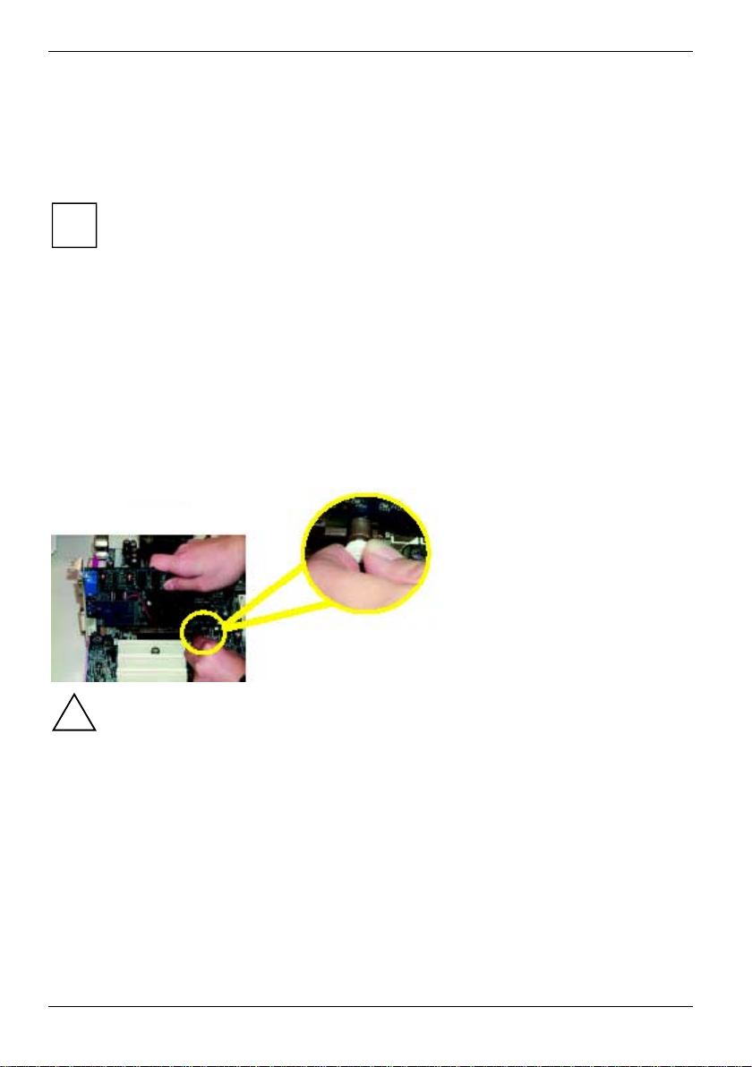
Installing the processor with heat sink and fan
Ê Remove the fan that there may be and the heat sink .
2
2
3
3
4
4
5
5
1
1
A
A
Ê Pull the lever in the direction of the arrow (1) and lift it as far as it will go (2).
Ê Remove the old processor from the sock et (3).
Ê Insert the new processor in the socket so that the angled corner of the proc essor matches the
coding on the socket (A) wi th regard to the position (4).
The angled corner of the processor can al so be at a different location t han shown in the
illustration.
i
Ê Push the lever back down until it clicks into place (5).
10 - English A26361-D1596-Z121-1-7619
Page 21

Add-on modules / Upgrading
Mounting heat sink
Be sure to use heat conducting material between the processor and t he heat sink. If a heat
conducting pad (rubber-like foil) i s already applied to the heat sink , then use it. Otherwise y ou m ust
apply a very thin layer of heat conducting paste.
Heat conducting pads can only be used once. If you remove the heat sink, you must cl ean i t and
apply new heat conducting past e before you remount it.
Ê Depending on the configuration variant,
you must pull a protecti ve foil off the heat
sink or coat the heat si nk with a very thin
layer of heat conducting pas te before
fitting it.
Ê Depending on the processor variant, clips
may also be supplied for mount i ng t he heat
sink that fix it in place.
Never run the processor without the heatsink properly and firml y attached.
Permanent damage will result!
!
A26361-D1596-Z121-1-7619 English - 11
Page 22

Add-on modules / Upgrading
Upgrading main memory
Technical data
Technology: DDR 266 unbuffered DIMM modules
i
Total size: 128 Mbyte up to 2 Gbyte DDR-SDRAM
Granularity: 32, 64, 128, 256, 512 or 1024 Mbyte for one socket
At least one memory modul e m ust be installed. Memory modules with different memory capacities
can be combined.
!
The motherboard has 2 dual inline memory module (DIMM) sockets. The B IOS will automatically
detect memory type and s i ze. To install the memory m odul e, just push it vertically into the DIMM
socket. The DIMM m odul e can only fit in one direction due t o the notch. Memory siz e can vary
between sockets.
184-pin; 2.5 V; 64 Bit, no E CC
DDR 333 unbuffered DIMM modules can be used. However, these memory m odul es are
operated with a memory clock speed of 266 MHz.
You may only use unbuffered 2, 5 V memory modules. Buffered m em ory modules are not
supported.
DDR-DIMM memory modules must meet the PC2100 specif i cation.
12 - English A26361-D1596-Z121-1-7619
Page 23

Add-on modules / Upgrading
Installing a memory module
2
2
Ê Push the holders on each side of the memory s ocket outwards.
Ê Insert the memory module into the soc ket (1).
Ê At the same time flip the lateral holders upwards until the memory module snaps in place (2).
When RAM_LED is ON, do not install or remove Memory Modules f rom socket.
!
Please note that the DIMM m odul e can only fit in one direction due to the notch. Wrong
orientation will cause damage to both memory module and mainboard.
Removing a memory module
1
1
Ê Push the clips on the right and left of t he socket outwards (1).
Ê Pull the memory module from the socket (2).
A26361-D1596-Z121-1-7619 English - 13
Page 24
Add-on modules / Upgrading
Upgrading AGP screen controllers
Technical data:
The AGP slot supports t he m odes 1x/2x/4x with 32bit s and 66MHz. Only 1.5V AGP screen
controllers are supported.
Some older 3.3V AGP screen controllers are coded like 1.5V AGP screen controllers. The
installation of suc h 3.3 V AGP screen controllers can cause serious damage to the
i
mainboard and the AGP screen cont rol l er.
Ê Read the related expansion card’s instruction document before ins talling the expansion card
into the computer.
Ê Remove your computer’s chassis cover, necessary screws and slot bracket from the computer.
Ê Press the expansion card firmly int o the expansion slot.
Ê Be sure the metal contacts on the card are i ndeed seated in the slot.
Ê Replace the screw to secure the slot brac ket of the expansion card.
Ê Replace your computer’s chassis cover.
Ê Power on the computer, if necessary, setup BI OS utility of expansion card from BIOS .
Ê Install related driver from the operating system.
Please carefully pull out the small whitedrawable bar at the end of the AGP slot when you
try to install/ uni nstall the AGP card. Please align the AGP card to the onboard AG P slot
!
and press firmly down on the s l ot . Make sure your AGP card is locked by the small
whitedrawable bar.
14 - English A26361-D1596-Z121-1-7619
Page 25

Add-on modules / Upgrading
Adding PCI cards
Technical data:
32 bit / 33 MHz PCI slot s
5 V and 3.3 V supply voltage
3.3 V auxiliary voltage
PCI bus interrupts - Selecting correct PCI slot
To achieve optimum stability, performanc e and compatibility, avoid the multiple use of I S A
IRQs or PCI IRQ Lines (IRQ shari ng). Should IRQ sharing be unavoidable, then all
i
involved devices and t hei r dri vers must support IRQ sharing.
PCI IRQ Lines connect AGP slots, PCI slots and onboard components to the interrupt controller.
PCI IRQ Lines are permanently wired on the mainboard.
Which ISA IRQs are assi gned to the PCI IRQ Lines is normally automatically spec i fied by the BIOS
(see description in "BI O S Setup").
Monofunctional expansions cards:
Standard AGP and PCI expansion cards require a maximum of one interrupt, which is called the P CI
interrupt INT A. Expansi on cards that do not require an interrupt can be i nstalled in any desired slot.
Multifunctional expansion cards or expansion cards with integrated PCI-PCI bridge:
These expansion cards require up to four PCI interrupts: INT A, INT B , INT C, INT D. How many
and which of these interrupts are used is specified in the doc um entation provided with the card.
The assignment of the PCI i nterrupts to the PCI IRQ Lines is shown in the following table:
PCI INT LINE USB 2.0 LAN AC97 Audio AGP PCI slot
#1 #2 #3
1 (A) - - - A DCB
2 (B) - - B A DC
3 (C) - AA-BA D
4 (D) A ---CBA
Use first PCI slots that have a single PCI I RQ Li ne (no IRQ sharing). If you must use another PCI
slot with IRQ sharing, c heck whether the expansion card properly supports IRQ sharing with the
other devices on this PCI IRQ Line. The drivers of all cards and components on this PCI I RQ Line
must also support IRQ shari ng.
A26361-D1596-Z121-1-7619 English - 15
Page 26

Add-on modules / Upgrading
Replacing lithium battery
In order to permanently save t he system information, a lithium battery is installed to provide the
CMOS-memory with a current. A corresponding error message notifi e s the user when the charge is
too low or the battery is empty. The lithium battery must then be replaced.
Incorrect replacement of the lithium battery may l ead to a risk of explosion!
!
The lithium battery may be repl aced only with an identical battery or with a type
recommended by the manufactu rer.
Do not throw lithium batteries into the household waste. They m ust be disposed of in
accordance with local regulations concerning special waste.
Make sure that you insert the battery the right way round. The plus pole must be on the
top!
The lithium battery holder exi sts in different designs that function in the sam e way.
2
3
2
1
3
3
Ê Press the locking lug in the directi on of the arrow; the battery jumps s om ewhat out of the
holder (1).
Ê Remove the battery (2).
Ê Insert a new lithium battery of the sam e type into the socket (3).
16 - English A26361-D1596-Z121-1-7619
Page 27

BIOS Setup
BIOS Setup
BIOS Setup is an overvi ew of the BIOS Setup Program. The program that allows users to modif y
the basic system configuration. This type of information is stored in battery-backed CMOS RAM so
that it retains the Setup information when the power is turned off.
Entering Setup
Powering ON the computer and pressing <Del> immediately will allow you to enter Setup. If you
require more advanced BIOS settings, please go to "Advanc ed BIOS" setting menu.
Ê To enter Advanced BIOS setting menu, press "Ctrl+F1" key on the BIOS screen.
Control Keys
<↑> Move to previous item
<↓> Move to next item
<←> Move to the item in the left hand
<→> Move to the item in the right hand
<Enter> Select Item
<ESC> Main Menu - Quit and not save changes i nto
<+/PgUp> Increase the numeric value or make changes
<-/PgDn> Decrease the numeric value or make changes
<F1> General help, only for Status P age Setup Menu
<F2> Item Help
<F3> Reserved
<F4> Reserved
<F5> Restore the previous CMOS v al ue f rom CM OS,
<F6> Load the file-safe default CMOS value from
<F7> Load the Optimized Defaults
<F9> Information about BIOS v ersion and CPU
<F10> Save all the CMOS changes, onl y for Main Menu
CMOS Status Page Setup M enu and Option
Page
Setup Menu - Exit current page and return to
Main Menu
and Option Page Setup Menu
only for Option Page Setup Menu
BIOS default table
A26361-D1596-Z121-1-7619 English - 17
Page 28

BIOS Setup
Getting Help
The on-line description of the highli ghted setup function is displayed at the bottom of the s creen.
Status Page Setup Menu / Option Page Setup Menu
Ê Press F1 to pop up a small help window that describes the appropriate keys to use and t he
possible selections for the highlighted item.
Ê To exit the Help Window press <Esc>.
The Main Menu (For example: BIOS Ver. : F1h)
Once you enter AMI BIOS CMOS S et up Utility, the Main Menu (Figure 1) will appear on the screen.
The Main Menu allows you to select from eight setup functions and two exit choices .
Ê Use arrow keys to select among the it em s
Ê press <Enter> to accept or enter the sub-menu.
AMIBIOS SIMPLE SETUP UTILITY - VERSION 1.24b
(C) 1999 American Megatrends, Inc. All Rights Reserv ed
STANDARD CMOS SETUP
BIOS FEATURES SETUP
CHIPSET FEATURES SETUP
POWER MANAGEMENT SETUP
PNP / PCI CONFIGURATION
LOAD BIOS DEFAULTS
LOAD SETUP DEFAULTS
ESC: Quit !"#$ : Select Item F5: Old Values F6: Load BIOS Defaults
F7: Load Setup Defaults F10:Save & Exit
Time, Date , Hard Disk Type
INTEGRATED PERIPHERALS
HARDWARE MONITOR & MISC SETUP
SUPERVISOR PASSWORD
USER PASSWORD
IDE HDD AUTO DETECTION
SAVE & EXIT SETUP
EXIT WITHOUT SAVING
Power Management Setup
This setup page includes all the adjustable items of Green function features.
PNP/PCI Configuration
This setup page includes all t he adj ustable configurations of P CI & PnP ISA resources.
Load Fail-Safe Defaults
Load Fail-Safe Defaults option l oads preset system parameter values to set the system in its most
stable configurations.
18 - English A26361-D1596-Z121-1-7619
Page 29

BIOS Setup
Load Optimized Defaults
Load Optimized Defaults opt i on l oads preset system parameter values to set the system in its
highest performance configurations.
Integrated Peripherals
This setup page includes all onboard peri pheral s.
Hardware Monitor & MISC Setup
This setup page is auto detec t fan and temperature status.
Supervisor Password
Set Change or disable password. It allows you to limit access to the system and/or BIOS s et up.
User Password
Set Change or disable password. It allows you to limit access to the system.
IDE HDD Auto Detection
Automatically c onfigure hard disk parameters.
Save & Exit Setup
Save CMOS value setti ngs to CMOS and exit setup.
Exit Without Saving
Abandon all CMOS value changes and ex i t setup.
A26361-D1596-Z121-1-7619 English - 19
Page 30

BIOS Setup
Standard CMOS Features
AMIBIOS SETUP - STANDARD CMOS SETUP
( C ) 2001 American Megatrends, Inc. All Rights Reserv ed
System Date : Jul 01 2002 Mon
System Time : 16:10:49
TYPE SIZE CYLS HEAD PRECOMP LANDZ SECTOR MODE
Pri Master : Auto
Pri Slave : Auto
Sec Master : Auto
Sec Slave : Auto
Floppy Drive A : 1.44 MB 3
Floppy Drive B : Not Installed
Virus Protection : Disabled
Date is standard format ESC : Exit
Month: Jan - Dec !" : Select Item
Day: 01- 31 PU / PD / + / - : Modify
Year: 1990 - 2099 (Shift) F2 : Color
1/2
Base Memory: 640 Kb
Other Memory: 384 Kb
Extended Memory: 127 Mb
Total Memory: 128 Mb
Date
The date format is <week>, <month>, <day>, <year>.
Week The week, from Sun to Sat, determined by t he BIOS and is display only
Month The month, Jan. through Dec.
Day The day, from 1 to 31 (or the maxi m um al lowed in the month)
Year The year, from 1990 through 2099
Time
The times format in <hour> <minute> <second>. The t i me is calculated base on the 24-hour military
time clock. For exam pl e, 1 p.m. is 13:00:00.
20 - English A26361-D1596-Z121-1-7619
Page 31

BIOS Setup
Primary Master, Slave / Secondary Master, Slave
The category identifies t he types of hard disk from driv e C to F that has been installed in the
computer. There are two types: aut o type, and manual type.
Manual: type is user-defi nabl e;
Auto: will automatically detect HDD t ype.
Note that the specifications of your drive must match with the drive table. The hard disk will not work
properly if you enter improper information for this category.
If you select User Type, related information will be asked to enter to the following items.
Ê Enter the information directly from t he keyboard and press <Enter>.
Such information should be prov i ded i n the documentation form your hard dis k vendor or the system
manufacturer.
Cylinder Num ber of cylinders
Head Number of heads
Precomp Write precomp
Landing Zone Landing zone
Sector Num ber of sectors
Ê If a hard disk has not been installed selec t NONE and press <Enter>.
Floppy Drive A / Drive B
The category identifies the types of floppy disk drive A or drive B that has been i nstalled in the
computer.
Not Installed No floppy dri ve installed
1.2MB, 51/4 5.25 inch AT-type high-densit y drive; 1.2 Mbyte capac i ty
720KB, 31/2 3.5 inch double-sided drive; 720 Kbyte c apacity
1.44MB, 31/2 3.5 inch double-s i ded dri ve; 1.44 Mbyte capacit y
2.88MB, 31/2 3.5 inch double-s i ded dri ve; 2.88 Mbyte capacit y
(3.5 inch when 3 Mode is Enabled).
Virus Protection
If it is set to enable, a warning will flash on the screen when there is any attempt t o writ e to the boot
sector or partition table of the hard disk drive. The system will halt and the following error message
will appear in the mean time. You can run anti-virus program to locate the problem.
Disabled No warning message to appear when anything attempts to ac cess the boot sector or
Enabled Activ at e automatically when the system boots up c ausing a warning message to
A26361-D1596-Z121-1-7619 English - 21
hard disk partition table. (Default Value)
appear when anything attempts t o access the boot sector or hard disk partition table.
Page 32

BIOS Setup
Memory
The category is display-onl y and is determined by POST (Power On S el f Test) of the BIOS.
Base
Memory
Other
Memory
Extended
Memory
The POST of the BIOS will determine the amount of base (or conventional) memory
installed in the system. The value of the base memory is typically 512K for systems
with 512K memory instal l ed on the motherboard, or 640K for systems with 640 K or
more memory installed on the m otherboard.
This refers to the memory l ocated in the 640K to 1024K address space. This is
memory that can be used for different applications. DOS uses this area to load
device drivers to keep as much base memory free for application programs. Most us e
for this area is Shadow RAM.
The BIOS determines how much ex tended memory is present during the POST. This
is the amount of memory l ocated above 1MB in the CPU's m emory address map.
22 - English A26361-D1596-Z121-1-7619
Page 33

BIOS Features Setup
BIOS Setup
( C ) 2001 American Megatrends, Inc. All Rights Reserv ed
BIOS Flash Protection : Auto
1st Boot Device : Floppy
2nd Boot Device : Disabled
3rd Boot Device : Disabled
Floppy Drive Seek : Disabled
BootUp Num-Lock : On
BootUp Num-Lock : On
Password Check : Setup
S.M.A.R.T. for Hard Disk : Disabled
Interrupt Mode : APIC
AMIBIOS SETUP - BIOS FEATURES SETUP
ESC: Quit !"#$: Select Item
F1: Help PU/PD/+/-: Modify
F5: Old Values (Shift)F2: Color
F6: Fail-Safe F7: Optimized
BIOS Flash Protection
This field lets you determine the states that fl ash BIOS.
Auto BIOS enables flash write acc ess automatically when updat i ng BIOS
Enabled BIOS ist protected
data/DMI/ESCD. (Def aul t Value)
1st / 2nd / 3rd Boot Device
Disabled Disabled thi s function
Floppy: 1.44MB
31/2 .
BBS-0(Network):
Realtek Boot
Agent
IDE-0: ST320420A Select your boot devic e pri ori ty by IDE Device.
USB RMD-FDD: Apacer Handy Drive Select your boot device priority by USB Device.
Boot order depends on the devices you use, for example: Floppy , HDD, CD-ROM...
Select your boot device pri ori ty by Floppy
Select your boot devic e pri ori ty by Network.
A26361-D1596-Z121-1-7619 English - 23
Page 34

BIOS Setup
Floppy Drive Seek
During POST, BIOS will determine the floppy dis k drive installed is 80 tracks. 720K, 1.2M and
1.44M are all 80 tracks.
Enabled BIOS searches for floppy disk drive to determine i t i s 80 tracks. Note that BIOS
Disabled BIOS will not search for the type of floppy dis k drive by track number. Note that
can not tell from 720K, 1. 2M or 1.44M drive type as they are all 80 tracks.
there will not be any warning message if the drive installed is 360K. (Default
value)
BootUp Num-Lock
Off When bootup, setting keypad is arrow keys
On When bootup, setting keypad is number keys. (Default value)
Password Check
Please refer to the detail on P assword Check.
Setup The user must enter correct password in order to access BIOS setup utility
Always The user must enter correct password in order to access the system and/or BIOS
(Default Value)
Setup.
S.M.A.R.T. for Hard Disks
Enabled Enable HDD S.M.A.R.T. Capability (Default value).
Disabled Disable HDD S.M.A.R.T. Capability.
APIC Interrupt Mode
APIC Through IOAP I C generate more IRQ for system use. (Default Value)
PIC Use AT standard IRQ cont rol l ers to generate IRQ.
When you already have IOAPIC enabl e system and want to upgrade the system please note, since
running an IOAPIC enabled OS (like Windows NT, Windows 2000, Windows XP...) system with
none IOAPIC HW support will cause t he system to hang. Followi ng are some situations users m i ght
run into: 1.An IOAPIC enabled OS and change the BIOS setting from IOAP I C to PIC, this will cause
your system to hang.
24 - English A26361-D1596-Z121-1-7619
Page 35

Chipset Features Setup
We would not suggest you change the chipset default setti ng unl ess you really need it.
AMIBIOS SETUP - CHIPSET FEATURES SETUP
( C ) 2001 American Megatrends, Inc. All Rights Reserved
Configure SDRAM by SPD : Enabled
SDRAM Frequency : Auto
SDRAM CAS# Latency : 2.5
SDRAM Command Rate : 2T Command
AGP Mode : 4X
AGP Comp. Driving : Auto
Manual AGP Comp. Driving : DA
AGP Fast Write : Disabled
AGP Aperture Size : 64MB
AGP Read Synchronization : Disabled
PCI Delay Transaction : Disabled
USB Controller : 6 USB Ports
USB 1.1 Legacy Support : Disabled
USB 1.1 64/60 Emulation : Disabled
Configure SDRAM by SPD
ESC: Quit !"#$: Select Item
F1: Help PU/PD/+/- : Modify
F5: Old Values (Shift)F2: Color
F6: Fail-Safe F7 : Optimized
BIOS Setup
Disabled Disable Configure SDRAM by SPD.
Enabled Enable Configure SDRAM by SPD. (Default Value)
SDRAM Frequency
200MHz Set SDRAM Frequency to 200MHz.
266MHz Set SDRAM Frequency to 266MHz.
Auto Set SDRAM Frequency to Auto. (Default Value)
A26361-D1596-Z121-1-7619 English - 25
Page 36

BIOS Setup
SDRAM CAS# Latency
This item will be available when "Configure SDRAM by SPD" set to Disabled.
2.5 For Slower SDRAM DIMM module. (Default Value)
2 For Fastest SDRAM DIM M module.
SDRAM Command Rate
2T Command Set SDRAM Command Rat e to 2T Command. (Default Value)
1T Command Set SDRAM Command Rat e to 1T Command.
AGPMode
4X Set A G P M ode to 4X. (Default Value)
2X Set A GP Mode to 2X.
1X Set A GP Mode to 1X.
AGP Comp. Driving
Manual Set AGP Comp. Driving t o M anual .
Auto Set AGP Comp. Driving to Auto. (Default Value)
If AGP Comp. Driving i s Manual.
Manual AGP Comp. Driving : 00~FF
Manual AGP Comp. Driving
If "AGP Comp. Driving" set to "Manual", this it em can be set : 00 ~ FF
AGP Fast Write
Disabled Disable AGP Fast Write. (Default V al ue)
Enabled Enable AGP Fast Write.
AGP Aperture Size
256MB Set AGP Aperture Size to 256 MB
128MB Set AGP Aperture Size to 128 MB
64MB Set AGP A perture Size to 64 MB
32MB Set AGP A perture Size to 32 MB
16MB Set AGP A perture Size to 16 MB
8MB Set AGP Aperture Size to 8 MB
4MB Set AGP Aperture Size to 4 MB
26 - English A26361-D1596-Z121-1-7619
Page 37

AGP Read Synchronization
Disabled Disable AGP Read Synchronization. (Default Value)
Enabled Enable AGP Read Synchronization.
PCI Delay Transaction
Disabled Disable PCI Delay Transaction.(Def aul t Value)
Enabled Enable PCI Delay Transaction.
USB Controller
Disabled Disable USB Controller function.
2 USB ports E nabl e 2 US B ports.
4 USB ports E nabl e 4 US B ports.
6 USB ports E nabl e 6 US B ports. (Default Value)
USB 1.1 Legacy Support
Disabled Disable USB 1.1 Legacy Support Functi on. (Default Value)
No Mice Set USB 1.1 Legacy Support wi thout mouse.
All Device Set USB 1.1 Legacy Support with all devices.
BIOS Setup
USB 1.1 64/60 Emulation
Disabled Disable this Function. (Default Value)
Enabled To use USB mouse under Win NT environment, set USB Legacy Support t o
KB/Mouse/FDD and USB Port 64/60 Emulation to enabled.
HLT Command Detect
Disabled If you experience instabilities or problems with sound or v ideo files, try disabling
Enabled Allows the CPU to disconnect from the system bus when the operating system
A26361-D1596-Z121-1-7619 English - 27
this function. Cert ai n add-on cards or drivers may require this feature to be
turned off due to extremely high PCI bus utilization or non-standard PCI bus
usage.
issues an HLT command. This results in a considerable decreas e i n power
consumption in the idle s tate with modern operating systems. Use this setting for
most cool and silent system behavior (default value).
Page 38

BIOS Setup
Power Management Setup
( C ) 2001 American Megatrends, Inc. All Rights Reserv ed
AMIBIOS SETUP - POWER MANAGEMENT SETUP
ACPI Standby State : S1/POS
Power LED in S1 State : Blinking
USB Dev. Wakeup From S3 : Disabled
Suspend Time Out (Min.) : Disabled
IRQ 3 : Monitor
IRQ 4 : Monitor
IRQ 5 : Ignore
IRQ 7 : Monitor
IRQ 9 : Ignore
IRQ 10 : Ignore
IRQ 11 : Ignore
IRQ 13 : Ignore
IRQ 14 : Monitor
IRQ 15 : Ignore
Soft-Off by Power Button : Instant off
AC Back Function : Soft-Off
Modem Ring/Wake On Lan : Enabled
PME Event Wake Up : Enabled
Keyboard Wakeup From : S1(Suspend)
PS/2 Mouse Wakeup From : S1(Suspend
ACPI Standby State
Resume On RTC Alarm : Disabled
RTC Alarm Date : 15
RTC Alarm Hour : 12
RTC Alarm Minute : 30
RTC Alarm Second : 30
ESC: Quit !"#$: Select Item
F1: Help PU/PD/+/- : Modify
F5: Old Values (Shift)F2: Color
F6: Fail-Safe F7 : Optimized
S1/POS Set ACPI standby state to S1.
S3/STR Set ACPI standby state to S3 (Default Value).
28 - English A26361-D1596-Z121-1-7619
Page 39

Power LED in S1 state
Blinking In standby mode, power LED will blink.
Dual/OFF In standby mode (Default Value):
a. If use single color LED, power LED will turn off.
b. If use dual color LED, power LED will t urn t o another color.
USB Dev. Wakeup From S3
Disabled Disable USB Dev Wakeup From S3. (Default Value)
Enabled Enable USB Dev Wakeup From S3.
Suspend Time Out (Min.)
Disabled Disable Suspend Time Out Function. (Default Value)
1 Enable Suspend Time Out after 1min.
2 Enable Suspend Time Out after 2mins.
4 Enable Suspend Time Out after 4mins.
8 Enable Suspend Time Out after 8mins.
10 Enable Suspend Time Out after 10mins.
20 Enable Suspend Time Out after 20mins.
30 Enable Suspend Time Out after 30mins.
40 Enable Suspend Time Out after 40mins.
50 Enable Suspend Time Out after 50mins.
60 Enable Suspend Time Out after 60mins.
BIOS Setup
IRQ 3~IRQ15
Ignore Ignore IRQ3 ~IRQ15.
Monitor M oni tor IRQ3~IRQ15.
Soft-Off Power Button
Instant off The user press the power button once, he can turn off the system (Default Value)
Suspend The user press the power button once, then he can enter suspend m ode.
AC Back Function
Soft-Off Always in Off state when AC back. (Default value)
Full-On Always power on the system when AC back.
Memory Sys tem power on depends on the status before A C lost.
A26361-D1596-Z121-1-7619 English - 29
Page 40

BIOS Setup
Modem Ring/Wake On LAN
Disabled Disable Modem Ring On / Wake On LAN function.
Enabled The Modem Ring / LAN wake up will bring the system out of soft-off or suspend
state if this opti on i s set "Enabled". (Default V al ue)
PME Event Wake Up
Disabled Disable PME Event Wake Up.
Enabled Enabled PME Event Wake Up. (Default Value)
Keyboard Wakeup From
S1(Suspend) Key board i s able to Wakeup the system from S1(Suspend) state (Default value)
S1/S3 Keyboard is able to Wakeup the system from S1/S3 state.
S1/S3/S4/S5 Keyboard is able to Wakeup the system from S1/S3/S4/S5 state.
PS/2 Mouse Wakeup From
S1(Suspend) PS /2 Mouse is able to Wakeup the system from S1(Suspend) state (Default
S1/S3 PS/2 Mouse is able to Wakeup the system from S1/S3 state.
S1/S3/S4/S5 PS/2 Mouse is able to Wak eup the system from S1/S3/S4/S5 state.
value)
Resume On RTC Alarm
Disabled Disable this function. (Defaul t Value)
Enabled Enable alarm function to POWER ON system
You can set "Resume On RTC Alarm " i tem to enabled and key in Data/ti m e to power on system.
If RTC Alarm Lead To Power On is Enabled.
− RTC Alarm Date : Everyday, 1~31
− RTC Alarm Hour : 0~23
− RTC Alarm Minute : 0~59
− RTC Alarm Second : 0~59
30 - English A26361-D1596-Z121-1-7619
Page 41

PNP/PCI Configuration
BIOS Setup
( C ) 2001 American Megatrends, Inc. All Rights Reserv ed
OnChip VGA Frame Buffer : 32MB
VGA Boot From : AGP
PCI Slot 1 IRQ Priority : Auto
PCI Slot 2 IRQ Priority : Auto
PCI Slot 3 IRQ Priority : Auto
Realtek LAN ROM initial : Yes
AMIBIOS SETUP - PNP/PCI CONFIGURATION
ESC: Quit !"#$: Select Item
F1: Help PU/PD/+/- : Modify
F5: Old Values (Shift)F2: Color
F6: Fail-Safe F7: Optimized
OnChip VGA Frame Buffer
None Disable this functi on
8MB Set OnChi p VGA Frame Buffer to 8MB.
16MB Set OnChip VGA Frame Buffer to 16MB.
32MB Set OnChip VGA Frame Buffer to 32MB. (Default Value)
VGA Boot From
PCI Set VGA Boot from PCI VGA Card.
AGP Set VGA Boot from AGP VGA Card. (Default Value)
A26361-D1596-Z121-1-7619 English - 31
Page 42

BIOS Setup
PCI Slot 1, 2, 3 IRQ Priority
Auto The system will reserved a free IRQ for PCI slot 1, 2, 3 device. (Default Value)
3 The system will reserved IRQ3 for PCI slot 1, 2, 3 device if no legacy
ISA device using IRQ3.
4 The system will reserved IRQ4 for PCI slot 1, 2, 3 device if no legacy
ISA device using IRQ4.
5 The system will reserved IRQ5 for PCI slot 1, 2, 3 device if no legacy
ISA device using IRQ5.
7 The system will reserved IRQ7 for PCI slot 1, 2, 3 device if no legacy
ISA device using IRQ7.
10 The system will reserved IRQ10 for PCI slot 1, 2, 3 device if no legacy
ISA device using IRQ10.
11 The system will reserved IRQ11 for PCI slot 1, 2, 3 device if no legacy
ISA device using IRQ11.
Realtek LAN ROM initial
No Disable Realtek LAN ROM i ni tialization
Yes Enable Realtek LAN ROM initialitati on (Default Value)
32 - English A26361-D1596-Z121-1-7619
Page 43

BIOS Setup
Load Fail-Safe Defaults
Fail-Safe defaults cont ai n t he m ost appropriate system parameter values of to configure the system
to achieve maximum stability.
AMIBIOS SIMPLE SETUP UTILITY - VERSION 2.00
( C ) 2001 American Megatrends, Inc. All Rights Reserved
STANDARD CMOS SETUP
BIOS FEATURES SETUP
CHIPSET FEATURES SETUP
POWER MANAGEMENT SETUP
PNP / PCI CONFIGURATION
LOAD FAIL-SAFE DEFAULTS
LOAD OPTIMIZED DEFAULTS
ESC: Quit !"#$: Select Item F5: Old Values F6: Fail-Safe Values
F7: Optimized Values F10:Save & Exit
Load Fail-Safe Defaults (Y/N)? N
Load Fail-Safe Defaults
INTEGRATED PERIPHERALS
HARDWARE MONITOR & MISC SETUP
SUPERVISOR PASSWORD
USER PASSWORD
IDE HDD AUTO DETECTION
SAVE & EXIT SETUP
EXIT WITHOUT SAVING
A26361-D1596-Z121-1-7619 English - 33
Page 44

BIOS Setup
Load Optimized Defaults
Optimized defaults c ontain the most appropriate system parameter values to configure the system
to achieve maximum perf orm ance.
AMIBIOS SIMPLE SETUP UTILITY - VERSION 2.00
( C ) 2001 American Megatrends, Inc. All Rights Reserved
STANDARD CMOS SETUP
BIOS FEATURES SETUP
CHIPSET FEATURES SETUP
POWER MANAGEMENT SETUP
PNP / PCI CONFIGURATION
LOAD FAIL-SAFE DEFAULTS
LOAD OPTIMIZED DEFAULTS
ESC: Quit !"#$: Select Item F5: Old Values F6: Fail-Safe Values
F7: Optimized Values F10:Save & Exit
Load Optimized Defaults (Y / N)? N
Load Optimized Defaults
INTEGRATED PERIPHERALS
HARDWARE MONITOR & MISC SETUP
SUPERVISOR PASSWORD
USER PASSWORD
IDE HDD AUTO DETECTION
SAVE & EXIT SETUP
EXIT WITHOUT SAVING
34 - English A26361-D1596-Z121-1-7619
Page 45

Integrated Peripherals
AMIBIOS SETUP - Integrated Peripherals
( C ) 2001 American Megatrends, Inc. All Rights Reserved
OnBoard IDE : Both
IDE1 Conductor Cable : Auto
IDE2 Conductor Cable : Auto
OnBoard FDC : Auto
OnBoard Serial Port 1 : Auto
OnBoard Serial Port 2 : Auto
Serial Port2 Mode : Normal
OnBoard Parallel Port : Auto
Parallel Port Mode : ECP
Parallel Port IRQ : Auto
Parallel Port DMA : Auto
OnBoard AC’97 Audio : Auto
Onboard Lan Chip : Enabled
BIOS Setup
ESC: Quit !"#$: Select Item
F1: Help PU/PD/+/- : Modify
F5: Old Values (Shift)F2: Color
F6: Fail-Safe F7: Optimized
OnBoard IDE
Disabled Disable OnBoard IDE.
Primary Only Primary IDE channel is enabled.
Secondary Only Secondary IDE channel i s enabled.
Both Both Primary & Secondary IDE channel will be enabled. (Default V alue)
A26361-D1596-Z121-1-7619 English - 35
Page 46

BIOS Setup
IDE1 Conductor Cable
Auto Will be automatically detected by BIOS. (Default Value)
ATA66/100/133 Set I DE 1 Conductor Cable to ATA66/100/133 (Please make sure your IDE
ATA33 Set IDE1 Conductor Cable to ATA33 (P l ease make sure your IDE device and
device and cable is compatible with ATA66/100/133
cable is compatible with ATA33)
IDE2 Conductor Cable
Auto Will be automatically detected by BIOS. (Default Value)
ATA66/100/133 Set I DE 1 Conductor Cable to ATA66/100 (Pleas e m ake sure your IDE device
ATA33 Set IDE1 Conductor Cable to ATA33 (P l ease make sure your IDE device and
and cable is compatible with ATA66/100
cable is compatible with ATA33)
On Board FDC
Auto Set On Board Floppy Disk Controller t o A uto. (Default Value)
Disabled Disable On Board Floppy Disk Controller.
Enabled Enable On Board Floppy Disk Controll er.
Onboard Serial Port 1
Auto BIOS will automatically setup the port 1 address . (Default Value)
Disabled Disable onboard Serial port 1.
3F8/COM1 Enable onboard Serial port 1 and address is 3F8
2F8/COM2 Enable onboard Serial port 1 and address is 2F8
3E8/COM3 Enable onboard Seri al port 1 and address is 3F8
2E8/COM4 Enable onboard Seri al port 1 and address is 2F8
Onboard Serial Port 2
Auto BIOS will automatically setup the port 2 address . (Default Value)
Disabled Disable onboard Serial port 2.
3F8/COM1 Enable onboard Serial port 2 and address is 3F8
2F8/COM2 Enable onboard Serial port 2 and address is 2F8
3E8/COM3 Enable onboard Seri al port 2 and address is 3F8
2E8/COM4 Enable onboard Seri al port 2 and address is 2F8
36 - English A26361-D1596-Z121-1-7619
Page 47

BIOS Setup
Serial Port 2 Mode
Normal Normal operati on. (Default Value)
IrDA Onboard I/O chip supports I rDA.
ASKIR Onboard I/O chip supports ASKIR.
OnBoard Parallel port
Auto Set On Board LPT port is Auto. (Default Value)
Disabled Disable On Board LPT port.
378 Enable On Board LPT port and address is 378.
278 Enable On Board LPT port and address is 278.
3BC Enable On Board LP T port and address is 3BC.
Parallel Port Mode
Normal Normal Operati on.
EPP Using Parallel port as Enhanced Parallel Port.
ECP Using P arallel port as Extended Capabilities Port. (Default V alue)
EPP+ECP Using Parallel port as Enhanced Parallel Port & Extended Capabilities Port.
Parallel Port IRQ
Auto Set Auto to parallel Port IRQ DMA Channel. (Default Value)
5 Set Parallel Port IRQ to 5.
7 Set Parallel Port IRQ to 7.
Parallel Port DMA
Auto S et Auto to parallel port mode DMA Channel. (Default Value)
0 Set Parallel Port DMA to 0.
1 Set Parallel Port DMA to 1.
3 Set Parallel Port DMA to 3.
OnBoard AC'97 Audio
Auto Enabl e onboard AC'97 audio function. (Default Value)
Disabled Disable this function.
Onboard Lan Chip
Enabled Enable Onboard Lan Chip function. (Default Value)
Disabled Disable this function.
A26361-D1596-Z121-1-7619 English - 37
Page 48

BIOS Setup
Hardware Monitor & MISC Setup
AMIBIOS SETUP - HARDWARE MONITOR & MISC SETUP
( C ) 2001 American Megatrends, Inc. All Rights Reserved
Reset Case Open Status : No
Case Status : Open
CPU Host Clock (Mhz) : 100
CPU Temp.: 35°C / 95°F
System Temp. : 33°C / 91°F
CPU Fan Speed : 7031 RPM
System Fan Speed : 0 RPM
Vcore : +1.760V
Vtt : +1.264V
+3.300V : +3.280V
+5.000V : +4.999V
+12.000V : +12.352V
5VSB : +4.999V
ESC: Quit !"#$: Select Item
F1: Help PU/PD/+/- : Modify
F5: Old Values (Shift)F2: Color
F6: Fail-Safe F7: Optimized
Reset Case Open Status Case Status
If the case is closed, "Case Status" will show "Closed".
If the case has been opened, "Case St atus" will show "Open".
If you want to reset "Cas e Status" value, set " Reset Case Open Status" to "Yes" and save CMOS,
your computer will restart.
CPU / System Temp.
Detect CPU / System Temperature automatically .
CPU / System Fan Speed
Detect CPU / System Fan speed status automat i cally.
Current Voltage (V) Vcore / Vtt / +3.3V / +5V / +12V / 5VSB
Detect system's voltage status automatically.
38 - English A26361-D1596-Z121-1-7619
Page 49

BIOS Setup
Set Supervisor / User Password
When you select this funct i on, the following message will appear at the center of the screen to
assist you in creat i ng a password.
AMIBIOS SIMPLE SETUP UTILITY - VERSION 2.00
( C ) 2001 American Megatrends, Inc. All Rights Reserved
STANDARD CMOS SETUP
BIOS FEATURES SETUP
CHIPSET FEATURES SETUP
POWER MANAGEMENT SETUP
PNP / PCI CONFIGURATION
LOAD FAIL-SAFE DEFAULTS
LOAD OPTIMIZED DEFAULTS
ESC: Quit !"#$: Select Item F5: Old Values F6: Fail-Safe Values
F7: Optimized Values F10:Save & Exit
Enter new supervisor pass word:
Change / Set / Disable Password
Ê Type the password, up to six characters, and press <Enter>.
You will be asked to confirm the password.
Ê Type the password again and press <Enter>. You may also press <Esc> to abort the s el ection
and not enter a password.
Ê To disable password, just press <Enter> when you are prompted to enter password. A
message
"PASSWORD DISABLED" will appear to confirm the password being disabled.
Once the password is disabled, the system will boot and you can enter Setup freely.
The BIOS Setup program allows you to specify two separate passwords: a SUPERVISOR PASS
WORD and a USER PASSWORD. When disabled, anyone may access all BIOS Setup program
function. When enabled, the Supervisor password is required for enteri ng the BIOS Setup program
and having full configuration fields, the User password is required to access only bas i c items.
If you select "Always" at "Password Check" in BIOS Features S etup Menu, you will be prompted for
the password every time the system is rebooted or any time you try to ent er Setup Menu
If you select "Setup" at "Password Check" in BIOS Features Setup Menu, you will be prompted only
when you try to enter Setup.
INTEGRATED PERIPHERALS
HARDWARE MONITOR & MISC SETUP
SUPERVISOR PASSWORD
USER PASSWORD
IDE HDD AUTO DETECTION
SAVE & EXIT SETUP
EXIT WITHOUT SAVING
.
A26361-D1596-Z121-1-7619 English - 39
Page 50

BIOS Setup
IDE HDD Auto Detection
AMIBIOS SETUP - STANDARD CMOS SETUP
( C ) 2001 American Megatrends, Inc. All Rights Reserved
System Date : Jul 01 2002 Mon
System Time : 16:10:49
TYPE SIZE CYLS HEAD PRECOMP LANDZ SECTOR MODE
Pri Master : Auto
Pri Slave : Auto
Sec Master : Auto
Sec Slave : Auto
Floppy Drive A : 1.44 MB 31/2
Floppy Drive B : Not Installed
Virus Protection : Disabled
Date is standard format ESC : Exit
Month: Jan - Dec !" : Select Item
Day: 01- 31 PU / PD / + / -: Modify
Year: 1990 - 2099 (Shift) F2 : Color
Base Memory : 640 Kb
Other Memory : 384 Kb
Extended Memory : 127 Mb
Total Memory : 128 Mb
Type "Y" will accept the H.D.D. paramet er reported by BIOS.
Type "N" will keep the old H.D.D. parameter setup. If the hard disk cylinder number is ov er 1024,
then the user can select LBA mode or LARGER mode for DOS partition l a rger t han 528 M B.
40 - English A26361-D1596-Z121-1-7619
Page 51

Save & Exit Setup
AMIBIOS SIMPLE SETUP UTILITY - VERSION 2.00
( C ) 2001 American Megatrends, Inc. All Rights Reserved
STANDARD CMOS SETUP
BIOS FEATURES SETUP
CHIPSET FEATURES SETUP
POWER MANAGEMENT SETUP
PNP / PCI CONFIGURATION
LOAD FAIL-SAFE DEFAULTS
LOAD OPTIMIZED DEFAULTS
ESC: Quit !"#$: Select Item F5: Old Values F6: Fail-Safe Values
F7: Optimized Values F10:Save & Exit
Type "Y" will quit the Setup Utility and sav e t he user setup value to RTC CMOS.
Type "N" will return to Setup Utility.
Save to CMOS and EXIT (Y/N)? Y
Save Data to CMOS & Exit SETUP
INTEGRATED PERIPHERALS
HARDWARE MONITOR & MISC SETUP
SUPERVISOR PASSWORD
USER PASSWORD
IDE HDD AUTO DETECTION
SAVE & EXIT SETUP
EXIT WITHOUT SAVING
BIOS Setup
A26361-D1596-Z121-1-7619 English - 41
Page 52

BIOS Setup
Exit Without Saving
AMIBIOS SIMPLE SETUP UTILITY - VERSION 2.00
( C ) 2001 American Megatrends, Inc. All Rights Reserved
STANDARD CMOS SETUP
BIOS FEATURES SETUP
CHIPSET FEATURES SETUP
POWER MANAGEMENT SETUP
PNP / PCI CONFIGURATION
LOAD FAIL-SAFE DEFAULTS
LOAD OPTIMIZED DEFAULTS
ESC: Quit !"#$: Select Item F5: Old Values F6: Fail-Safe Values
F7: Optimized Values F10:Save & Exit
Type "Y" will quit the Setup Utility without saving to RTC CMOS.
Type "N" will return to Setup Utility.
Quit without saving (Y/N)? N
Abandon all Data & Exit SETUP
INTEGRATED PERIPHERALS
HARDWARE MONITOR & MISC SETUP
SUPERVISOR PASSWORD
USER PASSWORD
IDE HDD AUTO DETECTION
SAVE & EXIT SETUP
EXIT WITHOUT SAVING
42 - English A26361-D1596-Z121-1-7619
Page 53

BIOS Setup
BIOS update
When should a BIOS update be carried out?
Fujitsu Siemens Computers makes new BIOS versions available to ensure compatibility to new
operating systems, new software or new hardware. In addition, new BIOS functions can also be
integrated.
A BIOS update should always also be carried out when a problem exis t s that cannot be solved wit h
new drivers or new software.
Where can I obtain BIOS updates?
The BIOS updates are available on the Internet at www.fujitsu-siemens.com
How does a BIOS update work?
1. BIOS update under DOS with bootable BIOS update floppy disk - brief descri p ti on
Ê Download the update file from out website to your PC.
Ê Insert an empty floppy disk (1.44 M B ).
Ê Run the update file (e.g. 1522103.EXE).
Ê A bootable update floppy disk is created. Leave this floppy disk i n the drive.
Ê Restart the PC.
Ê Follow the instructions on screen.
A26361-D1596-Z121-1-7619 English - 43
Page 54

Glossary
Glossary
The technical terms and abbrevi ations given below represent only a s el ection of the full list of
common technical term s and abbreviations.
Not all technical terms and abbreviations listed here are valid for the described mainboard.
ACPI Advanced Configurati on and
Power Management Interface
AMR Audio Modem Riser MCH Memory Controller Hub
AOL Alert On LAN MMX MultiMedia eXtensi on
APM Adv anced Power Management P64H PCI64 Hub
ATA Advanced Technology
Attachment
BIOS Basic Input Output Sys tem PXE Preboot eXecution Environment
BMC Baseboard management
controller
CAN Controller Area Network RAMDAC Random A ccess Memory Digit al
CPU Central Processing Unit RDRAM Rambus Dynamic Random
CNR Comm uni cation Network Riser RIMM Rambus Inline Memory Module
C-RIMM Continuity Rambus Inline
Memory Module
DIMM Dual Inline Memory Module SB Soundblaster
ECC Error Correcting Code SDRAM Synchronous Dynamic Random
EEPROM Electrical Erasable
Programmable Read Only
Memory
FDC Floppy disk c ont rol l er SI M D Streaming Mode Inst ruction
FIFO First-In First-Out SMBus System Management Bus
FSB Front Side Bus SVGA Super Video Graphic Adapter
FWH Fi rm ware Hub USB Universal Serial Bus
GMCH Graphics and Memory Controller
Hub
GPA Graphics Performance
Accelerator
I2C Inter Integrat ed Ci rcuit
IAPC Instantly Available Power
Managed Desktop PC Design
ICH I/O Controller Hub
IDE Int el l igent Drive Electronics
IPSEC Internet Protocol Security
ISA Industrial Standard Architecture
PCI Peri pheral Com ponent
Interconnect
RAM Random Access M em ory
Analogue Converter
Access Memory
RTC Real Time Clock
Access Memory
SGRAM Synchronous Graphic Random
Access Memory
(Single Instruction Multiple Data)
VGA Video Graphic Adapter
WOL Wak e On LA N
44 - English A26361-D1596-Z121-1-7619
 Loading...