

Fujitsu siemens D1085 Technical Manual
Introduction
This Technical Manual applies for the system board D1085.
This system board is available in different configuration levels. Depending on the
hardware configuration of your device, it may be that you cannot find several options in
i
your version of the system board, even though they are described.
You may find further information in the description "BIOS Setup".
Further information to drivers is provided in the readme files on hard disk or on the supplied drivers
diskettes or on the "Drivers & Utility" or "ServerStart" CD.
Notational conventions
The meanings of the symbols and fonts used in this manual are as follows:
Pay particular attention to texts marked with this symbol. Failure to observe this warning
endangers your life, destroys the system, or may lead to loss of data.
!
This symbol is followed by supplementary information, remarks and tips.
i
Texts which follow this symbol describe activities that must be performed in the order shown.
This symbol means that you must enter a blank space at this point.
This symbol means that you must press the Enter key.
Texts in this typeface
Texts in this bold typeface
Texts in italics
"Quotation marks" indicate names of chapters and terms that are being emphasized.
indicate commands or menu items.
are screen outputs.
are the entries you make via the keyboard.
A26361-D1085-Z120-4-7419
English - 1
Important notes
Important notes
Store this manual close to the device. If you pass on the device to third parties, you should also
pass on this manual.
Be sure to read this page carefully and note the information before you open the PC.
!
You cannot access the components of the system board without first opening the device.
How to dismantle and reassemble the device is described in the Operating Manual
accompanying the device.
Please note the information provided in the chapter "Safety" in the Operating Manual of
the PC.
Incorrect replacement of the lithium battery may lead to a risk of explosion. It is therefore
essential to observe the instructions in the chapter "Add-on modules
lithium battery“.
The lithium battery must be replaced with an identical battery or a battery type
recommended by the manufacturer (CR2032).
Do not throw lithium batteries into the trashcan. It must be disposed of in accordance with
local regulations concerning special waste.
The shipped version of this board complies with the requirements of the EEC
directive 89/336/EEC "Electromagnetic compatibility".
Compliance was tested in a typical PC configuration.
When installing the board, refer to the specific installation information in the
Operating Manual or Technical Manual of the receiving device.
“ - "Replacing the
Connecting cables for peripherals must be adequately insulated to avoid interference.
Components can become very hot during operation. Make sure you do not touch
components when making extensions to the system board. There is a danger of burns!
!
The warranty expires if the device is damaged during the installation or replacement of
system expansions. Information on which system expansions you can use is available
i
from your sales office or the customer service.
2 - English
A26361-D1085-Z120-4-7419

Important notes
Boards with electrostatic sensitive devices (ESD) may be identified by labels.
When you handle boards fitted with ESDs, you must observe the following points under all
circumstances:
• You must always discharge yourself (e.g. by touching a grounded object) before working.
• The equipment and tools you use must be free of static charges.
• Pull out the power plug before inserting or pulling out boards containing ESDs.
• Always hold boards with ESDs by their edges.
• Never touch pins or conductors on boards fitted with ESDs.
A26361-D1085-Z120-4-7419
English - 3

Features
Features
The components and connectors marked do not have to be present on the system board.
•
System board in ATX format
•
Intel Pentium II processor with 66 MHz Front Side Bus for slot 1 processor socket
or
•
Intel Celeron processor with 66 MHz Front Side Bus for slot 1 processor socket
Intel Pentium II and Celeron processors support MMX technology. The size of first-level cache and
second-level cache is depending on the processor used.
•
Processor cache module with SEC contact technology for Intel slot 1 processor slot (SEC =
Single Edge Contact)
•
16 to 256 Mbytes main memory (SDRAM)
•
256 to 768 Mbytes main memory (SDRAM)
•
Error identification and error recognition via ECC
•
Flash BIOS
•
AGP slot for AGP graphics controller (AGP = Accelerated Graphics Port)
•
4 PCI slots (all with busmaster capability)
•
3 ISA slots
•
IDE hard disk controller connected to PCI bus for up to four IDE drives
(e.g. IDE hard disk drives, ATAPI CD ROM drive), (ultra DMA33 mode capable)
•
Real-time clock/calendar with integrated battery backup
•
Floppy disk controller (up to 2.88 Mbytes format)
•
Supports booting from a 120 Mbyte IDE floppy disk drive
•
Parallel port (ECP- and EPP-compatible)
•
2 serial ports (16C550 compatible with FIFO)
•
PS/2 mouse port
•
PS/2 keyboard port
•
Security functions
•
USB (Universal Serial Bus)
•
Energy saving functions
•
Connector for chipcard reader
•
Fan connector
•
Connector for infrared connection
•
Wakeup on LAN (WOL)
•
Prepared for system monitoring
•
Cover detection
4 - English
A26361-D1085-Z120-4-7419
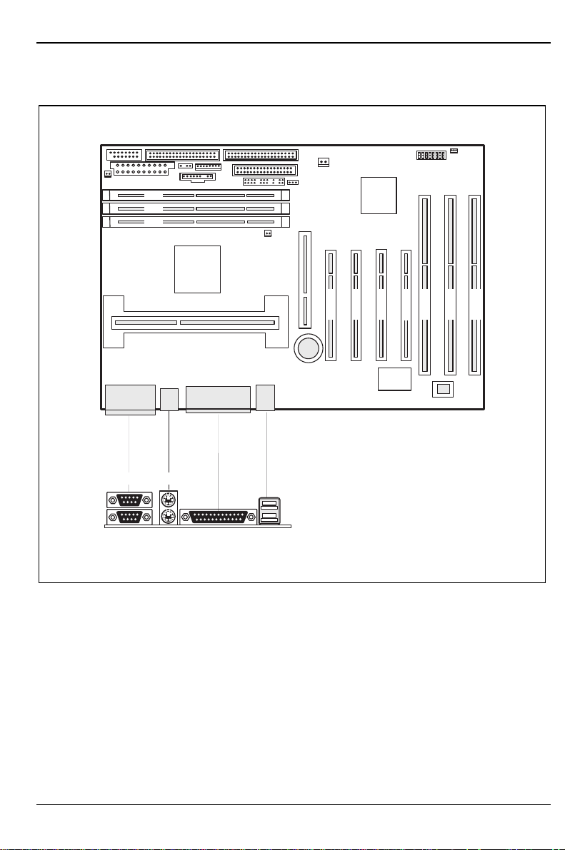
Interfaces and connectors
3 2 1
Features
1
2
1 = Serial port 2
2 = Serial port 1
3 = PS/2 mouse port
3
45 6
PCI 2
PCI 3
PCI 4
4 = PS/2 keyboard port
5 = Parallel port
6 = USB ports
IS A 3
PCI 1
IS A 1
IS A 2
A26361-D1085-Z120-4-7419
English - 5
Features
1
2
3
3 2 1
4
5
6
7
8
9
10
11
12
PCI 4
PCI 3
PCI 2
PCI 1
IS A 3
IS A 2
IS A 1
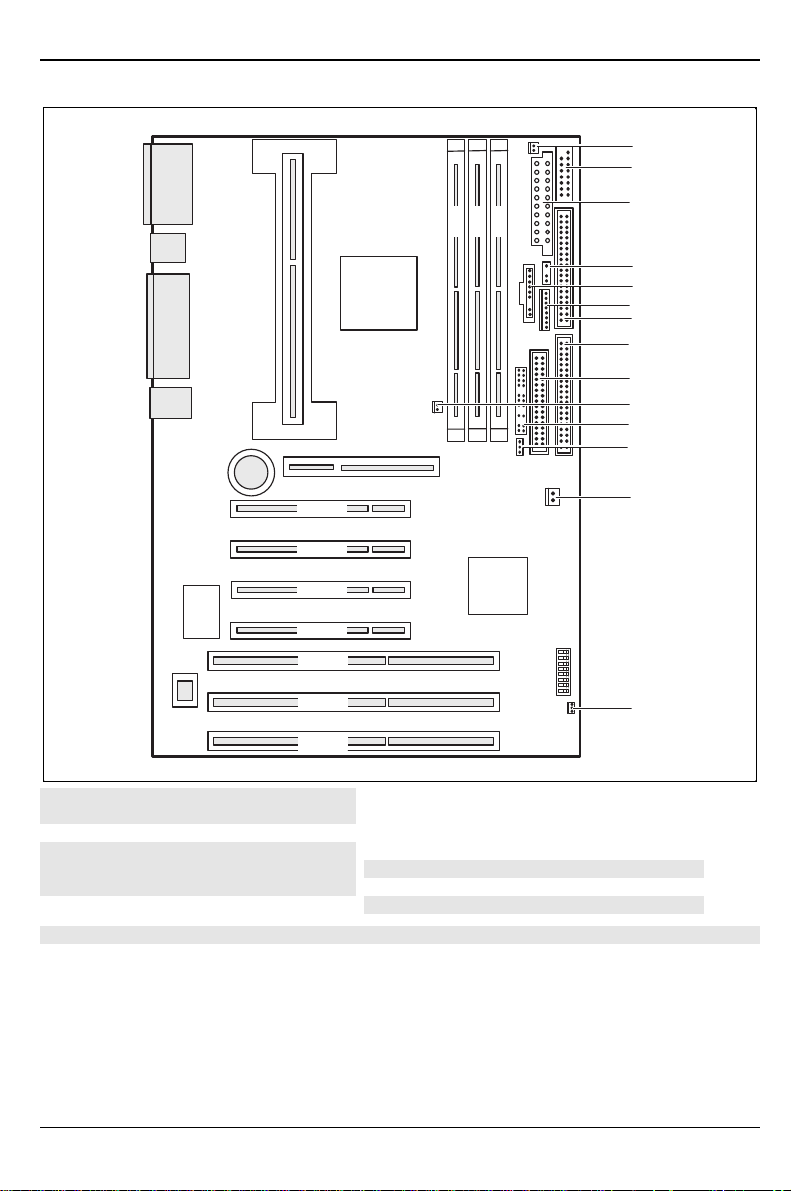
1 = System fan
2 = Chipcard reader
3 = Power supply
4 = Infrared receiver (IrDA)
5 = Device ID
6 = Power supply monitor
7 = IDE drives 3 and 4 (secondary)
The connectors marked do not have to be present on the system board.
8 = IDE drives 1 and 2 (primary)
9 = Floppy disk drive
10 = Processor fan
11 = Control panel
12 = Intrusion plug
13 = Power On
14 = Wake-up on LAN
13
14
6 - English
A26361-D1085-Z120-4-7419
 Loading...