

Page 1
Additional Technical Manual D1042
Introduction
This technical manual applies for the mainboard D1042. This system board is available in different
configuration levels. Depending on the hardware configuration of your device, it may be that you
cannot find several options in your version of the system board, even though they are described.
Further information f. e. the complete
for the BIOS-Setup
are provided on the
technical manual for the D1042
"Drivers & Utility" CD
. For detailed information please look at
and the
reference manual
chapter 3.
1 Features
Version D1042-E
Processor P55C / K6 / MII
AMD-Jumper
Cache 512 KB
Flash 2 MB - PLCC
ATX-SV
Systemmonitoring Graphic Matrox Cyclone
Graphic-Memory 2 MB - SGRAM
Audio Wave-Socket USB 2 x USB
IrDA
Card-Reader
Super-I/O NSC317
KBD-On
Remote-On
SCSI-LED
Frontpanel II I2C-Connector WakeOnLAN -
√
√
√
√
√
√
√
2 Mechanics
CAUTION:
Computer mainboards and components contain very delicate IC chips. To protect them
against damage caused from electric static, you have to follow some precautions:
Unplug your computer when you work inside
•
Hold components by the edge, don't touch their leads
•
Use a grounded wrist strap
•
Place the mainboard and the components on a grounded antistatic pad whenever you work
outside the computer
2.1 Layout
ATX 12'' x 9,6'' (305mm x 244mm)
Some of the following connectors are optional and may therefore not be included on your
mainboard.
A26361-D1042-Z180-2-7619
Seite
1
/ 7
Page 2
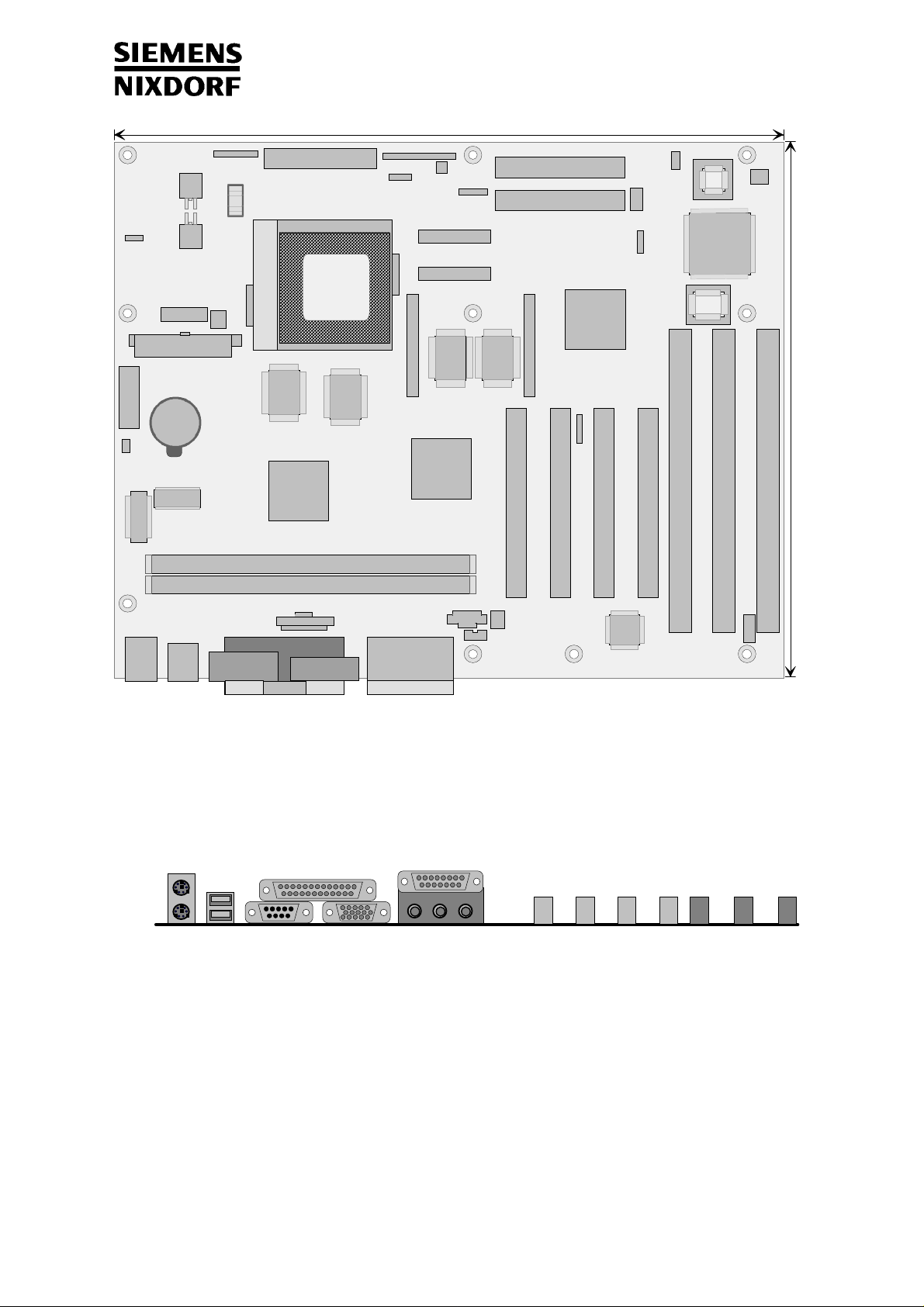
Front Panel 2
Additional Technical Manual D1042
12 '' ( 305 mm )
Floppy
Front Panel 1
SCSI-LED
Power On
Infrared
PCI-IDE 2
PCI-IDE 1
WOL
SM Bus
Faxcard On
Wavetable
VCORE
Voltage Regulator
Power-Supply control
ATX Power-Supply
Cardreader
Case-Switch
CLOCK
DIP-Swit ch
USB B
USB A
Mouse
Keyboard
SOC KET 7
Pentium
Fan
PBSRAM
Battery
MTXC
SDRAM DIMM MODULE Bank 2
SDRAM DIMM MODULE Bank 1
Intrusion
ParallelSerial 1 VGA
PBSRAM
Gameport
VGA Memory Upgrade
Audio
Feature
Feature
SGRAM
MATROX
Mystique
Cyclone
CD-ROM Audio
SGRAM
PCI-SLOT 4
Voice Modem
MPEG Audio
Speaker
PIIX 4
VGA Memory Upgrade
USB
ULTRA I/O
BIOS
9,6 '' ( 244 mm )
ISA-SLOT 3
ISA-SLOT 2
ISA-SLOT 1
PCI-SLOT 3
PCI-SLOT 2
PCI-SLOT 1
DSP upgrade
Audio
Mouse
USB A & B
Keyboard
Parallel
Serial 1 VGA
Gameport
Audio
PCI Slots ISA Slots
Seite 2 / 7
Page 3
Additional Technical Manual D1042
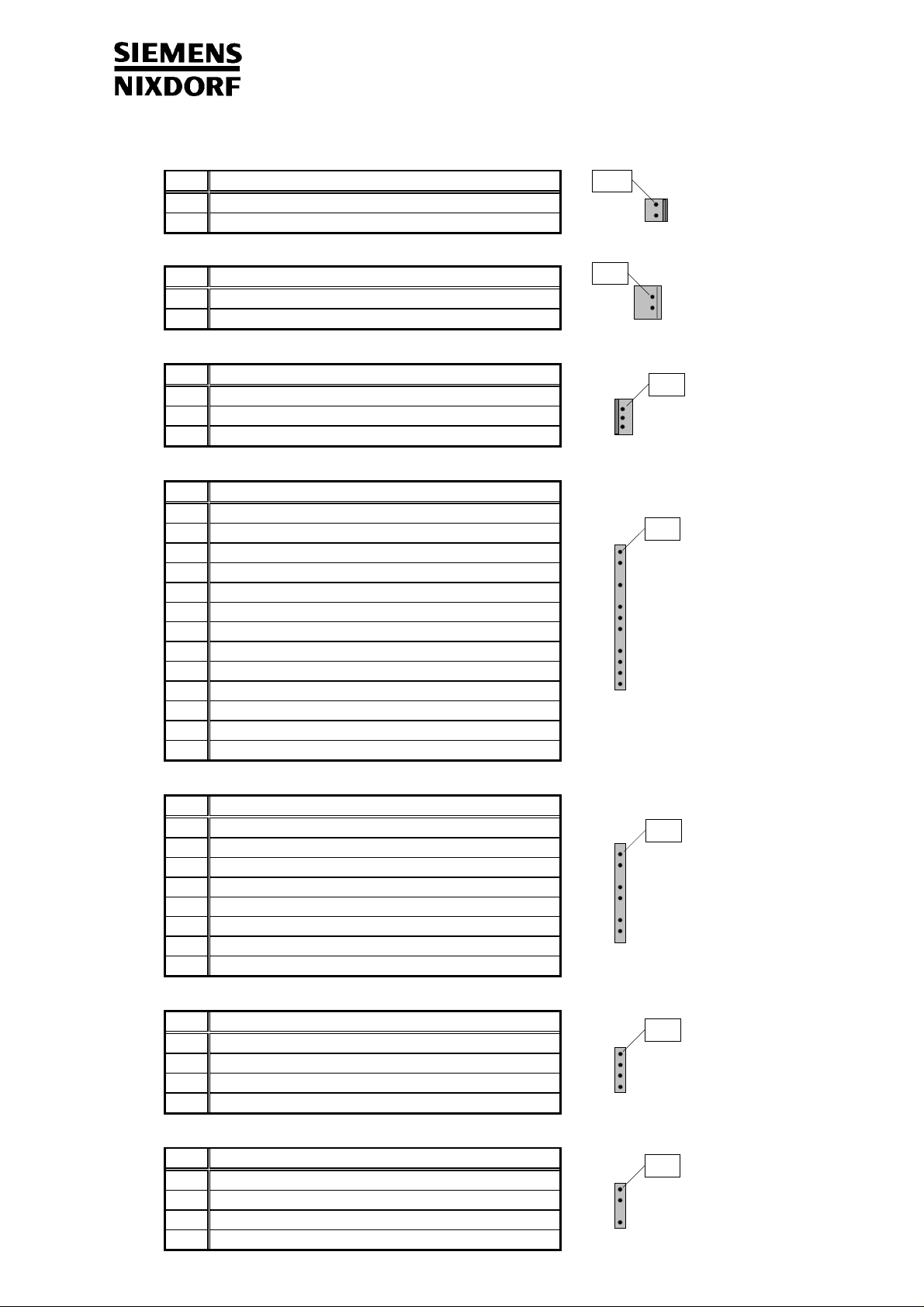
2.2 Connectors, DIP-Switch, Jumpers
2.2.1 Power-On-Switch Connector
Pin
Signal
GND
1
Power-On Pulse (low asserted)
2
2.2.2 Faxcard-On-Connector
Pin
Signal
GND
1
Remote On
2
2.2.3 Wake-On-LAN Connector
Pin
Signal
VCC-Help
1
GND
2
LAN-Wakeup
3
2.2.4 Front Panel Connector 1
Pin
Signal
Boot Lock
1
+ Standby LED
2
3 Key
+ Power LED
4
5 Key
- Standby / Power LED
6
7 n.c.
GND
8
9 Key
+ HD LED
10
HD LED
11
HD LED
12
+ HD LED
13
(some of the following connectors are optional)
Pin 1
Pin 1
Pin 1
Pin 1
2.2.5 Front-Panel Connector 2
Pin
Signal
Reset (low asserted)
1
GND
2
Key
3
n.c.
4
n.c.
5
Key
6
n.c.
7
GND
8
2.2.6 SCSI-LED Connector
Pin
Signal
1 n.c.
HD-LED
2
HD-LED
3
4 n.c.
2.2.7 Speaker Connector
Pin
Signal
VCC
1
GND
2
3 Key
Speaker OUT
4
Pin 1
Pin 1
Pin 1
Seite 3 / 7
Page 4

2.2.8 FAN Connector
Pin
Signal
GND
1
VCC-CPU-Fan
2
CPUA-FanSense
3
2.2.9 ATX-Power-Supply-Connector
Pin
Signal
+ 3.3 V
11
- 12 V
12
GND
13
PS-ON
14
GND
15
GND
16
GND
17
- 5 V
18
+ 5 V
19
+ 5 V
20
2.2.10 Internal Serial Port 2 for Cardreader
Pin
Signal
1 DCD 2 2 DSR 2
3 SIN 2 4 RTS 2
5 SOUT 2 6 CTS 2
7 DTR 2 8 PC-On-Strobe
9 GND 10 VCC-Help
11 EXTSMI 12 VCC
13 RESETDRV 14 GND
15 GND 16 Key
Additional Technical Manual D1042
Pin
1
2
3
4
5
6
7
8
9
10
Pin
Signal
+ 3.3 V
+ 3.3 V
GND
+ 5 V
GND
+ 5 V
GND
Power OK
5 V SB
+ 12 V
Signal
Pin 1
Pin 1Pin 11
Pin 1 Pin 2
2.2.11 Infrared Connector
Pin
Signal
1 VCC
2 Key
3 IRDA-RX
4 GND
5 IRDA-TX
2.2.12 Feature Connector
Pin
Signal
1 GND 2 Video Data 0
3 GND 4 Video Data 1
5 GND 6 Video Data 2
7 Video Enable 8 Video Data 3
9 SYNC Enable 10 Video Data 4
11 DCLK Enable 12 Video Data 5
13 n.c. 14 Video Data 6
15 GND 16 Video Data 7
17 GND 18 DCLK
19 GND 20 BLANK
21 GND 22 HSYNC
23 VIDRST 24 VSYNC
25 Key 26 GND
Pin
Pin 1
Signal
Pin 2Pin 1
Seite 4 / 7
Page 5

y
Additional Technical Manual D1042
2.2.13 Processor Supply-Voltage Setting
Jumper Processor-type 1-2-3
- Intel
1 - 2
AMD K6 - 200 MHz
C
rix M II
Pin 1
2 - 3 AMD K6 - 233 MHz
2.2.14 Configuration SWITCH-Block (DIP-Switch)
for Frequency selection, Recovery and Password clear
Function: SW1 SW2 SW3 SW4 SW5 SW6 SW7 SW8
Recover BIOS
On
Off
Password Skip
On
Off
Floppy Write Protect
On
Off
On = 0 = Close Off = 1 = Open x = don't care
Frequency-setting for Intel P55 (MMX) Processor:
12345678
ON=0
1
ON=0
1
ON=0
1
12345678
1234
166
200
5678
233
xxxxOnxxx
xxxxOffxxx
xxxxxOnxx
xxxxxOffxx
xxxxxxxOn
xxxxxxxOff
BUS = 66 MHz Core = x 2,5
BUS = 66 MHz Core = x 3,0
BUS = 66 MHz Core = x 3,5
Frequency-setting for AMD (K6) Processor:
ON=0
1
12345678
ON=0
1
12345678
ON=0
1
Switch position:
166
200
233
BUS = 66 MHz Core = x 2,5
BUS = 66 MHz Core = x 3,0
BUS = 66 MHz Core = x 3,5
ON (0) OFF (1)
ON=0
slide
or
1
press
5678
1234
2.2.15 PCI-SLOT Configuration And Placement
PCI-SLOT IDSEL Device number
PCI-SLOT 1 ADR 28 11 h
PCI-SLOT 2 ADR 29 12 h
PCI-SLOT 3 ADR 30 13 h
PCI-SLOT 4 ADR 31 14 h
ON=0
slide
or
1
press
Seite 5 / 7
Page 6

Additional Technical Manual D1042
2.3 Power Requirements (Power Supply)
Voltage Max. variation Max. current
+ 5.1 V ± 5 % Tbd
- 5 V ± 5 % Tbd
+ 12 V ± 10 % Tbd
- 12 V ± 10 % Tbd
+ 3.4 V ± 5 % Tbd
+ 5.0 V (aux.) Tbd
Power: minimum 145 W
−
ATX-capable
−
Remote on/off capable
−
Continous voltage of minimum 5V / 20 mA
−
3 Installing drivers and utilities; documentation
Insert the "Drivers & Utilities" CD.
♦
When the DeskStart window appears, select Explore the CD via HTML.
♦
Select the language in which you want to operate the user interface.
♦
Select Scenic Pro and then select f.e. Windows 95.
♦
Here you will find the required drivers, utilities and the additional documentation
For the following components, install the software offered to you in the HTML interface:
♦
Display adapters > Matrox MGA > Install
−
Harddisk-Controller > PIIX4-Support > Install
−
Updates > USB, Siemens Nixdorf USB-Support, DirectX 3.0
−
You will find the description for the Mainboard D1042 under „Documentation“ > Technical Manual
♦
(You may have to install the Acrobat Reader - Software on the CD-ROM (path: utls/acrobat) before
reading!)
For more details please read the according readme.txt files
Seite 6 / 7
Page 7

4 Upgrades
4.1 Main Memory
Further information is given in the main technical manual. For correct functionality of the mainboard
D1042 we recommend the usage of the following DIMM-Modules. For upgrades of the following list,
please ask your local dealer.
16MB DIMM SDRAM, 2Mx64
Producer Part.-No
Samsung KMM366S203BTN-G2
32MB DIMM SDRAM, 4Mx64
Producer Part.-No
NEC MC-454AD644F-A67
SAMSUNG KMM366S403BTN-G2
SIEMENS HYS64V4020GU-10
HYUNDAI HYM7V64400TFG-10
64MB DIMM SD-RAM, 8Mx64
Producer Part.-No
Additional Technical Manual D1042
NEC MC-458CB644F-A10
SAMSUNG KMM366S823AT-G2
128MB DIMM SD-RAM, 16Mx64
Producer Part.-No
NEC MC-4516CD644F-A10
SAMSUNG KMM366S1623AT-G2
4.2 VGA Memory Upgrade
Further information are shown in the main technical manual.
Use only the standard VGA memory extension (up to 8 MB VGA memory) for the Matrox
Mystique 220 grapic cards.
A26361-D1042-Z180-1-7619
Seite 7 / 7
 Loading...