

Page 1
Introduction
This description applies for the System board D1034 with PCI bus (Peripheral
Component Interconnect).
This system board is available in different configuration levels. Depending
i
on the hardware configuration of your device, it may be that you cannot
find several options in your version of the system board, even though
they are described.
You may find further information in the description "BIOS Setup".
Further information to drivers is provided in the readme files on hard disk or on the
supplied drivers diskettes or on the "Drivers & Utility" CD.
Notational conventions
The meanings of the symbols and fonts used in this manual are as follows:
Pay particular attention to texts marked with this symbol. Failure to
!
observe this warning endangers your life, destroys the system, or may
lead to loss of data.
This symbol is followed by supplementary information, remarks and tips.
i
²
Texts which follow this symbol describe activities that must be performed in the
order shown.
³
This symbol means that you must enter a blank space at this point.
ÏÏThis symbol means that you must press the Enter key.
Texts in this typeface are screen outputs from the PC.
Texts in this bold typeface are the entries you make via the keyboard.
Texts in italics indicate commands or menu item.
"Quotation marks" indicate names of chapters and terms that are being
emphasized.
A26361-D1034-Z120-3-7419
English - 1
Page 2

Introduction
Features
ATX system board
•
64-bit microprocessor Intel Pentium with MMX and with 32 Kbytes internal
•
cache (first-Level Cache, 16 Kbytes data cache, 16 Kbytes address cache) or
OverDrive-Processor for Pentium
or
64-bit microprocessor Intel Pentium without MMX and with 16 Kbytes internal
•
cache (first-Level Cache, 8 Kbytes data cache, 8 Kbytes address cache) or
OverDrive-Processor for Pentium
The system board supports Pentium MMX™.
•
256 Kbyte or 512 Kbyte pipelined burst second level cache onboard
•
Memory configuration on the system board: 8 to 256 Mbyte (SDRAM)
•
2 Mbit Flash BIOS
•
3 PCI, 2 ISA slots and 1 ISA/PCI slot (shared) or 3 PCI and 2 ISA slots
•
PCI bus
•
IDE hard disk controller connected to PCI bus for up to four IDE drives
•
(e.g. IDE hard disk drives, ATAPI CD-ROM drives), (prepared for ultra DMA33
mode)
Real-time clock/calendar with integrated battery backup
•
Floppy disk controller (up to 2.88 Mbytes format)
•
Parallel interface (ECP- and EPP-compatible)
•
2 serial ports (16C550 compatible with FIFO)
•
PS/2 mouse port
•
PS/2 keyboard port
•
Security functions
•
Energy saving functions
•
Connector for remote-on (fax/modem board), infrared interface
•
2 - English
A26361-D1034-Z120-3-7419
Page 3

Introduction
A
Optional Components
Prepared for AMD-K5, AMD-K6 or Cyrix M2
•
Audio controller on ISA-BUS (PnP) Crystal CS 4238 or CS 4235 Audio Codec,
•
16 bit stereo; compatible with Soundblaster Pro™, Windows Sound System
and MPU 401; 3D audio support (Q-Sound); internal FM synthesis
The audio output can be set in the BIOS Setup in the screen
i
•
•
•
•
•
•
•
dvanced/Peripheral Configuration
or
Full Power
loudspeaker (with amplifier) to the audio output. Use
passive loudspeakers
Connector for external loudspeaker
Connector for CD-line in, Game/Midi, Voice-Modem, AUX IN
Microphone jack
Audio input (Line in)
Loudspeaker connector (active / passive)
Socket for wavetable chip
Connector for chipcard reader
. Use
Line Level
.
, menu option
if you connect headphones or an active
Audio Output
to
Full Power
Line Level
if you use
USB (Universal Serial Bus)
•
A26361-D1034-Z120-3-7419
English - 3
Page 4
Introduction
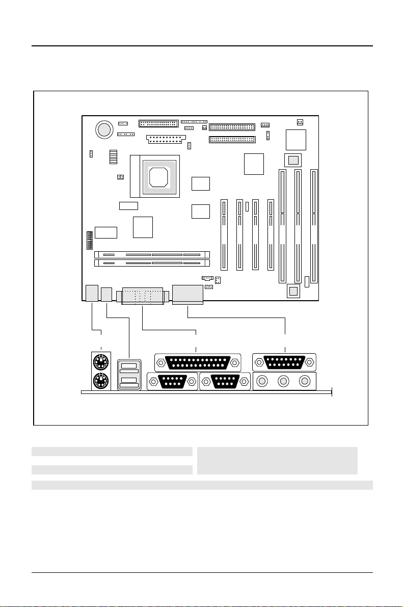
External ports
PCI 1
ISA 3
PCI 2
PCI 3
PCI 4
2 1
1 2
45
1 = PS/2 mouse port
2 = Parallel port
3 = Game/Midi port
4 = PS/2 keyboard port
5 = USB ports
6
7
6 = Serial port 1
7 = Serial port 2
8 = Audio port (Line out)
9 = Audio port (Line in)
10 = Audio port (Microphone)
3
89
The connectors marked do not have to be present on the system board.
ISA 2
10
ISA 1
4 - English
A26361-D1034-Z120-3-7419
Page 5
Introduction
BIOS-Fax
The system board supports the BIOS-Fax function developed by Siemens Nixdorf.
This allows fax reception even if the PC is switched off.
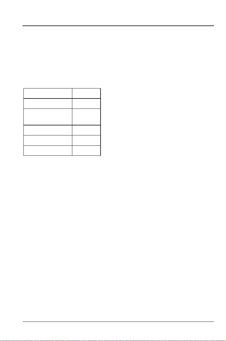
You need a special fax modem kit from Siemens Nixdorf to be able to use this
functionality. This kit is available in the following country variants:
Country Icon
Germany D
Swizzerland
(germany)
Austria A
France F
England GB
Please contact your local distributor or SNI sales office to order the fax modem kit.
CH (D)
Installing drivers
The following drivers are recommended for installation from the "Drivers & Utilities"
CD:
"Crystal" audio board (sound card) (for optional audio functions)
•
Hard disk controller "PIIX4"
•
Software update "DirectX 3.0a"
•
A26361-D1034-Z120-3-7419
English - 5
Page 6
Important notes
Important notes
Keep this manual together with your device. If you pass on the device to third
parties, you should also pass on this manual.
Be sure to read this page carefully and note the information before you
!
open the PC.
Please note the information provided in the chapter "Safety" in the
Operating Manual of the PC.
Incorrect replacement of the lithium battery may lead to a risk of
explosion. It is therefore essential to observe the instructions in the
chapter „Add-on modules
The lithium battery must be replaced with an identical battery or a battery
type recommended by the manufacturer (CR2032).
Do not throw lithium batteries into the trashcan. It must be disposed of in
accordance with local regulations concerning special waste.
This board complies with the requirements of the EEC directive
89/336/EEC with regard to "Electromagnetic compatibility".
Compliance was tested in a typical PC configuration.
“ - „Replacing the lithium battery“.
When installing the board, refer to the specific installation
information in the operating manual or technical manual of the
receiving device.
Connecting cable for peripherals must be adequately insulated to avoid
interference.
Modules can become very hot during operation. Make sure you do not
!
touch modules when adding components to the system board. There is a
danger of burns!
The warranty expires if the device is damaged during the installation or
i
replacement of system expansions. Information on which system
expansions you can use is available from your sales office or the
customer service.
6 - English
A26361-D1034-Z120-3-7419
Page 7

Important notes
Boards with electrostatic sensitive devices (ESD) may be identified by labels.
When you handle boards fitted with ESDs, you must observe the following points
under all circumstances:
You must always discharge yourself (e.g. by touching a grounded object)
•
before working.
The equipment and tools you use must be free of static charges.
•
Pull out the power plug before inserting or pulling out boards containing
•
ESDs.
Always hold boards with ESDs by their edges.
•
Never touch pins or conductors on boards fitted with ESDs.
•
A26361-D1034-Z120-3-7419
English - 7
Page 8
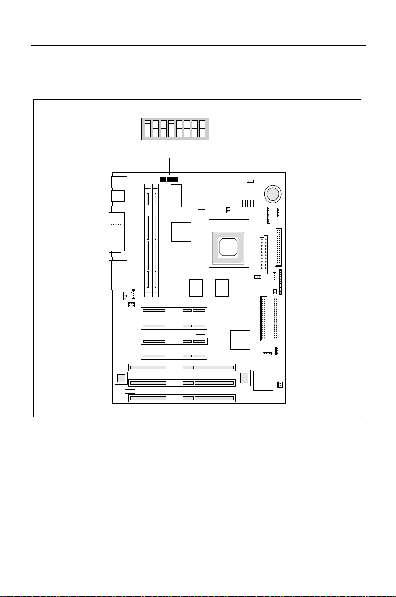
Settings with switch block
Settings with switch block
2
1
4
678
3
ON
2 1
5
OFF/OPEN
PCI 4
PCI 3
PCI 2
PCI 1
ISA 3
ISA 2
ISA 1
Switch 1, 2, 3 and 4 = clock speed
Switch 5 = recovering system BIOS
Switch 6 = must be set to
off
8 - English
Switch 7 = reserved
Switch 8 = write protection for floppy disk
drive
A26361-D1034-Z120-3-7419
Page 9
Settings with switch block
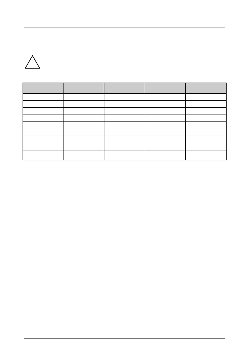
Clock speed - switch 1, 2, 3 and 4
The switches may only be set as specified in the table below for the
!
particular processor used. Make sure you also check the jumper settings
for the processor auxiliary voltage.
Processor switch 1 switch 2 switch 3 switch 4
90 MHz off on off off
100 MHz on off off off
120 MHz off on on off
133 MHz on off on off
150 MHz off on on on
166 MHz on off on on
200 MHz on off off on
233 MHz on off off off
Reserved off off off off
Recovering System BIOS - switch 5
Switch 5 enables recovery of the old system BIOS after an attempt to update has
failed. Memory bank 1 must be populated in order to be able to restore the system
BIOS. To restore the old BIOS you need a Flash BIOS Diskette (call customer
service).
on The System BIOS executes from floppy drive A: and restores the
System BIOS on the system board.
off The System BIOS is started from the system board (default
setting).
Skipping the password setting - switch 6
Switch 6 defines whether a set BIOS password is to be taken into account or not.
on The BIOS password is ignored.
off The BIOS password is taken into account (default setting).
A26361-D1034-Z120-3-7419
English - 9
Page 10

Settings with switch block
Write-protection for floppy disk drive - switch 8
Switch 8 is used to define whether floppy disks can be written or deleted in the
floppy disk drive. To write and delete floppy disks, the write-protection in BIOS
setup must be disabled (in menu Security, the field Diskette Write must be set to
Enabled).
on The floppy disk drive is write-protected.
off Read, write and delete floppy disks is possible (default setting).
10 - English
A26361-D1034-Z120-3-7419
Page 11

Add-on modules
Add-on modules
15
2 1
12
10
9
8
1 = Locations 1 + 2 for main memory
2 = Switch block
3 = Processor with heat sink
4 = Jumper for the supply voltage of an
AMD-K5 processor
5 = Jumper for processor core voltage
The connectors marked do not have to be present on the system board.
PCI 4
PCI 3
PCI 2
PCI 1
ISA 3
ISA 2
ISA 1
31142
6 = Lithium battery
7 = Flash BIOS
8 = ISA slots 1 - 2
9 = Socket for wavetable chip
10 = ISA slot 3
11 = PCI slots 1 - 3
12 = PCI slot 4
Modules can become very hot during operation. Make sure you do not
!
touch modules when adding components to the system board. There is a
danger of burns!
6
7
A26361-D1034-Z120-3-7419
English - 11
Page 12

Add-on modules
Upgrading main memory
Two locations (bank 1 and bank 2) are available on the system board for installing
memory modules. DIMM modules (dual inline memory module) are used.
A maximum of 256 Mbytes of SDRAM memory modules may be installed.
You may only use unbuffered 3.3V modules. Buffered modules are not
!
permitted.
You can only use 66 MHz or faster SDRAM memory modules!
Installing memory modules
²
Flip the retainers to the left and right of the location outward.
²
Insert the memory module into the appropriate location.
²
Press the lateral holders until they snap in place.
²
Press the lateral holders firmly against the location.
Removing a memory module
²
Flip the holders to the right and left of the location outwards.
²
Pull the memory module out of its location.
12 - English
A26361-D1034-Z120-3-7419
Page 13

Recommended memory modules
16MB DIMM SDRAM 2Mx64
Producer Part.-No
SAMSUNG KMM366S203BTN-G2
32MB DIMM SDRAM 4Mx64
Producer Part.-No
NEC MC-454AD644F-A67
SAMSUNG KMM366S403BTN-G2
SIEMENS HYS64V4020GU-10
HYUNDAI HYM7V64400TFG-10
64MB DIMM SDRAM 8Mx64
Producer Part.-No
NEC MC-458CB644F-A10
SAMSUNG KMM366S823AT-G2
Add-on modules
128MB DIMM SDRAM 16Mx64
Producer Part.-No
NEC MC-4516CD644F-A10
SAMSUNG KMM366S1623AT-G2
A26361-D1034-Z120-3-7419
English - 13
Page 14

Add-on modules
Replacing the processor
2
3
1
²
Push the lever in the direction of the arrow (1) and lift it as far as it will go (2).
²
Remove the old processor from the socket (3).
²
Insert the new processor in the socket so that the mark on the upper side of
the processor matches the mark (A) on the socket (4).
The mark on the processor may be covered by a heat sink. In this case
!
let yourself be guided by the marking in the rows of pins on the underside
of the processor.
4
5
A
²
Push the lever back down so that it snaps into place.
²
Set the switches 1, 2 , 3 and 4 depending on the processor which is installed.
14 - English
A26361-D1034-Z120-3-7419
Page 15

Setting the processor core voltage
The jumpers may only be set as specified in the table below for the
!
particular processor used!
Add-on modules
Processor type Jumper for processor core
voltage
Intel not inserted not inserted
AMD-K5 not inserted both inserted
AMD-K6 - 166
AMD-K6 - 200
AMD-K6 - 233 connected to 2-3 not inserted
connected to 1-2 both inserted
Jumper for the supply
voltage of an AMD-K5
Upgrading the wavetable module
If the system board is prepared for upgrading with a single-chip wavetable module
(Crystal CS9236), the upgrade is carried out as shown in the figure.
A26361-D1034-Z120-3-7419
English - 15
Page 16

Add-on modules
Replacing the lithium battery
Incorrect replacement of the lithium battery may lead to a risk of
!
explosion.
The lithium battery must be replaced with an identical battery or a battery
type recommended by the manufacturer (CR2032).
Do not throw lithium batteries into the trashcan. It must be disposed of in
accordance with local regulations concerning special waste.
Make sure that you insert the battery the right way round. The plus pole
must be on the top!
1
+
+
²
Lift the contact (1) a few millimeters and remove the battery from its
socket (2).
²
Insert a new lithium battery of the same type in the socket (3).
2
+
3
+
16 - English
A26361-D1034-Z120-3-7419
Page 17

Connectors and resources
Overview of connections
2 1
16
15
14
1 = Infrared interface
2 = RESET switch
3 = Floppy disk drive
4 = Power supply
5 = SCSI LED
6 = LED indicators in front panel
7 = Power on switch
PCI 4
PCI 3
PCI 2
PCI 1
ISA 3
ISA 2
ISA 1
10 = IDE drives 3 and 4 (secondary)
11 = I2C connector
12 = External loudspeaker
13 = Remote on via fax/modem
14 = Voice modem
15 = AUX Line in
16 = CD Line in
8 = Fan
9 = IDE drives 1 and 2 (primary)
The connectors marked do not have to be present on the system board.
1
9
10
11
12
13
2
3
4
5
6
7
8
A26361-D1034-Z120-3-7419
English - 17
Page 18

Connectors and resources
Resource table
assigned
IRQ
Keyboard IRQ1
IrDA / COM2 IRQ3 02F8, 03F8
Serial interface COM1 IRQ4 03F8, 02F8
Floppy disk drive controller IRQ6 DMA2
Parallel interface LPT1 IRQ7 IRQ5, IRQ7 0278, 0378 DMA1, DMA3
RTC IRQ8
Audio controller
Joystick:
Base address:
MPU 401:
Adlib:
USB controller IRQ11
Mouse controller IRQ12
Numeric processor IRQ13
IDE controller 1 IRQ14
IDE controller 2 IRQ15
"assigned IRQ" = interrupts assigned as shipped
"Possible IRQ" = these interrupts can be used for your particular application
"Possible address= this address can be used for your particular application
"Possible DMA" = these DMAs can be used for your particular application
possible IRQ Possible
Address
02E8, 03E8
03E8, 02E8
IRQ5, IRQ7,
IRQ9, IRQ11;
IRQ12; IRQ15
0200-0207
0220-022F
0240-024F
0260-026F
0280-028F
0300-0301
0330-0331
0338-038B
Possible
DMA
DMA1, DMA3,
DMA0
MPU 401: If you want to use external MIDI devices (for example a MIDI
i
keyboard), you must assign an interrupt for the MPU 401 (MIDI interface).
Detailed information is provided in the audio documentation on the driver
and utility CD.
Please note that a resource cannot be used by two applications at the
same time.
18 - English
A26361-D1034-Z120-3-7419
Page 19

Connectors and resources
Power supply
For a PC equipped as standard we recommend a 145W power supply with 3.3 V
and 5 V auxiliary voltages, e g.:
Voltage Max. deviation Max. current
+ 5 V +/- 5 % 18 A
- 5 V +/- 10 % 0,3 A
+ 12 V +/- 10 % 4,2 A
- 12 V +/- 10 % 0,4 A
+ 3.4 V +/- 5 % 10 A
+ 5.0 V (aux) 20 A
PCI slot configuration and setting
PCI-SLOT IDSEL Device number
PCI-SLOT 1 ADR 28 11h
PCI-SLOT 2 ADR 29 12h
PCI-SLOT 3 ADR 30 13h
PCI-SLOT 4 ADR 31 14h
A26361-D1034-Z120-3-7419
English - 19
Page 20

Pin-Assignment
Power ON Switch-Connector
Pin Signal
1 GND
2 Power-On Pulse (low asserted)
Faxcard-On-Connector
Pin
1 GND
2 Remote On
Front Panel Connector 1
Pin
1 Boot Lock
2 + Standby LED
3 Key
4 + Power LED
5 Key
6 - Standby / Power LED
7 n.c.
8 GND
9 Key
10 + HD LED
11 HD LED
12 HD LED
13 + HD LED
Signal
Signal
Pin 1
Pin 1
Pin 1
A26361-D1034-Z120-3-7419 PIN-Assignment
1
-
Page 21

Front Panel Connector 2
Pin-Assignment
Pin
Signal
1 Powergood / Reset
2 GND
3 Key
4 n.c.
5 n.c.
6 Key
7 n.c.
8 GND
SCSI-LED Connector
Pin
Signal
1 n.c.
2 HD-LED
3 HD-LED
4 n.c.
Speaker Connector
Pin
Signal
1 VCC
2 GND
3 Key
4 SPEAKER OUT
Pin 1
Pin 1
Pin 1
FAN Connector (symmetrical)
Pin
Signal
Pin 1
1 GND
2 + 12 V
3 GND
A26361-D1034-Z120-3-7419 PIN-Assignment
2
-
Page 22

ATX-Power-Supply-Connector
Pin-Assignment
Pin
Signal
Pin
Signal
11 3.3 V 1 3.3 V
12 - 12 V 2 3.3 V
13 GND 3 GND
14 PS-ON 4 5 V
15 GND 5 GND
16 GND 6 5 V
17 GND 7 GND
18 - 5 V 8 Power OK
19 5 V 9 5 V SB
20 5 V 10 12 V
Floppy Connector
Pin
Signal
Pin
Signal
1 GND 2 FDHDIN
3 GND 4 n.c.
5 Key 6 n.c.
7 GND 8 Index
9 GND 10 Motor Enable A
11 GND 12 Drive Select B
13 GND 14 Drive Select A
15 GND 16 Motor Enable B
17 GND 18 Step DIR
19 GND 20 Step Pulse
21 GND 22 Write Data
23 GND 24 Write Enable
25 GND 26 Track 0
27 GND 28 Write Protect
29 GND 30 Read Data
Pin 1Pin 11
Pin 2Pin 1
31 GND 32 Side 1 Select
33 GND 34 Disk Change
A26361-D1034-Z120-3-7419 PIN-Assignment
3
-
Page 23

PCI-IDE Connector
Pin-Assignment
Pin
Signal
Pin
Signal
1 Reset Drive 2 GND
3 Data 7 4 Data 8
5 Data 6 6 Data 9
7 Data 5 8 Data 10
9 Data 4 10 Data 11
11 Data 3 12 Data 12
13 Data 2 14 Data 13
15 Data 1 16 Data 14
17 Data 0 18 Data 15
19 GND 20 Key
21 DRQ 22 GND
23 I/O Write 24 GND
25 I/O Read 26 GND
27 IORDY 28 Cable Select
29 DACK 30 GND
31 IRQ 32 n.c.
33 ADR 1 34 n.c.
35 ADR 0 36 ADR 2
37 Chip Select 1 38 Chip Select 3
39 IDE-LED 40 GND
Serial Port 1 (V24) / Serial Port 2
Pin
Signal
Pin
Signal
Pin 1
Pin 1
Pin 2
1 DCD 1 6 DSR 1
2 SIN 1 7 RTS 1
3 SOUT 1 8 CTS 1
4 DTR 1 9 RI 1 (Remote On)
Pin 6
5 GND
A26361-D1034-Z120-3-7419 PIN-Assignment
4
-
Page 24

Parallel Port
Pin-Assignment
Pin 1
Pin 14
Pin
Signal
Pin
Signal
1 STROBE 14 AUTOFD
2 LPT DAT 0 15 ERROR
3 LPT DAT 1 16 INIT
4 LPT DAT 2 17 LPT SEL
5 LPT DAT 3 18 GND
6 LPT DAT 4 19 GND
7 LPT DAT 5 20 GND
8 LPT DAT 6 21 GND
9 LPT DAT 7 22 GND
10 ACK 23 GND
11 BUSY 24 GND
12 PEMTY 25 GND
13 SELECT
Keyboard Port Connector
Pin
Signal
1 KBD DAT
2 n.c. (optional MOUSE DAT)
3 GND
4 VCC
5 KBD CLK
6 Key ON/OFF (optional MOUS E CLK)
Pin 2 Pin 1
A26361-D1034-Z120-3-7419 PIN-Assignment
5
-
Page 25

Mouse Port Connector
Pin-Assignment
Pin
Signal
1 MOUSE DAT
2 n.c.
3 GND
4 VCC
5 MOUSE CLK
6 n.c.
USB Connector A / B
Pin
Signal
1 VCC
2 DATA_NEGATIVE
3 DATA_POSITIVE
4 GND
Pin 1Pin 2
PIN 1 B
PIN 1 A
A26361-D1034-Z120-3-7419 PIN-Assignment
6
-
Page 26

Audio/Gameport-Connector
Pin-Assignment
Pin 1
Pin 9
Speaker /
Line Output
Pin
Line Input Microphone
Signal
Input
Pin
Signal
1 GAME_VCC 9 GAME_VCC
2 JOY_PORT_L<0> 10 JOY_PORT_L<2>
3 XJOY_TIMER_A<0> 11 XJOY_TIMER_A<2>
4 GND 12 XMIDI_OUT_H
5 GND 13 XJOY_TIMER_A<3>
6 XJOY_TIMER_A<1> 14 JOY_PORT_L<2>
7 JOY_PORT_L<1> 15 XMIDI_EXT_IN_H
8 GAME_VCC
Internal CD-ROM Audio Connector
Pin
Signal
Pin 1
1 Left CD Audio Input
2 GND
3 GND
4 Right CD Audio Input
A26361-D1034-Z120-3-7419 PIN-Assignment
7
-
Page 27

Internal MPEG Audio Connector
Pin-Assignment
Pin
Signal
Pin 1
1 GND
2 Left MPEG Audio Input
3 GND
4 Right MPEG Audio Input
Internal Voice Modem Connector
Pin
Signal
Pin
Signal
1 Speaker Input from MODEM 2 n.c.
3 GND 4 Key
5 Microphone Output to
6 n.c.
MODEM
Infrared Connector
Pin
Signal
Pin 1
1 VCC
2 Key
3 IRDA_RX
4 GND
5 IRDA_TX
Pin 2Pin 1
A26361-D1034-Z120-3-7419 PIN-Assignment
8
-
Page 28

Contents
Pin-Assignment......................................................................................................1
Power ON Switch-Connector............................................................................1
Faxcard-On-Connector.....................................................................................1
Front Panel Connector 1...................................................................................1
Front Panel Connector 2...................................................................................2
SCSI-LED Connector........................................................................................2
Speaker Connector...........................................................................................2
FAN Connector (symmetrical)...........................................................................2
ATX-Power-Supply-Connector..........................................................................3
Floppy Connector..............................................................................................3
PCI-IDE Connector...........................................................................................4
Serial Port 1 (V24) / Serial Port 2......................................................................4
Parallel Port ......................................................................................................5
Keyboard Port Connector .................................................................................5
Mouse Port Connector......................................................................................6
USB Connector A / B........................................................................................6
Audio/Gameport-Connector..............................................................................7
Internal CD-ROM Audio Connector...................................................................7
Internal MPEG Audio Connector.......................................................................8
Internal Voice Modem Connector .....................................................................8
Infrared Connector............................................................................................8
A26361-D1034-Z120-3-7419 English
Page 29

A26361-D1034-Z120-3-7419
Systembaugruppe D1034
System board D1034 - PIN-Assignment
January 1998 edition
Creative is a registered trademark, Sound Blaster 16 and VIBRA 16C are trademarks of
Technology Ltd.
Intel and Pentium are registered trademarks and OverDrive is a trademark of Intel
Corporation, USA.
AMD-K5, AMD-K6 are trademarks of Advanced Micro Devices, Inc..
Microsoft, MS, MS-DOS and Windows are registered trademarks of Microsoft Corporation.
PS/2 and OS/2 Warp are registered trademarks of International Business Machines, Inc.
All other trademarks referenced are trademarks or registered trademarks of their respective
owners, whose protected rights are acknowledged.
Copyright Siemens Nixdorf Informationssysteme AG 1998.
All rights, including rights of translation, reproduction by printing, copying or similar methods,
even of parts are reserved.
Offenders will be liable for damages.
All rights, including rights created by patent grant or registration of a utility model or design,
are reserved.
Delivery subject to availability. Right of technical modification reserved.
A26361-D1034-Z120-3-7419
Page 30

Contents
Introduction............................................................................................................1
Notational conventions............................................................................................ 1
Features..................................................................................................................2
External ports ..........................................................................................................4
BIOS-Fax................................................................................................................. 4
Installing drivers ......................................................................................................5
Important notes .....................................................................................................6
Settings with switch block.................................................................................... 8
Clock speed - switch 1, 2, 3 and 4 .......................................................................... 9
Recovering System BIOS - switch 5........................................................................ 9
Skipping the password setting - switch 6 ................................................................9
Write-protection for floppy disk drive - switch 8..................................................... 10
Add-on modules.................................................................................................. 11
Upgrading main memory.......................................................................................12
Recommended memory modules...................................................................13
Replacing the processor........................................................................................ 14
Setting the processor core voltage................................................................. 15
Upgrading the wavetable module.......................................................................... 15
Replacing the lithium battery.................................................................................16
Connectors and resources................................................................................. 17
Overview of connections.......................................................................................17
Resource table......................................................................................................18
Power supply.........................................................................................................19
PCI slot configuration and setting.......................................................................... 19
A26361-D1034-Z120-3-7419 English
Page 31

A26361-D1034-Z120-3-7419
System board D1034
Technical Manual
January 1998 edition
Creative is a registered trademark, Sound Blaster 16 and VIBRA 16C are trademarks of
Technology Ltd.
Intel and Pentium are registered trademarks and OverDrive is a trademark of Intel
Corporation, USA.
AMD-K5, AMD-K6 are trademarks of Advanced Micro Devices, Inc..
Microsoft, MS, MS-DOS and Windows are registered trademarks of Microsoft Corporation.
PS/2 and OS/2 Warp are registered trademarks of International Business Machines, Inc.
All other trademarks referenced are trademarks or registered trademarks of their respective
owners, whose protected rights are acknowledged.
Copyright Siemens Nixdorf Informationssysteme AG 1998.
All rights, including rights of translation, reproduction by printing, copying or similar methods,
even of parts are reserved.
Offenders will be liable for damages.
All rights, including rights created by patent grant or registration of a utility model or design,
are reserved.
Delivery subject to availability. Right of technical modification reserved.
A26361-D1034-Z120-3-7419
 Loading...